EP2042018A1 - Windrow forming construction - Google Patents
Windrow forming construction Download PDFInfo
- Publication number
- EP2042018A1 EP2042018A1 EP08165101A EP08165101A EP2042018A1 EP 2042018 A1 EP2042018 A1 EP 2042018A1 EP 08165101 A EP08165101 A EP 08165101A EP 08165101 A EP08165101 A EP 08165101A EP 2042018 A1 EP2042018 A1 EP 2042018A1
- Authority
- EP
- European Patent Office
- Prior art keywords
- main body
- harvesting machine
- spreader assembly
- generally
- spreader
- Prior art date
- Legal status (The legal status is an assumption and is not a legal conclusion. Google has not performed a legal analysis and makes no representation as to the accuracy of the status listed.)
- Granted
Links
Images




Classifications
-
- A—HUMAN NECESSITIES
- A01—AGRICULTURE; FORESTRY; ANIMAL HUSBANDRY; HUNTING; TRAPPING; FISHING
- A01D—HARVESTING; MOWING
- A01D41/00—Combines, i.e. harvesters or mowers combined with threshing devices
- A01D41/12—Details of combines
- A01D41/1243—Devices for laying-out or distributing the straw
Definitions
- the present invention relates generally to a harvesting machine, for example an agricultural combine, with a construction for controlling and channeling the discharge of crop residue, and more particularly to the provision of a windrow forming construction for use in forming windrows of crop residue behind the harvesting machine as a crop is harvested.
- Axially arranged rotary threshing or separating systems have long been in use in agricultural combines for threshing crops to separate grain from crop residue, also referred to as material other than grain (MOG).
- Such axially arranged systems typically include at least one cylindrical rotor rotated within a concave or cage, the rotor and surrounding concave being oriented so as to extend forwardly to rearwardly within the combine.
- crop material is fed or directed into a circumferential passage between the rotor and the concave, hereinafter referred to as a rotor residue passage, and is carried rearwardly along a generally helical path in such passage by the rotation of the rotor as grain is threshed from the crop material.
- the flow of crop residue or MOG remaining between the rotor and concave after threshing is typically discharged or expelled by the rotating rotor at a rear or downstream end of the rotor and the rotor residue passage in a generally downward, or a downward and sidewardly, direction in what is a continuation of the helical path of movement of the crop residue within the rotor residue passage between the rotor and concave.
- the flow is typically discharged into a discharge opening at the downstream end of the rotor and into a further passage, hereinafter referred to as a discharge passage, that extends downwardly and somewhat rearwardly into a crop residue distribution system located below and rearwardly of the rear end of the threshing system.
- the crop residue distribution system typically includes a rotary beater or chopper or other apparatus that beats or chops the residue into smaller pieces and propels that finer crop residue rearwardly towards an area within the rear end of a combine, hereinafter referred to as a distribution chamber.
- the crop residue provided to the distribution chamber may be discharged therefrom onto a field either as a windrow or by spreading the crop residue across a crop swath cut.
- the crop residue may simply be discharged from an exit port over the top of a spreader assembly at the rear of the combine to bypass the spreader assembly and to fall upon the ground behind the spreader assembly when windrowing is desired.
- the crop residue is discharged from a rear residue output port towards a spreader assembly, or at least the position in which a spreader assembly would be located, for windrowing or swath spreading, depending upon the setup of the spreader assembly employed.
- Typical spreader assemblies employed include pairs of counter rotating spreader head assemblies mounted side by side to each other generally below and to the rear of a rear crop residue output port, sometimes with rubber or like curtains or shields installed extending at least part way along the sides from the front of the spreader assembly.
- Such spreader head assemblies include spreader plates, the rotation of which helps propel and direct crop residue falling onto the spreader plates for distribution.
- spreader plates are typically generally flat disks which often are configured to have spaced spreader bats on one side, generally considered the topside of the spreader plate. The bottom sides of such spreader plates typically are relatively flat.
- such spreader plates are generally mounted with the topside including the spreader bats facing upwardly so that the spreader bats can assist in throwing the crop residue somewhat sidewardly.
- the spreader plates are generally mounted with the topside including the spreader bats facing downwardly and with the relatively flat bottom sides facing upwardly. In such configuration, the crop residue falls onto the relatively flat upwardly facing bottom sides of the spreader plates and is propelled rearwardly by the counter-rotation of such spreader plates.
- a user may even elect to totally remove or forego use of the spreader plates of a spreader assembly, or even to forego the use of a spreader assembly, and to simply discharge the crop residue from the rear residue output port directly onto the field.
- a harvesting machine comprising:
- the rotatable side deflectors permit the user to adjust or controllably vary to some extent the lateral width of a windrow and the degree to which the crop residue is spread over the swath, as will be further explained below.
- the side deflectors comprise first portions associated with the connected ends thereof and second portions associated with said free ends thereof, the first and second portions being engaged with one another to be slidable relative to one another to vary the length of the side deflectors between a minimum retracted length and a maximum extended length.
- the side deflectors and the main body comprise mechanisms having portions complementarily engagable with one another to latch the side deflectors in place at the desired rotational positionings about their respective deflector rotation axes.
- the main body comprises an outer base frame having a front portion connectable to the harvesting machine, a rear portion extending to beyond the rear of the spreader assembly footprint area, and side portions extending beyond the sides of the spreader assembly footprint area and an upper deck disposed within the outer base frame extending to cover the substantial entirety of the spreader assembly footprint area.
- the outer base frame is preferably of a generally rectangular racetrack or ovaloid configuration.
- the upper deck is preferably of a generally trapezoidal shape, having a wider portion generally adjacent the front portion of said outer base frame, a narrower portion generally along the rear portion of the outer base frame, and side portions extending between the wider and narrower portions, said side portions comprising angled areas having edge deflectors thereat for deflecting crop residue downwardly.
- the main body is mountable to the rear of the harvesting machine for rotational movement about a generally horizontal axis of rotation generally laterally transverse to the harvesting machine defining a main body rotation axis, and in that a positioning mechanism is operatively connectable to the harvesting machine and to the main body to support said main body at a plurality of rotational positions about said main body rotation axis.
- This positioning mechanism is operable to vary the inclination of the main body portion relative to the ground surface, the effect of which may be to vary the degree with which the crop residue is directed into the stubble remaining on the field, and to support and maintain the main body portion in desired positions.
- the side deflectors are disposed at or near opposite sides of the construction to be adjustably movable to controllably vary to some extent the sidewardly distribution of the crop residue and the width of the resulting windrow.
- the positioning mechanism of comprises a pair of lift arms connected to the outer base frame and a pair of support arms that are engaged with the lift arms to provide support therefor.
- the lift arms have front portions connected to the front portion of the outer base frame and rear portions connected to the rear portions of the outer base frame.
- the support arms have front ends connectable to the rear of the combine at elevations higher than the frame mounting elevation and rear ends connectable to the rear portions of respective lift arms.
- the front ends of the support arms may be connected to fixed positions on the combine or associated equipment and the rear ends of such support arms may be configured to engagably ride within slots that extend along the rear portions of the lift arms or to rest within associated spaced lock niches along the upper sides of the slots, which elements permit elevational adjustments and repositionings of the rear portion of the outer base frame.
- the rear ends of the support arms are moved rearwardly along the slots, the elevation of the rear portion of the outer base frame increases, and as the rear ends of the support arms are moved forwardly along the slots, the elevation of the rear portion of the outer base frame decreases, with such actions effecting variations in the inclination of the main body relative to the ground surface.
- the weight of the main body and the deflectors serves to lock the rear portion of the outer frame base at a given elevation and the main body at a given inclination.
- the slots and lock niches are disposed along the rear ends of the lift arms such that, when the rear ends of the support arms are engaged with and in the most rearward lock niches, the outer frame base extends and is supported generally horizontal to the ground, and when the rear ends of the support arms are engaged with and in the most forward lock niches, the outer frame base extends almost fully downward, in a service position.
- the rear ends of the support arms may be connected to the lift arms at fixed points instead of riding along slots in the lift arms, and the front ends of such support arms may be adjustably variably engaged with slot and lock systems on the combine or associated equipment, which slot and lock systems may be similar in many respects to the slots and lock niches that have been discussed hereinabove, and/or the support arms may include telescopic or piston like portions which could be adjustably varied by a user to alter the inclination of the main body relative to the ground surface.
- the positioning mechanism could also include other types of lift assemblies connectable between the rear portion of the outer frame base and the combine or associated equipment, which lift assemblies may be operable to vary the height or elevation of the rear of such outer frame base, including by the use of hydraulic cylinders or electric motors or other acceptable mechanisms which can be operated to similar effect, which devices and mechanisms may further be remotely actuatable and controllable by the user from the cab of the combine.
- a method for discharging crop residue from a harvesting machine according to the first aspect of the invention characterised in that the rotational positioning of the side deflectors about their respective deflector rotation axes to a desired position establishes a desired windrow width or swath spreading width of the crop residue.
- the rotational positioning of the main body about the main body rotation axis to a desired position establishes a desired inclination at which the crop residue towards is directed to the ground surface.
- the windrow forming construction can be configured to permit the relatively unencumbered operation of the spreader assembly. This can be accomplished, at least in part, by setting or retracting the side deflectors to their retracted minimum lengths, by rotating the deflectors outwardly from one another about their respective deflector rotation axes to open the spacing between the free seconds ends of deflectors, and by maintaining the main body at or near a generally horizontal inclination relative to the ground surface.
- the spreader assembly can then operate in its standard manner to effect swath spreading of the crop residue.
- the windrow forming construction can be re-configured to generally establish a desired windrow width and the degree to which a user desires the crop residue to be directed into the stubble remaining on the field. This can be accomplished, at least in part, by extending the side deflectors to desired lengths to limit, to some extent, the sidewardly distribution of the crop residue, by rotating the deflectors inwardly towards one another about their respective deflector rotation axes to narrow the spacing between the free seconds ends of deflectors to a desired distance or width, and by rotating the main body about the main body rotation axis to a desired inclination relative to the ground surface.
- the spreader assembly can then operate in its windrow mode, with the spreader plates mounted with their associated spreader bats facing downwardly and with the flat sides of the spreader plates facing upwardly, to propel the crop residue rearwardly to be channeled and formed into a windrow by the windrow forming construction.
- the present invention thus provides a new and improved construction and technique for better forming windrows behind a combine, including windrows that may be deposited on the filed as relatively uniform cohesive mats the elevations of which may be better or somewhat adjustably controllable relative to the remaining stubble on the field, which construction and technique overcome or obviate or lessen various of the previous difficulties and concerns encountered with the formation of windrows.
- Figure 1 depicts the rear portion of a typical combine 20 having a pair of rear tires 22 mounted upon a rear axle 24, with a grain auger or threshing rotor 26, an engine radiator air screen 28, and handrails 29 mounted upon the upper structure of the combine 20.
- a spreader assembly 30, of well known construction is mounted generally below a crop residue discharge chute 32.
- guard bars 33 are mounted extending generally over and across certain more exposed portions of the spreader assembly 30 and removable drive linkage cover plates 34 enclose associated drive linkages.
- the spreader head assemblies 38A and 38B each include a spreader plate 40 and a spreader cone 42 to which the spreader plates 40 may be joined or secured. Except as may be addressed further hereinafter, the spreader plates 40 for the spreader head assemblies may be considered generally similar to one another, and are shown having spreader bats 44 mounted on one side thereof, hereinafter referred to as the topside of the spreader plate, with the opposite side generally being substantially flat.
- the spreader assembly When the spreader plates 40 are mounted with the topsides up, as depicted in Figure 1 , the spreader assembly is generally considered to be configured for swath spreading. If the spreader plates are re-mounted such that their topsides face downwardly, the spreader assembly is generally considered to be configured for windrowing. As the combine moves through a field during a harvesting operation, crop residue is directed to the crop residue discharge chute 32 and to the spreader head assemblies 38A and 38B of spreader assembly 30 to be distributed by the counter-rotation of the spreader head assemblies 38A and 38B, which assemblies typically rotate in the directions indicated by arrows A.
- a user may elect to forego the use of any spreader plates when windrowing is desired.
- crop residue is directed to the crop residue discharge chute 32 and is discharged therefrom to fall to the ground.
- FIGS 2-5 are illustrative of the manner in which a windrow forming construction according to the present invention can be employed with a combine 20 and its spreader assembly 30 and can be configured when swath spreading, as opposed to windrowing, is desired.
- Rubber or like side curtains 46 are shown mounted along the sides of the spreader assembly 30, with the windrow forming construction 50 positioned and connected, as will be addressed in more detail hereinafter, to extend rearwardly from the combine 20 over the top of the spreader assembly 30, or the area that would be occupied by the spreader assembly 30 in the event that a user elects to forego the use of spreader plates 40 or a spreader assembly.
- the main body 51 of windrow forming construction 50 is dimensioned to extend rearwardly from the combine 20 to beyond the footprint area of a spreader assembly 30 and laterally across the breadth of such a spreader assembly.
- the preferred embodiment depicted includes an upper deck 52 within an outer base frame 54 of a generally rectangular racetrack configuration, which outer base frame 54 is interrupted along its forward portion where the outer base frame is engaged with aligned brackets 56 at the rear of the combine 20 for journalled movement. It is clear that alternative executions of the outer base frame 54 are possible, such as for example a generally ovaloid configuration.
- the left and right forward portions 60A and 60B of the outer base frame 54 are further supported by journal box supports 62 spaced to the sides of the brackets 56 and positioned relative thereto to permit rotational movement of the thus engaged and supported outer base frame 54 about a lateral generally horizontal axis of rotation 64 at the rear of the combine 20, the height of such main body rotation axis 64 defining a frame mounting elevation.
- the rear portion 66 of outer base frame 54 extends beyond the spreader assembly footprint, and the outermost side portions 68A and 68B thereof extend beyond the sides of the spreader assembly footprint, with the upper deck 52 within the outer base frame 54 extending over the substantial entirety of the spreader assembly footprint to the rear of the combine 20.
- Left and right side deflectors or baffles 70A and 70B are mounted at respective deflector pivot points 72A and 72B at or near the opposite front sides 74A and 74B of upper deck 52 to extend generally rearwardly therefrom from pivotally connected first ends 76A and 76B to respective free second ends 78A and 78B and to project downwardly from adjacent upper deck 52 towards the ground surface.
- Such deflectors 70A and 70B are pivotable about respective generally vertical deflector rotation axes 80A and 80B, typically located near the outer ends of rubber or like side curtains 46 along the front sides of the spreader assembly 30, to permit the deflectors 70A and 70B to be pivotably moved to vary the spacing between the free second ends 78A and 78B of such deflectors 70A and 70B.
- the deflectors 70A and 70B include respective first portions 82A and 82B associated with the first pivotally connected ends 76A and 76B and respective second portions 84A and 84B associated with the free second ends 78A and 78B, with the first and second portion pairs 82A/84A and 82B/84B being longitudinally slidably or telescopically engaged with one another so as to permit the lengths of the deflectors 70A and 70B to be adjustably varied from a minimum retracted length to a maximum extended length.
- upper deck 52 is shown as having a somewhat trapezoidal shape, with a wider front portion being disposed generally adjacent to the rear of the combine 20 and the forward portions 60A and 60B of outer base frame 54.
- Inwardly angled portions extend from the sides of the upper deck towards a narrower back portion generally adjacent the rear portion 66 of the outer base frame 54, with edge deflectors 95 being attached along the angled portions.
- edge deflectors 95 may be formed of a flexible or pliable material to accommodate pivotal movement of deflectors 70A and 70B past the positions of such edge deflectors 95, as will be further discussed hereinafter, and the upper deck may have a slight downward taper or angle near the rear portion 66 of outer base frame 54 to provide some downward deflection of crop residue at the rear of the windrow forming construction.
- a positioning mechanism 100 includes a pair of lift arms 102A and 102B, having front portions 104A and 104B connected at or to the front portions 60A and 60B of the outer base frame 54, and rear portions 106A and 106B connected at or to the rear portion 66 of the outer base frame 54.
- a pair of support arms 110A and 110B having front ends 112A and 112B connected to the rear of the combine 20 at elevations 113A and 113B higher than the frame mounting elevation, have rear ends 114A and 114B connected to the rear portions 106A and 106B of respective lift arms 102A and 102B to provide support therefor.
- the support arms 110A and 110B are connected to one another by an interconnection portion 118 such that the support arms 110A and 110B and interconnection portion 118 define a U-shaped support.
- the rear ends 114A, 114B of such support arms at interconnection portion 118 may be configured to engageably ride within slots 120 extending along the rear portions 106A and 106B of the lift arms 102A and 102B or to rest within corresponding pairs of a plurality of associated spaced lock niches 122 along the upper sides of the slots 120.
- Such engagement of the support arms 110A and 110B with the slots 120 along the rear portions 106A and 106B of the lift arms 102A and 102B permits elevational adjustment and repositioning of the rear portion 66 of the outer base frame 54 as the windrow forming construction 50 is rotated about the main body rotation axis 64 ( Figure 3 ).
- the windrow forming construction 50 is rotated counterclockwise about the axis of rotation 64, rear ends 114A and 114B of the support arms 110A and 110B are moved rearwardly along the slots 120 and the elevation of the rear portion 66 of the outer base frame 54 is increased.
- the rear ends 114A and 114B of the support arms 110A and 110B are moved forwardly along the slots 120 and the elevation of the rear portion 66 of the outer base frame 54 is decreased.
- the rear ends 114A and 114B of the support arms 110A and 110B are moved into corresponding lock niches 122 along the upper sides of the slots 120, the weight of the outer frame base 54, the associated upper deck 52, and the side deflectors 70A and 70B serves to lock the rear portion 66 of the outer frame base 54 at a given height and the main body 51 at a given inclination relative to the ground surface.
- the slots 120 and lock niches 122 are disposed along the rear ends 106A and 106B of the lift arms 102A and 102B such that, when the rear ends 114A and 114B of the support arms 110A and 110B are engaged with and in the most rearward lock niches, the outer frame base 54 extends and is supported generally horizontal to the ground, and when the rear ends 114A and 114B of the support arms 110A and 110B are engaged with and in the most forward lock niches, the outer frame base 54 extends almost fully downward, in a service position.
- the inclination of the main body 51 may thus be varied, with the various intermediate settings allowing the operator to control to some extent the inclination with which the crop mat is directed towards the ground and the remaining stubble thereupon.
- the deflector rotation axes 80A and 80B will be tilted to some extent, becoming more or less vertical, but remaining generally transverse to the main body rotation axis 64.
- the main body 51 is allowed to rotate about the main body rotation axis 64 to hang significantly vertically, in a service position, with the deflector rotation axes 80A and 80B then being disposed more horizontally than vertically.
- the degree to which rotation of the main body 51 about the main body rotation axis 64 is allowed will be dependent upon the sizes and dimensions of various elements and components of the combine 20 and spreader assembly 30, including the spreader plates 40, as well as the position of the frame mounting elevation at the rear of the combine 20 and the dimensions of the components of the windrow forming construction 50.
- the degree of permitted rotation will be sufficient to allow easy servicing of elements but less than would result in impingement of the windrow forming construction 50 or its components with the spreader plates 40 or other elements of the spreader assembly 30.
- the free ends 78A and 78B of side deflectors 70A and 70B are spaced from one another by a distance DSS which permits relatively unimpeded distribution of the crop residue by spreader assembly 30.
- the spreader assembly 30 may be operated to effect swath spreading as the spreader plates 40 rotate and the spreader bats 44 on such spreader plates 40 propel the crop residue rearwardly and sidewardly in a swath on the field in a well known manner.
- stop and latching or locking mechanisms may be associated with the deflectors 70A and 70B along the sides 68A and 68B of the outer base frame 54 to maintain the deflectors 70A and 70B in a fixed spread position for swath spreading so as to not interfere with the operation of the spreader assembly 30.
- Such latching or locking mechanisms may be of any well known construction suitable for latching or locking the deflectors 70A and 70B in position, including constructions that employ latching or locking pins or bolts 125 with the deflectors 70A and 70B operable to be engaged by complementary elements associated with the sides 68A and 68B of the outer base frame 54.
- the windrow forming construction of the present invention can be readily reconfigured, as depicted in Figures 6-8 , to adjust or controllably vary to some extent the lateral width of the windrow and the degree to which the crop residue is blown or thrown into the remaining stubble on the field.
- Figures 6-8 correspond generally to Figures 3-5 but depict a manner in which the windrow forming construction 50 might be re-configured to establish a desired windrow width and the degree to which the crop residue is to be directed into the stubble remaining on the field during a windrowing operation.
- the side deflectors 70A and 70B have been rotated about their respective deflector rotation axes 80A and 80B towards one another, past the flexible edge deflectors 95 which may be bent or flexed upwardly to permit the side deflectors to be moved below and past them, and the side deflectors have been extended to a desired extended length, as a consequence of which the spacing between the free ends 78A and 78B of side deflectors 70A and 70B is set to a distance DW1, which is a desired windrow width.
- Main body 51 has been rotated about main body rotation axis 64 to a desired inclination of the main body 51 relative to the ground surface and locked in position by engaging the rear ends 114A and 114B of support arms 110A and 110B, at interconnection portion 118 ( Figure 6 ), in appropriate lock niches 122, as may be best observed from Figure 8 .
- Latching or locking mechanisms of any well known construction suitable for latching or locking the deflectors 70A and 70B in position including constructions that employ latching or locking pins or bolts 125 with the deflectors 70A and 70B operable to be engaged by complementary elements associated with the upper deck 52, may be utilized to latch or lock the rotated and extended side deflectors 70A and 70B in desired positions for the windrowing operation.
- the spreader assembly 30 With the spreader plates 40 of the spreader assembly 30 then installed with the spreader bats 44 facing downwardly and the flat sides of the spreader plates facing upwardly, the spreader assembly 30 can then be operated to propel the crop residue being provided thereto rearwardly where the windrow forming construction 50 forms and directs the crop residue into a windrow on the field.
- the side deflectors 70A and 70B can be extended more or less between the minimum retracted length and the maximum extended length and such deflectors 70A and 70B can be rotated more or less towards or away from one another about their respective deflector rotation axes 80A and 80B, the effect of which is to vary the spacing distance d between the free ends 78A and 78B, which spacing distance may fall within the range between distances DSS and DW1 if the windrow forming construction is designed such that DSS is the maximum distance achievable between the free ends 78A and 78B and DW1 is the minimal achievable distance between the free ends 78A and 78B.
- Figure 9 depicts an alternate slot and lock system configuration that could be readily utilized in place of the slots 120 and lock niches 122 as depicted in Figures 2-8 .
- a slot 130 may be disposed in the rear portion of a lift arm and may have associated therewith, instead of lock niches 122 along the top side of the slot, a plurality of locking positions 132 along the bottom side of the slot, such that, when the rear end of a support arm is moved into and engaged in a locking position 132, the main body will be supported at a desired inclination relative to the ground surface.
- Figure 10 depicts a left side view of an alternate positioning mechanism that could be employed and which does not require lift arms 102A and 102B.
- the alternate positioning mechanism 50' includes a pair of like position control arms, the left of which is designated as position control arm 140A. Since the positioning control arms and other associated elements are of like construction, the following discussion addressing the left position control arm and associated elements will generally also apply to the like right position control arm and its associated like elements.
- Position control arm 140A includes a first, forward end 142A connected to a slot and lock system 143 installed on the combine 20 or its associated equipment at an elevation above the frame mounting elevation and a second, rear end 144A coupled to rear portion 66 of outer base frame 54 to permit relative rotational movement of rear end 144A and rear portion 66 about a generally horizontal axis though connector 145.
- Slot and lock system 143 includes a bracket member 148 with a generally vertical slot 150 extending therealong and having a plurality of spaced lock niches 152 along the extent of the slot 150.
- the elevation of the rear portion 66 of outer base frame 54 can be increased or decreased to change the inclination of main body 51 relative to the ground surface, as will be readily understood by those in the art, for the same purposes and to the same effect as has been previously addressed herein with respect to operation of the positioning mechanism 50.
- Figure 11 depicts one such other positioning mechanism 50" which utilizes an operator controlled hydraulic cylinder system 160, one end of which is connected to the combine 20 or associated equipment as at connector 162 and the other end of which is coupled to the outer frame base 54 as at connector 164 through piston rod 166, which hydraulic cylinder system is responsive to inputs from an operator to control the operation of piston rod 166 and, thus, the height of the rear portion 66 of outer base frame 54 and the inclination of main body 51 relative to the ground surface.
- an operator controlled hydraulic cylinder system 160 one end of which is connected to the combine 20 or associated equipment as at connector 162 and the other end of which is coupled to the outer frame base 54 as at connector 164 through piston rod 166, which hydraulic cylinder system is responsive to inputs from an operator to control the operation of piston rod 166 and, thus, the height of the rear portion 66 of outer base frame 54 and the inclination of main body 51 relative to the ground surface.
- such hydraulic cylinder system may be designed to be either single-acting or double-acting, and could employ multiple cylinders or include load balancing elements.
- the main body could be formed as a unitary casting or could be constructed to have a different formation and to have a different superstructure and connection points.
- the side deflectors could employ different types of telescoping or extension arrangements and techniques, as well as a variety of other latching or locking arrangements and techniques for maintaining the deflectors in desired configurations and positions.
Landscapes
- Life Sciences & Earth Sciences (AREA)
- Environmental Sciences (AREA)
- Harvester Elements (AREA)
- Soil Working Implements (AREA)
- Harvesting Machines For Specific Crops (AREA)
- Clamps And Clips (AREA)
- Devices For Conveying Motion By Means Of Endless Flexible Members (AREA)
Abstract
Description
- The present invention relates generally to a harvesting machine, for example an agricultural combine, with a construction for controlling and channeling the discharge of crop residue, and more particularly to the provision of a windrow forming construction for use in forming windrows of crop residue behind the harvesting machine as a crop is harvested.
- Axially arranged rotary threshing or separating systems have long been in use in agricultural combines for threshing crops to separate grain from crop residue, also referred to as material other than grain (MOG). Such axially arranged systems typically include at least one cylindrical rotor rotated within a concave or cage, the rotor and surrounding concave being oriented so as to extend forwardly to rearwardly within the combine.
- In operation, crop material is fed or directed into a circumferential passage between the rotor and the concave, hereinafter referred to as a rotor residue passage, and is carried rearwardly along a generally helical path in such passage by the rotation of the rotor as grain is threshed from the crop material. The flow of crop residue or MOG remaining between the rotor and concave after threshing is typically discharged or expelled by the rotating rotor at a rear or downstream end of the rotor and the rotor residue passage in a generally downward, or a downward and sidewardly, direction in what is a continuation of the helical path of movement of the crop residue within the rotor residue passage between the rotor and concave.
- The flow is typically discharged into a discharge opening at the downstream end of the rotor and into a further passage, hereinafter referred to as a discharge passage, that extends downwardly and somewhat rearwardly into a crop residue distribution system located below and rearwardly of the rear end of the threshing system. The crop residue distribution system typically includes a rotary beater or chopper or other apparatus that beats or chops the residue into smaller pieces and propels that finer crop residue rearwardly towards an area within the rear end of a combine, hereinafter referred to as a distribution chamber. The crop residue provided to the distribution chamber may be discharged therefrom onto a field either as a windrow or by spreading the crop residue across a crop swath cut.
- In some instances and with some combines, the crop residue may simply be discharged from an exit port over the top of a spreader assembly at the rear of the combine to bypass the spreader assembly and to fall upon the ground behind the spreader assembly when windrowing is desired. In other instances and/or with other combines, however, regardless of whether windrowing or swath spreading is desired, the crop residue is discharged from a rear residue output port towards a spreader assembly, or at least the position in which a spreader assembly would be located, for windrowing or swath spreading, depending upon the setup of the spreader assembly employed.
- Typical spreader assemblies employed include pairs of counter rotating spreader head assemblies mounted side by side to each other generally below and to the rear of a rear crop residue output port, sometimes with rubber or like curtains or shields installed extending at least part way along the sides from the front of the spreader assembly. Such spreader head assemblies include spreader plates, the rotation of which helps propel and direct crop residue falling onto the spreader plates for distribution. Such spreader plates are typically generally flat disks which often are configured to have spaced spreader bats on one side, generally considered the topside of the spreader plate. The bottom sides of such spreader plates typically are relatively flat. When swath spreading is desired, such spreader plates are generally mounted with the topside including the spreader bats facing upwardly so that the spreader bats can assist in throwing the crop residue somewhat sidewardly. On the other hand, when windrowing is desired, the spreader plates are generally mounted with the topside including the spreader bats facing downwardly and with the relatively flat bottom sides facing upwardly. In such configuration, the crop residue falls onto the relatively flat upwardly facing bottom sides of the spreader plates and is propelled rearwardly by the counter-rotation of such spreader plates.
- In accordance with some setups, when windrowing is desired a user may even elect to totally remove or forego use of the spreader plates of a spreader assembly, or even to forego the use of a spreader assembly, and to simply discharge the crop residue from the rear residue output port directly onto the field.
- With many of the various windrowing techniques employed and the constructions utilized to produce a windrow, the resulting windrow has been somewhat unevenly distributed behind the combine, instead of as a cohesive mat, and the crop residue forming the windrow has sometimes been blown or pressed downwardly into and against the stubble remaining on the field in a non cohesive manner, resulting in a windrow formation that is less than ideal. Various difficulties, including the need for increased drying time and a lower positioning of the tines of a baler as the residue is being baled, and the problems resulting therefrom, are associated with such non-ideal windrow formations.
- Users have therefore continued to seek new and improved techniques and constructions for better forming windrows, including as relatively uniform cohesive mats the elevations of which may be better or somewhat adjustably controllable relative to the remaining stubble on a field, that overcome or obviate or lessen various of the previous difficulties and concerns.
- According to a first aspect of the invention there is provided a harvesting machine comprising:
- a rear residue discharge chute for the discharge of crop residue therefrom;
- a spreader assembly positionable generally below and to the rear of the rear residue discharge chute, the spreader assembly defining a spreader assembly footprint area;
- a windrow forming construction at the rear of the harvesting machine, the windrow forming construction comprising a main body mountable to the rear of the harvesting machine in order to extend generally rearwardly from the harvesting machine over the top rear end of the spreader assembly footprint area to a rear portion beyond the rear end of the spreader assembly footprint area and to extend generally laterally across the expanse of the spreader assembly footprint area, the main body comprising opposed front sides generally adjacent to the sides of the spreader assembly footprint area,
- characterised in that the windrow forming construction additionally comprises a pair of side deflectors disposed projecting generally downwardly towards the ground surface at said opposed front sides of said main body and extending generally along the sides of the spreader assembly footprint area , the side deflectors being connected at the opposed front sides of the main body to be pivotally rotatable about respective deflector rotation axes that are generally parallel to one another and transverse to said main body, each of the side deflectors having a connected end and a free end, the side deflectors being rotatable about their respective deflector rotation axes to vary the spacing between the free ends of said side deflectors.
- This allows the windrow forming construction to be usable both with combines utilizing the spreader plates of a spreader assembly as well as with combines that have foregone the use of such spreader plates and/or a spreader assembly. The rotatable side deflectors permit the user to adjust or controllably vary to some extent the lateral width of a windrow and the degree to which the crop residue is spread over the swath, as will be further explained below.
- According to a preferred embodiment of the invention the side deflectors comprise first portions associated with the connected ends thereof and second portions associated with said free ends thereof, the first and second portions being engaged with one another to be slidable relative to one another to vary the length of the side deflectors between a minimum retracted length and a maximum extended length.
- In a further embodiment of the invention the side deflectors and the main body comprise mechanisms having portions complementarily engagable with one another to latch the side deflectors in place at the desired rotational positionings about their respective deflector rotation axes.
- According to a preferred embodiment of the invention the main body comprises an outer base frame having a front portion connectable to the harvesting machine, a rear portion extending to beyond the rear of the spreader assembly footprint area, and side portions extending beyond the sides of the spreader assembly footprint area and an upper deck disposed within the outer base frame extending to cover the substantial entirety of the spreader assembly footprint area. The outer base frame is preferably of a generally rectangular racetrack or ovaloid configuration. The upper deck is preferably of a generally trapezoidal shape, having a wider portion generally adjacent the front portion of said outer base frame, a narrower portion generally along the rear portion of the outer base frame, and side portions extending between the wider and narrower portions, said side portions comprising angled areas having edge deflectors thereat for deflecting crop residue downwardly.
- According to a preferred embodiment of the invention the main body is mountable to the rear of the harvesting machine for rotational movement about a generally horizontal axis of rotation generally laterally transverse to the harvesting machine defining a main body rotation axis, and in that a positioning mechanism is operatively connectable to the harvesting machine and to the main body to support said main body at a plurality of rotational positions about said main body rotation axis.
- This positioning mechanism is operable to vary the inclination of the main body portion relative to the ground surface, the effect of which may be to vary the degree with which the crop residue is directed into the stubble remaining on the field, and to support and maintain the main body portion in desired positions. The side deflectors are disposed at or near opposite sides of the construction to be adjustably movable to controllably vary to some extent the sidewardly distribution of the crop residue and the width of the resulting windrow.
- According to a further embodiment of the invention the positioning mechanism of comprises a pair of lift arms connected to the outer base frame and a pair of support arms that are engaged with the lift arms to provide support therefor. The lift arms have front portions connected to the front portion of the outer base frame and rear portions connected to the rear portions of the outer base frame. The support arms have front ends connectable to the rear of the combine at elevations higher than the frame mounting elevation and rear ends connectable to the rear portions of respective lift arms.
- In one preferred configuration the front ends of the support arms may be connected to fixed positions on the combine or associated equipment and the rear ends of such support arms may be configured to engagably ride within slots that extend along the rear portions of the lift arms or to rest within associated spaced lock niches along the upper sides of the slots, which elements permit elevational adjustments and repositionings of the rear portion of the outer base frame. As the rear ends of the support arms are moved rearwardly along the slots, the elevation of the rear portion of the outer base frame increases, and as the rear ends of the support arms are moved forwardly along the slots, the elevation of the rear portion of the outer base frame decreases, with such actions effecting variations in the inclination of the main body relative to the ground surface. When the rear ends of the support arms are moved into corresponding lock niche pairs along the upper sides of the slots, the weight of the main body and the deflectors serves to lock the rear portion of the outer frame base at a given elevation and the main body at a given inclination.
- The slots and lock niches are disposed along the rear ends of the lift arms such that, when the rear ends of the support arms are engaged with and in the most rearward lock niches, the outer frame base extends and is supported generally horizontal to the ground, and when the rear ends of the support arms are engaged with and in the most forward lock niches, the outer frame base extends almost fully downward, in a service position. By varying the lock niches with which the rear ends of the support arms are engaged, the inclination of the main body may thus be varied, with the various intermediate settings allowing the operator to control to some extent the inclination with which the crop mat is directed towards the ground and the stubble remaining thereupon.
- In other configurations, the rear ends of the support arms may be connected to the lift arms at fixed points instead of riding along slots in the lift arms, and the front ends of such support arms may be adjustably variably engaged with slot and lock systems on the combine or associated equipment, which slot and lock systems may be similar in many respects to the slots and lock niches that have been discussed hereinabove, and/or the support arms may include telescopic or piston like portions which could be adjustably varied by a user to alter the inclination of the main body relative to the ground surface.
- Alternatively, the positioning mechanism could also include other types of lift assemblies connectable between the rear portion of the outer frame base and the combine or associated equipment, which lift assemblies may be operable to vary the height or elevation of the rear of such outer frame base, including by the use of hydraulic cylinders or electric motors or other acceptable mechanisms which can be operated to similar effect, which devices and mechanisms may further be remotely actuatable and controllable by the user from the cab of the combine.
- According to a second aspect of the invention a method is provided for discharging crop residue from a harvesting machine according to the first aspect of the invention, characterised in that the rotational positioning of the side deflectors about their respective deflector rotation axes to a desired position establishes a desired windrow width or swath spreading width of the crop residue.
- Preferably, the rotational positioning of the main body about the main body rotation axis to a desired position establishes a desired inclination at which the crop residue towards is directed to the ground surface.
- In general, when swath spreading is desired, the windrow forming construction can be configured to permit the relatively unencumbered operation of the spreader assembly. This can be accomplished, at least in part, by setting or retracting the side deflectors to their retracted minimum lengths, by rotating the deflectors outwardly from one another about their respective deflector rotation axes to open the spacing between the free seconds ends of deflectors, and by maintaining the main body at or near a generally horizontal inclination relative to the ground surface. The spreader assembly can then operate in its standard manner to effect swath spreading of the crop residue.
- When, instead, windrowing is desired, the windrow forming construction can be re-configured to generally establish a desired windrow width and the degree to which a user desires the crop residue to be directed into the stubble remaining on the field. This can be accomplished, at least in part, by extending the side deflectors to desired lengths to limit, to some extent, the sidewardly distribution of the crop residue, by rotating the deflectors inwardly towards one another about their respective deflector rotation axes to narrow the spacing between the free seconds ends of deflectors to a desired distance or width, and by rotating the main body about the main body rotation axis to a desired inclination relative to the ground surface. The spreader assembly can then operate in its windrow mode, with the spreader plates mounted with their associated spreader bats facing downwardly and with the flat sides of the spreader plates facing upwardly, to propel the crop residue rearwardly to be channeled and formed into a windrow by the windrow forming construction.
- The present invention thus provides a new and improved construction and technique for better forming windrows behind a combine, including windrows that may be deposited on the filed as relatively uniform cohesive mats the elevations of which may be better or somewhat adjustably controllable relative to the remaining stubble on the field, which construction and technique overcome or obviate or lessen various of the previous difficulties and concerns encountered with the formation of windrows.
- Several embodiments of the present invention will now be described in further detail, by way of example only, with reference to the accompanying drawings, in which:
-
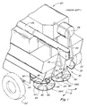
Fig. 1 is a partial perspective view of the rear end of a typical combine with an installed spreader assembly; -
Fig. 2 is a left side view of the rear end of a typical combine according to the invention with an installed spreader assembly that includes side curtains, showing a windrow forming construction mounted at the rear of the combine, with the left side deflector of the windrow forming construction shown partially extended; -
Fig. 3 is a rear, perspective view of an embodiment of the windrow forming construction according toFig 2 . in association with a spreader assembly, such view depicting the spreader plates of the spreader assembly and the windrow forming construction as they might be configured during a swath spreading operation, with the side deflectors of the windrow forming construction shown substantially retracted; -
Fig. 4 is a left side view of a windrow forming construction similar to that depicted inFig. 3 , as installed at the rear of a combine and in association with a spreader assembly, with the side deflectors of the windrow forming construction in substantially retracted positions; -
Fig. 5 is an enlarged left side view of the windrow forming construction ofFig. 4 better illustrating various of the elements and features of such construction; -
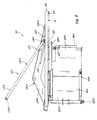
Fig. 6 is a rear, perspective view of an embodiment of a windrow forming construction in association with a spreader assembly, similar in some respects toFig. 3 , but depicting the spreader plates of the spreader assembly and the windrow forming construction as they might be configured for a windrowing operation; -
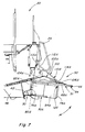
Fig. 7 is a left side view of a windrow forming construction similar to that depicted inFig. 6 , as installed at the rear of a combine and in association with a spreader assembly, with the side deflectors of the windrow forming construction in extended positions; -
Fig. 8 is an enlarged left side view of the windrow forming construction ofFig. 7 better illustrating various of the elements and features of such construction; -
Fig. 9 is an enlarged left side view of a portion of a slot and lock system configuration depicting an alternative arrangement for locking the main body of the windrow forming construction at a desired inclination relative to the ground surface; -
Fig. 10 is an enlarged left side view of a windrow forming construction similar in many respects to that ofFig. 8 but having an alternative positioning mechanism; and -
Fig. 11 is an enlarged left side view of a windrow forming construction similar in many respects to that ofFig. 8 but having a different alternative positioning mechanism. - Referring now to the drawings, wherein like numerals refer to generally like or similar items and wherein certain numerals may be applied on a representational basis to selected, representative items of a class of like items instead of to all of the depicted like items,
Figure 1 depicts the rear portion of atypical combine 20 having a pair ofrear tires 22 mounted upon arear axle 24, with a grain auger or threshingrotor 26, an engineradiator air screen 28, andhandrails 29 mounted upon the upper structure of thecombine 20. Aspreader assembly 30, of well known construction, is mounted generally below a cropresidue discharge chute 32. For safety and other purposes, guard bars 33 are mounted extending generally over and across certain more exposed portions of thespreader assembly 30 and removable drivelinkage cover plates 34 enclose associated drive linkages. When the threshingrotor 26 is operating, crop residue from such operation is discharged intodischarge chute 32 which channels and directs the crop residue flow towards a pair ofspreader head assemblies spreader assembly 30, whichspreader head assemblies - The
spreader head assemblies spreader plate 40 and aspreader cone 42 to which thespreader plates 40 may be joined or secured. Except as may be addressed further hereinafter, thespreader plates 40 for the spreader head assemblies may be considered generally similar to one another, and are shown havingspreader bats 44 mounted on one side thereof, hereinafter referred to as the topside of the spreader plate, with the opposite side generally being substantially flat. - When the
spreader plates 40 are mounted with the topsides up, as depicted inFigure 1 , the spreader assembly is generally considered to be configured for swath spreading. If the spreader plates are re-mounted such that their topsides face downwardly, the spreader assembly is generally considered to be configured for windrowing. As the combine moves through a field during a harvesting operation, crop residue is directed to the cropresidue discharge chute 32 and to thespreader head assemblies spreader assembly 30 to be distributed by the counter-rotation of thespreader head assemblies - In some instances, a user may elect to forego the use of any spreader plates when windrowing is desired. In such event, crop residue is directed to the crop
residue discharge chute 32 and is discharged therefrom to fall to the ground. -
Figures 2-5 are illustrative of the manner in which a windrow forming construction according to the present invention can be employed with acombine 20 and itsspreader assembly 30 and can be configured when swath spreading, as opposed to windrowing, is desired. Rubber or likeside curtains 46 are shown mounted along the sides of thespreader assembly 30, with thewindrow forming construction 50 positioned and connected, as will be addressed in more detail hereinafter, to extend rearwardly from thecombine 20 over the top of thespreader assembly 30, or the area that would be occupied by thespreader assembly 30 in the event that a user elects to forego the use ofspreader plates 40 or a spreader assembly. - As will be appreciated from a further study of
Figures 2-5 , themain body 51 ofwindrow forming construction 50 is dimensioned to extend rearwardly from thecombine 20 to beyond the footprint area of aspreader assembly 30 and laterally across the breadth of such a spreader assembly. The preferred embodiment depicted includes anupper deck 52 within anouter base frame 54 of a generally rectangular racetrack configuration, whichouter base frame 54 is interrupted along its forward portion where the outer base frame is engaged with alignedbrackets 56 at the rear of thecombine 20 for journalled movement. It is clear that alternative executions of theouter base frame 54 are possible, such as for example a generally ovaloid configuration. The left andright forward portions outer base frame 54 are further supported by journal box supports 62 spaced to the sides of thebrackets 56 and positioned relative thereto to permit rotational movement of the thus engaged and supportedouter base frame 54 about a lateral generally horizontal axis ofrotation 64 at the rear of thecombine 20, the height of such mainbody rotation axis 64 defining a frame mounting elevation. Therear portion 66 ofouter base frame 54 extends beyond the spreader assembly footprint, and theoutermost side portions upper deck 52 within theouter base frame 54 extending over the substantial entirety of the spreader assembly footprint to the rear of thecombine 20. - Left and right side deflectors or baffles 70A and 70B are mounted at respective deflector pivot points 72A and 72B at or near the opposite
front sides upper deck 52 to extend generally rearwardly therefrom from pivotally connected first ends 76A and 76B to respective free second ends 78A and 78B and to project downwardly from adjacentupper deck 52 towards the ground surface.Such deflectors side curtains 46 along the front sides of thespreader assembly 30, to permit thedeflectors such deflectors - The
deflectors first portions second portions deflectors - In the embodiment of
Figure 2 ,upper deck 52 is shown as having a somewhat trapezoidal shape, with a wider front portion being disposed generally adjacent to the rear of thecombine 20 and theforward portions outer base frame 54. Inwardly angled portions extend from the sides of the upper deck towards a narrower back portion generally adjacent therear portion 66 of theouter base frame 54, withedge deflectors 95 being attached along the angled portions. Optionally,such edge deflectors 95 may be formed of a flexible or pliable material to accommodate pivotal movement ofdeflectors such edge deflectors 95, as will be further discussed hereinafter, and the upper deck may have a slight downward taper or angle near therear portion 66 ofouter base frame 54 to provide some downward deflection of crop residue at the rear of the windrow forming construction. - A
positioning mechanism 100 includes a pair oflift arms front portions front portions outer base frame 54, andrear portions rear portion 66 of theouter base frame 54. A pair ofsupport arms 110A and 110B, having front ends 112A and 112B connected to the rear of thecombine 20 atelevations rear ends 114A and 114B connected to therear portions respective lift arms Figure 2 thesupport arms 110A and 110B are connected to one another by aninterconnection portion 118 such that thesupport arms 110A and 110B andinterconnection portion 118 define a U-shaped support. - As may be more readily observed from
Figure 5 , when the front ends 112A, 112B of thesupport arms 110A and 110B of the preferred embodiment are connected to fixed positions F on the combine or associated equipment, the rear ends 114A, 114B of such support arms atinterconnection portion 118 may be configured to engageably ride withinslots 120 extending along therear portions lift arms lock niches 122 along the upper sides of theslots 120. Such engagement of thesupport arms 110A and 110B with theslots 120 along therear portions lift arms rear portion 66 of theouter base frame 54 as thewindrow forming construction 50 is rotated about the main body rotation axis 64 (Figure 3 ). As thewindrow forming construction 50 is rotated counterclockwise about the axis ofrotation 64, rear ends 114A and 114B of thesupport arms 110A and 110B are moved rearwardly along theslots 120 and the elevation of therear portion 66 of theouter base frame 54 is increased. As thewindrow forming construction 50 is rotated clockwise about the axis ofrotation 64, the rear ends 114A and 114B of thesupport arms 110A and 110B are moved forwardly along theslots 120 and the elevation of therear portion 66 of theouter base frame 54 is decreased. When the rear ends 114A and 114B of thesupport arms 110A and 110B are moved intocorresponding lock niches 122 along the upper sides of theslots 120, the weight of theouter frame base 54, the associatedupper deck 52, and theside deflectors rear portion 66 of theouter frame base 54 at a given height and themain body 51 at a given inclination relative to the ground surface. - The
slots 120 and lockniches 122 are disposed along the rear ends 106A and 106B of thelift arms support arms 110A and 110B are engaged with and in the most rearward lock niches, theouter frame base 54 extends and is supported generally horizontal to the ground, and when the rear ends 114A and 114B of thesupport arms 110A and 110B are engaged with and in the most forward lock niches, theouter frame base 54 extends almost fully downward, in a service position. By varying the lock niches with which the rear ends of the support arms are engaged, the inclination of themain body 51 may thus be varied, with the various intermediate settings allowing the operator to control to some extent the inclination with which the crop mat is directed towards the ground and the remaining stubble thereupon. - As the inclination of the
main body 51 is thus varied, the deflector rotation axes 80A and 80B will be tilted to some extent, becoming more or less vertical, but remaining generally transverse to the mainbody rotation axis 64. When the rear ends 114A and 114B of thesupport arms 110A and 110B are moved to the most forward positions along theslots 120, themain body 51 is allowed to rotate about the mainbody rotation axis 64 to hang significantly vertically, in a service position, with the deflector rotation axes 80A and 80B then being disposed more horizontally than vertically. The degree to which rotation of themain body 51 about the mainbody rotation axis 64 is allowed will be dependent upon the sizes and dimensions of various elements and components of thecombine 20 andspreader assembly 30, including thespreader plates 40, as well as the position of the frame mounting elevation at the rear of thecombine 20 and the dimensions of the components of thewindrow forming construction 50. Preferably, the degree of permitted rotation will be sufficient to allow easy servicing of elements but less than would result in impingement of thewindrow forming construction 50 or its components with thespreader plates 40 or other elements of thespreader assembly 30. - With the
side deflectors Figure 2 , and theouter base frame 54 locked in a generally horizontal position, the free ends 78A and 78B ofside deflectors spreader assembly 30. With such configuration, thespreader assembly 30 may be operated to effect swath spreading as thespreader plates 40 rotate and the spreader bats 44 onsuch spreader plates 40 propel the crop residue rearwardly and sidewardly in a swath on the field in a well known manner. Optionally, to ensure that the side deflectors remain configured as desired, stop and latching or locking mechanisms may be associated with thedeflectors sides outer base frame 54 to maintain thedeflectors spreader assembly 30. Such latching or locking mechanisms may be of any well known construction suitable for latching or locking thedeflectors bolts 125 with thedeflectors sides outer base frame 54. - When a user determines that, instead of spreading the crop residue in a swath on the field, he desires to discharge the crop residue as a windrow, he would be expected to either reverse the attitude of the
spreader plates 40 such that the relatively flat sides face upwardly and the spreader bats 44 on the opposite sides of the spreader plates face downwardly or to remove the spreader plates entirely. In such event, the windrow forming construction of the present invention can be readily reconfigured, as depicted inFigures 6-8 , to adjust or controllably vary to some extent the lateral width of the windrow and the degree to which the crop residue is blown or thrown into the remaining stubble on the field. -
Figures 6-8 correspond generally toFigures 3-5 but depict a manner in which thewindrow forming construction 50 might be re-configured to establish a desired windrow width and the degree to which the crop residue is to be directed into the stubble remaining on the field during a windrowing operation. As shown inFigure 6 , theside deflectors flexible edge deflectors 95 which may be bent or flexed upwardly to permit the side deflectors to be moved below and past them, and the side deflectors have been extended to a desired extended length, as a consequence of which the spacing between the free ends 78A and 78B ofside deflectors Main body 51 has been rotated about mainbody rotation axis 64 to a desired inclination of themain body 51 relative to the ground surface and locked in position by engaging the rear ends 114A and 114B ofsupport arms 110A and 110B, at interconnection portion 118 (Figure 6 ), inappropriate lock niches 122, as may be best observed fromFigure 8 . Latching or locking mechanisms of any well known construction suitable for latching or locking thedeflectors bolts 125 with thedeflectors upper deck 52, may be utilized to latch or lock the rotated and extendedside deflectors spreader plates 40 of thespreader assembly 30 then installed with the spreader bats 44 facing downwardly and the flat sides of the spreader plates facing upwardly, thespreader assembly 30 can then be operated to propel the crop residue being provided thereto rearwardly where thewindrow forming construction 50 forms and directs the crop residue into a windrow on the field. - Depending upon the desires of the user, the
side deflectors such deflectors - It will be understood by those skilled in the art that the present invention may take a variety of forms other than the particular embodiments described hereinabove and that various features and elements can be achieved through alternate means and constructions. For example,
Figure 9 depicts an alternate slot and lock system configuration that could be readily utilized in place of theslots 120 and lockniches 122 as depicted inFigures 2-8 . In the configuration set forth inFigure 9 , aslot 130 may be disposed in the rear portion of a lift arm and may have associated therewith, instead oflock niches 122 along the top side of the slot, a plurality of lockingpositions 132 along the bottom side of the slot, such that, when the rear end of a support arm is moved into and engaged in alocking position 132, the main body will be supported at a desired inclination relative to the ground surface. -
Figure 10 depicts a left side view of an alternate positioning mechanism that could be employed and which does not requirelift arms position control arm 140A. Since the positioning control arms and other associated elements are of like construction, the following discussion addressing the left position control arm and associated elements will generally also apply to the like right position control arm and its associated like elements.Position control arm 140A includes a first, forward end 142A connected to a slot andlock system 143 installed on thecombine 20 or its associated equipment at an elevation above the frame mounting elevation and a second, rear end 144A coupled torear portion 66 ofouter base frame 54 to permit relative rotational movement of rear end 144A andrear portion 66 about a generally horizontal axis thoughconnector 145. Slot andlock system 143 includes abracket member 148 with a generallyvertical slot 150 extending therealong and having a plurality of spacedlock niches 152 along the extent of theslot 150. By repositioning the forward end 142A ofposition control arm 140A from onelock niche 152 to anotherlock niche 152 along theslot 150, the elevation of therear portion 66 ofouter base frame 54 can be increased or decreased to change the inclination ofmain body 51 relative to the ground surface, as will be readily understood by those in the art, for the same purposes and to the same effect as has been previously addressed herein with respect to operation of thepositioning mechanism 50. - While the positioning mechanisms that have been addressed hereinabove have utilized slot and lock systems of various configurations for varying the inclination of the
main body 51 and supporting suchmain body 51 in a desired position, it will be recognized that the positioning mechanisms of the present invention may also take many forms that do not require or make use of slot and lock systems or like arrangements. By way of example, and not of limitation,Figure 11 depicts one suchother positioning mechanism 50" which utilizes an operator controlledhydraulic cylinder system 160, one end of which is connected to thecombine 20 or associated equipment as atconnector 162 and the other end of which is coupled to theouter frame base 54 as atconnector 164 throughpiston rod 166, which hydraulic cylinder system is responsive to inputs from an operator to control the operation ofpiston rod 166 and, thus, the height of therear portion 66 ofouter base frame 54 and the inclination ofmain body 51 relative to the ground surface. Depending upon characteristics of the windrow forming construction, including its weight and the distribution of such weight, and the positioning of the hydraulic cylinder system, such hydraulic cylinder system may be designed to be either single-acting or double-acting, and could employ multiple cylinders or include load balancing elements. - For various reasons, including stability and balance purposes, many of the positioning mechanisms discussed hereinabove have utilized paired members for controlling the inclination of the
main body 51 of the windrow forming construction and for supporting such construction in a desired position, but it should be appreciated and understood that, depending upon the characteristics of the combine and spreader assembly with which the windrow forming construction is employed, as well as the design characteristics of the windrow forming construction itself, more or fewer elements could be utilized to achieve the desired effect in controlling the inclination of the main body and supporting the windrow forming construction in desired positions without departing from the scope of the invention as defined by the claims. In addition, many elements could be advantageously employed in the positioning mechanisms for adjusting, or controlling the adjustment of, the inclination of the main body relative to the ground surface, including various hydraulic, pneumatic, and electrical motors and control systems in addition to a host of manual adjustment and support systems that can be readily designed and utilized. - Furthermore, it should evident to those skilled in the art that many changes could be made to the main body and to the side deflectors, or variations thereof employed, without departing from the scope of the claims. By way of example and illustration, and not by way of limitation, the main body could be formed as a unitary casting or could be constructed to have a different formation and to have a different superstructure and connection points. Likewise, the side deflectors could employ different types of telescoping or extension arrangements and techniques, as well as a variety of other latching or locking arrangements and techniques for maintaining the deflectors in desired configurations and positions.
- In light of all the foregoing, it should thus be apparent to those skilled in the art that there has been shown and described a windrow forming construction that permits a user of a harvesting combine to adjust or controllably vary to some extent the lateral width of a windrow and preferably the degree to which the crop residue forming the windrow is blown or thrown into the remaining stubble on the field. It will be understood that changes in the details, materials, steps, and arrangements of parts which have been described and illustrated to explain the invention will occur to and may be made by those skilled in the art upon a reading of this disclosure within the scope of the invention as defined by the claims. The foregoing description illustrates the preferred embodiment of the invention; however, concepts, as based upon the description, may be employed in other embodiments without departing from this scope of the invention.
Claims (15)
- A harvesting machine (20) comprising:a rear residue discharge chute (32) for the discharge of crop residue therefrom;a spreader assembly (30) positionable generally below and to the rear of the rear residue discharge chute (32), the spreader assembly (30) defining a spreader a spreader assembly footprint area;a windrow forming construction (50) positionable at the rear of the harvesting machine (20) and comprising a main body (51) mountable to the rear of the harvesting machine (20) in order to extend generally rearwardly from the harvesting machine (20) over the top rear end of the spreader assembly footprint area to a rear portion beyond the rear end of the spreader assembly footprint area and to extend generally laterally across the expanse of the spreader assembly footprint area, the main body (51) comprising opposed front sides (74A, 74B) generally adjacent to the sides of the spreader assembly footprint area,characterised in that the windrow forming construction (50) additionally comprises a pair of side deflectors (70A, 70B) disposed projecting generally downwardly towards the ground surface at said opposed front sides (74A, 74B) of said main body (51) and extending generally along the sides of the spreader assembly footprint area , the side deflectors (70A, 70B) being connected at the opposed front sides (74A, 74B) of the main body (51) to be pivotally rotatable about respective deflector rotation axes (80A, 80B) that are generally parallel to one another and transverse to said main body (51), each of the side deflectors (70A, 70B) having a connected end (76A, 76B) and a free end (78A, 78B), the side deflectors (70A, 70B) being rotatable about their respective deflector rotation axes (80A, 80B) to vary the spacing between the free ends (78A, 78B) of said side deflectors (70A, 70B).
- A harvesting machine according to claim 1, characterised in that the side deflectors (70A, 70B) comprise first portions (82A, 82B) associated with the connected ends (76A, 76B) thereof and second portions (84A, 84B) associated with said free ends (78A, 78B) thereof, the first and second portions (82A, 82B, 84A, 84B) being engaged with one another to be slidable relative to one another to vary the length of the side deflectors (70A, 70B) between a minimum retracted length and a maximum extended length.
- A harvesting machine according to any of the preceding claims, characterised in that the side deflectors (70A, 70B) and the main body (51) comprise mechanisms having portions complementarily engageable with one another to latch the side deflectors (70A, 70B) in place at the desired rotational positionings about their respective deflector rotation axes (80A, 80B)
- A harvesting machine according to any of the preceding claims, characterised in that the main body (51) comprises:an outer base frame (54) having a front portion (60A, 60B) connectable to the harvesting machine (20),a rear portion (66) extending to beyond the rear of the spreader assembly footprint area, andside portions (68A, 68B) extending beyond the sides of the spreader assembly footprint area,an upper deck (52) disposed within the outer base frame (54) extending to cover the substantial entirety of the spreader assembly footprint area.
- A harvesting machine according to any of the preceding claims, characterised in that the upper deck (52) is of a generally trapezoidal shape, having a wider portion generally adjacent the front portion (60A, 60B) of said outer base frame (54) , a narrower portion generally along the rear portion (66) of the outer base frame (54), and side portions extending between the wider and narrower portions, said side portions comprising angled areas having edge deflectors (95) thereat for deflecting crop residue downwardly.
- A harvesting machine according to any of the preceding claims, characterised in that the main body (51) is mountable to the rear of the harvesting machine (20) for rotational movement about a generally horizontal axis of rotation generally laterally transverse to the harvesting machine (20) defining a main body rotation axis (64), and in that a positioning mechanism (100, 50', 50") is operatively connectable to the harvesting machine (20) and to the main body (51) to support said main body (51) at a plurality of rotational positions about said main body rotation axis (64).
- A harvesting machine according to claim 6, characterised in that the positioning mechanism (100) comprises:a pair of lift arms (102A, 102B) connected to said main body (51) to extend generally thereacross from front to rear thereof, the lift arms (102A, 102B) each comprising a slot and lock system therein extending therealong, the slot and lock system comprising a slot (120) and a plurality of locking areas (122) along the slot (120); anda pair of support arms (110A, 110B) having front ends (112A, 112B) operatively connectable to the harvesting machine (20) above the height of the main body rotation axis (64) and rear ends (114A, 114B) engeagable with the slot and lock system, the rear ends (114A, 114B) movable along the slots (120) and positionable within the locking areas (122),whereby movement of the rear ends (114A, 114B) of the support arms (110A, 110B) along the slots (120) effects a rotation of the main body (51) about the main body rotation axis (64) and positioning of the rear ends (114A, 114B) of the support arms (110A, 110B) in corresponding locking areas (122) along the slots (120) latches the main body (51) at a given rotational positioning about the main body rotation axis (64).
- A harvesting machine according to claim 6, characterised in that the positioning mechanism (50') comprises:a slot and lock system operatively mountable to the harvesting machine (20) at a height above the height of said main body rotation axis (64), said slot and lock system including generally vertically extending slots (150) and a plurality of locking areas (152) along said slots (150); anda pair of position control arms (140A) having rear ends (144A) operatively connected to the main body (51) and forward ends (142A) engageable with the slot and lock system, the forward ends (142A) movable along the slot (150) and positionable within the locking areas (152),whereby movement of the forward ends (142A) of the position control arms (140A) along the slots (150) effects a rotation of the main body (51) about the main body rotation axis (64) and positioning of the forward ends (142A) of the support arms (140A) in corresponding locking areas (152) along the slots (150) latches the main body (51) at a given rotational positioning about the main body rotation axis (64).
- A harvesting machine according to claim 6, characterised in that the positioning mechanism (50") comprises at least one arm member operatively connected at one end to the harvesting machine (20) and at the other end to the main body (51) adjacent to the rear portion thereof, the length of the arm member or arm members being adjustable.
- A harvesting machine according to claim 9, characterised in that the arm member or arm members are telescopically adjustable.
- A harvesting machine according to claim 10, characterised in that the arm member or arm members include a hydraulically controllable cylinder system (160).
- A harvesting machine according to any of the claims 6 to 11, characterised in that the positioning mechanism (100, 50', 50") is remotely operable by a user.
- A harvesting machine according to any of the claims 6 to 12, characterised in that the positioning mechanism (100, 50', 50") comprises an electric motor.
- Method for discharging crop residue from a harvesting machine according to any of the preceding claims, characterised in that the rotational positioning of the side deflectors (70A, 70B) about their respective deflector rotation axes (80A, 80B) to a desired position establishes a desired windrow width or swath spreading width of the crop residue.
- Method according to claim 14 for discharging crop residue from a harvesting machine according to any of the claims 6 to 13, characterised in that the rotational positioning of the main body (51) about the main body rotation axis (64) to a desired position establishes a desired inclination at which the crop residue towards is directed to the ground surface.
Applications Claiming Priority (1)
| Application Number | Priority Date | Filing Date | Title |
|---|---|---|---|
| US11/904,980 US7635299B2 (en) | 2007-09-28 | 2007-09-28 | Windrow forming construction |
Publications (2)
| Publication Number | Publication Date |
|---|---|
| EP2042018A1 true EP2042018A1 (en) | 2009-04-01 |
| EP2042018B1 EP2042018B1 (en) | 2010-12-29 |
Family
ID=40243995
Family Applications (1)
| Application Number | Title | Priority Date | Filing Date |
|---|---|---|---|
| EP08165101A Active EP2042018B1 (en) | 2007-09-28 | 2008-09-25 | Windrow forming construction |
Country Status (4)
| Country | Link |
|---|---|
| US (1) | US7635299B2 (en) |
| EP (1) | EP2042018B1 (en) |
| AT (1) | ATE493020T1 (en) |
| DE (1) | DE602008004197D1 (en) |
Cited By (6)
| Publication number | Priority date | Publication date | Assignee | Title |
|---|---|---|---|---|
| EP2340703A1 (en) * | 2010-01-04 | 2011-07-06 | CNH Belgium N.V. | Air curtain discharge protection for an agricultural harvester |
| DE102006042970B4 (en) * | 2006-09-13 | 2014-07-03 | Deere & Company | Combine harvester with a protective hoop associated with the straw chopper and a straw guide rake |
| EP2853143A1 (en) * | 2013-09-30 | 2015-04-01 | Deere & Company | Agricultural combine with windrow control circuit |
| EP3108738A1 (en) * | 2015-06-24 | 2016-12-28 | CNH Industrial Belgium nv | Spreader arrangement with vertically pivoting spread deflector |
| US11432466B2 (en) * | 2019-06-24 | 2022-09-06 | Deere & Company | Windrow system with split curtains and method thereof |
| US20230103977A1 (en) * | 2021-10-01 | 2023-04-06 | Cnh Industrial America Llc | Pivotable windrow chute for combine harvester |
Families Citing this family (23)
| Publication number | Priority date | Publication date | Assignee | Title |
|---|---|---|---|---|
| SE531230C2 (en) | 2007-06-20 | 2009-01-27 | Rekordverken Ab | Combine harvester with outlet fans |
| EP2279654B1 (en) * | 2009-07-28 | 2015-05-20 | CNH Industrial Belgium nv | Spreader disk assembly convertible for windrowing |
| US8876583B2 (en) * | 2009-12-02 | 2014-11-04 | Cnh Industrial America Llc | Regulator of residue flow for spreading devices on agricultural combines |
| US8863489B2 (en) | 2011-03-30 | 2014-10-21 | H & S Manufacturing Co., Inc. | Tine drive cam for windrow merger |
| US8585475B2 (en) * | 2011-04-19 | 2013-11-19 | Cnh America Llc | Crop residue distribution apparatus and system with cooperatively movable deflector door and spreader assembly |
| US9801339B2 (en) * | 2012-05-31 | 2017-10-31 | Cnh Industrial America Llc | Regulator of residue flow for spreading devices on agricultural combines |
| US8574048B1 (en) | 2012-07-10 | 2013-11-05 | Cnh America Llc | Combine spreader arrangement having independently positionable spreader disks |
| US9107349B2 (en) | 2012-08-31 | 2015-08-18 | Cnh Industrial America Llc | System and method for controlling the spreading of crop residue expelled from an agricultural combine |
| US9137944B2 (en) | 2012-08-31 | 2015-09-22 | Cnh Industrial America Llc | Windrow door for an agricultural combine |
| US8992294B2 (en) | 2012-08-31 | 2015-03-31 | Cnh Industrial America Llc | Windrow door assembly for an agricultural combine |
| US9894837B2 (en) * | 2012-10-04 | 2018-02-20 | Cnh Industrial America Llc | Adjustable windrow assembly for an agricultural vehicle |
| US10225987B2 (en) * | 2012-12-12 | 2019-03-12 | Cnh Industrial America Llc | Discharge guide for an agricultural harvester |
| US9554518B2 (en) | 2013-07-03 | 2017-01-31 | Cnh Industrial America Llc | Actuation linkage for flexible crop residue management |
| US10582663B2 (en) | 2013-07-03 | 2020-03-10 | Cnh Industrial America Llc | Cleaning device for an agricultural machine |
| US9357703B2 (en) * | 2013-07-03 | 2016-06-07 | Cnh Industrial America Llc | Pivot support member for agricultural machine |
| CA2897880C (en) * | 2014-07-21 | 2019-09-24 | Dean Mayerle | Apparatus for chopping and discharging straw from a combine harvester |
| US9521808B2 (en) * | 2014-11-19 | 2016-12-20 | Cnh Industrial America Llc | Harvester chaff pan assembly with moveable deflector components |
| BR102016008762B1 (en) * | 2015-04-30 | 2021-06-22 | Cnh Industrial America Llc | crop residue apparatus for crop residue distribution and combined harvester |
| DK3162182T3 (en) * | 2015-10-29 | 2018-05-22 | Kverneland Group Kerteminde As | SWATHING UNIT |
| US10398081B2 (en) * | 2016-12-22 | 2019-09-03 | Cnh Industrial America Llc | Straw spreader and chaff spreader for a combine harvester |
| US11039574B2 (en) * | 2017-09-22 | 2021-06-22 | Deere & Company | System to reduce material accumulation on top of a power residue spreader on an agricultural combine |
| CN112119752B (en) * | 2019-06-24 | 2024-06-28 | 迪尔公司 | Windrow system with split curtains and method thereof |
| EP4541175B1 (en) * | 2023-10-19 | 2026-07-08 | CNH Industrial Belgium N.V. | Movable spreader frame for a harvester |
Citations (2)
| Publication number | Priority date | Publication date | Assignee | Title |
|---|---|---|---|---|
| EP1579755A1 (en) * | 2004-03-24 | 2005-09-28 | Deere & Company | Straw guiding rake |
| EP1716736A1 (en) | 2005-04-28 | 2006-11-02 | Deere & Company | Combine harvester |
Family Cites Families (21)
| Publication number | Priority date | Publication date | Assignee | Title |
|---|---|---|---|---|
| US2854046A (en) * | 1956-06-20 | 1958-09-30 | Arthur F Devorak | Windrowing attachment for combine having a straw chopper |
| US2918776A (en) * | 1956-11-29 | 1959-12-29 | Deere & Co | Windrowing means for crop conditioner |
| US2911780A (en) * | 1957-09-26 | 1959-11-10 | Dale W Brady | Hay conditioning implement |
| AT262680B (en) * | 1961-12-01 | 1968-06-25 | Lely Nv C Van Der | Drum turner |
| US3841070A (en) * | 1972-08-02 | 1974-10-15 | Int Harvester Co | Windrow placement device and harvesting method |
| US3803821A (en) * | 1973-01-18 | 1974-04-16 | Int Harvester Co | Self-adjusting crop deflector |
| US3815823A (en) * | 1973-02-27 | 1974-06-11 | Int Harvester Co | Straw chopper attachment for harvester combines |
| US4532941A (en) * | 1984-08-31 | 1985-08-06 | Gauthier Alfred J | Discharge control attachment for a combine harvester |
| DE3740607A1 (en) | 1987-12-01 | 1989-06-15 | Boeck Xaver | DEVICE FOR SWATHING MAEHGUT |
| FR2627942B1 (en) * | 1988-03-04 | 1990-08-10 | Kuhn Sa | IMPROVEMENT IN AGRICULTURAL MACHINES FOR HARVESTING |
| US5930988A (en) * | 1997-07-18 | 1999-08-03 | Hay & Forage Industries | On-the-go from the tractor seat windrow adjustment |
| DE19906454A1 (en) * | 1999-02-16 | 2000-08-31 | Deere & Co | Distribution device of a shredding device |
| US6251009B1 (en) * | 1999-08-06 | 2001-06-26 | Deere & Company | Straw chopper housing |
| US6238286B1 (en) * | 1999-08-06 | 2001-05-29 | Deere & Company | Crop residue spreader |
| US6616528B2 (en) * | 2001-12-12 | 2003-09-09 | Case Corporation | Vertical crop residue chopper and spreader |
| US6547169B1 (en) * | 2002-06-25 | 2003-04-15 | Case Corporation | Crop residue spreader for an agricultural combine |
| CA2427755A1 (en) * | 2003-05-05 | 2004-11-05 | Macdon Industries Ltd. | Windrow forming system for a crop harvesting header |
| CA2470876C (en) * | 2004-06-14 | 2009-12-08 | Redekop Chaff Systems Ltd. | Combine harvester with ready adjustment of discharge positions of straw and chaff |
| US20060123764A1 (en) | 2004-12-09 | 2006-06-15 | Mclean Kenneth W | Adjustable windrower shields |
| US7261633B2 (en) * | 2005-02-15 | 2007-08-28 | Cnh America Llc | Unitary pivoting spreader apparatus |
| US7331855B2 (en) * | 2005-07-15 | 2008-02-19 | Deere & Company | Wide-spread impeller spreader for harvesting combine |
-
2007
- 2007-09-28 US US11/904,980 patent/US7635299B2/en not_active Expired - Fee Related
-
2008
- 2008-09-25 DE DE602008004197T patent/DE602008004197D1/en active Active
- 2008-09-25 AT AT08165101T patent/ATE493020T1/en not_active IP Right Cessation
- 2008-09-25 EP EP08165101A patent/EP2042018B1/en active Active
Patent Citations (2)
| Publication number | Priority date | Publication date | Assignee | Title |
|---|---|---|---|---|
| EP1579755A1 (en) * | 2004-03-24 | 2005-09-28 | Deere & Company | Straw guiding rake |
| EP1716736A1 (en) | 2005-04-28 | 2006-11-02 | Deere & Company | Combine harvester |
Cited By (9)
| Publication number | Priority date | Publication date | Assignee | Title |
|---|---|---|---|---|
| DE102006042970B4 (en) * | 2006-09-13 | 2014-07-03 | Deere & Company | Combine harvester with a protective hoop associated with the straw chopper and a straw guide rake |
| EP2340703A1 (en) * | 2010-01-04 | 2011-07-06 | CNH Belgium N.V. | Air curtain discharge protection for an agricultural harvester |
| EP2853143A1 (en) * | 2013-09-30 | 2015-04-01 | Deere & Company | Agricultural combine with windrow control circuit |
| US9668418B2 (en) | 2013-09-30 | 2017-06-06 | Deere & Company | Agricultural combine with windrow control circuit |
| EP3108738A1 (en) * | 2015-06-24 | 2016-12-28 | CNH Industrial Belgium nv | Spreader arrangement with vertically pivoting spread deflector |
| US10694667B2 (en) | 2015-06-24 | 2020-06-30 | Cnh Industrial America Llc | Spreader arrangement with vertically pivoting spread deflector |
| US11432466B2 (en) * | 2019-06-24 | 2022-09-06 | Deere & Company | Windrow system with split curtains and method thereof |
| US20230103977A1 (en) * | 2021-10-01 | 2023-04-06 | Cnh Industrial America Llc | Pivotable windrow chute for combine harvester |
| US12004447B2 (en) * | 2021-10-01 | 2024-06-11 | Cnh Industrial America Llc | Pivotable windrow chute for combine harvester |
Also Published As
| Publication number | Publication date |
|---|---|
| EP2042018B1 (en) | 2010-12-29 |
| US20090088231A1 (en) | 2009-04-02 |
| ATE493020T1 (en) | 2011-01-15 |
| US7635299B2 (en) | 2009-12-22 |
| DE602008004197D1 (en) | 2011-02-10 |
Similar Documents
| Publication | Publication Date | Title |
|---|---|---|
| EP2042018B1 (en) | Windrow forming construction | |
| EP2138026B1 (en) | An agricultural combine comprising a gas spring safety system | |
| EP1576868B1 (en) | Grain storage tank extension for a harvester | |
| EP2702853B1 (en) | Windrow door for an agricultural combine | |
| CA2298988C (en) | Crop residue spreader | |
| CA2309799C (en) | Straw chopper housing | |
| CA2470876C (en) | Combine harvester with ready adjustment of discharge positions of straw and chaff | |
| US10568267B2 (en) | Harvester separation frame orientation adjustment | |
| EP2890235B1 (en) | Windrow door assembly for an agricultural combine | |
| EP3108738A1 (en) | Spreader arrangement with vertically pivoting spread deflector | |
| US12495732B2 (en) | Adjustable spreader system for an agricultural harvester | |
| EP2055177A1 (en) | Adjustable vane system for an axial flow rotor housing of an agricultural combine | |
| EP2145528A1 (en) | Flexible louver opening adjustment mechanism for a pivoting combine harvester cleaning shoe | |
| US4526180A (en) | Straw chopper and spreader assembly | |
| IL47385A (en) | Apparatus for collecting combine waste | |
| CN112119752A (en) | Stacking system with separating curtain and method thereof | |
| US12582034B2 (en) | Crop residue distributor assembly for a combine harvester | |
| US20240099192A1 (en) | Combine harvester cleaning system with finger auger | |
| BR102022022073A2 (en) | SPREADING SYSTEM FOR A SELF-PROPELLED AGRICULTURAL HARVESTER AND SELF-PROPELLED AGRICULTURAL HARVESTER |
Legal Events
| Date | Code | Title | Description |
|---|---|---|---|
| PUAI | Public reference made under article 153(3) epc to a published international application that has entered the european phase |
Free format text: ORIGINAL CODE: 0009012 |
|
| AK | Designated contracting states |
Kind code of ref document: A1 Designated state(s): AT BE BG CH CY CZ DE DK EE ES FI FR GB GR HR HU IE IS IT LI LT LU LV MC MT NL NO PL PT RO SE SI SK TR |
|
| AX | Request for extension of the european patent |
Extension state: AL BA MK RS |
|
| 17P | Request for examination filed |
Effective date: 20091001 |
|
| 17Q | First examination report despatched |
Effective date: 20091028 |
|
| AKX | Designation fees paid |
Designated state(s): AT BE BG CH CY CZ DE DK EE ES FI FR GB GR HR HU IE IS IT LI LT LU LV MC MT NL NO PL PT RO SE SI SK TR |
|
| GRAP | Despatch of communication of intention to grant a patent |
Free format text: ORIGINAL CODE: EPIDOSNIGR1 |
|
| GRAS | Grant fee paid |
Free format text: ORIGINAL CODE: EPIDOSNIGR3 |
|
| GRAA | (expected) grant |
Free format text: ORIGINAL CODE: 0009210 |
|
| AK | Designated contracting states |
Kind code of ref document: B1 Designated state(s): AT BE BG CH CY CZ DE DK EE ES FI FR GB GR HR HU IE IS IT LI LT LU LV MC MT NL NO PL PT RO SE SI SK TR |
|
| REG | Reference to a national code |
Ref country code: GB Ref legal event code: FG4D |
|
| REG | Reference to a national code |
Ref country code: CH Ref legal event code: EP |
|
| REG | Reference to a national code |
Ref country code: IE Ref legal event code: FG4D |
|
| REF | Corresponds to: |
Ref document number: 602008004197 Country of ref document: DE Date of ref document: 20110210 Kind code of ref document: P |
|
| REG | Reference to a national code |
Ref country code: DE Ref legal event code: R096 Ref document number: 602008004197 Country of ref document: DE Effective date: 20110210 |
|
| REG | Reference to a national code |
Ref country code: NL Ref legal event code: VDEP Effective date: 20101229 |
|
| PG25 | Lapsed in a contracting state [announced via postgrant information from national office to epo] |
Ref country code: LT Free format text: LAPSE BECAUSE OF FAILURE TO SUBMIT A TRANSLATION OF THE DESCRIPTION OR TO PAY THE FEE WITHIN THE PRESCRIBED TIME-LIMIT Effective date: 20101229 |
|
| LTIE | Lt: invalidation of european patent or patent extension |
Effective date: 20101229 |
|
| PG25 | Lapsed in a contracting state [announced via postgrant information from national office to epo] |
Ref country code: CY Free format text: LAPSE BECAUSE OF FAILURE TO SUBMIT A TRANSLATION OF THE DESCRIPTION OR TO PAY THE FEE WITHIN THE PRESCRIBED TIME-LIMIT Effective date: 20101229 Ref country code: LV Free format text: LAPSE BECAUSE OF FAILURE TO SUBMIT A TRANSLATION OF THE DESCRIPTION OR TO PAY THE FEE WITHIN THE PRESCRIBED TIME-LIMIT Effective date: 20101229 Ref country code: AT Free format text: LAPSE BECAUSE OF FAILURE TO SUBMIT A TRANSLATION OF THE DESCRIPTION OR TO PAY THE FEE WITHIN THE PRESCRIBED TIME-LIMIT Effective date: 20101229 Ref country code: FI Free format text: LAPSE BECAUSE OF FAILURE TO SUBMIT A TRANSLATION OF THE DESCRIPTION OR TO PAY THE FEE WITHIN THE PRESCRIBED TIME-LIMIT Effective date: 20101229 Ref country code: BG Free format text: LAPSE BECAUSE OF FAILURE TO SUBMIT A TRANSLATION OF THE DESCRIPTION OR TO PAY THE FEE WITHIN THE PRESCRIBED TIME-LIMIT Effective date: 20110329 Ref country code: SE Free format text: LAPSE BECAUSE OF FAILURE TO SUBMIT A TRANSLATION OF THE DESCRIPTION OR TO PAY THE FEE WITHIN THE PRESCRIBED TIME-LIMIT Effective date: 20101229 Ref country code: SI Free format text: LAPSE BECAUSE OF FAILURE TO SUBMIT A TRANSLATION OF THE DESCRIPTION OR TO PAY THE FEE WITHIN THE PRESCRIBED TIME-LIMIT Effective date: 20101229 Ref country code: HR Free format text: LAPSE BECAUSE OF FAILURE TO SUBMIT A TRANSLATION OF THE DESCRIPTION OR TO PAY THE FEE WITHIN THE PRESCRIBED TIME-LIMIT Effective date: 20101229 |
|
| PG25 | Lapsed in a contracting state [announced via postgrant information from national office to epo] |
Ref country code: ES Free format text: LAPSE BECAUSE OF FAILURE TO SUBMIT A TRANSLATION OF THE DESCRIPTION OR TO PAY THE FEE WITHIN THE PRESCRIBED TIME-LIMIT Effective date: 20110409 Ref country code: GR Free format text: LAPSE BECAUSE OF FAILURE TO SUBMIT A TRANSLATION OF THE DESCRIPTION OR TO PAY THE FEE WITHIN THE PRESCRIBED TIME-LIMIT Effective date: 20110330 Ref country code: CZ Free format text: LAPSE BECAUSE OF FAILURE TO SUBMIT A TRANSLATION OF THE DESCRIPTION OR TO PAY THE FEE WITHIN THE PRESCRIBED TIME-LIMIT Effective date: 20101229 Ref country code: PT Free format text: LAPSE BECAUSE OF FAILURE TO SUBMIT A TRANSLATION OF THE DESCRIPTION OR TO PAY THE FEE WITHIN THE PRESCRIBED TIME-LIMIT Effective date: 20110429 Ref country code: IS Free format text: LAPSE BECAUSE OF FAILURE TO SUBMIT A TRANSLATION OF THE DESCRIPTION OR TO PAY THE FEE WITHIN THE PRESCRIBED TIME-LIMIT Effective date: 20110429 Ref country code: NO Free format text: LAPSE BECAUSE OF FAILURE TO SUBMIT A TRANSLATION OF THE DESCRIPTION OR TO PAY THE FEE WITHIN THE PRESCRIBED TIME-LIMIT Effective date: 20110329 Ref country code: EE Free format text: LAPSE BECAUSE OF FAILURE TO SUBMIT A TRANSLATION OF THE DESCRIPTION OR TO PAY THE FEE WITHIN THE PRESCRIBED TIME-LIMIT Effective date: 20101229 |
|
| PG25 | Lapsed in a contracting state [announced via postgrant information from national office to epo] |
Ref country code: SK Free format text: LAPSE BECAUSE OF FAILURE TO SUBMIT A TRANSLATION OF THE DESCRIPTION OR TO PAY THE FEE WITHIN THE PRESCRIBED TIME-LIMIT Effective date: 20101229 Ref country code: NL Free format text: LAPSE BECAUSE OF FAILURE TO SUBMIT A TRANSLATION OF THE DESCRIPTION OR TO PAY THE FEE WITHIN THE PRESCRIBED TIME-LIMIT Effective date: 20101229 Ref country code: RO Free format text: LAPSE BECAUSE OF FAILURE TO SUBMIT A TRANSLATION OF THE DESCRIPTION OR TO PAY THE FEE WITHIN THE PRESCRIBED TIME-LIMIT Effective date: 20101229 Ref country code: PL Free format text: LAPSE BECAUSE OF FAILURE TO SUBMIT A TRANSLATION OF THE DESCRIPTION OR TO PAY THE FEE WITHIN THE PRESCRIBED TIME-LIMIT Effective date: 20101229 |
|
| PG25 | Lapsed in a contracting state [announced via postgrant information from national office to epo] |
Ref country code: DK Free format text: LAPSE BECAUSE OF FAILURE TO SUBMIT A TRANSLATION OF THE DESCRIPTION OR TO PAY THE FEE WITHIN THE PRESCRIBED TIME-LIMIT Effective date: 20101229 |
|
| PLBE | No opposition filed within time limit |
Free format text: ORIGINAL CODE: 0009261 |
|
| STAA | Information on the status of an ep patent application or granted ep patent |
Free format text: STATUS: NO OPPOSITION FILED WITHIN TIME LIMIT |
|
| 26N | No opposition filed |
Effective date: 20110930 |
|
| REG | Reference to a national code |
Ref country code: DE Ref legal event code: R097 Ref document number: 602008004197 Country of ref document: DE Effective date: 20110930 |
|
| PG25 | Lapsed in a contracting state [announced via postgrant information from national office to epo] |
Ref country code: MC Free format text: LAPSE BECAUSE OF NON-PAYMENT OF DUE FEES Effective date: 20110930 |
|
| REG | Reference to a national code |
Ref country code: IE Ref legal event code: MM4A |
|
| PG25 | Lapsed in a contracting state [announced via postgrant information from national office to epo] |
Ref country code: IE Free format text: LAPSE BECAUSE OF NON-PAYMENT OF DUE FEES Effective date: 20110925 |
|
| PG25 | Lapsed in a contracting state [announced via postgrant information from national office to epo] |
Ref country code: MT Free format text: LAPSE BECAUSE OF FAILURE TO SUBMIT A TRANSLATION OF THE DESCRIPTION OR TO PAY THE FEE WITHIN THE PRESCRIBED TIME-LIMIT Effective date: 20101229 |
|
| REG | Reference to a national code |
Ref country code: CH Ref legal event code: PL |
|
| PG25 | Lapsed in a contracting state [announced via postgrant information from national office to epo] |
Ref country code: LU Free format text: LAPSE BECAUSE OF NON-PAYMENT OF DUE FEES Effective date: 20110925 |
|
| PG25 | Lapsed in a contracting state [announced via postgrant information from national office to epo] |
Ref country code: CH Free format text: LAPSE BECAUSE OF NON-PAYMENT OF DUE FEES Effective date: 20120930 Ref country code: LI Free format text: LAPSE BECAUSE OF NON-PAYMENT OF DUE FEES Effective date: 20120930 |
|
| PG25 | Lapsed in a contracting state [announced via postgrant information from national office to epo] |
Ref country code: TR Free format text: LAPSE BECAUSE OF FAILURE TO SUBMIT A TRANSLATION OF THE DESCRIPTION OR TO PAY THE FEE WITHIN THE PRESCRIBED TIME-LIMIT Effective date: 20101229 |
|
| PG25 | Lapsed in a contracting state [announced via postgrant information from national office to epo] |
Ref country code: HU Free format text: LAPSE BECAUSE OF FAILURE TO SUBMIT A TRANSLATION OF THE DESCRIPTION OR TO PAY THE FEE WITHIN THE PRESCRIBED TIME-LIMIT Effective date: 20101229 |
|
| REG | Reference to a national code |
Ref country code: DE Ref legal event code: R082 Ref document number: 602008004197 Country of ref document: DE Representative=s name: PATENTANWAELTE WALLACH, KOCH & PARTNER, DE |
|
| REG | Reference to a national code |
Ref country code: DE Ref legal event code: R082 Ref document number: 602008004197 Country of ref document: DE Representative=s name: PATENTANWAELTE WALLACH, KOCH, DR. HAIBACH, FEL, DE Effective date: 20140428 Ref country code: DE Ref legal event code: R081 Ref document number: 602008004197 Country of ref document: DE Owner name: CNH INDUSTRIAL BELGIUM NV, BE Free format text: FORMER OWNER: CNH BELGIUM NV, ZEDELGEM, BE Effective date: 20140428 Ref country code: DE Ref legal event code: R082 Ref document number: 602008004197 Country of ref document: DE Representative=s name: PATENTANWAELTE WALLACH, KOCH & PARTNER, DE Effective date: 20140428 |
|
| REG | Reference to a national code |
Ref country code: FR Ref legal event code: CD Owner name: CNH INDUSTRIAL BELGIUM NV Effective date: 20140725 |
|
| REG | Reference to a national code |
Ref country code: FR Ref legal event code: PLFP Year of fee payment: 9 |
|
| REG | Reference to a national code |
Ref country code: FR Ref legal event code: PLFP Year of fee payment: 10 |
|
| REG | Reference to a national code |
Ref country code: FR Ref legal event code: PLFP Year of fee payment: 11 |
|
| PGFP | Annual fee paid to national office [announced via postgrant information from national office to epo] |
Ref country code: BE Payment date: 20190925 Year of fee payment: 12 |
|
| PGFP | Annual fee paid to national office [announced via postgrant information from national office to epo] |
Ref country code: GB Payment date: 20190926 Year of fee payment: 12 |
|
| REG | Reference to a national code |
Ref country code: DE Ref legal event code: R084 Ref document number: 602008004197 Country of ref document: DE |
|
| REG | Reference to a national code |
Ref country code: DE Ref legal event code: R082 Ref document number: 602008004197 Country of ref document: DE Representative=s name: MEISSNER BOLTE PATENTANWAELTE RECHTSANWAELTE P, DE |
|
| GBPC | Gb: european patent ceased through non-payment of renewal fee |
Effective date: 20200925 |
|
| REG | Reference to a national code |
Ref country code: BE Ref legal event code: MM Effective date: 20200930 |
|
| PG25 | Lapsed in a contracting state [announced via postgrant information from national office to epo] |
Ref country code: BE Free format text: LAPSE BECAUSE OF NON-PAYMENT OF DUE FEES Effective date: 20200930 Ref country code: GB Free format text: LAPSE BECAUSE OF NON-PAYMENT OF DUE FEES Effective date: 20200925 |
|
| PGFP | Annual fee paid to national office [announced via postgrant information from national office to epo] |
Ref country code: IT Payment date: 20240924 Year of fee payment: 17 |
|
| PGFP | Annual fee paid to national office [announced via postgrant information from national office to epo] |
Ref country code: DE Payment date: 20250926 Year of fee payment: 18 |
|
| PGFP | Annual fee paid to national office [announced via postgrant information from national office to epo] |
Ref country code: FR Payment date: 20250925 Year of fee payment: 18 |
|
| PG25 | Lapsed in a contracting state [announced via postgrant information from national office to epo] |
Ref country code: IT Free format text: LAPSE BECAUSE OF NON-PAYMENT OF DUE FEES Effective date: 20250925 |