EP2041405B1 - Hydraulically operated valve control system and internal combustion engine comprising such a system - Google Patents
Hydraulically operated valve control system and internal combustion engine comprising such a system Download PDFInfo
- Publication number
- EP2041405B1 EP2041405B1 EP06847232A EP06847232A EP2041405B1 EP 2041405 B1 EP2041405 B1 EP 2041405B1 EP 06847232 A EP06847232 A EP 06847232A EP 06847232 A EP06847232 A EP 06847232A EP 2041405 B1 EP2041405 B1 EP 2041405B1
- Authority
- EP
- European Patent Office
- Prior art keywords
- valve
- flow
- throttle
- pressure
- oil
- Prior art date
- Legal status (The legal status is an assumption and is not a legal conclusion. Google has not performed a legal analysis and makes no representation as to the accuracy of the status listed.)
- Not-in-force
Links
- 238000002485 combustion reaction Methods 0.000 title claims description 14
- 238000011144 upstream manufacturing Methods 0.000 claims description 16
- 239000012530 fluid Substances 0.000 claims description 5
- 230000007423 decrease Effects 0.000 description 11
- 239000000446 fuel Substances 0.000 description 3
- 238000010276 construction Methods 0.000 description 2
- 238000006073 displacement reaction Methods 0.000 description 2
- 238000001914 filtration Methods 0.000 description 2
- 238000004519 manufacturing process Methods 0.000 description 2
- 238000004891 communication Methods 0.000 description 1
- 239000007789 gas Substances 0.000 description 1
- 238000002347 injection Methods 0.000 description 1
- 239000007924 injection Substances 0.000 description 1
- 239000000203 mixture Substances 0.000 description 1
- 238000005086 pumping Methods 0.000 description 1
- 230000001360 synchronised effect Effects 0.000 description 1
Images




Classifications
-
- F—MECHANICAL ENGINEERING; LIGHTING; HEATING; WEAPONS; BLASTING
- F01—MACHINES OR ENGINES IN GENERAL; ENGINE PLANTS IN GENERAL; STEAM ENGINES
- F01L—CYCLICALLY OPERATING VALVES FOR MACHINES OR ENGINES
- F01L9/00—Valve-gear or valve arrangements actuated non-mechanically
- F01L9/10—Valve-gear or valve arrangements actuated non-mechanically by fluid means, e.g. hydraulic
Definitions
- This invention concerns an hydraulically operated valve control system for an internal combustion engine. It also concerns an internal combustion engine equipped with such a system.
- EP-A-0 736 671 teaches the use of balancing springs which engage a piston fast with each valve in order to move each valve towards a closing position. Such an approach works if the friction forces for each valve and the rigidity of the two springs are identical and if the hydraulic feeding circuits are symmetrical. Such conditions cannot be guaranteed because of the tolerances in the fabrication of the valves, in the fabrication of the springs and in the distribution of the fluids circuits within a cylinder head. Therefore, it is not sure the two valves of the prior art actually have the same movements.
- US-A-5 619 965 discloses an arrangement for balancing valves in a hydraulic camless valve train.
- Valve position sensors are used in conjunction with an electronic control unit to pilot opening and closing of solenoid valves.
- Such an arrangement is complex and expensive since it requires sensors and solenoid valves dedicated to each inlet valve/exhaust valve of the engine.
- EP 0 767 295 discloses an arrangement comprising a stepped hydraulic synchronising piston, in order to ensure synchronised opening and closing of valves.
- the invention aims at providing an hydraulically operated valve control system which efficiently controls the movements of two valves, without requiring electronic sensors or other complex and expensive equipments.
- the invention concerns an hydraulic operated valve control system for an internal combustion engine having at least one cylinder provided with two valves driven with oil coming from a source of oil under pressure, each valve being controlled by an hydraulic actuator fed with oil under pressure through a respective feeding line.
- This system is characterized in that it includes an hydraulic flow divider comprising an hydraulic valve adapted to distribute the flow of oil coming either from said source or from said two feeding lines between said two feeding lines, depending on the ratio of oil flow-rates in these two lines.
- the hydraulic valve can evenly distribute oil to the two inlet valves or two exhaust valves when these valves are supposed to be lifted.
- the flow divider of the system of the invention accommodates evenly the two flows coming from the two inlet or exhaust valves.
- control system might incorporate one or several of the following features:
- the invention also concerns an internal combustion engine provided with a control system as mentioned here above.
- the camless internal combustion engine E schematically represented on figure 1 comprises several cylinders.
- One cylinder 1 is partly represented and a piston 2 is slidably movable within cylinder 1.
- a combustion chamber 3 is defined between a front face 2a of piston 2 and cylinder head 4.
- Two inlet ducts 11 and 21 are mounted on cylinder head 4 to feed combustion chamber 3 with fuel.
- the flow of fuel within ducts 11 and 21 is controlled by two inlet valves 12 and 22 urged to a closed position by two springs 13 and 23 and piloted each by an hydraulic actuator 14 or 24.
- Each actuator 14 or 24 is fed with oil under pressure through a respective feeding line 15 or 25.
- a hydraulic flow divider 101 is provided to selectively provide actuators 14 and 24 with oil under pressure when it is necessary to open valves 12 and 22.
- Divider 101 is piloted by an electronic control unit 102 and fed with oil under pressure via a main feeding line 103 which comes from a filtration unit 104 fed by a pump 105 pumping oil in a sump 106.
- a main exhaust line 107 conveys oil from divider 101 back to sump 106.
- Oil coming from pump 105 has a pressure between about 70 and about 210 bars.
- Cylinder 1 is provided with some other non represented valves, at least an exhaust valve.
- electronic control unit 102 sends to flow divider 101, an electric signal S 1 , via an electric line 1021.
- Flow divider 101 converts this signal into a double pressure hydraulic signal S 12 , S 22 adapted to control actuators 14 and 24 in order to lift valves 12 and 22 with respect to their respective seats 16 and 26.
- flow divider 101 comprises an hydraulic valve 110 connected to line 103 via a first solenoid valve 117 and to line 107 via a second solenoid valve 118.
- valves 117 isolates hydraulic valve 110 from main feeding line 103 and valve 118 connects hydraulic valve 110 to main exhaust line 107.
- the outlet port of valve 117 and the inlet port of valve 118 are respectively connected to hydraulic valve 110 via a common line 35.
- solenoid valve 117 When solenoid valve 117 is activated to allow communication between line 103 and valve 110, a main flow of oil under pressure flows from line 103 to hydraulic valve 110 with a flow-rate F 0 .
- This flow-rate is divided by hydraulic valve 110 into two secondary flow-rates F 1 and F 2 which convey respectively hydraulic signal S 12 and S 22 .
- Figure 3A shows the part of electrical signal S 1 sent by unit 102 to solenoid valve 117 as a function of time t.
- figure 3B shows, as a function of time t, the part of signal S 118 sent to solenoid valve 118.
- Signals S 117 and S 118 are sent from an instant to, respectively for a first period of time ⁇ t 117 and for a second period time ⁇ t 118 .
- FIG. 3C shows the flow-rate F 0 in line 35 as a result of the opening and closing of solenoid valves 117 and 118.
- F 0 is positive when oil flows from valve 117 to valve 110 and negative when oil flows from valve 110 to valve 118.
- FIG. 3D shows the values of flow-rates F 1 and F 2 in lines 15 and 25, respectively. These values are kept substantially identical, as explained here-under.
- figure 3E shows, the lifts L 11 and L 12 of valves 11 and 12 as a result of flow-rates F 1 and F 2 .
- lifts L 11 and L 12 are identical or superimposed on figure 3E , that is in order to have parallel movements of valves 11 and 12, flow-rates F 1 and F 2 must be substantially identical.
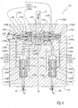
- hydraulic valve 110 is constituted as shown on figures 4 and 5 .
- Valve 110 comprises a valve body 1101 which defines a main bore 1102 extending along the direction of an axis X 2 .
- a valve member 1103 in the form of a spool is slidably mounted within bore 1102 and comprises a main portion 1103A and two lateral portions 1103 1 and 1103 2 , axially secured to main portion 1103A thanks to two locking rings 1103B and 1103C.
- spool 1103 is compressed between two springs 1104 1 and 1104 2 which tend to return spool 1103 to a central position, within bore 1102. It is possible to adjust the central position of spool 1103 within bore 1102 thanks to an adjusting screw 1105 which defines the reference surface of spring 1104 1 on its side opposite to spool 1103.
- Main portion 1103A comprises a central rod 1103D whose diameter D 1 is significantly smaller than the diameter D 2 of the central part 1102A of bore 1102 which communicates with line 35.
- bore 1102 is provided with two grooves 1102 1 and 1102 2 whose diameter D' 2 ' is substantially larger than the maximum diameter D 3 of spool 1103.
- V 1 the volume of groove 1102 1 and of the part of bore 1102 which surrounds central rod 1103D at the axial level of this groove.
- V 2 the volume of groove 1102 2 and the portion of bore 1102 which surrounds rod 1103D at the axial level this groove.
- volume V 1 is smaller, equal or larger than volume V 2 . More precisely, volumes V 1 and V 2 are substantially equal on figure 4 and, if spool 1103 moves towards the left on this figure, volume V 1 becomes larger than volume V 2 .
- volumes V 1 and V 2 are fed with oil under pressure by the oil flow, as shown by arrows F, when solenoid valve 111 is activated.
- the main flow of oil having flow-rate F 0 , divides itself into two secondary flows having each a flow-rate F 1 or F 2 .
- F 0 F 1 + F 2
- a first conduit 1106 1 connects volume V 1 to a bore 1107 1 where a shuttle 1108 1 is movable along a longitudinal axis X 71 of bore 1107 1 .
- Shuttle 1108 1 is provided with a central longitudinal bore 1109 1 which defines a canal for the flow of oil F coming from line 1106 1 . This oil flow exits bore 1107 1 through an exhaust conduit 1110 1 which is connected to line 15.
- a throttle 1111 1 is defined within central bore 1109 1 and this throttle creates a pressure drop in bore 1109 1 when oil flows from conduit 1106 1 towards conduit 1110 1 with flow-rate F 1 .
- a conduit 1106 2 leads from volume V 2 to a bore 1107 2 where a shuttle 1108 2 is slidably movable along a longitudinal axis X 72 of this bore. Bore 1107 2 is connected by an exhaust conduit 1110 2 to line 25. A throttle 1111 2 is defined in a central bore 1109 2 of shuttle 1108 2 .
- Conduit 1106 1 , bores 1107 1 and 1109 1 and conduit 1110 1 form together a connecting line CL 1 between bore 1102 and feeding line 15.
- conduits 1106 2 and 1110 2 and bores 1107 2 and 1109 2 form together a connecting line CL 2 between bore 1102 and line 25.
- a first chamber 1102B is defined between portion 1103 1 and screw 1105.
- a second chamber 1102C is defined around portion 1103 1 and is limited by a first end surface 1103A 1 of portion 1103A. Pressure within chambers 1102B and 1102C acts on the end surface of portion 1103 1 and on surface 1103A 1 to push spool 1103 against the action of spring 1104 2 , that is towards to right on figure 4 , in the direction of arrow A 1 .
- a third chamber 1102D is defined around the free end of lateral portion 1103 2 and a fourth chamber 1102E is defined around portion 1103 2 and limited by a second end surface 1103A 2 of portion 1103. Pressure within chambers 1102D and 1102E tends to push spool 1103 against the action of spring 1104 1 , that is towards the left on figure 4 , in the direction of arrow A 2 .
- Chambers 1102B and 1102D, on the one hand, and chambers 1102C and 1102E, on the other hand, are symmetrical with respect to a central axis X 1 of body 1101.
- Shuttle 1108 1 is provided with a first external groove 1112A and a second external groove 1112B offset axially with respect to groove 1112A.
- Groove 1112A is connected to central bore 1109 1 via a first canal 1112C
- groove 1112B is connected to central bore 1109 1 via a second canal 1112D.
- Canals 1112C and 1112D are located on either sides of throttle 1111 1 .
- shuttle 1108 2 is provided with two external grooves 1122A and 1122B and two canals 1122C and 1122D located axially on either sides of throttle 1111 2 .
- groove 1112A is aligned with the outlet of a conduit 1125A which extends between bore 1107 1 and chamber 1102B.
- groove 1112B is located in front of one of the two outlets of a conduit 1125B which connects bore 1107 1 to chamber 1102E.
- a third conduit 1125C has its outlet located in front of groove 1122A when shuttle 1108 2 is in the position of figure 4 and connects bore 1107 2 to chamber 1102D.
- a fourth conduit 1125D has two outlets in bore 1107 2 , one of these outlets being located at the level of groove 1122B in the configuration of figure 4 .
- Connecting line 1125D connects bore 1107 2 to chamber 1102C.
- hydraulic valve 110 The construction of hydraulic valve 110 is such that flow-rates F 1 and F 2 are automatically adjusted to be equal, so that actuators 14 and 24 are driven in the same manner.
- flow-rate F 1 is the same in connecting line CL 1 and in feeding line 15.
- flow-rate F 2 is the same in connecting line CL 2 and feeding line 25.
- portion 1103 2 has the same area as surface 1103A 2 which undergoes the pressure within chamber 1102E. Therefore, because of the pressure differences between chambers 1102B and 1102E, on the one hand, and 1102D and 1102C, on the other hand, spool 1103 is pushed to the right of figure 4 in direction of arrow A 1 , that is against the action of spring 1104 2 .
- volume V 1 decreases
- volume V 2 increases so that the cross section of volume V 1 available for oil flow F 1 becomes smaller than the cross section of volume V 2 available for oil flow F 2 .
- flow-rate F 1 in line 1106 1 decreases and flow-rate F 2 in line 1106 2 increases. Therefore, ratio R decreases up to when it reaches value "1".
- flow-rate F 2 tends to be larger than flow-rate F 1 , that is if R is smaller than 1, the pressure differences work in the other way, so that spool 1103 is moved to the left on figure 4 in the direction of arrow A 2 and the cross section of volume V 2 available for flow-rate F 2 decreases whereas the cross section of volume V 1 available for flow-rate F 1 increases, so that R increases up to when it reaches the values "1".
- hydraulic valve 110 evenly distributes flow-rate F 0 into two substantially equal flow-rates F 1 and F 2 whose ratio R equals "1" or is automatically adjusted to "1", so that actuators 14 and 24 are driven in the same way.
- shuttles 1108 1 and 1108 2 lie respectively against second end walls 1114 1 and 1114 2 of bores 1107 1 and 1107 2 on the sides of lines 1106 1 and 1106 2 , that is opposite lines 15 and 25.
- groove 1112B is connected by conduit 1125A to chamber 1102B.
- groove 1112A is connected via conduit 1125B to chamber 1102E.
- canals 1112C and 1112D chamber 1112B is at the pressure within central bore 1109 1 upstream of throttle 1111 1
- chamber 1102E is at the pressure within central bore 1109 1 downstream of throttle 1111 1 .
- the pressure difference between chambers 1102B and 1102E measures the pressure drop at the level of throttle 1111 1 , as in the configuration of figure 4 .
- the pressure difference between chambers 1102D and 1102C measures the pressure drop across throttle 1111 2 .
- valve 110 is the same as in the first embodiment.
- a valve spool 1103 is slidably mounted within a bore 1102 provided in a valve body 1101 and defining four chambers 1102B, 1102C, 1102D and 1102E. No shuttle is used in this embodiment and two throttles 1111 1 and 1111 2 are provided on fixed portions of two conduits 1106 1 and 1106 2 between volumes V 1 and V 2 and feeding lines 15 and 25.
- Conduits 1106 1 and 1106 2 constitute each a connecting line CL 1 , respectively CL 2 , between bore 1102 and feeding line 15, respectively 25.
- a first check valve 1116 is provided on connection line CL 1 between bore 1102 and throttle 1111 1 . It allows oil flow only from bore 1102 to throttle 1111 1 .
- a first conduit 1125A connects conduit 1106 1 , between check valve 1116 and throttle 1111 1 , to chamber 1102B.
- a second conduit 1125B connects conduit 1106 1 , between line 15 and throttle 1111 1 , to chamber 1102E.
- a third conduit 1125C connects chamber 1102D to conduit 1106 2 , between volume V 2 and throttle 1111 2
- a fourth conduit 1125D connects chamber 1102C to conduit 1106 2 between line 25 and throttle 1111 2 .
- Conduit 1106 2 is provided with a check valve 1117 located between volume V 2 and throttle 1111 2 .
- Check valve 1117 allows oil flow only from bore 1102 to throttle 1111 2 .
- a fifth conduit 1125E connects conduit 1106 1 , between check valve 1116 and throttle 1111 1 , to conduit 1106 2 , between check valve 1117 and volume V 2 .
- Another check valve 1118 is mounted on conduit 1125E and allows oil to flow only from line 1106 1 to line 1106 2 .
- a sixth conduit 1125F connects conduit 1106 2 , between check valve 1117 and throttle 1111 2 , to conduit 1106 1 , between volume V 1 and check valve 1116.
- Another check valve 1119 is mounted on conduit 1125F and allows oil flow only from conduit 1106 2 to conduit 1106 1 .
- Throttles 1111 1 and 1111 2 have been represented in connecting lines CL 1 and CL 2 which are different from feeding lines 15 and 25. However, connecting lines CL 1 and CL 2 could be parts of lines 15 and 25.
- the invention has been described when used to control two inlet valves 11 and 12 of a cylinder. It may also be used to control exhaust valves.
- the valve member 1103 is subject to a first force proportional to the flow in one feeding line, this first force acting along a first direction.
- the valve member is also subject to a second force proportional to the flow in the other feeding line, this second force acting along an opposite direction. These forces are due to the pressure acting on the relevant surfaces of the valve member.
- the valve member has a flow directing portion which directs the incoming flow to the two feeding lines which is proportional to an offset compared to a centre position where it delivers the same flow to both feeding lines. The balance of the two forces move the valve member in a direction where its flow directing portion will correct an unbalance in the two flows, by a negative feedback relationship. An overpressure (or overflow) in one feeding line will tend to force the valve member in a direction where it will restrict the flow in that feeding line.
- Each first and second force is directly derived from the pressure difference on both sides of a throttle in the corresponding feeding line. Such force is created by directing a pressure collected upstream of the throttle on one side of a piston, and directing a pressure collected downstream of the throttle to the other side of the piston, said piston being in fact formed by two opposite surfaces of the valve member.
- the first and the second force are therefore each function of the difference between the actions of the upstream pressure and the downstream pressure for their respective throttle.
- the shuttles act as circuit inverters to switch the connections between the pressure collecting points on both sides of the throttle, so that the upstream pressure and the downstream pressure always act on the same side of the piston, irrespective of the direction of flow across the throttle. This means that whatever the sign of the pressure difference across one throttle (which is positive for one flow direction and negative for the other flow direction), the valve member will tend to be displaced in the same direction when considering the action of one the first or second force.
- the valve member will tend to be displaced in opposite directions when considering the action of one of the first or second force, depending on the direction of low through the corresponding throttle. Therefore, in the second embodiment, the check valves switch the connections between the flow directing portion of the valve member and the two feeding lines, so that they are inverted. This allows that, although the displacement of the valve member will depend on the sign of an over-pressure (or over-flow) in one feeding line, the resulting displacement will nevertheless be a flow restriction in the feeding line which has the strongest flow in absolute value.
Landscapes
- Engineering & Computer Science (AREA)
- Mechanical Engineering (AREA)
- General Engineering & Computer Science (AREA)
- Valve Device For Special Equipments (AREA)
- Fluid-Pressure Circuits (AREA)
Abstract
Description
- This invention concerns an hydraulically operated valve control system for an internal combustion engine. It also concerns an internal combustion engine equipped with such a system.
- Internal combustion engines are more and more equipped with multi-valve injection systems where two inlet valves and/or two exhaust valves are provided for each cylinder in order to optimize the flow of the air-fuel mixture or the exhaust gases to or from a combustion chamber. These sets of two valves must be driven in such a manner that the valves have parallel movements, that is the same lift and speed for both valves.
-
EP-A-0 736 671 teaches the use of balancing springs which engage a piston fast with each valve in order to move each valve towards a closing position. Such an approach works if the friction forces for each valve and the rigidity of the two springs are identical and if the hydraulic feeding circuits are symmetrical. Such conditions cannot be guaranteed because of the tolerances in the fabrication of the valves, in the fabrication of the springs and in the distribution of the fluids circuits within a cylinder head. Therefore, it is not sure the two valves of the prior art actually have the same movements. -
US-A-5 619 965 discloses an arrangement for balancing valves in a hydraulic camless valve train. Valve position sensors are used in conjunction with an electronic control unit to pilot opening and closing of solenoid valves. Such an arrangement is complex and expensive since it requires sensors and solenoid valves dedicated to each inlet valve/exhaust valve of the engine. -
EP 0 767 295 discloses an arrangement comprising a stepped hydraulic synchronising piston, in order to ensure synchronised opening and closing of valves. - The invention aims at providing an hydraulically operated valve control system which efficiently controls the movements of two valves, without requiring electronic sensors or other complex and expensive equipments.
- To this purpose, the invention concerns an hydraulic operated valve control system for an internal combustion engine having at least one cylinder provided with two valves driven with oil coming from a source of oil under pressure, each valve being controlled by an hydraulic actuator fed with oil under pressure through a respective feeding line. This system is characterized in that it includes an hydraulic flow divider comprising an hydraulic valve adapted to distribute the flow of oil coming either from said source or from said two feeding lines between said two feeding lines, depending on the ratio of oil flow-rates in these two lines.
- Thanks to the invention, the hydraulic valve can evenly distribute oil to the two inlet valves or two exhaust valves when these valves are supposed to be lifted. Similarly, when the valves are supposed to be closed, the flow divider of the system of the invention accommodates evenly the two flows coming from the two inlet or exhaust valves.
- According to further aspects of the invention, the control system might incorporate one or several of the following features:
- The hydraulic valve comprises a valve member which is movable depending on pressure drops created across two throttles located respectively in a connecting line between said source and one of the feeding lines.
- The valve member is automatically moved towards a position of balance of the pressure drops across these throttles.
- The valve member is advantageously movable in a valve body which is defines a bore, where the valve member is slidably movable and which forms an internal volumes where oil under pressure acts on the valve member in order to move it in translation along a longitudinal axis, these volumes being fluidically connected to the connecting lines either upstream or downstream of the throttles.
- The hydraulic valve body defines four internal volumes, two internal volumes being fluidically connected to a first connecting line in fluid connection with a first valve, respectively upstream and downstream of a first throttle located in this first connecting line, whereas the other two internal volumes are fluidically connected to a second connecting line in fluid connection a second valve, respectively upstream and downstream of a second throttle located in the second connecting line.
- The pressure within the internal volume connected to the first connecting line upstream of the first throttle and the pressure within the internal volume connected to the second connecting line downstream of the second volume tend to move the valve member in a first direction along the longitudinal axis of the bore, whereas the pressure within the internal volume connected to the first connecting line downstream of the first throttle and the pressure within the internal volume connected to the second connecting line upstream of the second throttle tend to move the valve member in a second direction opposite the first direction.
- According to a first embodiment of the invention, the throttles are each provided on a shuttle movable between two positions, depending on the direction of oil flow in the feeding lines. In such a case, the internal volumes of the hydraulic valve body are advantageously connected to the feeding lines upstream or downstream of the corresponding throttle, irrespective the position of the shuttles.
- According to another embodiment of the invention, the throttles are provided on fixed part of the connecting lines, check valves being respectively provided between the internal volumes of the hydraulic valve body and the throttles.
- The flow divider also includes two solenoid valves connecting selectively the hydraulic valves respectively to the source of oil under pressure and to a low pressure circuit.
- The invention also concerns an internal combustion engine provided with a control system as mentioned here above.
- The invention will be better understood on the basis of the following description, which is given in correspondence with the annexed figures as an illustrative example, without restricting the object of the invention. In the annexed figures:
-
figure 1 is a schematic view of an internal combustion engine according to the invention comprising a control system according to the invention; -
figure 2 is a schematic view of the flow divider and electronic control unit of the control system of the engine offigure 1 ; -
figure 3A to 3E show variations of some physical values, as a function of time, when the control system is being operated; -
figure 4 is a schematic view of a hydraulic valve belonging to the flow divider offigure 2 in a first configuration of work; -
figure 5 is a view similar tofigure 4 when the valve is in a second configuration of work; and -
figure 6 is a view similar tofigure 4 for a valve according to a second embodiment of the invention. - The camless internal combustion engine E schematically represented on
figure 1 comprises several cylinders. Onecylinder 1 is partly represented and apiston 2 is slidably movable withincylinder 1. Acombustion chamber 3 is defined between afront face 2a ofpiston 2 andcylinder head 4. Twoinlet ducts cylinder head 4 to feedcombustion chamber 3 with fuel. The flow of fuel withinducts inlet valves springs hydraulic actuator - Each
actuator respective feeding line - A
hydraulic flow divider 101 is provided to selectively provideactuators valves - Divider 101 is piloted by an
electronic control unit 102 and fed with oil under pressure via amain feeding line 103 which comes from afiltration unit 104 fed by apump 105 pumping oil in asump 106. Amain exhaust line 107 conveys oil fromdivider 101 back tosump 106. - Oil coming from
pump 105 has a pressure between about 70 and about 210 bars. -
Cylinder 1 is provided with some other non represented valves, at least an exhaust valve. - When it is desired to open
valves electronic control unit 102 sends toflow divider 101, an electric signal S1, via anelectric line 1021.Flow divider 101 converts this signal into a double pressure hydraulic signal S12, S22 adapted to controlactuators valves respective seats - As shown on
figure 2 ,flow divider 101 comprises anhydraulic valve 110 connected toline 103 via afirst solenoid valve 117 and toline 107 via asecond solenoid valve 118. When they are not activated,valves 117 isolateshydraulic valve 110 frommain feeding line 103 andvalve 118 connectshydraulic valve 110 tomain exhaust line 107. The outlet port ofvalve 117 and the inlet port ofvalve 118 are respectively connected tohydraulic valve 110 via acommon line 35. - When
solenoid valve 117 is activated to allow communication betweenline 103 andvalve 110, a main flow of oil under pressure flows fromline 103 tohydraulic valve 110 with a flow-rate F0. This flow-rate is divided byhydraulic valve 110 into two secondary flow-rates F1 and F2 which convey respectively hydraulic signal S12 and S22. - Referring now to
figure 3 , several variations of parameters with respect to time should be considered.Figure 3A shows the part of electrical signal S1 sent byunit 102 tosolenoid valve 117 as a function of time t. One notes S117 this part of signal. Similarly,figure 3B shows, as a function of time t, the part of signal S118 sent tosolenoid valve 118. Signals S117 and S118 are sent from an instant to, respectively for a first period of time Δt117 and for a second period time Δt118. -
Figure 3C shows the flow-rate F0 inline 35 as a result of the opening and closing ofsolenoid valves valve 117 tovalve 110 and negative when oil flows fromvalve 110 tovalve 118. -
Figures 3D shows the values of flow-rates F1 and F2 inlines - Finally,
figure 3E shows, the lifts L11 and L12 ofvalves figure 3E , that is in order to have parallel movements ofvalves - In order to obtain such identical flow-rates F1 and F2,
hydraulic valve 110 is constituted as shown onfigures 4 and5 . -
Valve 110 comprises avalve body 1101 which defines amain bore 1102 extending along the direction of an axis X2. Avalve member 1103 in the form of a spool is slidably mounted withinbore 1102 and comprises amain portion 1103A and twolateral portions main portion 1103A thanks to two lockingrings 1103B and 1103C. - Within
bore 1102,spool 1103 is compressed between twosprings spool 1103 to a central position, withinbore 1102. It is possible to adjust the central position ofspool 1103 withinbore 1102 thanks to an adjustingscrew 1105 which defines the reference surface ofspring 11041 on its side opposite tospool 1103. -
Main portion 1103A comprises acentral rod 1103D whose diameter D1 is significantly smaller than the diameter D2 of thecentral part 1102A ofbore 1102 which communicates withline 35. On either sides ofpart 1102A, bore 1102 is provided with twogrooves spool 1103. One notes V1 the volume ofgroove 11021 and of the part ofbore 1102 which surroundscentral rod 1103D at the axial level of this groove. One notes V2 the volume ofgroove 11022 and the portion ofbore 1102 which surroundsrod 1103D at the axial level this groove. - Depending on the position of
spool 1103 along axis X2, volume V1 is smaller, equal or larger than volume V2. More precisely, volumes V1 and V2 are substantially equal onfigure 4 and, ifspool 1103 moves towards the left on this figure, volume V1 becomes larger than volume V2. - Volumes V1 and V2 are fed with oil under pressure by the oil flow, as shown by arrows F, when solenoid valve 111 is activated. Around
rod 1103D, the main flow of oil, having flow-rate F0, divides itself into two secondary flows having each a flow-rate F1 or F2. These flow-rates follow the following equation
- A
first conduit 11061 connects volume V1 to abore 11071 where a shuttle 11081 is movable along a longitudinal axis X71 ofbore 11071. - Shuttle 11081 is provided with a central
longitudinal bore 11091 which defines a canal for the flow of oil F coming fromline 11061. This oil flow exits bore 11071 through anexhaust conduit 11101 which is connected toline 15. - A throttle 11111 is defined within
central bore 11091 and this throttle creates a pressure drop inbore 11091 when oil flows fromconduit 11061 towardsconduit 11101 with flow-rate F1. - Similarly, a
conduit 11062 leads from volume V2 to abore 11072 where a shuttle 11082 is slidably movable along a longitudinal axis X72 of this bore.Bore 11072 is connected by anexhaust conduit 11102 toline 25. A throttle 11112 is defined in acentral bore 11092 of shuttle 11082. -
Conduit 11061, bores 11071 and 11091 andconduit 11101 form together a connecting line CL1 betweenbore 1102 and feedingline 15. Similarly,conduits bore 1102 andline 25. - Four hydraulic chambers are defined in
bore 1102 aroundspool 1103. - A
first chamber 1102B is defined betweenportion 11031 andscrew 1105. - A
second chamber 1102C is defined aroundportion 11031 and is limited by afirst end surface 1103A1 ofportion 1103A. Pressure withinchambers portion 11031 and onsurface 1103A1 to pushspool 1103 against the action ofspring 11042, that is towards to right onfigure 4 , in the direction of arrow A1. - A
third chamber 1102D is defined around the free end oflateral portion 11032 and afourth chamber 1102E is defined aroundportion 11032 and limited by asecond end surface 1103A2 ofportion 1103. Pressure withinchambers spool 1103 against the action ofspring 11041, that is towards the left onfigure 4 , in the direction of arrow A2. -
Chambers chambers body 1101. - Shuttle 11081 is provided with a first
external groove 1112A and a secondexternal groove 1112B offset axially with respect to groove 1112A.Groove 1112A is connected tocentral bore 11091 via afirst canal 1112C, whereasgroove 1112B is connected tocentral bore 11091 via asecond canal 1112D.Canals - Similarly shuttle 11082 is provided with two
external grooves canals - When oil flows from
solenoid valve 117 to actuators 14 and 24, oil coming from volumes V1 and V2 throughlines figure 4 where these shuttles lie againstfirst end walls bores conduits - In this configuration,
groove 1112A is aligned with the outlet of aconduit 1125A which extends betweenbore 11071 andchamber 1102B. Similarly,groove 1112B is located in front of one of the two outlets of aconduit 1125B which connects bore 11071 tochamber 1102E. - A
third conduit 1125C has its outlet located in front ofgroove 1122A when shuttle 11082 is in the position offigure 4 and connects bore 11072 tochamber 1102D. Finally, afourth conduit 1125D has two outlets inbore 11072, one of these outlets being located at the level ofgroove 1122B in the configuration offigure 4 .Connecting line 1125D connects bore 11072 tochamber 1102C. - One considers that, apart from pressure drops at throttles 11111 and 11112, pressure drops within
valve 110 andactuators pump 105. - The construction of
hydraulic valve 110 is such that flow-rates F1 and F2 are automatically adjusted to be equal, so thatactuators - One notes R the ratio of flow-rates F1 and F2 which follows equation:

- Because of the construction of
valve 110, flow-rate F1 is the same in connecting line CL1 and in feedingline 15. Similarly, flow-rate F2 is the same in connecting line CL2 and feedingline 25. - Considering the configuration of
figure 4 where oil is supposed to flow fromline 35 tolines line 11061 than inline 11062, that is if R is larger than 1, then pressure drop at the level of throttle 11111 is higher than pressure drop at the level of throttle 11112. Under such circumstances, the pressure difference between the pressures inchambers chambers spool 1103 is such that the end surface ofportion 11031, perpendicular to axis X1, which undergoes the pressure inchamber 1102B, has substantially the same area assurface 1103A1 which undergoes the pressure inchamber 1102C. Similarly, the end surface ofportion 11032 has the same area assurface 1103A2 which undergoes the pressure withinchamber 1102E. Therefore, because of the pressure differences betweenchambers spool 1103 is pushed to the right offigure 4 in direction of arrow A1, that is against the action ofspring 11042. This implies that volume V1 decreases, whereas volume V2 increases so that the cross section of volume V1 available for oil flow F1 becomes smaller than the cross section of volume V2 available for oil flow F2. This implies that flow-rate F1 inline 11061 decreases and flow-rate F2 inline 11062 increases. Therefore, ratio R decreases up to when it reaches value "1". - If flow-rate F2 tends to be larger than flow-rate F1, that is if R is smaller than 1, the pressure differences work in the other way, so that
spool 1103 is moved to the left onfigure 4 in the direction of arrow A2 and the cross section of volume V2 available for flow-rate F2 decreases whereas the cross section of volume V1 available for flow-rate F1 increases, so that R increases up to when it reaches the values "1". - Therefore,
hydraulic valve 110 evenly distributes flow-rate F0 into two substantially equal flow-rates F1 and F2 whose ratio R equals "1" or is automatically adjusted to "1", so thatactuators - In the configuration where oil flows from
actuators main exhaust line 107 andsump 106, that is wheninlet valves bores lines figure 5 . In this configuration, shuttles 11081 and 11082 lie respectively against second end walls 11141 and 11142 ofbores lines opposite lines - Because of this movement of the shuttles,
groove 1112B is connected byconduit 1125A tochamber 1102B. On the other hand,groove 1112A is connected viaconduit 1125B tochamber 1102E. Thanks tocanals chamber 1112B is at the pressure withincentral bore 11091 upstream of throttle 11111, whereaschamber 1102E is at the pressure withincentral bore 11091 downstream of throttle 11111. In other words, even if the oil flow direction withinlines 15 and CL1 is reverse with respect to the situation offigure 4 , the pressure difference betweenchambers figure 4 . Similarly, the pressure difference betweenchambers - As explained for the configuration of
figure 4 , in case more oil flows inline 15 than inline 25, that is when R is larger than 1, the pressure drop across throttle 11111 becomes bigger than the pressure drop across throttle 11112. Therefore, that the pressure differences betweenchambers spool 1103, so that it is moved to the right onfigure 4 in the direction of arrow A1, which partially closes volume V1 and decreases flow F1. Therefore, R decreases to value "1" and flow-rates F1 and F2 are substantially equal. - In case the pressure drop across throttle 11112 is greater than the pressure drop across throttle 11111,
spool 1103 is moved to the left offigure 5 , in the direction of arrow A2 and R increases to value "1" - In the second embodiment of
figure 6 , the same elements as in the first embodiment have the same references. The upper part ofhydraulic valve 110 is the same as in the first embodiment. Avalve spool 1103 is slidably mounted within abore 1102 provided in avalve body 1101 and defining fourchambers conduits lines -
Conduits bore 1102 and feedingline 15, respectively 25. Afirst check valve 1116 is provided on connection line CL1 betweenbore 1102 and throttle 11111. It allows oil flow only frombore 1102 to throttle 11111. - A
first conduit 1125A connectsconduit 11061, betweencheck valve 1116 and throttle 11111, tochamber 1102B. Asecond conduit 1125B connectsconduit 11061, betweenline 15 and throttle 11111, tochamber 1102E. Similarly, athird conduit 1125C connectschamber 1102D toconduit 11062, between volume V2 and throttle 11112, and afourth conduit 1125D connectschamber 1102C toconduit 11062 betweenline 25 and throttle 11112. -
Conduit 11062 is provided with acheck valve 1117 located between volume V2 and throttle 11112.Check valve 1117 allows oil flow only frombore 1102 to throttle 11112. - A
fifth conduit 1125E connectsconduit 11061, betweencheck valve 1116 and throttle 11111, toconduit 11062, betweencheck valve 1117 and volume V2. Anothercheck valve 1118 is mounted onconduit 1125E and allows oil to flow only fromline 11061 toline 11062. - A sixth conduit 1125F connects
conduit 11062, betweencheck valve 1117 and throttle 11112, toconduit 11061, between volume V1 andcheck valve 1116. Anothercheck valve 1119 is mounted on conduit 1125F and allows oil flow only fromconduit 11062 toconduit 11061. - In case oil flows from
line 35 tolines check valves line 15 is larger than flow-rate F2 inline 25, the pressure drop across throttle 11111 is higher than the pressure drop across throttle 11112. Then the pressure differences sensed throughconduits spool 1103 is moved to the right onfigure 6 , in the direction of arrow A1, against the action of areturn spring 11042, which decreases volume V1, its corresponding cross section and the flow inline 11061, so that the differences between flow-rates F1 and F2 decreases. Therefore, ratio R decreases up to value "1". - Similarly, spool is moved to the left on
figure 6 in the direction of arrow A2, against the action of areturn spring 11041, if flow F2 is larger than flow F1, that is if ratio R is smaller than 1. So, flow-rate F2 decreases and flow-rate F1 increases and ratio R increases up to value "1". - In the case of oil flow from
lines line 35, that is in a configuration corresponding tofigure 5 for the first embodiment, oil flows from throttle 11111 to volume V2 throughconduit 1125E. Similarly, oil flows from throttle 11112 to volume V1 through conduit 1125F. In case the pressure drop across throttle 11111 is higher than the pressure drop across throttle 11112, this difference is sensed throughconduits spool 1103 moves to the left offigure 6 in the direction of arrow A2, which decreases volume V2 and increases volume V1, so that the differences between the flow-rates F1 and F2 is reduced. - Throttles 11111 and 11112 have been represented in connecting lines CL1 and CL2 which are different from feeding
lines lines - The invention has been described when used to control two
inlet valves - In both embodiments described, the
valve member 1103 is subject to a first force proportional to the flow in one feeding line, this first force acting along a first direction. The valve member is also subject to a second force proportional to the flow in the other feeding line, this second force acting along an opposite direction. These forces are due to the pressure acting on the relevant surfaces of the valve member. The valve member has a flow directing portion which directs the incoming flow to the two feeding lines which is proportional to an offset compared to a centre position where it delivers the same flow to both feeding lines. The balance of the two forces move the valve member in a direction where its flow directing portion will correct an unbalance in the two flows, by a negative feedback relationship. An overpressure (or overflow) in one feeding line will tend to force the valve member in a direction where it will restrict the flow in that feeding line. - Each first and second force is directly derived from the pressure difference on both sides of a throttle in the corresponding feeding line. Such force is created by directing a pressure collected upstream of the throttle on one side of a piston, and directing a pressure collected downstream of the throttle to the other side of the piston, said piston being in fact formed by two opposite surfaces of the valve member. The first and the second force are therefore each function of the difference between the actions of the upstream pressure and the downstream pressure for their respective throttle.
- In the first embodiment, the shuttles act as circuit inverters to switch the connections between the pressure collecting points on both sides of the throttle, so that the upstream pressure and the downstream pressure always act on the same side of the piston, irrespective of the direction of flow across the throttle. This means that whatever the sign of the pressure difference across one throttle (which is positive for one flow direction and negative for the other flow direction), the valve member will tend to be displaced in the same direction when considering the action of one the first or second force.
- In the second embodiment, contrary to the first embodiment, the valve member will tend to be displaced in opposite directions when considering the action of one of the first or second force, depending on the direction of low through the corresponding throttle. Therefore, in the second embodiment, the check valves switch the connections between the flow directing portion of the valve member and the two feeding lines, so that they are inverted. This allows that, although the displacement of the valve member will depend on the sign of an over-pressure (or over-flow) in one feeding line, the resulting displacement will nevertheless be a flow restriction in the feeding line which has the strongest flow in absolute value.
-
- 1
- cylinder
- 2
- piston
2a front face - 3
- combustion chamber
- 4
- cylinder head
- 11,21
- inlets ducts
- 12,22
- inlet valves
- 13,23
- springs
- 14, 24
- hydraulic actuators
- 15, 25
- feeding line
- 16, 26
- seats
- 35
- common line
- 101
- hydraulic flow divider
- 102
- electronic control unit
1021 electric line - 103
- main feeding line
- 104
- filtration unit
- 105
- pump
- 106
- sump
- 107
- main exhaust line
- 110
- hydraulic valve
1101 valve body
1102 bore
1102A central part
11021 groove
11022 groove
1102B chamber
1102C chamber
1102D chamber
1102E chamber
1103 valve member or spool
1103A main portion
1103A1 end surface
1103A2 end surface
11031 lateral portion
11032 lateral portion
1103B locking ring
1103C locking ring
1103D central rod
11041 spring
11042 spring
1105 adjusting screw
11061 conduit
11062 conduit
11071 bore
11072 bore
11081 shuttle
11082 shuttle
11091 central bore
11092 central bore
11101 exhaust conduit
11102 exhaust conduit
11111 throttle
11112 throttle
1112A external groove
1112B external groove
1112C canal
1112D canal
11131 first end wall ofbore 11071
11132 first end wall ofbore 11072
11141 second end wall ofbore 11071
11142 second end wall ofbore 11072
1122A external groove
1122B external groove
1122C canal
1122D canal
1125A conduit
1125B conduit
1125C conduit
1125D conduit
1125E conduit
1125F conduit
1116 check valve
1117 check valve
1118 check valve
1119 check valve - 117
- solenoid valve
- 118
- solenoid valve
- A1
- arrow
- A2
- arrow
- CL1
- connecting line
- CL2
- connecting line
- D1
- diameter of 1103D
- D2
- diameter of central part of 1102
- D'2
- diameter of 11021 and 11022
- D3
- diameter of 1103
- E
- engine
- F
- arrows (oil flow)
- F0
- flow-rate in
line 35 - F1
- flow-rate in
line 15 - F2
- flow-rate in
line 25 - L11
- lift of
valve 11 - L12
- lift of
valve 12 - R
- ratio F1/F2
- S1
- electrical signal
- S12
- hydraulic signal
- S22
- hydraulic signal
- S117
- part of signal S1
- S118
- part of signal S1
- t
- time
- to
- instant
- Δt117
- period of time
- Δt118
- period of time
- V1
- volume of 11021
- V2
- volume of 11022
- X1
- axis of
body 1101 - X2
- axis of
body 1102 - X71
- axis of 11071
- X72
- axis of 11072
Claims (11)
- An hydraulically operated valve control system for an internal combustion engine (E) having at least one cylinder (1) provided with two valves (11, 12) driven with oil coming from a source (105) of oil under pressure, each valve being controlled by a hydraulic actuator (14, 24) fed with oil under pressure through a respective feeding line (15, 25), characterized in that it includes a hydraulic flow divider (101) comprising a hydraulic valve (110) adapted to distribute, the flow (F) of oil coming either from said source (105) or from said feeding lines (15, 25) between said two feeding lines (15, 25), depending on the ratio (R) of oil flow-rates (F1, F2) in said two feeding lines.
- A system according to claim 1, characterized in that said hydraulic valve (110) comprises a valve member (1103) movable depending on the pressure drops created across two throttles (11111, 11112) located respectively in a connecting line (CL1, CL2) between said source (105) and one of said feeding lines (15, 25).
- A system according to claim 2, characterized in that said valve member (1103) is automatically moved towards a position of balance of the pressure drops across said throttles (11111, 11112)
- A system according to one of claims 2 or 3, characterized in that said valve member (1103) is movable in a hydraulic valve body (1101) which defines a bore (1102) where said valve member is slidably movable and which forms internal volumes (1102B-1102E) where oil under pressure acts on said valve member in order to move it along a longitudinal axis (X2) of said bore, each of said internal, volumes being fluidically connected to said connecting lines (CL1, CL2) either upstream or downstream of said throttles (11111, 11112).
- A system according to claim 4, characterized in that said hydraulic valve body (1102) defines four internal volumes (1102B-1102E), two internal volumes 1102B, 1102E) being fluidically connected to a first connecting line (CL1) in fluid connection with a first valve (11), respectively upstream and downstream of a first throttle (11111) located in said first connecting line, whereas the other two internal volumes (1102C, 1102D) are fluidically connected to a second connecting line (CL2) in fluid connection with a second valve (12), respectively upstream and downstream of a second throttle (11112) located in said second connecting line.
- A system according to claim 5, characterized in that the pressure within the internal volume (1102B) connected to said first connecting line (CL1) upstream of said first throttle (11111) and the pressure within the internal volume (1102C) connected to said second connecting line (CL2) downstream of said second throttle (11112) tend to move said valve member (1103) in a first direction (A1) along said longitudinal axis (X2), whereas the pressure within the internal volume (1102E) connected to said first connecting line downstream of said first throttle and the pressure within the internal volume (1102D) connected to said second line upstream of said second throttle (11112) tend to move said valve member in a second direction (A2) opposite said first direction.
- A system according to one of claims 2 to 6, characterized in that said throttles (11111, 11112) are each provided on a shuttle (11081, 11082) movable between two positions (figures 4 and 5), depending on the direction of oil flow (F) in said feeding lines (15, 25).
- A system according to one of claims 4 to 6 in combination with claim 7, characterized in that said internal volumes (1102B-1102E) are connected to said connecting lines (Cl1, CL2) upstream or downstream of the corresponding throttle (11111, 11112) irrespective of the position of said shuttles (11081, 11082).
- A system according to one of claims 4 to 6, characterized in that said throttles (11111, 11112) are provided on fixed parts (11061, 11062) of said connecting lines (CL1, CL2), check valves (1116-1119) being respectively provided between said internal volumes (1102B-1102E) and said throttles (11111, 11112).
- A system according to one of the previous claims, characterized in that said flow divider (101) also includes two solenoid valves (117, 118) connecting selectively said hydraulic valve (110) respectively to said source (105) of oil under pressure and to a low pressure circuit (107).
- An internal combustion engine (E) provided with a control system (11-35, 101-107) according to one of the preceding claims.
Applications Claiming Priority (1)
| Application Number | Priority Date | Filing Date | Title |
|---|---|---|---|
| PCT/IB2006/002893 WO2008004020A1 (en) | 2006-07-04 | 2006-07-04 | Hydraulically operated valve control system and internal combustion engine comprising such a system |
Publications (2)
| Publication Number | Publication Date |
|---|---|
| EP2041405A1 EP2041405A1 (en) | 2009-04-01 |
| EP2041405B1 true EP2041405B1 (en) | 2010-06-02 |
Family
ID=38158036
Family Applications (1)
| Application Number | Title | Priority Date | Filing Date |
|---|---|---|---|
| EP06847232A Not-in-force EP2041405B1 (en) | 2006-07-04 | 2006-07-04 | Hydraulically operated valve control system and internal combustion engine comprising such a system |
Country Status (6)
| Country | Link |
|---|---|
| US (1) | US8365690B2 (en) |
| EP (1) | EP2041405B1 (en) |
| JP (1) | JP5143833B2 (en) |
| AT (1) | ATE470054T1 (en) |
| DE (1) | DE602006014740D1 (en) |
| WO (1) | WO2008004020A1 (en) |
Families Citing this family (2)
| Publication number | Priority date | Publication date | Assignee | Title |
|---|---|---|---|---|
| DE602006014740D1 (en) * | 2006-07-04 | 2010-07-15 | Renault Trucks | HYDRAULICALLY ACTUATED VALVE CONTROL SYSTEM AND COMBUSTION ENGINE WITH SUCH A SYSTEM |
| DE102015223013A1 (en) * | 2015-11-23 | 2017-05-24 | Sms Group Gmbh | Flow control valve |
Family Cites Families (15)
| Publication number | Priority date | Publication date | Assignee | Title |
|---|---|---|---|---|
| US2643664A (en) * | 1948-10-20 | 1953-06-30 | Warren P Willett | Flow dividing valve |
| JPS4415213Y1 (en) * | 1966-07-25 | 1969-07-01 | ||
| JPS5798302U (en) * | 1980-12-09 | 1982-06-17 | ||
| JPH0614412U (en) * | 1991-05-30 | 1994-02-25 | 自動車部品工業株式会社 | Engine hydraulic valve drive |
| US5619965A (en) * | 1995-03-24 | 1997-04-15 | Diesel Engine Retarders, Inc. | Camless engines with compression release braking |
| US5572961A (en) * | 1995-04-05 | 1996-11-12 | Ford Motor Company | Balancing valve motion in an electrohydraulic camless valvetrain |
| DK0767295T3 (en) | 1995-10-03 | 2000-06-05 | Wortsilo Nsd Schweiz Ag | Hydraulic valve drive |
| US5970956A (en) | 1997-02-13 | 1999-10-26 | Sturman; Oded E. | Control module for controlling hydraulically actuated intake/exhaust valves and a fuel injector |
| JP3810184B2 (en) * | 1997-06-25 | 2006-08-16 | 豊興工業株式会社 | Hydraulic circuit |
| WO1999023363A1 (en) * | 1997-11-04 | 1999-05-14 | Diesel Engine Retarders, Inc. | Lost motion full authority valve actuation system |
| DE10113722A1 (en) * | 2001-03-21 | 2002-09-26 | Mahle Ventiltrieb Gmbh | Hydraulic actuator drive for internal combustion engine inlet and exhaust valves has pump that feeds discontinuously with exclusively direct hydraulic connection to valve to be operated |
| DE10124869C2 (en) | 2001-05-22 | 2003-06-26 | Caterpillar Motoren Gmbh & Co | Hydraulic control device for equivalent engine valves of a diesel engine |
| US20030037765A1 (en) | 2001-08-24 | 2003-02-27 | Shafer Scott F. | Linear control valve for controlling a fuel injector and engine compression release brake actuator and engine using same |
| KR20090028792A (en) * | 2006-06-29 | 2009-03-19 | 자콥스 비히클 시스템즈, 인코포레이티드. | Variable valve actuation and engine braking |
| DE602006014740D1 (en) * | 2006-07-04 | 2010-07-15 | Renault Trucks | HYDRAULICALLY ACTUATED VALVE CONTROL SYSTEM AND COMBUSTION ENGINE WITH SUCH A SYSTEM |
-
2006
- 2006-07-04 DE DE602006014740T patent/DE602006014740D1/en active Active
- 2006-07-04 AT AT06847232T patent/ATE470054T1/en not_active IP Right Cessation
- 2006-07-04 WO PCT/IB2006/002893 patent/WO2008004020A1/en not_active Ceased
- 2006-07-04 US US12/305,787 patent/US8365690B2/en not_active Expired - Fee Related
- 2006-07-04 JP JP2009517453A patent/JP5143833B2/en not_active Expired - Fee Related
- 2006-07-04 EP EP06847232A patent/EP2041405B1/en not_active Not-in-force
Also Published As
| Publication number | Publication date |
|---|---|
| DE602006014740D1 (en) | 2010-07-15 |
| JP2009542954A (en) | 2009-12-03 |
| US8365690B2 (en) | 2013-02-05 |
| ATE470054T1 (en) | 2010-06-15 |
| EP2041405A1 (en) | 2009-04-01 |
| WO2008004020A1 (en) | 2008-01-10 |
| JP5143833B2 (en) | 2013-02-13 |
| US20100326382A1 (en) | 2010-12-30 |
Similar Documents
| Publication | Publication Date | Title |
|---|---|---|
| US4617798A (en) | Hydrostatic drive systems | |
| CN108136499B (en) | Manifold and valve housing assembly for a manifold stack made by an additive manufacturing process | |
| AU2008259733B2 (en) | Hydroelectric device for closed-loop driving the control jack of a variable compression rate engine | |
| US4724673A (en) | Power transmission | |
| US20090000897A1 (en) | Hydraulic control for a dual clutch transmission | |
| EP0736671A2 (en) | Balancing valve motion in an electrohydraulic camless valvetrain | |
| EP1403473B1 (en) | Hydraulic valve actuation system | |
| CA2760497A1 (en) | Hydraulic switching mechanism for mobile hydraulics, mobile hydraulic machine and valve unit | |
| JP2009505013A (en) | Hydraulic circuit of double acting hydraulic cylinder | |
| CN102162379A (en) | Control valve apparatus | |
| JP2010025267A (en) | Hydraulic device of marine reduction and reverse gear | |
| GB2054757A (en) | High-pressure pump with pressure regulator | |
| JP7748289B2 (en) | Fluid Control Device | |
| US4646622A (en) | Hydraulic control apparatus | |
| CN104704174B (en) | Valve block with housing | |
| US8365690B2 (en) | Hydraulically operated valve control system and internal combustion engine comprising such a system | |
| CN202091274U (en) | Electro-hydraulic proportional control valve capable of converting compensation modes | |
| CN101358557B (en) | Oil communication manifold for an internal combustion engine | |
| CN102094863B (en) | Electrohydraulic ratio multi-channel control valve with convertible pressure compensation mode | |
| JP2000266009A (en) | Actuator controller | |
| EP0943813B2 (en) | Shuttle valve manifold | |
| JP2740223B2 (en) | Valve device | |
| JP2018128063A (en) | Hydraulic drive | |
| JP2002276607A (en) | Hydraulic control device | |
| FI122257B (en) | Hydraulic actuator |
Legal Events
| Date | Code | Title | Description |
|---|---|---|---|
| PUAI | Public reference made under article 153(3) epc to a published international application that has entered the european phase |
Free format text: ORIGINAL CODE: 0009012 |
|
| 17P | Request for examination filed |
Effective date: 20090204 |
|
| AK | Designated contracting states |
Kind code of ref document: A1 Designated state(s): AT BE BG CH CY CZ DE DK EE ES FI FR GB GR HU IE IS IT LI LT LU LV MC NL PL PT RO SE SI SK TR |
|
| AX | Request for extension of the european patent |
Extension state: AL BA HR MK RS |
|
| GRAP | Despatch of communication of intention to grant a patent |
Free format text: ORIGINAL CODE: EPIDOSNIGR1 |
|
| GRAS | Grant fee paid |
Free format text: ORIGINAL CODE: EPIDOSNIGR3 |
|
| GRAA | (expected) grant |
Free format text: ORIGINAL CODE: 0009210 |
|
| AK | Designated contracting states |
Kind code of ref document: B1 Designated state(s): AT BE BG CH CY CZ DE DK EE ES FI FR GB GR HU IE IS IT LI LT LU LV MC NL PL PT RO SE SI SK TR |
|
| REG | Reference to a national code |
Ref country code: GB Ref legal event code: FG4D |
|
| REG | Reference to a national code |
Ref country code: CH Ref legal event code: EP |
|
| REG | Reference to a national code |
Ref country code: IE Ref legal event code: FG4D |
|
| REF | Corresponds to: |
Ref document number: 602006014740 Country of ref document: DE Date of ref document: 20100715 Kind code of ref document: P |
|
| REG | Reference to a national code |
Ref country code: NL Ref legal event code: VDEP Effective date: 20100602 |
|
| PG25 | Lapsed in a contracting state [announced via postgrant information from national office to epo] |
Ref country code: LT Free format text: LAPSE BECAUSE OF FAILURE TO SUBMIT A TRANSLATION OF THE DESCRIPTION OR TO PAY THE FEE WITHIN THE PRESCRIBED TIME-LIMIT Effective date: 20100602 Ref country code: SE Free format text: LAPSE BECAUSE OF FAILURE TO SUBMIT A TRANSLATION OF THE DESCRIPTION OR TO PAY THE FEE WITHIN THE PRESCRIBED TIME-LIMIT Effective date: 20100602 |
|
| LTIE | Lt: invalidation of european patent or patent extension |
Effective date: 20100602 |
|
| PG25 | Lapsed in a contracting state [announced via postgrant information from national office to epo] |
Ref country code: FI Free format text: LAPSE BECAUSE OF FAILURE TO SUBMIT A TRANSLATION OF THE DESCRIPTION OR TO PAY THE FEE WITHIN THE PRESCRIBED TIME-LIMIT Effective date: 20100602 Ref country code: AT Free format text: LAPSE BECAUSE OF FAILURE TO SUBMIT A TRANSLATION OF THE DESCRIPTION OR TO PAY THE FEE WITHIN THE PRESCRIBED TIME-LIMIT Effective date: 20100602 Ref country code: SI Free format text: LAPSE BECAUSE OF FAILURE TO SUBMIT A TRANSLATION OF THE DESCRIPTION OR TO PAY THE FEE WITHIN THE PRESCRIBED TIME-LIMIT Effective date: 20100602 Ref country code: LV Free format text: LAPSE BECAUSE OF FAILURE TO SUBMIT A TRANSLATION OF THE DESCRIPTION OR TO PAY THE FEE WITHIN THE PRESCRIBED TIME-LIMIT Effective date: 20100602 |
|
| PG25 | Lapsed in a contracting state [announced via postgrant information from national office to epo] |
Ref country code: CY Free format text: LAPSE BECAUSE OF FAILURE TO SUBMIT A TRANSLATION OF THE DESCRIPTION OR TO PAY THE FEE WITHIN THE PRESCRIBED TIME-LIMIT Effective date: 20100609 Ref country code: PL Free format text: LAPSE BECAUSE OF FAILURE TO SUBMIT A TRANSLATION OF THE DESCRIPTION OR TO PAY THE FEE WITHIN THE PRESCRIBED TIME-LIMIT Effective date: 20100602 |
|
| PG25 | Lapsed in a contracting state [announced via postgrant information from national office to epo] |
Ref country code: NL Free format text: LAPSE BECAUSE OF FAILURE TO SUBMIT A TRANSLATION OF THE DESCRIPTION OR TO PAY THE FEE WITHIN THE PRESCRIBED TIME-LIMIT Effective date: 20100602 Ref country code: EE Free format text: LAPSE BECAUSE OF FAILURE TO SUBMIT A TRANSLATION OF THE DESCRIPTION OR TO PAY THE FEE WITHIN THE PRESCRIBED TIME-LIMIT Effective date: 20100602 Ref country code: GR Free format text: LAPSE BECAUSE OF FAILURE TO SUBMIT A TRANSLATION OF THE DESCRIPTION OR TO PAY THE FEE WITHIN THE PRESCRIBED TIME-LIMIT Effective date: 20100903 |
|
| PG25 | Lapsed in a contracting state [announced via postgrant information from national office to epo] |
Ref country code: IS Free format text: LAPSE BECAUSE OF FAILURE TO SUBMIT A TRANSLATION OF THE DESCRIPTION OR TO PAY THE FEE WITHIN THE PRESCRIBED TIME-LIMIT Effective date: 20101002 Ref country code: BE Free format text: LAPSE BECAUSE OF FAILURE TO SUBMIT A TRANSLATION OF THE DESCRIPTION OR TO PAY THE FEE WITHIN THE PRESCRIBED TIME-LIMIT Effective date: 20100602 Ref country code: SK Free format text: LAPSE BECAUSE OF FAILURE TO SUBMIT A TRANSLATION OF THE DESCRIPTION OR TO PAY THE FEE WITHIN THE PRESCRIBED TIME-LIMIT Effective date: 20100602 Ref country code: MC Free format text: LAPSE BECAUSE OF NON-PAYMENT OF DUE FEES Effective date: 20100731 Ref country code: PT Free format text: LAPSE BECAUSE OF FAILURE TO SUBMIT A TRANSLATION OF THE DESCRIPTION OR TO PAY THE FEE WITHIN THE PRESCRIBED TIME-LIMIT Effective date: 20101004 Ref country code: RO Free format text: LAPSE BECAUSE OF FAILURE TO SUBMIT A TRANSLATION OF THE DESCRIPTION OR TO PAY THE FEE WITHIN THE PRESCRIBED TIME-LIMIT Effective date: 20100602 Ref country code: CZ Free format text: LAPSE BECAUSE OF FAILURE TO SUBMIT A TRANSLATION OF THE DESCRIPTION OR TO PAY THE FEE WITHIN THE PRESCRIBED TIME-LIMIT Effective date: 20100602 |
|
| REG | Reference to a national code |
Ref country code: CH Ref legal event code: PL |
|
| PG25 | Lapsed in a contracting state [announced via postgrant information from national office to epo] |
Ref country code: IT Free format text: LAPSE BECAUSE OF FAILURE TO SUBMIT A TRANSLATION OF THE DESCRIPTION OR TO PAY THE FEE WITHIN THE PRESCRIBED TIME-LIMIT Effective date: 20100602 |
|
| PLBE | No opposition filed within time limit |
Free format text: ORIGINAL CODE: 0009261 |
|
| STAA | Information on the status of an ep patent application or granted ep patent |
Free format text: STATUS: NO OPPOSITION FILED WITHIN TIME LIMIT |
|
| PG25 | Lapsed in a contracting state [announced via postgrant information from national office to epo] |
Ref country code: CH Free format text: LAPSE BECAUSE OF NON-PAYMENT OF DUE FEES Effective date: 20100731 Ref country code: DK Free format text: LAPSE BECAUSE OF FAILURE TO SUBMIT A TRANSLATION OF THE DESCRIPTION OR TO PAY THE FEE WITHIN THE PRESCRIBED TIME-LIMIT Effective date: 20100602 Ref country code: LI Free format text: LAPSE BECAUSE OF NON-PAYMENT OF DUE FEES Effective date: 20100731 |
|
| 26N | No opposition filed |
Effective date: 20110303 |
|
| REG | Reference to a national code |
Ref country code: DE Ref legal event code: R097 Ref document number: 602006014740 Country of ref document: DE Effective date: 20110302 |
|
| PG25 | Lapsed in a contracting state [announced via postgrant information from national office to epo] |
Ref country code: IE Free format text: LAPSE BECAUSE OF NON-PAYMENT OF DUE FEES Effective date: 20100704 |
|
| PG25 | Lapsed in a contracting state [announced via postgrant information from national office to epo] |
Ref country code: BG Free format text: LAPSE BECAUSE OF FAILURE TO SUBMIT A TRANSLATION OF THE DESCRIPTION OR TO PAY THE FEE WITHIN THE PRESCRIBED TIME-LIMIT Effective date: 20100602 Ref country code: HU Free format text: LAPSE BECAUSE OF FAILURE TO SUBMIT A TRANSLATION OF THE DESCRIPTION OR TO PAY THE FEE WITHIN THE PRESCRIBED TIME-LIMIT Effective date: 20101203 Ref country code: LU Free format text: LAPSE BECAUSE OF NON-PAYMENT OF DUE FEES Effective date: 20100704 |
|
| PG25 | Lapsed in a contracting state [announced via postgrant information from national office to epo] |
Ref country code: TR Free format text: LAPSE BECAUSE OF FAILURE TO SUBMIT A TRANSLATION OF THE DESCRIPTION OR TO PAY THE FEE WITHIN THE PRESCRIBED TIME-LIMIT Effective date: 20100602 |
|
| PG25 | Lapsed in a contracting state [announced via postgrant information from national office to epo] |
Ref country code: BG Free format text: LAPSE BECAUSE OF FAILURE TO SUBMIT A TRANSLATION OF THE DESCRIPTION OR TO PAY THE FEE WITHIN THE PRESCRIBED TIME-LIMIT Effective date: 20100902 |
|
| PG25 | Lapsed in a contracting state [announced via postgrant information from national office to epo] |
Ref country code: ES Free format text: LAPSE BECAUSE OF FAILURE TO SUBMIT A TRANSLATION OF THE DESCRIPTION OR TO PAY THE FEE WITHIN THE PRESCRIBED TIME-LIMIT Effective date: 20100913 |
|
| PGFP | Annual fee paid to national office [announced via postgrant information from national office to epo] |
Ref country code: DE Payment date: 20140702 Year of fee payment: 9 |
|
| PGFP | Annual fee paid to national office [announced via postgrant information from national office to epo] |
Ref country code: GB Payment date: 20140702 Year of fee payment: 9 Ref country code: FR Payment date: 20140708 Year of fee payment: 9 |
|
| REG | Reference to a national code |
Ref country code: DE Ref legal event code: R082 Ref document number: 602006014740 Country of ref document: DE Representative=s name: V. FUENER EBBINGHAUS FINCK HANO, DE |
|
| REG | Reference to a national code |
Ref country code: GB Ref legal event code: 732E Free format text: REGISTERED BETWEEN 20141229 AND 20141231 |
|
| REG | Reference to a national code |
Ref country code: DE Ref legal event code: R081 Ref document number: 602006014740 Country of ref document: DE Owner name: VOLVO TRUCK CORP., SE Free format text: FORMER OWNER: RENAULT TRUCKS, SAINT PRIEST, FR Effective date: 20141219 Ref country code: DE Ref legal event code: R082 Ref document number: 602006014740 Country of ref document: DE Representative=s name: V. FUENER EBBINGHAUS FINCK HANO, DE Effective date: 20141219 |
|
| REG | Reference to a national code |
Ref country code: FR Ref legal event code: TP Owner name: VOLVO LASTVAGNAR AKTIEBOLAG, SE Effective date: 20150209 |
|
| REG | Reference to a national code |
Ref country code: DE Ref legal event code: R119 Ref document number: 602006014740 Country of ref document: DE |
|
| GBPC | Gb: european patent ceased through non-payment of renewal fee |
Effective date: 20150704 |
|
| PG25 | Lapsed in a contracting state [announced via postgrant information from national office to epo] |
Ref country code: GB Free format text: LAPSE BECAUSE OF NON-PAYMENT OF DUE FEES Effective date: 20150704 Ref country code: DE Free format text: LAPSE BECAUSE OF NON-PAYMENT OF DUE FEES Effective date: 20160202 |
|
| REG | Reference to a national code |
Ref country code: FR Ref legal event code: ST Effective date: 20160331 |
|
| PG25 | Lapsed in a contracting state [announced via postgrant information from national office to epo] |
Ref country code: FR Free format text: LAPSE BECAUSE OF NON-PAYMENT OF DUE FEES Effective date: 20150731 |