EP2040911B1 - Tyre curing mold - Google Patents
Tyre curing mold Download PDFInfo
- Publication number
- EP2040911B1 EP2040911B1 EP07787736A EP07787736A EP2040911B1 EP 2040911 B1 EP2040911 B1 EP 2040911B1 EP 07787736 A EP07787736 A EP 07787736A EP 07787736 A EP07787736 A EP 07787736A EP 2040911 B1 EP2040911 B1 EP 2040911B1
- Authority
- EP
- European Patent Office
- Prior art keywords
- curing mold
- movable member
- tyre
- mold
- seat
- Prior art date
- Legal status (The legal status is an assumption and is not a legal conclusion. Google has not performed a legal analysis and makes no representation as to the accuracy of the status listed.)
- Expired - Fee Related
Links
- 230000005540 biological transmission Effects 0.000 claims description 2
- 230000000284 resting effect Effects 0.000 claims 1
- 230000015572 biosynthetic process Effects 0.000 description 3
- 238000004519 manufacturing process Methods 0.000 description 3
- 238000004140 cleaning Methods 0.000 description 2
- 230000004075 alteration Effects 0.000 description 1
- 238000007664 blowing Methods 0.000 description 1
Images


Classifications
-
- B—PERFORMING OPERATIONS; TRANSPORTING
- B29—WORKING OF PLASTICS; WORKING OF SUBSTANCES IN A PLASTIC STATE IN GENERAL
- B29D—PRODUCING PARTICULAR ARTICLES FROM PLASTICS OR FROM SUBSTANCES IN A PLASTIC STATE
- B29D30/00—Producing pneumatic or solid tyres or parts thereof
- B29D30/06—Pneumatic tyres or parts thereof (e.g. produced by casting, moulding, compression moulding, injection moulding, centrifugal casting)
- B29D30/0601—Vulcanising tyres; Vulcanising presses for tyres
- B29D30/0606—Vulcanising moulds not integral with vulcanising presses
- B29D30/0629—Vulcanising moulds not integral with vulcanising presses with radially movable sectors
-
- B—PERFORMING OPERATIONS; TRANSPORTING
- B29—WORKING OF PLASTICS; WORKING OF SUBSTANCES IN A PLASTIC STATE IN GENERAL
- B29D—PRODUCING PARTICULAR ARTICLES FROM PLASTICS OR FROM SUBSTANCES IN A PLASTIC STATE
- B29D30/00—Producing pneumatic or solid tyres or parts thereof
- B29D30/06—Pneumatic tyres or parts thereof (e.g. produced by casting, moulding, compression moulding, injection moulding, centrifugal casting)
- B29D30/0601—Vulcanising tyres; Vulcanising presses for tyres
- B29D30/0662—Accessories, details or auxiliary operations
Definitions
- the present invention relates to a tyre curing mold.
- a tyre curing mold is in the form of a hollow cylinder, and comprises two opposite, parallel, flat circular sidewalls defining the base walls of the mold; and a number of lateral sectors arranged successively to form the cylindrical lateral wall of the mold.
- the lateral sectors are movable radially to and from an engaged position contacting the sidewalls, and are normally pushed radially towards the sidewalls by a system of inclined surfaces activated by a press.
- This solution is adopted in that it provides for gripping the lateral sectors against the sidewalls with considerable force corresponding to a pressure of 25-30 bars necessary to counteract the pressure (normally at least 20 bars) generated inside the mold during the curing operation.
- Patent US4740145A1 describes a tyre curing mold, in which flash is prevented by a number of blowholes, which, by blowing on the green tyre, prevent it from being "pinched" between the sidewalls and lateral sectors.
- blowholes are fairly complex, by requiring a compressed air source and, above all, regular cleaning of the blowholes to prevent clogging by rubber scale.
- the high pressure inside the curing mold may force the tyre rubber partly inside the blowholes, thus resulting in the formation of unsightly "hair” on the tyre.
- Number 1 in Figure 1 indicates as a whole a mold for curing a tyre 2 (shown by the dash line in Figure 4 ) .
- Curing mold 1 is in the form of a hollow cylinder, and comprises two opposite parallel sidewalls 3 defining the base walls of curing mold 1 and having respective inner retaining surfaces 4 contacting a tyre 2 housed inside the mold. Curing mold 1 also comprises a number of (normally 8 or 9) lateral sectors 5 (only one shown in Figure 1 ) arranged successively to define the cylindrical lateral wall of the mold, and movable radially to and from the two sidewalls 3.
- Lateral sectors 5 are pushed radially towards sidewalls 3 by a system 6 of inclined surfaces activated by a press (not shown).
- This solution is adopted in that it provides for gripping lateral sectors 5 against sidewalls 3 with considerable force corresponding to a pressure of 25-30 bars necessary to counteract the pressure (normally at least 20 bars) generated inside mold 1 during the curing operation.
- each sidewall 3 comprises an annular seat 7 formed through inner retaining surface 4, at the outer edge of inner retaining surface 4.
- Each seat 7 houses an annular movable member 8, which is movable inside seat 7 between an extracted position ( Figure 2 ), in which movable member 8 projects partly from seat 7, and a withdrawn position ( Figure 3 ), in which movable member 8 is housed completely inside seat 7.
- Movable member 8 is pushed out of seat 7 into the extracted position with a given force by push means.
- the push means are elastic, and comprise a number of (e.g. twelve) springs 9 equally spaced along movable member 8.
- the push means comprise one or more hydraulic, pneumatic, or electric actuators.
- each movable member 8 is shaped to blend seamlessly with inner retaining surface 4 when movable member 8 is in the withdrawn position, so that, in the withdrawn position, each movable member 8 in no way alters the normal contour of inner retaining surface 4.
- Each spring 9 is housed inside a partly threaded through hole 10 formed through seat 7, and is compressed between an adjusting pin 11 screwed inside a threaded portion of through hole 10, and a transmission body 12 (more specifically, a screw) screwed to movable member 8. Screwing or unscrewing each adjusting pin 11 obviously adjusts the position of adjusting pin 11 along through hole 10 and therefore the force exerted by spring 9 on movable member 8.
- Through hole 10 has a constriction 13 defining two stops, in turn defining the extracted and withdrawn positions of movable member 8.
- movable member 8 may travel a distance ranging between 1 and 10% of the width of tyre 2.
- movable member 8 may travel approximately 5 mm.
- the form and/or number of movable members 8 or springs 9 may differ.
- Curing mold 1 as described above has numerous advantages, by being mechanically straightforward, cheap and easy to produce, and preventing the formation of flash. It is important to note that an existing curing mold 1, with no movable members 8, need not necessarily be scrapped, and can be equipped with movable members 8 with only a few minor mechanical alterations.
Landscapes
- Engineering & Computer Science (AREA)
- Mechanical Engineering (AREA)
- Heating, Cooling, Or Curing Plastics Or The Like In General (AREA)
- Moulds For Moulding Plastics Or The Like (AREA)
Description
- The present invention relates to a tyre curing mold.
- A tyre curing mold is in the form of a hollow cylinder, and comprises two opposite, parallel, flat circular sidewalls defining the base walls of the mold; and a number of lateral sectors arranged successively to form the cylindrical lateral wall of the mold.
- To insert a green tyre inside the mold and remove the cured tyre from the mold, the lateral sectors are movable radially to and from an engaged position contacting the sidewalls, and are normally pushed radially towards the sidewalls by a system of inclined surfaces activated by a press. This solution is adopted in that it provides for gripping the lateral sectors against the sidewalls with considerable force corresponding to a pressure of 25-30 bars necessary to counteract the pressure (normally at least 20 bars) generated inside the mold during the curing operation.
- One example of a tyre curing mold of the above type is described in Patent Application
WO2004009337A1 . - Because of inevitable tolerances encountered particularly in tyre manufacturing, a surplus portion of the tyre is sometimes pinched between a sidewall and one or more lateral sectors, thus resulting in the formation, on the sidewall of the tyre, of long, circular, extremely thin flash, which tends to curl and is often tough to remove by adhering firmly to the sidewall of the tyre.
- Flash in no way affects tyre performance, but, being unsightly, affects the marketability of the tyre and must therefore be removed by further processing, thus increasing the manufacturing cost of the tyre.
- Moreover, flash residue on the sidewalls and lateral sectors of the mold must be removed thoroughly, by comprising very hard, cured (bakelized) rubber, which, with repeated closure of the mold, could eventually result in damage to the mold itself. Needless to say, this mold cleaning operation also increases the manufacturing cost of the tyre.
- Patent
US4740145A1 describes a tyre curing mold, in which flash is prevented by a number of blowholes, which, by blowing on the green tyre, prevent it from being "pinched" between the sidewalls and lateral sectors. Using blowholes, however, is fairly complex, by requiring a compressed air source and, above all, regular cleaning of the blowholes to prevent clogging by rubber scale. Moreover, at the curing stage, the high pressure inside the curing mold may force the tyre rubber partly inside the blowholes, thus resulting in the formation of unsightly "hair" on the tyre. - It is an object of the present invention to provide a tyre curing mold designed to eliminate the aforementioned drawbacks, and which, in particular, is cheap and easy to produce.
- According to the present invention, there is provided a tyre curing mold as claimed in the accompanying Claims.
- A non-limiting embodiment of the present invention will be described by way of example with reference to the accompanying drawings, in which:
-
Figure 1 shows a schematic lateral section, with parts removed for clarity, of a tyre curing mold in accordance with the present invention; -
Figure 2 shows a larger-scale detail of theFigure 1 mold in an extracted position; -
Figure 3 shows theFigure 2 detail in a withdrawn position; -
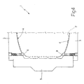
Figure 4 shows theFigure 1 mold housing a green tyre for curing. -
Number 1 inFigure 1 indicates as a whole a mold for curing a tyre 2 (shown by the dash line inFigure 4 ) . - Curing
mold 1 is in the form of a hollow cylinder, and comprises two oppositeparallel sidewalls 3 defining the base walls of curingmold 1 and having respective innerretaining surfaces 4 contacting a tyre 2 housed inside the mold.Curing mold 1 also comprises a number of (normally 8 or 9) lateral sectors 5 (only one shown inFigure 1 ) arranged successively to define the cylindrical lateral wall of the mold, and movable radially to and from the twosidewalls 3. -
Lateral sectors 5 are pushed radially towardssidewalls 3 by asystem 6 of inclined surfaces activated by a press (not shown). This solution is adopted in that it provides for grippinglateral sectors 5 againstsidewalls 3 with considerable force corresponding to a pressure of 25-30 bars necessary to counteract the pressure (normally at least 20 bars) generated insidemold 1 during the curing operation. - As shown in
Figures 2 and 3 , eachsidewall 3 comprises anannular seat 7 formed throughinner retaining surface 4, at the outer edge ofinner retaining surface 4. Eachseat 7 houses an annularmovable member 8, which is movable insideseat 7 between an extracted position (Figure 2 ), in whichmovable member 8 projects partly fromseat 7, and a withdrawn position (Figure 3 ), in whichmovable member 8 is housed completely insideseat 7.Movable member 8 is pushed out ofseat 7 into the extracted position with a given force by push means. In a preferred embodiment, the push means are elastic, and comprise a number of (e.g. twelve) springs 9 equally spaced alongmovable member 8. In an alternative embodiment not shown, the push means comprise one or more hydraulic, pneumatic, or electric actuators. - In a preferred embodiment, the outer wall of each
movable member 8 is shaped to blend seamlessly with innerretaining surface 4 whenmovable member 8 is in the withdrawn position, so that, in the withdrawn position, eachmovable member 8 in no way alters the normal contour ofinner retaining surface 4. - Each
spring 9 is housed inside a partly threaded throughhole 10 formed throughseat 7, and is compressed between an adjustingpin 11 screwed inside a threaded portion of throughhole 10, and a transmission body 12 (more specifically, a screw) screwed tomovable member 8. Screwing or unscrewing each adjustingpin 11 obviously adjusts the position of adjustingpin 11 along throughhole 10 and therefore the force exerted byspring 9 onmovable member 8. - Through
hole 10 has aconstriction 13 defining two stops, in turn defining the extracted and withdrawn positions ofmovable member 8. For example, to move from the withdrawn position to the extracted position,movable member 8 may travel a distance ranging between 1 and 10% of the width of tyre 2. For example, in the case of a car tyre,movable member 8 may travel approximately 5 mm. - As shown in
Figure 4 , when curingmold 1 is closed about a tyre 2, i.e. whenlateral sectors 5 are pushed ontosidewalls 3, the twomovable members 8 are pushed bysprings 9 into the extracted position, so that, at the mold parting line betweenlateral sectors 5 andsidewalls 3, tyre 2 is kept well away from the join betweenlateral sectors 5 andsidewalls 3, and so prevented from being pinched betweenlateral sectors 5 andsidewalls 3. - When curing
mold 1 is pressurized (e.g. to a pressure of about 20-22 bars), the expansion force on tyre 2 amply overcomes the force exerted bysprings 9 and so pushes the twomovable members 8 into the withdrawn position. It should be pointed out that the thrust exerted bysprings 9 on eachmovable member 8 must, obviously, be less than the expansion force exerted on tyre 2 when curingmold 1 is pressurized. - In various embodiments not shown, the form and/or number of
movable members 8 orsprings 9 may differ. - Curing
mold 1 as described above has numerous advantages, by being mechanically straightforward, cheap and easy to produce, and preventing the formation of flash. It is important to note that an existingcuring mold 1, with nomovable members 8, need not necessarily be scrapped, and can be equipped withmovable members 8 with only a few minor mechanical alterations.
Claims (11)
- A curing mold (1) for a tyre (2); the curing mold (1) is in the form of a hollow cylinder, and comprises:two parallel opposite sidewalls (3) defining the base walls of the curing mold (1) and having respective inner retaining surfaces (4) contacting a tyre (2) housed inside the curing mold (1); anda number of lateral sectors (5) arranged successively to define the cylindrical lateral wall of the curing mold (1), and movable radially to and from the two sidewalls (3);the curing mold (1) is characterized in that each sidewall (3) comprises:at least one seat (7) formed through the inner retaining surface (4), at the outer edge of the inner retaining surface (4);a movable member (8) housed inside the seat (7) and movable between an extracted position, in which the movable member (8) projects at least partly from the seat (7), and a withdrawn position, in which the movable member (8) is housed completely inside the seat (7); andpush means for pushing the movable member (8) out of the seat (7) into the extracted position with a given force.
- A curing mold (1) as claimed in Claim 1, wherein the seats (7) and the movable members (8) are annular.
- A curing mold (1) as claimed in Claim 1 or 2, wherein the outer wall of each movable member (8) is shaped to blend seamlessly with the inner retaining surface (4) when the movable member (8) is in the withdrawn position.
- A curing mold (1) as claimed in Claim 1, 2 or 3, wherein the extracted and withdrawn positions of each movable member (8) are determined by respective stops.
- A curing mold (1) as claimed in one of Claims 1 to 4, wherein the push means of each movable member (8) are elastic.
- A curing mold (1) as claimed in Claim 5, wherein the push means of each movable member (8) comprise a number of springs (9), each housed in a respective through hole (10) formed through the seat (7).
- A curing mold (1) as claimed in Claim 6, wherein each through hole (10) is partly threaded, and houses an adjusting pin (11); and each spring (9) is compressed between the adjusting pin (11) and the movable member (8).
- A curing mold (1) as claimed in Claim 6 or 7, wherein each through hole (10) has a constriction (13) to define two stops defining the extracted and withdrawn positions of the movable member (8).
- A curing mold (1) as claimed in Claim 8, wherein each movable member (8) is connected mechanically to each spring (9) by a transmission body (12) resting at one end on the spring (9), and screwed at the opposite end to the movable member (8).
- A curing mold (1) as claimed in one of Claims 1 to 9, wherein, to move from the withdrawn position to the extracted position, each movable member (8) travels a distance ranging between 1 and 10% of the width of the tyre (2).
- A curing mold (1) as claimed in one of Claims 1 to 10, wherein the thrust exerted by the push means on each movable member (8) is less than the expansion force acting on a tyre (2) housed inside the curing mold (1) when the curing mold (1) is pressurized.
Applications Claiming Priority (2)
| Application Number | Priority Date | Filing Date | Title |
|---|---|---|---|
| IT000532A ITTO20060532A1 (en) | 2006-07-19 | 2006-07-19 | VULCANIZATION MOLD FOR A TIRE |
| PCT/EP2007/057479 WO2008009724A1 (en) | 2006-07-19 | 2007-07-19 | Tyre curing mold |
Publications (2)
| Publication Number | Publication Date |
|---|---|
| EP2040911A1 EP2040911A1 (en) | 2009-04-01 |
| EP2040911B1 true EP2040911B1 (en) | 2010-09-29 |
Family
ID=38566188
Family Applications (1)
| Application Number | Title | Priority Date | Filing Date |
|---|---|---|---|
| EP07787736A Expired - Fee Related EP2040911B1 (en) | 2006-07-19 | 2007-07-19 | Tyre curing mold |
Country Status (6)
| Country | Link |
|---|---|
| US (1) | US7959424B2 (en) |
| EP (1) | EP2040911B1 (en) |
| DE (1) | DE602007009532D1 (en) |
| ES (1) | ES2350867T3 (en) |
| IT (1) | ITTO20060532A1 (en) |
| WO (1) | WO2008009724A1 (en) |
Cited By (1)
| Publication number | Priority date | Publication date | Assignee | Title |
|---|---|---|---|---|
| WO2015086580A1 (en) | 2013-12-10 | 2015-06-18 | Compagnie Generale Des Etablissements Michelin | Mould with sectors for a tyre including insulating supporting plates, and associated moulding method |
Families Citing this family (4)
| Publication number | Priority date | Publication date | Assignee | Title |
|---|---|---|---|---|
| US8075294B2 (en) | 2008-12-19 | 2011-12-13 | The Goodyear Tire & Rubber Company | Tire mold and tire with internal grooves in shoulder area |
| FR3014009B1 (en) | 2013-12-04 | 2016-11-04 | Michelin & Cie | PNEUMATIC SECTOR MOLD AND METHOD FOR MOLDING THE SAME |
| WO2020250069A1 (en) * | 2019-06-13 | 2020-12-17 | Pirelli Tyre S.P.A. | Insert for a mould for vulcanising tyres for vehicle wheels, method for producing said insert and method for producing a tyre |
| JP7577616B2 (en) | 2021-06-22 | 2024-11-05 | 株式会社ブリヂストン | Tire molding mold and tire manufacturing method |
Family Cites Families (10)
| Publication number | Priority date | Publication date | Assignee | Title |
|---|---|---|---|---|
| US3096541A (en) * | 1958-09-11 | 1963-07-09 | Goodyear Tire & Rubber | Apparatus for molding a valve receiving aperture in a tire |
| DE2502185C3 (en) * | 1975-01-21 | 1982-02-04 | Continental Gummi-Werke Ag, 3000 Hannover | Vulcanizing mold for pneumatic vehicle tires |
| US4655699A (en) * | 1984-03-07 | 1987-04-07 | The Uniroyal Goodrich Tire Company | Reduced flash molding apparatus |
| US4740145A (en) | 1987-07-15 | 1988-04-26 | The Firestone Tire & Rubber Company | Flash-free vented tire mold |
| FR2678862B1 (en) | 1991-07-10 | 1993-10-08 | Michelin & Cie | TIRE MOLD AND TIRE MOLDING METHOD USING SUCH A MOLD. |
| JP2955202B2 (en) * | 1995-02-13 | 1999-10-04 | 住友ゴム工業株式会社 | Pneumatic tire |
| JP2003071843A (en) * | 2001-09-04 | 2003-03-12 | Toyo Tire & Rubber Co Ltd | Mold for tire vulcanization molding |
| US20040018262A1 (en) * | 2002-07-24 | 2004-01-29 | Reep David M. | Segmented tire mold to reduce flash |
| EP1749632B1 (en) | 2004-05-27 | 2010-10-20 | Bridgestone Corporation | Tire vulcanizing mold |
| JP4506451B2 (en) * | 2004-12-17 | 2010-07-21 | 横浜ゴム株式会社 | Tire molding die and plug for tire molding die |
-
2006
- 2006-07-19 IT IT000532A patent/ITTO20060532A1/en unknown
-
2007
- 2007-07-19 WO PCT/EP2007/057479 patent/WO2008009724A1/en not_active Ceased
- 2007-07-19 ES ES07787736T patent/ES2350867T3/en active Active
- 2007-07-19 EP EP07787736A patent/EP2040911B1/en not_active Expired - Fee Related
- 2007-07-19 DE DE602007009532T patent/DE602007009532D1/en active Active
- 2007-07-19 US US12/309,353 patent/US7959424B2/en not_active Expired - Fee Related
Cited By (1)
| Publication number | Priority date | Publication date | Assignee | Title |
|---|---|---|---|---|
| WO2015086580A1 (en) | 2013-12-10 | 2015-06-18 | Compagnie Generale Des Etablissements Michelin | Mould with sectors for a tyre including insulating supporting plates, and associated moulding method |
Also Published As
| Publication number | Publication date |
|---|---|
| US7959424B2 (en) | 2011-06-14 |
| US20100009020A1 (en) | 2010-01-14 |
| WO2008009724A1 (en) | 2008-01-24 |
| DE602007009532D1 (en) | 2010-11-11 |
| ES2350867T3 (en) | 2011-01-27 |
| EP2040911A1 (en) | 2009-04-01 |
| ITTO20060532A1 (en) | 2008-01-20 |
Similar Documents
| Publication | Publication Date | Title |
|---|---|---|
| US7959424B2 (en) | Tyre curing mold | |
| JP3902248B2 (en) | Tire mold and molding method | |
| EP2173532B1 (en) | Air venting valve of vulcanising mould and method for removing air from a vulcanising mould | |
| US9522509B2 (en) | Tire mold vent | |
| KR102523548B1 (en) | Valve inserts and vent valves | |
| EP3099476B1 (en) | Tyre mould with a plate for moulding information on a sidewall | |
| KR20070104831A (en) | Tire molds for tire tread forming and pneumatic tires molded by the molds | |
| EP4360847B1 (en) | Tire molding mold and tire manufacturing method | |
| JP2009160862A (en) | Tire vulcanization mold | |
| KR200460078Y1 (en) | Venting plug of tire vulcanization mold | |
| CN116787827B (en) | A tire mold with replaceable type blocks | |
| JP2005145024A (en) | Mold for molding tire | |
| EP4360845B1 (en) | Tire molding mold and tire manufacturing method | |
| EP4360844B1 (en) | Tire molding die and tire production method | |
| EP4090524B1 (en) | Venting valve and method of mounting valve stem of venting valve | |
| KR102118108B1 (en) | Checking device for tire mold | |
| US12583195B2 (en) | Mold for forming a tire and tire production method | |
| EP4090525B1 (en) | Venting valve and method of mounting valve stem of venting valve | |
| KR101914431B1 (en) | Tire mold having side-wall vent apparatus | |
| JP4788254B2 (en) | Tire vulcanization mold | |
| KR100992390B1 (en) | Vulcanizing Mold for Automotive Tire | |
| KR20150022603A (en) | Tire Mold With Arrange Method |
Legal Events
| Date | Code | Title | Description |
|---|---|---|---|
| PUAI | Public reference made under article 153(3) epc to a published international application that has entered the european phase |
Free format text: ORIGINAL CODE: 0009012 |
|
| 17P | Request for examination filed |
Effective date: 20090131 |
|
| AK | Designated contracting states |
Kind code of ref document: A1 Designated state(s): AT BE BG CH CY CZ DE DK EE ES FI FR GB GR HU IE IS IT LI LT LU LV MC MT NL PL PT RO SE SI SK TR |
|
| AX | Request for extension of the european patent |
Extension state: AL BA HR MK RS |
|
| RBV | Designated contracting states (corrected) |
Designated state(s): DE ES FR GB |
|
| GRAP | Despatch of communication of intention to grant a patent |
Free format text: ORIGINAL CODE: EPIDOSNIGR1 |
|
| GRAS | Grant fee paid |
Free format text: ORIGINAL CODE: EPIDOSNIGR3 |
|
| GRAA | (expected) grant |
Free format text: ORIGINAL CODE: 0009210 |
|
| AK | Designated contracting states |
Kind code of ref document: B1 Designated state(s): DE ES FR GB |
|
| REG | Reference to a national code |
Ref country code: GB Ref legal event code: FG4D |
|
| REF | Corresponds to: |
Ref document number: 602007009532 Country of ref document: DE Date of ref document: 20101111 Kind code of ref document: P |
|
| REG | Reference to a national code |
Ref country code: ES Ref legal event code: FG2A Effective date: 20110117 |
|
| PLBE | No opposition filed within time limit |
Free format text: ORIGINAL CODE: 0009261 |
|
| STAA | Information on the status of an ep patent application or granted ep patent |
Free format text: STATUS: NO OPPOSITION FILED WITHIN TIME LIMIT |
|
| REG | Reference to a national code |
Ref country code: DE Ref legal event code: R097 Ref document number: 602007009532 Country of ref document: DE Effective date: 20110630 |
|
| GBPC | Gb: european patent ceased through non-payment of renewal fee |
Effective date: 20110719 |
|
| REG | Reference to a national code |
Ref country code: FR Ref legal event code: ST Effective date: 20120330 |
|
| PG25 | Lapsed in a contracting state [announced via postgrant information from national office to epo] |
Ref country code: DE Free format text: LAPSE BECAUSE OF NON-PAYMENT OF DUE FEES Effective date: 20120201 Ref country code: FR Free format text: LAPSE BECAUSE OF NON-PAYMENT OF DUE FEES Effective date: 20110801 |
|
| REG | Reference to a national code |
Ref country code: DE Ref legal event code: R119 Ref document number: 602007009532 Country of ref document: DE Effective date: 20120201 |
|
| PG25 | Lapsed in a contracting state [announced via postgrant information from national office to epo] |
Ref country code: GB Free format text: LAPSE BECAUSE OF NON-PAYMENT OF DUE FEES Effective date: 20110719 |
|
| REG | Reference to a national code |
Ref country code: ES Ref legal event code: FD2A Effective date: 20121122 |
|
| PG25 | Lapsed in a contracting state [announced via postgrant information from national office to epo] |
Ref country code: ES Free format text: LAPSE BECAUSE OF NON-PAYMENT OF DUE FEES Effective date: 20110720 |