EP2040886B1 - Cleaning tool system comprising a quick-release handle - Google Patents
Cleaning tool system comprising a quick-release handle Download PDFInfo
- Publication number
- EP2040886B1 EP2040886B1 EP07805083.8A EP07805083A EP2040886B1 EP 2040886 B1 EP2040886 B1 EP 2040886B1 EP 07805083 A EP07805083 A EP 07805083A EP 2040886 B1 EP2040886 B1 EP 2040886B1
- Authority
- EP
- European Patent Office
- Prior art keywords
- handle
- socket mount
- quick
- head
- shaft
- Prior art date
- Legal status (The legal status is an assumption and is not a legal conclusion. Google has not performed a legal analysis and makes no representation as to the accuracy of the status listed.)
- Ceased
Links
- 238000004140 cleaning Methods 0.000 title claims description 32
- 230000008878 coupling Effects 0.000 claims description 58
- 238000010168 coupling process Methods 0.000 claims description 58
- 238000005859 coupling reaction Methods 0.000 claims description 58
- 239000000758 substrate Substances 0.000 claims description 45
- 230000014759 maintenance of location Effects 0.000 claims description 15
- 244000007853 Sarothamnus scoparius Species 0.000 claims description 12
- 230000007935 neutral effect Effects 0.000 claims description 6
- 230000000994 depressogenic effect Effects 0.000 claims description 3
- 230000002093 peripheral effect Effects 0.000 claims description 3
- 235000010495 Sarothamnus scoparius Nutrition 0.000 description 11
- 238000013461 design Methods 0.000 description 7
- 230000007246 mechanism Effects 0.000 description 7
- 239000000463 material Substances 0.000 description 6
- 238000012423 maintenance Methods 0.000 description 4
- 206010020649 Hyperkeratosis Diseases 0.000 description 3
- 239000000428 dust Substances 0.000 description 3
- 238000003780 insertion Methods 0.000 description 3
- 230000037431 insertion Effects 0.000 description 3
- 229910052751 metal Inorganic materials 0.000 description 3
- 239000002184 metal Substances 0.000 description 3
- 239000003973 paint Substances 0.000 description 3
- 229920003023 plastic Polymers 0.000 description 3
- 239000004033 plastic Substances 0.000 description 3
- 230000000881 depressing effect Effects 0.000 description 2
- 125000006850 spacer group Chemical group 0.000 description 2
- 239000000126 substance Substances 0.000 description 2
- 241000251468 Actinopterygii Species 0.000 description 1
- 229920000122 acrylonitrile butadiene styrene Polymers 0.000 description 1
- 229910052782 aluminium Inorganic materials 0.000 description 1
- XAGFODPZIPBFFR-UHFFFAOYSA-N aluminium Chemical compound [Al] XAGFODPZIPBFFR-UHFFFAOYSA-N 0.000 description 1
- 238000005452 bending Methods 0.000 description 1
- 230000008901 benefit Effects 0.000 description 1
- 230000008859 change Effects 0.000 description 1
- 239000003086 colorant Substances 0.000 description 1
- 239000002131 composite material Substances 0.000 description 1
- 230000007423 decrease Effects 0.000 description 1
- 239000000835 fiber Substances 0.000 description 1
- 239000012530 fluid Substances 0.000 description 1
- 230000006870 function Effects 0.000 description 1
- 238000012986 modification Methods 0.000 description 1
- 230000004048 modification Effects 0.000 description 1
- 238000012545 processing Methods 0.000 description 1
- 230000002035 prolonged effect Effects 0.000 description 1
- 238000004064 recycling Methods 0.000 description 1
- 230000009467 reduction Effects 0.000 description 1
- 230000000717 retained effect Effects 0.000 description 1
- 239000005060 rubber Substances 0.000 description 1
- 239000007787 solid Substances 0.000 description 1
- 229910001220 stainless steel Inorganic materials 0.000 description 1
- 239000010935 stainless steel Substances 0.000 description 1
- 239000012209 synthetic fiber Substances 0.000 description 1
- 229920002994 synthetic fiber Polymers 0.000 description 1
- 239000002023 wood Substances 0.000 description 1
Images



Classifications
-
- B—PERFORMING OPERATIONS; TRANSPORTING
- B25—HAND TOOLS; PORTABLE POWER-DRIVEN TOOLS; MANIPULATORS
- B25G—HANDLES FOR HAND IMPLEMENTS
- B25G3/00—Attaching handles to the implements
- B25G3/02—Socket, tang, or like fixings
- B25G3/12—Locking and securing devices
- B25G3/28—Locking and securing devices comprising wedges, keys, or like expanding means
-
- B—PERFORMING OPERATIONS; TRANSPORTING
- B25—HAND TOOLS; PORTABLE POWER-DRIVEN TOOLS; MANIPULATORS
- B25G—HANDLES FOR HAND IMPLEMENTS
- B25G3/00—Attaching handles to the implements
- B25G3/02—Socket, tang, or like fixings
- B25G3/12—Locking and securing devices
- B25G3/32—Locking and securing devices in association with, or including, tang, bolt, or other member passing axially through whole length of handle
-
- Y—GENERAL TAGGING OF NEW TECHNOLOGICAL DEVELOPMENTS; GENERAL TAGGING OF CROSS-SECTIONAL TECHNOLOGIES SPANNING OVER SEVERAL SECTIONS OF THE IPC; TECHNICAL SUBJECTS COVERED BY FORMER USPC CROSS-REFERENCE ART COLLECTIONS [XRACs] AND DIGESTS
- Y10—TECHNICAL SUBJECTS COVERED BY FORMER USPC
- Y10T—TECHNICAL SUBJECTS COVERED BY FORMER US CLASSIFICATION
- Y10T403/00—Joints and connections
- Y10T403/59—Manually releaseable latch type
- Y10T403/591—Manually releaseable latch type having operating mechanism
- Y10T403/592—Ball detent
-
- Y—GENERAL TAGGING OF NEW TECHNOLOGICAL DEVELOPMENTS; GENERAL TAGGING OF CROSS-SECTIONAL TECHNOLOGIES SPANNING OVER SEVERAL SECTIONS OF THE IPC; TECHNICAL SUBJECTS COVERED BY FORMER USPC CROSS-REFERENCE ART COLLECTIONS [XRACs] AND DIGESTS
- Y10—TECHNICAL SUBJECTS COVERED BY FORMER USPC
- Y10T—TECHNICAL SUBJECTS COVERED BY FORMER US CLASSIFICATION
- Y10T403/00—Joints and connections
- Y10T403/59—Manually releaseable latch type
- Y10T403/591—Manually releaseable latch type having operating mechanism
- Y10T403/593—Remotely actuated
Definitions
- the working head attached to such handles will wear out or may otherwise be designed to be replaced.
- the heads are designed to be used a discreet number of times before the head must be cleaned or replaced.
- the handles are commonly attached to the working head with rivets, bolts, screws, and the like. Removing and replacing the working head can often be a time consuming task, may require tools that the user does not have readily available, and/or may be beyond the technical capabilities of the user.
- the handle In the case of many wet mops, dry dust mops, and brooms, the handle is often attached to the working head with a threaded tip at the end of the handle that mates with a threaded socket.
- a threaded tip at the end of the handle that mates with a threaded socket.
- connection and disconnection of such a handle is simple, it can be cumbersome and frustrating to the user, especially when the handle loosens from the head during use.
- Some wet string or sponge mops utilize various brackets, clamps, screws, support bars, and the like, to hold a disposable mopping substrate at the working end of the handle.
- the replacement of the mopping substrate often can be difficult and commonly requires the user to handle, touch, or otherwise manipulate the dirty mopping substrate. be difficult and commonly requires the user to handle, touch, or otherwise manipulate the dirty mopping substrate.
- a cleaning tool system with the features of the preamble to claim 1 is disclosed in US2004/187243A1 .
- fasteners means devices that fasten, join, connect, secure, hold, or clamp components together.
- Fasteners include, but are not limited to, screws, nuts and bolts, rivets, snap-fits, tacks, nails, loop fasteners, and interlocking male/female connectors, such as fishhook connectors, a fish hook connector includes a male portion with a protrusion on its circumference. Inserting the male portion into the female portion substantially permanently locks the two portions together.
- Couple includes, but is not limited to, joining, connecting, fastening, linking, or associating two things integrally or interstitially together.
- the term “configure(s)”, “configured” or “configuration(s)” means to design, arrange, set up, or shape with a view to specific applications or uses. For example: a military vehicle that was configured for rough terrain; configured the computer by setting the system's parameters.
- operable means being in a configuration such that use or operation is possible.
- operably connect(s) or “operably connected” refers to the relation of elements being so configured that a use or an operation is possible through their cooperation. For example: the machine is operable; the wheel is operably connected to the axle.
- Hinges refers to a jointed or flexible device that connects and permits pivoting or turning of a part to a stationary component.
- Hinges include, but are not limited to, metal pivotable connectors, such as those used to fasten a door to frame, and living hinges.
- Living hinges may be constructed from plastic and formed integrally between two members. A living hinge permits pivotable movement of one member in relation to another connected member.
- the term “substantially” refers to something which is done to a great extent or degree; for example, “substantially covered” means that a thing is at least 95% covered.
- alignment refers to the spatial property possessed by an arrangement or position of things in a straight line or in parallel lines.
- orientation or “position” used interchangeably herein refer to the spatial property of a place where or way in which something is situated; for example, “the position of the hands on the clock.”
- a handle that can work with a variety of working heads. It is also desired that such a handle be capable of quickly changing between various working heads and have a quick-release that allows such a change without the user having to come in close contact with the working head. It is also desired that the handle be designed to prevent calluses and blisters caused by the end of traditional handles during prolonged or repeated use.
- the present invention is directed to a cleaning tool system with a quick-release handle adapted for use with a cleaning tool working head configured to receive a handle.
- the quick-release handle includes a hollow elongated shaft with a quick-release coupling assembly on one end of the shaft and a button actuator on the opposite end of the shaft.
- the coupling assembly is configured to releaseably couple the handle to a socket mount.
- the button actuator is operably connected to the quick-release coupling assembly such that when the button actuator is depressed, the coupling assembly is disengaged from the socket mount.
- the button acuator is additionally recessed within the end of the shaft, and the handle includes an ergonomic, freely-rotating knob.
- the handle may additionally include a coupler shroud.
- the socket mounts may include a retention stop that engages the quick-release coupling assembly.
- the socket mounts may be threaded.
- the socket mount may include a spring that is compressed when the quick-release coupling assembly of a handle is inserted into the socket mount, the spring being biased to push the coupling assembly from the socket mount.
- the handle is a part of a cleaning tool system that includes a working head coupled to the socket mount.
- working heads include dry mop heads, wet mop heads, brooms and squeegees.
- the individual working heads may further include a head coupler that connects the working head to the socket mount and allows the handle to move up and down and from side to side relative to the working head.
- the socket mounts of such working heads may be configured to cooperatively engage a coupler shroud present on the quick-release handle.
- An embodiment of the present invention is also directed to a cleaning system including a quick-release handle and a plurality of working heads, each working head including a socket mount configured to cooperate with the quick release handle.
- the plurality of working heads may include a plurality of mop heads of various widths.
- the system may include a continuous web of cleaning substrate to be used with the plurality of mop heads, the continuous web having lines of weakness at regular intervals such that various widths of cleaning substrate are removable via the lines of weakness.
- a system may additionally include a container in which the continuous web of cleaning substrate may be contained and from which the substrate may be dispensed. Additionally, such a container may include a separator that assists in separating individual cleaning substrates from the continuous web of cleaning substrate.
- the quick-release handle 10 of the present invention includes an elongated shaft 12 having two opposite ends; a proximal end 16 and a distal end 18.
- the proximal end 16 is proximate to the working head to which the handle 10 is to be attached.
- the distal end 18 is distal to the proximal end 16 and proximate to the user.
- the proximal end 16 includes the quick-release coupling assembly 20 that will cooperate with and couple the handle 10 to a working head.
- the proximal end 16 is also considered as the Generally, the distal end 18 will have a grip 41 by which the user may grasp the handle 10.
- the distal end 18 is also considered the grip end of the handle 10 and the terms “distal end” and “grip end” may be used interchangeably. Additionally, the distal end 18 accommodates the button actuator 45 which the user depresses to release the coupling assembly 20 from any working head that may be coupled with the proximal end 16 of the handle 10. Thus, the user can release a working head from the handle 10 by manipulating the distal end 18 rather than repositioning the handle, bending over, or going anywhere near the potentially dirty proximal end 16 of the tool.
- the elongated shaft 12 is shown in FIG. 1 as generally cylindrical in shape, having a circular cross-section, as is common for most commonly available long tool handles. As such, the elongated shaft 12 has a single peripheral surface 14.
- the cross-sectional shape of the elongated shaft 12 may be elliptical, polygonal, or any other symmetrical or asymmetrical shape. Any such alternative cross-sectional shape may provide the elongated shaft 12 with additional peripheral surfaces 14.
- the elongated shaft 12 have a length of about 36 inches (0.9m) to about 72 inches (1.8m).
- the elongated shaft will preferably be about 5 feet (1.5m) in length, similar to the length of commonly available tool handles.
- the elongated shaft 12 should have an outside diameter suitable for the intended tool working heads and that is comfortable for use by range of user hand sizes. Typically, the outside diameter will be in the range of about 0.5 inches (12.7mm) to about 1.5 inches (38.1 mm). Preferably, the outside diameter of the shaft 12 will be similar to that of commonly available handles, 0.75 inches (19.1 mm).
- the shaft 12 illustrated in FIG. 1 is generally uniform in its diameter from the proximal end 16 to the distal end 18. However, the shaft 12 may alternatively have a nonuniform diameter along its length and may have sections of uniform and nonuniform diameter along its length.
- the elongated shaft 12 is hollow to accommodate the push rod 31 and the other associated elements of the button actuator 45 and quick-release coupling assembly 20.
- the hollowed nature of the shaft 12 also decreases the weight of the handle 10 and the amount of material used in making the handle 10.
- the thickness of the hollow elongated shaft 12 is a function of the materials used to make the shaft 12, the inside diameter required to accommodate the elements to be accommodated within the shaft 12, and the strength and weight desired. One skilled in the art would see how such variables could be balanced to produce the desired shaft 12.
- the elongated shaft 12 may be made from any material that meets the needs of the various working heads with which such a handle 10 is expected to be used. For example, a stronger shaft 12 may be desired for commercial applications while a lighter shaft may be desired for home applications. Other considerations may include, but are not limited to, weight, durability, compatibility with chemicals and substances the handle may come in contact, appearance, ease of cleaning, colors available, disposability, and the like.
- the shaft 12 may be made of a metal, plastic, or wood. More particularly, the shaft 12 may be made of aluminum, stainless steel, ABS-plastic, or the like. Again, one skilled in the art would see how such variables could be balanced to produce the desired shaft 12.
- the quick-release coupling assembly 20 is positioned on the proximal end 16 of the handle 10 and is configured to be coupled with a working head.
- the coupling assembly 20 may utilize any releasable coupling mechanism, as are well known, to releaseably couple with a working head.
- a releasable coupling mechanism may utilize a detent ball assembly (as illustrated in FIGS. 2 , 3A and 3B ), a collet, a chuck, a clamping spring, a bayonet mount, a barbed fastener, a ribbed shank clip fastener, or other such mechanisms or any combination thereof.
- the mechanism of the coupling assembly 20 is actuated by the user pressing and releasing the button actuator 45 on the distal end 18 of the shaft 12.
- the button actuator 45 is operably connected with the coupling assembly 20 by the push rod 31 which extends along the length of the shaft 12, from the button actuator 45 to the coupling assembly 20.
- the button actuator 45 is the terminus of the push rod 31 on the distal end 18 of the handle 10.
- a stop collar 33 is fitted around and attached to push rod 31 by a pin 34.
- a spring 35 around the push rod 31 and compressed between the stop collar 33 and the end wall of the stepped tip 21 of the coupling assembly 20 keeps the push rod 31 biased toward the distal end 18.
- the coupling assembly 20 at the proximal end 16 of the shaft 16 includes a stepped tip 21 having a first end 711 inserted into the proximal end 16 of the shaft 12 and a second end 719 that extends from the end of the shaft 12 and into the socket mount 63 of a head mount 61 of a working head to which the handle 10 is to be coupled.
- the stepped tip 21 has an internal longitudinal channel 22 that extends the length of the stepped tip 21, from the first end 711 to the second end 719.
- the first section 712 of the stepped tip 21 near the first end 711 has a diameter slightly smaller than the inside diameter of the shaft 12 such that the stepped tip 21 may be snuggly fit into the proximal end 16 of the shaft 12.
- a lip section 714 of the stepped tip 21 seats the stepped tip 21 in the proximal end 16 of the shaft 12 and prevents the stepped tip 21 from being pushed further into the shaft 12.
- the push rod 31 extends into the longitudinal channel 22 of the stepped tip 21.
- a stop rod 23 extends from the proximal end of the push rod 31 and is attached to the end of the push rod 31.
- the stop rod 23 extends out of the longitudinal channel 22 at the second end 719 of the stepped tip 21 and is capped by a head portion 25.
- the head portion 25 has a conical portion 26 that extends around the stop rod 23 inside the longitudinal channel 22.
- the third section 718 of the stepped tip 21 additionally includes ports 29 that extend from the longitudinal channel 22 to the outer surface of the stepped tip 21.
- a single detent ball 27 is retained by each port 29 and against the stop rod 23 or the conical portion 26.
- the spring 35 between the stop collar 33 and the first end 711 of the stepped tip 21 biases the push rod 31 toward the distal end 18 of the shaft 12.
- the stop rod 23 attached to both the head portion 25 and the push rod 31 is subsequently pulled into contact with the second end 719 of the stepped tip 21.
- the head portion 25 is only pulled to the second end 719 and thus the spring 35 cannot push the push rod 31 further toward the distal end 18 or pull the stop rod further into the stepped tip 21.
- the coupling assembly 20 and push rod 31 are held in a neutral state by the spring 35.
- the head portion 25 is pulled to the second end 719 of the stepped tip 21 such that the conical portion 26 of the head 25 is pulled into the longitudinal channel 22.
- the conical portion 26 engages the detent balls 27 and pushes them into the ports 29 such that the detent balls partially extend outside of the exterior wall of the third section 718 of the stepped tip 21.
- FIG. 3B illustrates the release configuration of the handle 10 and coupling assembly 20.
- the button actuator 45 When the user depresses the button actuator 45 at the distal end 18, the push rod 31 and the stop collar 33 is pushed toward the proximal end 16 of the shaft 12, compressing the spring 35 between the stop collar 33 and the first end 711 of the stepped tip 21.
- the stop rod 23, including the head 25, is consequently pushed away from the second end 719 of the stepped tip 21.
- the detent balls 27 are allowed to fall back into the longitudinal channel 22 and against the stop rod 23.
- the spring 35 returns the handle 10 to the engaged, or neutral, configuration as illustrated in FIG. 3A .
- the particular working head should include a head mount 61 that includes a socket mount 63 into which the coupling assembly 20 may be inserted.
- a retention stop 65 within the socket mount 63 cooperatively engages with the coupling assembly 20 to securely couple the working head and the quick-release handle 10.
- Such a retention stop 65 may be anything within the socket mount 63 that cooperatively engages the detent balls 27 of the coupling assembly 20.
- the retention stop 65 may be a ring fixed within the socket mount 63 (as shown in FIGS. 3A and 3B ), recesses within the wall of the socket mount 63, holes in the socket mount 63 (as shown in FIG. 9 ), or another configuration which can engage the detent balls 27.
- the stepped tip 21 In operation, when the coupling assembly 20 is inserted into the socket mount 63, the stepped tip 21 would proceed from the mouth of the socket recess 67 toward the recess terminus 67.
- the detent ball 27 When the coupling assembly 20 is in the engaged (neutral) configuration, the detent ball 27 are pushed out of the ports 29 by the conical portion 26 of the head 25, as discussed above.
- the inside diameter of the ring used as the retention stop 65 shown in FIGS. 3A and 3B is designed to be slightly larger than the outer diameter of the third portion 718 of the stepped tip 21.
- the detent balls 27 are forced into the ports 29 and push against the conical portion 26 and consequently push the head 25 from the second end 719.
- the detent balls 27 clear the retention stop 65 and are again forced out of the ports 29 by the conical portion 26.
- the detent balls 27 engage the retention stop 65 as illustrated in the engaged configuration shown in FIG. 3A .
- the socket mount 63 includes a socket recess 67 on the recess terminus side of the retention stop 65. Such a recess 67 allows enough room for the head 25 to extend from stepped tip 21 as necessary for the detent balls 27 to drop inside the stepped tip 21 during insertion of the coupling assembly 20 or release of the working head, as discussed above.
- coupling assembly 20 with the detent ball 27 mechanism described and illustrated in FIGS. 2 , 3A and 3B , is only one possible coupling assembly 20 that may be used in the handle 10 of the present invention.
- other coupling mechanisms are contemplated for the coupling assembly 20 to couple the handle 10 with a working head and operably connect to the button actuator 45 such that the working head is released from the handle 10 when the button actuator 45 is manipulated.
- the socket mount 63 may additionally be threaded from the mouth of the socket mount 63 to the retention stop 65. Such a socket mount 63 could then also accept a standard handle with a thread tip, if the user so desired.
- the second section 716 of the stepped tip 21 is designed to have an outside diameter slightly smaller than the inside diameter of the socket mount 63. This ensures that the coupling assembly 20 snuggly fits within the socket mount 63 such that the working head is securely and solidly held at the end of the handle 10. If the socket mount 63 is threaded, the second section 716 would need to have an outside diameter slightly smaller that the threads.
- a second spring could be included inside of the socket mount 63, attached to the recess terminus 69. Such a spring would be compressed upon insertion of the coupling assembly 20 into the socket mount 63. When the button actuator 45 was subsequently pressed to release the working head from the handle 10, such a spring would then bias the socket mount 63 off of the coupling assembly 20.
- Coupler shroud 71 Additional stability may be added to the connection of the head mount of the working head and the coupling assembly 20 by the inclusion of a coupler shroud 71 at the proximal end 16 of the shaft 12. As shown generally in FIGS. 6A, 6B , 7 and 8 , the coupler shroud 71 has portions that both protect the exposed coupling assembly 20 from damage and cooperate with the designs of the head mounts to securely couple the working head and handle 10.
- FIGS. 6A and 6B show an example of the coupler shroud 71 protecting the coupling assembly 20 on the proximal end 16 of a shaft 12.
- a wet mop head mount 361 is also shown, without the mop substrate attached to the head mount 361.
- Such a head mount 361 has shoulder portions 365 that cooperatively engage with the head shroud 71.
- the head mount 361 once the head mount 361 is engaged, the head mount 361, consequently the wet mop head including the head mount 361 is not able to rotate about the shaft axis.
- FIGS. 7 and 8 Another example of a coupler shroud 71 and cooperating head mount is shown in FIGS. 7 and 8 .
- the illustrated coupler shroud 71 and the head mount 161 are cooperatively designed such that coupler shroud 71 fits within the head mount 161 and the heat mount 161 fits within the coupler shroud 71.
- Such a cooperative design ensures a snug and solid coupling of the working head attached to the head mount 161 and the handle 10.
- Such a working head would be unable to rotate about the shaft axis.
- such a head mount 161 along with the coupler shroud 71 could help protect the coupling assembly 20 from damage and minimize the contact the coupling assembly 20 has with the outside environment during use.
- a head coupler 75 connects the head mount 161 to the body of a working head.
- the particular head coupler 75 shown in FIGS. 7 and 8 has a coupler bracket 79 that fits around a portion of the head mount 161, i.e., the cross-member 211 of the dry mop head 200 in FIG. 8 .
- a coupler spacer 77 cooperates with the coupler bracket 79 to hold the coupler bracket 79 against the cross-member 211.
- a pin 169 through the head mount 161, coupler bracket 19, and the coupler spacer 77 couples the head mount 161 and head coupler 75.
- the head coupler 75 allows the head coupler 75, the attached head mount 161, and the coupled quick-release handle 10 to rotate about the cross-member 211 and consequently allow the distal end 18 of the handle 10 to move vertically relative to the floor and the mop head 200. Additionally, the head coupler 75 is designed to interact with the head mount 161 such that the head mount 161 and coupled handle 10 may pivot on the pin 169 of the head coupler 75, such that the distal end 18 of the handle 10 may be pivoted from side-to-side, relative to the mop head 200.
- the distal end 18 is equipped with a knob 43 and may additionally feature a grip 41.
- the grip 41 has a slightly larger diameter than the shaft 12 and is preferably made of material, or is otherwise designed, to facilitate grasping of the shaft 12. Additionally, such a grip 41 should be designed to have the necessary durability required for the typical use of such handle 10.
- the grip 41 may be made of rubber, plastic, metal, or the like. Such materials may be given a texture through processing or through design by the addition of ridges, patterns, or divots to the surface of the grip 41 (as shown in FIGS. 4A and 4B ).
- the grip 41 as shown in FIGS. 1 , 4A, 4B and 5 , additionally has a knob 43 that also provides the user with more comfort than a traditional stick used with common brooms or mops.
- a traditional stick used with common brooms or mops Generally, such traditional sticks merely have the end rounded off and cause fatigue to the user's hand and often result in blisters or calluses in the palm of the hand after extended use. The small diameter of the end of such traditional sticks causes discomfort and is often difficult for the user to fully grasp.
- a knob 43 such as shown in FIGS. 4A, 4B and 5 , provides the user with a much larger diameter end to the handle 10 compared to traditional sticks.
- the larger diameter of the knob 43, relative to traditional sticks makes the knob 43 much easier to grasp.
- By increasing the surface area of the distal end surface 19 of the knob 43 the forces experienced by the user's hand are spread out over a greater surface area than can be achieved by a rounded end of a traditional stick. Such a better distribution of forces result in a reduction in the amount of fatigue the user experience in their hand.
- the knob 43 may be formed as a unitary part of the terminus of the grip 41 or it may be an additional part added to the distal end 18 of the shaft 12.
- the knob 43 shown in FIGS. 4A, 4B and 5 is only intended to be an exemplary shape for such a knob 43; the knob 43 may be any size and shape, symmetrical or asymmetrical, that allows the user to comfortably grasp and utilize the handle 10.
- the shape of the knob 43 is extended to the grip 41 of the distal end 18 of the handle10.
- This functional grab area 44 of the knob 43 allows a user to maintain a grip of the knob 43, when the user pushes the handle 10 away from their body. This is particularly useful in mopping when a user will regularly "cast out” a mop and then bring the handle 10 and mop back to themselves.
- the button actuator 45 is also present at the distal end 18 of the handle 10. As shown in FIGS. 4A and 5 , the button actuator 45 is incorporated into the knob 43 and is recessed within the distal end surface 19. As such, the user may grasp the knob 43 during use without unintentionally depressing the button actuator 45 and accidentally releasing the working head.
- the button actuator 45 shown in FIGS. 4A, 4B, and 5 is merely the terminus of the push rod 31. However, the button actuator 45 may be a separate piece attached or otherwise operably connected to the push rod 31
- the knob 43 as shown in FIGS. 4A, 4B and 5 , has the added ability to freely rotate 360-degrees on the terminus of the distal end 18 of the shaft 12. Such a freely-rotating knob 43 reduces the rubbing and twisting that the user's hand experiences when using traditional sticks. By allowing the knob 43 to freely rotate, the user may maintain a grasp on the knob 43 during regular use of the tool and avoid the fatigue and blisters that often accompanied use of a traditional push broom, mop, or floor duster.
- the rotation of the knob 43 may be accomplished with by any type of mechanical bearings, as are well known, that allow the desired 360-degrees of free rotation.
- the rotation may be accomplished with sliding bearings or bushings, rolling-element bearings (such as ball bearings, roller bearings, taper roller bearings), fluid bearings, magnetic bearings, or the like.
- the rotation of the knob 43 is accomplished with a track of ball bearings 51 that are held in place by cooperative recesses in both the end of the grip 41 and in the knob 43.
- the ball bearings 51 allow the knob 43 to freely-rotate a full 360-degrees about the axis of the shaft 12, on the end of the grip 41.
- FIGS. 4A, 4B and 5 The assembly of the freely-rotating knob 43 is illustrated in FIGS. 4A, 4B and 5 .
- a shaft sleeve 53 is associated with the knob 43 such that the shaft sleeve 53 fits over the push rod 31 when the knob 43 and associated shaft sleeve 53 are inserted into shaft 12.
- a knob-connecting collar 55 inserted into the shaft 12 fits around the shaft collar 53.
- a set screw 57 is inserted from the exterior of the handle 10, through the grip 41, through the shaft 12, and into the knob-connecting collar 55. As such, the set screw 57, holds the knob-connecting collar 55 in place within the interior of the shaft 12.
- the set screw 57 is aligned with a notch 59 circumscribed on the exterior of the shaft sleeve 53. With the set screw 57 in place within the notch 59, the knob 43 is held firmly in place on the terminus of the handle 10 and against the ball bearings 51. As such the knob 43 may freely rotate 360-degrees upon the ball bearings 51, the shaft sleeve 53 is allowed to also freely rotate within the shaft 12, and the knob 43 is kept from being pulled from the end of the handle 10.
- the shaft sleeve 53 has an interior diameter that allows the push rod 31 to pass through the shaft sleeve 53 such that knob 43 and shaft sleeve 53 may freely rotate about push rod 31.
- the button actuator 45 is recessed within the distal end surface 19. When in use, the knob 43 freely rotates about the button actuator 45 and push rod 31 without the risk of the user unintentionally depressing the button actuator 45 or the nonrotating button actuator 45 rubbing on the palm of the user's hand.
- the quick-release handle 10 could be a part of an interchangeable system of working heads including socket mounts that accommodate the quick-release coupling assembly 20. The user would then be able to use a myriad of working heads with the same handle 10 and thus reduce the clutter associated with each tool having its own handle.
- the system may include a dry mop head 200 such as shown in FIG. 8 and a wet mop head using the wet mop head mount 361, such as shown in FIGS. 6A and 6B .
- the system may include a variety of dry mop heads 200, such as shown in FIG. 8 , each having a different width for the various cleaning tasks to be performed.
- FIG. 9 Another wet mop head is shown in FIG. 9 and utilizes a simpler socket mount 463 than used in the previous examples.
- the socket mount 463 may attach a wet mop substrate 410 by the use of a substrate attachment collar 467. As shown in FIG. 9 , the socket mount 463 may have holes inside the socket to act as a retention stop 65. The detent balls 27 of the coupling assembly 20 could then engage such holes to secure the wet mop head to the shaft 12 of the handle 10.
- Non-limiting examples of other possible working heads may include a whisk broom (see FIG. 10A ), a squeegee (see FIG. 10B ), a push broom (see FIG. 10C ), dusters, and the like.
- Other non-cleaning related working heads that could be used include paint roller attachments, light bulb changers, tree trimmer saws, and the like.
- any working head/tool that utilizes a long handle could be modified to take advantage of the quick-release handle 10 of the present invention.
- the interchangeable system may also include cleaning substrates for use with mop heads that use disposable substrates.
- cleaning substrates are widely available and well understood.
- substrates may be woven, nonwoven, laminates, composites, or combinations thereof, and may be made from natural fibers, synthetic fibers, or combinations thereof.
- Such disposable cleaning substrates are most commonly provided in the size, width and design that is appropriate for the particular mop head that it is to be used. As part of an interchangeable system of working heads that includes a variety of head widths, providing a multiple substrates may be cumbersome and unwieldy.
- One solution is the use of a continuous web of selectable-size cleaning substrate as a part of the system.
- the continuous web of selectable-size substrate 85 may have lines of weakness 87 at regular intervals along the length of the web 85.
- Such lines of weakness 87 may be perforations, scoring, areas of weakened material, or other similar character that allows a portion of the cleaning substrate to be removed from the continuous web of substrate 85.
- the regular interval between the lines of weakness 87 would be an interval that would balance the needs of various widths of working heads.
- the system of the present invention may include floor mops having head widths of 12 inches (305mm), 18 inches (457mm), 24 inches (610mm), 36 inches (914mm), and 48 inches (1.2m).
- a selectable-size substrate 85 would preferably have lines of weakness 87 at 6-inch (152mm) intervals. The user would then be able to easily tear off any appropriate length of substrate 85 for the particular width head that they were using.
- Such disposable cleaning substrates may be a single flat sheet as shown in FIG. 11 , a folded or two-ply sheet as shown in FIG. 12 , a tubular substrate, or other formats that could be provided as a continuous web and as necessary for the various working heads of the system. As shown in FIG. 12 , such substrates may additionally include substrate fasteners 93 that may interact with the particular working heads to attach the substrate to those working heads.
- the selectable-size substrate shown in FIG. 11 is provided in a roll format 89.
- the roll 89 could be mounted in a roll product dispenser, as are commonly available and widely understood. Such a dispenser could be available on the wall, on a cart, or wherever would be most convenient for the user of the system.
- the selectable-size substrate 85 may be provided to the user in a container 98, such as shown in FIG. 12 .
- the substrate 85 could be stored and dispensed from the container 98 through a dispensing opening 97 in the container 98.
- the substrate 85 may be available in the container 98 in any format that is desired. It may be a roll 89, as in FIG. 11 , merely piled in the container 98, or may be festooned within the container 98.
- the container 98 may have a separator 99 that the user could use to more easily separate the cleaning substrate along the lines of weakness 87.
- Such containers 98 may also include indicia that would help the user identify the amount or type of substrate contained, instructions on proper use, disposal instructions, or other messages that are desired to be conveyed to the user.
- indicia may be any word(s), numeral(s), line(s), symbol(s), picture(s), color(s) and/or combination(s) thereof, that convey the desired message.
- the container 98 may have additional features such as viewing slots such the user can see the amount of remaining substrate, mounting brackets for mounting the container 98 on a support surface, disposal / recycling features, or other such characteristics that enhance the system and make it easier to use.
Landscapes
- Engineering & Computer Science (AREA)
- Mechanical Engineering (AREA)
- Cleaning Implements For Floors, Carpets, Furniture, Walls, And The Like (AREA)
Description
- Long shaft handles have been used as a part of various tools for as long as tools have been used. Such handles allow maintenance personnel to clean floors while in a standing position when the handle is attached to a mop head, or allows a painter to paint a ceiling when the handle is attached to a paint roller. Generally, each tool working head is fitted with its own handle such that a person with a collection of various tools will often have a closet, cabinet, wall rack or garden shed cluttered with a collection of such handles, each attached to its own tool working head. For example, building maintenance personnel may require a collection of wet mops, dry dust mops of various widths, squeegees, brooms, and other such items, each with its own handle. Such a collection of tools can create a cluttered maintenance closet or may be cumbersomely attached to a maintenance cart.
- Often the working head attached to such handles will wear out or may otherwise be designed to be replaced. In the case of wet mops and dry dust mops, the heads are designed to be used a discreet number of times before the head must be cleaned or replaced. The handles are commonly attached to the working head with rivets, bolts, screws, and the like. Removing and replacing the working head can often be a time consuming task, may require tools that the user does not have readily available, and/or may be beyond the technical capabilities of the user.
- In the case of many wet mops, dry dust mops, and brooms, the handle is often attached to the working head with a threaded tip at the end of the handle that mates with a threaded socket. However, while the connection and disconnection of such a handle is simple, it can be cumbersome and frustrating to the user, especially when the handle loosens from the head during use.
- Some wet string or sponge mops utilize various brackets, clamps, screws, support bars, and the like, to hold a disposable mopping substrate at the working end of the handle. However, the replacement of the mopping substrate often can be difficult and commonly requires the user to handle, touch, or otherwise manipulate the dirty mopping substrate.
be difficult and commonly requires the user to handle, touch, or otherwise manipulate the dirty mopping substrate. - Others have attempted to solve the inconvenience of switching working heads by employing quick connect and release mechanisms to join various types of working heads to handles. Such quick connects often use a male connector that is mated with a female fitting. Commonly, the male connector will include opposing end portions that will snap into matching slots or holes in the female fitting such that the end portions are pinched together to subsequently release the male connector from the female fitting. However, the problem with this, or other such common quick connect and release designs, is that the user has to manipulate the tool where the working head is connected to the handle. Often this is the "dirty" end of the tool (e.g., close to the used mop head) and minimally requires that the user bend over or reposition the tool to be able to so manipulate the quick release.
- Finally, another related problem associated with the regular use of long-handled tools such as mops, brooms, and the like, is related to wear and fatigue to the user's hands. During regular use of a mop, broom or other similar tool, the end of the tool regularly twists and rubs on the user's hand. If the user is not wearing gloves, such repeated use often leaves painful calluses or blisters on the palm of the user's hand.
- A cleaning tool system with the features of the preamble to claim 1 is disclosed in
US2004/187243A1 . - As used herein, the term "fasteners" means devices that fasten, join, connect, secure, hold, or clamp components together. Fasteners include, but are not limited to, screws, nuts and bolts, rivets, snap-fits, tacks, nails, loop fasteners, and interlocking male/female connectors, such as fishhook connectors, a fish hook connector includes a male portion with a protrusion on its circumference. Inserting the male portion into the female portion substantially permanently locks the two portions together.
- As used herein, the term "couple" includes, but is not limited to, joining, connecting, fastening, linking, or associating two things integrally or interstitially together.
- As used herein, the term "configure(s)", "configured" or "configuration(s)" means to design, arrange, set up, or shape with a view to specific applications or uses. For example: a military vehicle that was configured for rough terrain; configured the computer by setting the system's parameters.
- As used here, the term "operable" or "operably" means being in a configuration such that use or operation is possible. Similarly, "operably connect(s)" or "operably connected" refers to the relation of elements being so configured that a use or an operation is possible through their cooperation. For example: the machine is operable; the wheel is operably connected to the axle.
- As used herein, the term "hinge" refers to a jointed or flexible device that connects and permits pivoting or turning of a part to a stationary component. Hinges include, but are not limited to, metal pivotable connectors, such as those used to fasten a door to frame, and living hinges. Living hinges may be constructed from plastic and formed integrally between two members. A living hinge permits pivotable movement of one member in relation to another connected member.
- As used herein, the term "substantially" refers to something which is done to a great extent or degree; for example, "substantially covered" means that a thing is at least 95% covered.
- As used herein, the term "alignment" refers to the spatial property possessed by an arrangement or position of things in a straight line or in parallel lines.
- As user herein, the terms "orientation" or "position" used interchangeably herein refer to the spatial property of a place where or way in which something is situated; for example, "the position of the hands on the clock."
- These terms may be defined with additional language in the remaining portions of the specification.
- In light of the problems and issues discussed above, it is desired to have a handle that can work with a variety of working heads. It is also desired that such a handle be capable of quickly changing between various working heads and have a quick-release that allows such a change without the user having to come in close contact with the working head. It is also desired that the handle be designed to prevent calluses and blisters caused by the end of traditional handles during prolonged or repeated use.
- In accordance with one aspect of the present invention there is provided a cleaning tool system as set forth in claim 1.
- The present invention is directed to a cleaning tool system with a quick-release handle adapted for use with a cleaning tool working head configured to receive a handle. The quick-release handle includes a hollow elongated shaft with a quick-release coupling assembly on one end of the shaft and a button actuator on the opposite end of the shaft. The coupling assembly is configured to releaseably couple the handle to a socket mount. The button actuator is operably connected to the quick-release coupling assembly such that when the button actuator is depressed, the coupling assembly is disengaged from the socket mount. The button acuator is additionally recessed within the end of the shaft, and the handle includes an ergonomic, freely-rotating knob.
- In various embodiments of the present invention, the handle may additionally include a coupler shroud. In some embodiments, the socket mounts may include a retention stop that engages the quick-release coupling assembly. In some embodiments, the socket mounts may be threaded. Finally, the socket mount may include a spring that is compressed when the quick-release coupling assembly of a handle is inserted into the socket mount, the spring being biased to push the coupling assembly from the socket mount.
- The handle is a part of a cleaning tool system that includes a working head coupled to the socket mount. Such working heads include dry mop heads, wet mop heads, brooms and squeegees. The individual working heads may further include a head coupler that connects the working head to the socket mount and allows the handle to move up and down and from side to side relative to the working head. Additionally, the socket mounts of such working heads may be configured to cooperatively engage a coupler shroud present on the quick-release handle.
- An embodiment of the present invention is also directed to a cleaning system including a quick-release handle and a plurality of working heads, each working head including a socket mount configured to cooperate with the quick release handle. In various embodiments, the plurality of working heads may include a plurality of mop heads of various widths.
- In some embodiments, the system may include a continuous web of cleaning substrate to be used with the plurality of mop heads, the continuous web having lines of weakness at regular intervals such that various widths of cleaning substrate are removable via the lines of weakness. Such a system may additionally include a container in which the continuous web of cleaning substrate may be contained and from which the substrate may be dispensed. Additionally, such a container may include a separator that assists in separating individual cleaning substrates from the continuous web of cleaning substrate.
-
-
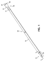
FIG. 1 is a perspective view of a quick-release handle of the present invention; -
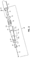
FIG. 2 is a partial perspective exploded view of a quick-release coupling assembly of the handle ofFIG. 1 ; -
FIG. 3A is a cross-sectional view of a quick-release coupling assembly of the handle ofFIG. 1 taken along line 3-3, shown in an engaged configuration with a generic socket mount (illustrated by phantom lines); -
FIG. 3B is a cross-sectional view of the quick-release coupling assembly of the handle ofFIG. 1 taken along line 3-3, shown in a release configuration in relation to the generic socket mount (illustrated by phantom lines); -
FIG. 4A is a partial perspective view of the distal end of the quick-release handle ofFIG. 1 showing a grip, a freely-rotating knob, and a button actuator; -
FIG. 4B is a partial perspective exploded view of the distal end of the quick-release handle ofFIG. 4A ; -
FIG. 5 is a cross-sectional view of the distal end of the quick-release handle ofFIG. 4A taken along the line 5-5; -
FIG. 6A is a partial perspective view of the proximal end of the quick-release handle, the proximal end including a coupler shroud and positioned to engage a head mount; -
FIG. 6B is a partial perspective view of the proximal end of the quick-release handle ofFIG. 6A showing the coupler shroud coupled to the head mount; -
FIG. 7 is a partial perspective view of the proximal end of the quick-release handle, the proximal end including a coupler shroud and positioned to coupled to a head mount, the head mount including a head coupler; -
FIG. 8 is a partial perspective view of the proximal end of the quick-release handle including a coupler shroud and coupled to a dry mop working head; -
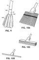
FIG. 9 is a partial perspective view of the proximal end of the quick-release handle coupled to a wet mop working head; -
FIG. 10A is a partial perspective view of the proximal end of the quick-release handle coupled to a whisk broom working head; -
FIG. 10B is a partial perspective view of the proximal end of the quick-release handle coupled to a squeegee working head; -
FIG. 10C is a partial perspective view of the proximal end of the quick-release handle coupled to a push broom working head; -
FIG. 11 is a perspective view of a continuous web of selectable-width cleaning substrate in a roll format; and -
FIG. 12 is a perspective view of a continuous web of selectable-width cleaning substrate and disposed within a container. - Reference will now be made in detail to one or more embodiments of the invention, examples of which are illustrated in the drawings. Each example and embodiment is provided by way of explanation of the invention, and is not meant as a limitation of the invention. For example, features illustrated or described as part of one embodiment may be used with another embodiment to yield still a further embodiment. It is intended that the invention include these and other modifications and variations as coming within the scope of the invention.
- Referring to
FIGS. 1 to 5 in general, the quick-release handle 10 of the present invention includes anelongated shaft 12 having two opposite ends; aproximal end 16 and adistal end 18. Theproximal end 16 is proximate to the working head to which thehandle 10 is to be attached. Thedistal end 18 is distal to theproximal end 16 and proximate to the user. Theproximal end 16 includes the quick-release coupling assembly 20 that will cooperate with and couple thehandle 10 to a working head. Theproximal end 16 is also considered as the Generally, thedistal end 18 will have agrip 41 by which the user may grasp thehandle 10. Thedistal end 18 is also considered the grip end of thehandle 10 and the terms "distal end" and "grip end" may be used interchangeably. Additionally, thedistal end 18 accommodates thebutton actuator 45 which the user depresses to release thecoupling assembly 20 from any working head that may be coupled with theproximal end 16 of thehandle 10. Thus, the user can release a working head from thehandle 10 by manipulating thedistal end 18 rather than repositioning the handle, bending over, or going anywhere near the potentially dirtyproximal end 16 of the tool. - The
elongated shaft 12 is shown inFIG. 1 as generally cylindrical in shape, having a circular cross-section, as is common for most commonly available long tool handles. As such, theelongated shaft 12 has a singleperipheral surface 14. However, other cross-sectional shapes are contemplated and are considered within the scope of the present invention. By way of non-limiting examples, the cross-sectional shape of theelongated shaft 12 may be elliptical, polygonal, or any other symmetrical or asymmetrical shape. Any such alternative cross-sectional shape may provide theelongated shaft 12 with additionalperipheral surfaces 14. - Generally, it is desired that the
elongated shaft 12 have a length of about 36 inches (0.9m) to about 72 inches (1.8m). For a quick-release handle 10 for use with cleaning tool working heads, the elongated shaft will preferably be about 5 feet (1.5m) in length, similar to the length of commonly available tool handles. Theelongated shaft 12 should have an outside diameter suitable for the intended tool working heads and that is comfortable for use by range of user hand sizes. Typically, the outside diameter will be in the range of about 0.5 inches (12.7mm) to about 1.5 inches (38.1 mm). Preferably, the outside diameter of theshaft 12 will be similar to that of commonly available handles, 0.75 inches (19.1 mm). Also, theshaft 12 illustrated inFIG. 1 is generally uniform in its diameter from theproximal end 16 to thedistal end 18. However, theshaft 12 may alternatively have a nonuniform diameter along its length and may have sections of uniform and nonuniform diameter along its length. - The
elongated shaft 12 is hollow to accommodate thepush rod 31 and the other associated elements of thebutton actuator 45 and quick-release coupling assembly 20. The hollowed nature of theshaft 12 also decreases the weight of thehandle 10 and the amount of material used in making thehandle 10. The thickness of the hollow elongatedshaft 12 is a function of the materials used to make theshaft 12, the inside diameter required to accommodate the elements to be accommodated within theshaft 12, and the strength and weight desired. One skilled in the art would see how such variables could be balanced to produce the desiredshaft 12. - The
elongated shaft 12 may be made from any material that meets the needs of the various working heads with which such ahandle 10 is expected to be used. For example, astronger shaft 12 may be desired for commercial applications while a lighter shaft may be desired for home applications. Other considerations may include, but are not limited to, weight, durability, compatibility with chemicals and substances the handle may come in contact, appearance, ease of cleaning, colors available, disposability, and the like. Typically, theshaft 12 may be made of a metal, plastic, or wood. More particularly, theshaft 12 may be made of aluminum, stainless steel, ABS-plastic, or the like. Again, one skilled in the art would see how such variables could be balanced to produce the desiredshaft 12. - Additionally, designs in which the
shaft 12 is telescoping, collapsible, and/or foldable are also considered to be within the scope of the present invention. - As discussed above, the quick-
release coupling assembly 20 is positioned on theproximal end 16 of thehandle 10 and is configured to be coupled with a working head. Thecoupling assembly 20 may utilize any releasable coupling mechanism, as are well known, to releaseably couple with a working head. By way of non-limiting examples, such a releasable coupling mechanism may utilize a detent ball assembly (as illustrated inFIGS. 2 ,3A and 3B ), a collet, a chuck, a clamping spring, a bayonet mount, a barbed fastener, a ribbed shank clip fastener, or other such mechanisms or any combination thereof. - The mechanism of the
coupling assembly 20 is actuated by the user pressing and releasing thebutton actuator 45 on thedistal end 18 of theshaft 12. Thebutton actuator 45 is operably connected with thecoupling assembly 20 by thepush rod 31 which extends along the length of theshaft 12, from thebutton actuator 45 to thecoupling assembly 20. As can be seen in the example illustrated inFIGS. 2 ,3A ,3B ,4A, 4B and 5 , thebutton actuator 45 is the terminus of thepush rod 31 on thedistal end 18 of thehandle 10. At the proximal end of thepush rod 31, astop collar 33 is fitted around and attached to pushrod 31 by apin 34. Aspring 35 around thepush rod 31 and compressed between thestop collar 33 and the end wall of the steppedtip 21 of thecoupling assembly 20 keeps thepush rod 31 biased toward thedistal end 18. - As shown in
FIGS. 2 ,3A, and 3B , thecoupling assembly 20 at theproximal end 16 of theshaft 16 includes a steppedtip 21 having afirst end 711 inserted into theproximal end 16 of theshaft 12 and asecond end 719 that extends from the end of theshaft 12 and into thesocket mount 63 of ahead mount 61 of a working head to which thehandle 10 is to be coupled. The steppedtip 21 has an internal longitudinal channel 22 that extends the length of the steppedtip 21, from thefirst end 711 to thesecond end 719. Thefirst section 712 of the steppedtip 21 near thefirst end 711 has a diameter slightly smaller than the inside diameter of theshaft 12 such that the steppedtip 21 may be snuggly fit into theproximal end 16 of theshaft 12. Alip section 714 of the steppedtip 21 seats the steppedtip 21 in theproximal end 16 of theshaft 12 and prevents the steppedtip 21 from being pushed further into theshaft 12. - As illustrated in
FIGS. 3A and 3B , once the steppedtip 21 is installed in theshaft 12, thepush rod 31 extends into the longitudinal channel 22 of the steppedtip 21. Astop rod 23 extends from the proximal end of thepush rod 31 and is attached to the end of thepush rod 31. Thestop rod 23 extends out of the longitudinal channel 22 at thesecond end 719 of the steppedtip 21 and is capped by ahead portion 25. Thehead portion 25 has aconical portion 26 that extends around thestop rod 23 inside the longitudinal channel 22. When thestop rod 23 is attached to both thepush rod 31 and thehead portion 25, thespring 31 that biases thepush rod 31 toward the distal end 18 (as discussed above) also pulls thehead portion 25 against thesecond end 719 of the steppedtip 21. - The
third section 718 of the steppedtip 21 additionally includesports 29 that extend from the longitudinal channel 22 to the outer surface of the steppedtip 21. Asingle detent ball 27 is retained by eachport 29 and against thestop rod 23 or theconical portion 26. - When the
handle 10 andcoupling assembly 20 are in the engaged configuration, such as shown inFIG. 3A , thespring 35 between thestop collar 33 and thefirst end 711 of the steppedtip 21 biases thepush rod 31 toward thedistal end 18 of theshaft 12. Thestop rod 23 attached to both thehead portion 25 and thepush rod 31 is subsequently pulled into contact with thesecond end 719 of the steppedtip 21. Thehead portion 25 is only pulled to thesecond end 719 and thus thespring 35 cannot push thepush rod 31 further toward thedistal end 18 or pull the stop rod further into the steppedtip 21. In such an engaged configuration, thecoupling assembly 20 and pushrod 31 are held in a neutral state by thespring 35. - As shown in
FIG. 3A , when thecoupling assembly 20 is in the engaged state, thehead portion 25 is pulled to thesecond end 719 of the steppedtip 21 such that theconical portion 26 of thehead 25 is pulled into the longitudinal channel 22. Theconical portion 26 engages thedetent balls 27 and pushes them into theports 29 such that the detent balls partially extend outside of the exterior wall of thethird section 718 of the steppedtip 21. -
FIG. 3B illustrates the release configuration of thehandle 10 andcoupling assembly 20. When the user depresses thebutton actuator 45 at thedistal end 18, thepush rod 31 and thestop collar 33 is pushed toward theproximal end 16 of theshaft 12, compressing thespring 35 between thestop collar 33 and thefirst end 711 of the steppedtip 21. Thestop rod 23, including thehead 25, is consequently pushed away from thesecond end 719 of the steppedtip 21. As theconical portion 26 of thehead 25 is pushed toward thesecond end 719, thedetent balls 27 are allowed to fall back into the longitudinal channel 22 and against thestop rod 23. When the user releases thebutton actuator 45, thespring 35 returns thehandle 10 to the engaged, or neutral, configuration as illustrated inFIG. 3A . - Various working heads could be used with this type of
handle 10 andcoupling assembly 20. To work with thecoupling assembly 20, the particular working head should include ahead mount 61 that includes asocket mount 63 into which thecoupling assembly 20 may be inserted. Aretention stop 65 within thesocket mount 63 cooperatively engages with thecoupling assembly 20 to securely couple the working head and the quick-release handle 10. Such aretention stop 65 may be anything within thesocket mount 63 that cooperatively engages thedetent balls 27 of thecoupling assembly 20. By way of non-limiting examples, theretention stop 65 may be a ring fixed within the socket mount 63 (as shown inFIGS. 3A and 3B ), recesses within the wall of thesocket mount 63, holes in the socket mount 63 (as shown inFIG. 9 ), or another configuration which can engage thedetent balls 27. - In operation, when the
coupling assembly 20 is inserted into thesocket mount 63, the steppedtip 21 would proceed from the mouth of thesocket recess 67 toward therecess terminus 67. When thecoupling assembly 20 is in the engaged (neutral) configuration, thedetent ball 27 are pushed out of theports 29 by theconical portion 26 of thehead 25, as discussed above. The inside diameter of the ring used as theretention stop 65 shown inFIGS. 3A and 3B is designed to be slightly larger than the outer diameter of thethird portion 718 of the steppedtip 21. Thus, as the steppedtip 21 is inserted into thesocket mount 63, thethird portion 718 snugly passes into theretention stop 65, but the protrudingdetent balls 27 will come into contact with theretention stop 65. As the user continues to apply insertion pressure to the steppedtip 21, thedetent balls 27 are forced into theports 29 and push against theconical portion 26 and consequently push thehead 25 from thesecond end 719. Once the steppedtip 21 is pushed farther into thesocket mount 63, thedetent balls 27 clear theretention stop 65 and are again forced out of theports 29 by theconical portion 26. Thedetent balls 27 engage theretention stop 65 as illustrated in the engaged configuration shown inFIG. 3A . - The
socket mount 63 includes asocket recess 67 on the recess terminus side of theretention stop 65. Such arecess 67 allows enough room for thehead 25 to extend from steppedtip 21 as necessary for thedetent balls 27 to drop inside the steppedtip 21 during insertion of thecoupling assembly 20 or release of the working head, as discussed above. - The use of a
coupling assembly 20 with thedetent ball 27 mechanism described and illustrated inFIGS. 2 ,3A and 3B , is only onepossible coupling assembly 20 that may be used in thehandle 10 of the present invention. As discussed above, other coupling mechanisms are contemplated for thecoupling assembly 20 to couple thehandle 10 with a working head and operably connect to thebutton actuator 45 such that the working head is released from thehandle 10 when thebutton actuator 45 is manipulated. - For increased universality, the
socket mount 63 may additionally be threaded from the mouth of thesocket mount 63 to theretention stop 65. Such asocket mount 63 could then also accept a standard handle with a thread tip, if the user so desired. - The
second section 716 of the steppedtip 21 is designed to have an outside diameter slightly smaller than the inside diameter of thesocket mount 63. This ensures that thecoupling assembly 20 snuggly fits within thesocket mount 63 such that the working head is securely and solidly held at the end of thehandle 10. If thesocket mount 63 is threaded, thesecond section 716 would need to have an outside diameter slightly smaller that the threads. - Although not shown, a second spring could be included inside of the
socket mount 63, attached to therecess terminus 69. Such a spring would be compressed upon insertion of thecoupling assembly 20 into thesocket mount 63. When thebutton actuator 45 was subsequently pressed to release the working head from thehandle 10, such a spring would then bias thesocket mount 63 off of thecoupling assembly 20. - Additional stability may be added to the connection of the head mount of the working head and the
coupling assembly 20 by the inclusion of acoupler shroud 71 at theproximal end 16 of theshaft 12. As shown generally inFIGS. 6A, 6B ,7 and 8 , thecoupler shroud 71 has portions that both protect the exposedcoupling assembly 20 from damage and cooperate with the designs of the head mounts to securely couple the working head and handle 10. -
FIGS. 6A and 6B show an example of thecoupler shroud 71 protecting thecoupling assembly 20 on theproximal end 16 of ashaft 12. A wetmop head mount 361 is also shown, without the mop substrate attached to thehead mount 361. Such ahead mount 361 hasshoulder portions 365 that cooperatively engage with thehead shroud 71. As shown inFIG. 6B , once thehead mount 361 is engaged, thehead mount 361, consequently the wet mop head including thehead mount 361 is not able to rotate about the shaft axis. - Another example of a
coupler shroud 71 and cooperating head mount is shown inFIGS. 7 and 8 . The illustratedcoupler shroud 71 and thehead mount 161 are cooperatively designed such thatcoupler shroud 71 fits within thehead mount 161 and theheat mount 161 fits within thecoupler shroud 71. Such a cooperative design ensures a snug and solid coupling of the working head attached to thehead mount 161 and thehandle 10. Such a working head would be unable to rotate about the shaft axis. Additionally, such ahead mount 161 along with thecoupler shroud 71 could help protect thecoupling assembly 20 from damage and minimize the contact thecoupling assembly 20 has with the outside environment during use. - As shown in
FIGS. 7 and 8 , additional functionality may be added to ahead mount 161 by including ahead coupler 75. Thehead coupler 75 connects thehead mount 161 to the body of a working head. Theparticular head coupler 75 shown inFIGS. 7 and 8 has acoupler bracket 79 that fits around a portion of thehead mount 161, i.e., the cross-member 211 of thedry mop head 200 inFIG. 8 . Acoupler spacer 77 cooperates with thecoupler bracket 79 to hold thecoupler bracket 79 against the cross-member 211. Apin 169 through thehead mount 161,coupler bracket 19, and thecoupler spacer 77 couples thehead mount 161 andhead coupler 75. - The
head coupler 75, illustrated inFIGS. 7 and 8 , allows thehead coupler 75, the attachedhead mount 161, and the coupled quick-release handle 10 to rotate about the cross-member 211 and consequently allow thedistal end 18 of thehandle 10 to move vertically relative to the floor and themop head 200. Additionally, thehead coupler 75 is designed to interact with thehead mount 161 such that thehead mount 161 and coupled handle 10 may pivot on thepin 169 of thehead coupler 75, such that thedistal end 18 of thehandle 10 may be pivoted from side-to-side, relative to themop head 200. - To aid the user in grasping the
handle 10, thedistal end 18 is equipped with aknob 43 and may additionally feature agrip 41. Thegrip 41 has a slightly larger diameter than theshaft 12 and is preferably made of material, or is otherwise designed, to facilitate grasping of theshaft 12. Additionally, such agrip 41 should be designed to have the necessary durability required for the typical use ofsuch handle 10. For example, thegrip 41 may be made of rubber, plastic, metal, or the like. Such materials may be given a texture through processing or through design by the addition of ridges, patterns, or divots to the surface of the grip 41 (as shown inFIGS. 4A and 4B ). - The
grip 41, as shown inFIGS. 1 ,4A, 4B and 5 , additionally has aknob 43 that also provides the user with more comfort than a traditional stick used with common brooms or mops. Generally, such traditional sticks merely have the end rounded off and cause fatigue to the user's hand and often result in blisters or calluses in the palm of the hand after extended use. The small diameter of the end of such traditional sticks causes discomfort and is often difficult for the user to fully grasp. - A
knob 43 such as shown inFIGS. 4A, 4B and 5 , provides the user with a much larger diameter end to thehandle 10 compared to traditional sticks. The larger diameter of theknob 43, relative to traditional sticks makes theknob 43 much easier to grasp. By increasing the surface area of thedistal end surface 19 of theknob 43, the forces experienced by the user's hand are spread out over a greater surface area than can be achieved by a rounded end of a traditional stick. Such a better distribution of forces result in a reduction in the amount of fatigue the user experience in their hand. - The
knob 43 may be formed as a unitary part of the terminus of thegrip 41 or it may be an additional part added to thedistal end 18 of theshaft 12. Theknob 43 shown inFIGS. 4A, 4B and 5 is only intended to be an exemplary shape for such aknob 43; theknob 43 may be any size and shape, symmetrical or asymmetrical, that allows the user to comfortably grasp and utilize thehandle 10. - As can be seen in
FIGS. 1 and4A , the shape of theknob 43 is extended to thegrip 41 of thedistal end 18 of the handle10. Thisfunctional grab area 44 of theknob 43 allows a user to maintain a grip of theknob 43, when the user pushes thehandle 10 away from their body. This is particularly useful in mopping when a user will regularly "cast out" a mop and then bring thehandle 10 and mop back to themselves. - Additionally, the
button actuator 45 is also present at thedistal end 18 of thehandle 10. As shown inFIGS. 4A and 5 , thebutton actuator 45 is incorporated into theknob 43 and is recessed within thedistal end surface 19. As such, the user may grasp theknob 43 during use without unintentionally depressing thebutton actuator 45 and accidentally releasing the working head. Thebutton actuator 45 shown inFIGS. 4A, 4B, and 5 is merely the terminus of thepush rod 31. However, thebutton actuator 45 may be a separate piece attached or otherwise operably connected to thepush rod 31 - The
knob 43, as shown inFIGS. 4A, 4B and 5 , has the added ability to freely rotate 360-degrees on the terminus of thedistal end 18 of theshaft 12. Such a freely-rotatingknob 43 reduces the rubbing and twisting that the user's hand experiences when using traditional sticks. By allowing theknob 43 to freely rotate, the user may maintain a grasp on theknob 43 during regular use of the tool and avoid the fatigue and blisters that often accompanied use of a traditional push broom, mop, or floor duster. - The rotation of the
knob 43 may be accomplished with by any type of mechanical bearings, as are well known, that allow the desired 360-degrees of free rotation. By way of non-limiting examples, the rotation may be accomplished with sliding bearings or bushings, rolling-element bearings (such as ball bearings, roller bearings, taper roller bearings), fluid bearings, magnetic bearings, or the like. In the example shown inFIGS. 4A, 4B, and 5 , the rotation of theknob 43 is accomplished with a track ofball bearings 51 that are held in place by cooperative recesses in both the end of thegrip 41 and in theknob 43. Theball bearings 51 allow theknob 43 to freely-rotate a full 360-degrees about the axis of theshaft 12, on the end of thegrip 41. - The assembly of the freely-rotating
knob 43 is illustrated inFIGS. 4A, 4B and 5 . Ashaft sleeve 53 is associated with theknob 43 such that theshaft sleeve 53 fits over thepush rod 31 when theknob 43 and associatedshaft sleeve 53 are inserted intoshaft 12. A knob-connectingcollar 55 inserted into theshaft 12 fits around theshaft collar 53. Aset screw 57 is inserted from the exterior of thehandle 10, through thegrip 41, through theshaft 12, and into the knob-connectingcollar 55. As such, theset screw 57, holds the knob-connectingcollar 55 in place within the interior of theshaft 12. When theknob 43 and associatedshaft sleeve 53 are inserted into theshaft 12, theset screw 57 is aligned with anotch 59 circumscribed on the exterior of theshaft sleeve 53. With the setscrew 57 in place within thenotch 59, theknob 43 is held firmly in place on the terminus of thehandle 10 and against theball bearings 51. As such theknob 43 may freely rotate 360-degrees upon theball bearings 51, theshaft sleeve 53 is allowed to also freely rotate within theshaft 12, and theknob 43 is kept from being pulled from the end of thehandle 10. - Additionally, the
shaft sleeve 53 has an interior diameter that allows thepush rod 31 to pass through theshaft sleeve 53 such thatknob 43 andshaft sleeve 53 may freely rotate aboutpush rod 31. As shown inFIGS. 4A and 5 , thebutton actuator 45 is recessed within thedistal end surface 19. When in use, theknob 43 freely rotates about thebutton actuator 45 and pushrod 31 without the risk of the user unintentionally depressing thebutton actuator 45 or thenonrotating button actuator 45 rubbing on the palm of the user's hand. - As discussed above, the quick-
release handle 10 could be a part of an interchangeable system of working heads including socket mounts that accommodate the quick-release coupling assembly 20. The user would then be able to use a myriad of working heads with thesame handle 10 and thus reduce the clutter associated with each tool having its own handle. For example, the system may include adry mop head 200 such as shown inFIG. 8 and a wet mop head using the wetmop head mount 361, such as shown inFIGS. 6A and 6B . Additionally, or alternatively, the system may include a variety of dry mop heads 200, such as shown inFIG. 8 , each having a different width for the various cleaning tasks to be performed. - Another wet mop head is shown in
FIG. 9 and utilizes asimpler socket mount 463 than used in the previous examples. Thesocket mount 463 may attach awet mop substrate 410 by the use of asubstrate attachment collar 467. As shown inFIG. 9 , thesocket mount 463 may have holes inside the socket to act as aretention stop 65. Thedetent balls 27 of thecoupling assembly 20 could then engage such holes to secure the wet mop head to theshaft 12 of thehandle 10. - Besides various sizes, widths and styles of wet and dry mop heads, other working heads could be included in a system of tools that utilizes the quick-
release handle 10. Non-limiting examples of other possible working heads may include a whisk broom (seeFIG. 10A ), a squeegee (seeFIG. 10B ), a push broom (seeFIG. 10C ), dusters, and the like. Other non-cleaning related working heads that could be used include paint roller attachments, light bulb changers, tree trimmer saws, and the like. One skilled in the art would understand that any working head/tool that utilizes a long handle could be modified to take advantage of the quick-release handle 10 of the present invention. - The interchangeable system may also include cleaning substrates for use with mop heads that use disposable substrates. Such cleaning substrates are widely available and well understood. Typically such substrates may be woven, nonwoven, laminates, composites, or combinations thereof, and may be made from natural fibers, synthetic fibers, or combinations thereof.
- Such disposable cleaning substrates are most commonly provided in the size, width and design that is appropriate for the particular mop head that it is to be used. As part of an interchangeable system of working heads that includes a variety of head widths, providing a multiple substrates may be cumbersome and unwieldy. One solution is the use of a continuous web of selectable-size cleaning substrate as a part of the system.
- As shown in
FIG. 11 , the continuous web of selectable-size substrate 85 may have lines ofweakness 87 at regular intervals along the length of theweb 85. Such lines ofweakness 87 may be perforations, scoring, areas of weakened material, or other similar character that allows a portion of the cleaning substrate to be removed from the continuous web ofsubstrate 85. The regular interval between the lines ofweakness 87 would be an interval that would balance the needs of various widths of working heads. For example, the system of the present invention may include floor mops having head widths of 12 inches (305mm), 18 inches (457mm), 24 inches (610mm), 36 inches (914mm), and 48 inches (1.2m). In such a system, a selectable-size substrate 85 would preferably have lines ofweakness 87 at 6-inch (152mm) intervals. The user would then be able to easily tear off any appropriate length ofsubstrate 85 for the particular width head that they were using. - Such disposable cleaning substrates may be a single flat sheet as shown in
FIG. 11 , a folded or two-ply sheet as shown inFIG. 12 , a tubular substrate, or other formats that could be provided as a continuous web and as necessary for the various working heads of the system. As shown inFIG. 12 , such substrates may additionally includesubstrate fasteners 93 that may interact with the particular working heads to attach the substrate to those working heads. - The selectable-size substrate shown in
FIG. 11 is provided in aroll format 89. As such, theroll 89 could be mounted in a roll product dispenser, as are commonly available and widely understood. Such a dispenser could be available on the wall, on a cart, or wherever would be most convenient for the user of the system. Alternatively, the selectable-size substrate 85 may be provided to the user in acontainer 98, such as shown inFIG. 12 . Thesubstrate 85 could be stored and dispensed from thecontainer 98 through a dispensingopening 97 in thecontainer 98. Thesubstrate 85 may be available in thecontainer 98 in any format that is desired. It may be aroll 89, as inFIG. 11 , merely piled in thecontainer 98, or may be festooned within thecontainer 98. - Additional functionality could also be added to the
container 98. As shown inFIG. 12 , thecontainer 98 may have aseparator 99 that the user could use to more easily separate the cleaning substrate along the lines ofweakness 87.Such containers 98 may also include indicia that would help the user identify the amount or type of substrate contained, instructions on proper use, disposal instructions, or other messages that are desired to be conveyed to the user. Such indicia may be any word(s), numeral(s), line(s), symbol(s), picture(s), color(s) and/or combination(s) thereof, that convey the desired message. Additionally, or alternatively, thecontainer 98 may have additional features such as viewing slots such the user can see the amount of remaining substrate, mounting brackets for mounting thecontainer 98 on a support surface, disposal / recycling features, or other such characteristics that enhance the system and make it easier to use.
Claims (13)
- A cleaning tool system characterized by said system comprising a quick-release handle (10) adapted for use with a working head; and a working head configured to receive said handle, the handle (10) comprising:a socket mount (63);a hollow elongated shaft (12) comprising an outer peripheral surface (14), a proximal end (16) proximate to the socket mount (63), a distal end (18) distal to the socket mount (63), the distal end (18) comprising a distal end surface (19);a quick-release coupling assembly (20) positioned on the proximal end (16) of the shaft (12) to releaseably couple the handle (10) with the socket mount (63); anda button actuator (45) on the distal end (18) of the shaft, the button actuator (45) operably connected to the quick-release coupling assembly (20), wherein the button actuator (45) is configured to move between a neutral configuration and a depressed configuration, and wherein the button actuator (45) is biased to the neutral configuration,wherein the handle (10) is positioned in an engaged configuration when the button actuator (45) is in the neutral configuration such that the coupling assembly (20) is releaseably coupled with the socket mount (63),wherein the handle (10) is positioned in a release configuration when the button actuator (45) is in the depressed configuration such that the coupling assembly (20) disengages from the coupled socket mount (63), wherein the working head is coupled with the socket mount (63), and wherein the working head is a dry mop head, a wet mop head, a broom, or a squeegee; andcharacterised by further comprising an ergonomic, freely-rotating knob (43) positioned on the distal end (18) of the shaft (12), and wherein the knob (43) is positioned on the terminus of the distal end (18) of the shaft (12), wherein the button actuator (45) is configured to be recessed within the distal end surface (19), and wherein the knob (43) freely rotates about the recessed button actuator (45).
- The system of claim 1, wherein the handle further comprises a push rod (31) positioned inside the hollow elongated shaft (12), the push rod (31) extending between the button actuator (45) and the quick release coupling assembly (20), and wherein the push rod (31) comprises a first end proximate to the proximal end (16) of the shaft (12) and a second end proximate to the distal end (18) of the shaft (12).
- The system of claim 2, wherein the quick-release coupling assembly (20) further comprises:a stepped tip (21) comprising an internal longitudinal channel (22);at least one detent ball (27) movable in and out of a port (29) on the stepped tip (21);a stop rod (23) positioned at the first end of the push rod (31), the stop rod (23) operably connected to the push rod (31), and wherein the stop rod (23) is inserted into said internal longitudinal channel (22),wherein the stop rod (23) is configured to push the detent ball (27) out of the port (29) into engagement with the socket mount (63) when the handle is in the engaged configuration, andwherein the stop rod (23) is configured to permit the detent ball (27) to disengage from the socket mount (63) when the handle (10) is in the release configuration.
- The system of any one of the preceding claims, wherein the button actuator (45) is configured to be recessed within the distal end surface (19).
- The system of any one of the preceding claims, further comprising a coupler shroud (71) positioned at the proximal end (16) of the shaft (12).
- The system of any one of the preceding claims, wherein the socket mount (63) further comprises a retention stop (65) inside the socket mount (63), the retention stop (65) configured to engage the quick-release coupling assembly (20).
- The system of claim 6, wherein the retention stop (65) comprises a ring inside the socket mount (63), at least one recess on an inside surface of the socket mount (63), or both ring and at least one recess.
- The system of any one of the preceding claims, wherein the socket mount (63) comprises threads.
- The system of any one of the preceding claims, wherein the socket mount (63) comprises an interior space (67), wherein the interior space (67) further comprises a spring that is compressed when the quick-release coupling assembly (20) is inserted into the socket mount (63), the spring biased to push the quick-release coupling assembly (20) from the socket mount (63).
- A system of any one of the preceding claims, wherein the working head further comprises a head coupler (75) that couples the working head with the socket mount (63), the head coupler (75) configured to permit the handle (10) to move up and down and from side to side relative to the working head.
- A system of any one of the preceding claims, further comprising a plurality of working heads, wherein each working head comprises a socket mount (63) configured to cooperate with the quick-release handle (10), wherein the plurality of working heads comprises a plurality of mop heads of various widths.
- The cleaning system of claim 11, further comprising a continuous web of cleaning substrate (85) to be used with the plurality of mop heads, the continuous web (85) comprising lines of weakness (87) at regular intervals such that various widths of cleaning substrate are removable via the lines of weakness (87).
- The cleaning system of claim 12, further comprising a container (98) comprising a dispensing opening (97), wherein the container (98) contains the continuous web of substrate (85) and dispenses the substrate through the dispensing opening (97), the system preferably further comprising a separator (99) associated with the container (98), the separator (99) configured to assist separating the cleaning substrate from the continuous web of cleaning substrate (85).
Applications Claiming Priority (2)
| Application Number | Priority Date | Filing Date | Title |
|---|---|---|---|
| US11/458,107 US7574768B2 (en) | 2006-07-18 | 2006-07-18 | Quick-release handle and interchangeable cleaning system |
| PCT/IB2007/052702 WO2008010144A2 (en) | 2006-07-18 | 2007-07-09 | Quick-release handle and interchangeable cleaning system |
Publications (2)
| Publication Number | Publication Date |
|---|---|
| EP2040886A2 EP2040886A2 (en) | 2009-04-01 |
| EP2040886B1 true EP2040886B1 (en) | 2016-09-07 |
Family
ID=38819614
Family Applications (1)
| Application Number | Title | Priority Date | Filing Date |
|---|---|---|---|
| EP07805083.8A Ceased EP2040886B1 (en) | 2006-07-18 | 2007-07-09 | Cleaning tool system comprising a quick-release handle |
Country Status (3)
| Country | Link |
|---|---|
| US (1) | US7574768B2 (en) |
| EP (1) | EP2040886B1 (en) |
| WO (1) | WO2008010144A2 (en) |
Families Citing this family (45)
| Publication number | Priority date | Publication date | Assignee | Title |
|---|---|---|---|---|
| US20070001408A1 (en) * | 2005-07-01 | 2007-01-04 | Jergens, Inc. | Release pin |
| US20080051685A1 (en) * | 2006-08-24 | 2008-02-28 | Benenati Vincent A | External fixator linkage |
| WO2008027565A2 (en) * | 2006-08-31 | 2008-03-06 | Jergens, Inc. | Release pin |
| EP2301406B1 (en) | 2007-04-03 | 2017-08-02 | Diversey, Inc. | Mop head fixation device and method |
| US9784295B2 (en) | 2007-08-31 | 2017-10-10 | The Blanchard Patent Holding Company, Llc | Fastener and assembly utilizing the same |
| US8251606B2 (en) * | 2007-08-31 | 2012-08-28 | The Blanchard Patent Holding Company, Llc | Fastener and assembly utilizing the same |
| CN101524845B (en) * | 2008-03-05 | 2013-01-09 | 鸿富锦精密工业(深圳)有限公司 | Clamping device |
| CN101543993B (en) * | 2008-03-25 | 2012-03-28 | 鸿富锦精密工业(深圳)有限公司 | Mechanical hand |
| CA2736498C (en) * | 2008-09-11 | 2017-05-23 | Calretex, Llc | Compositions and methods for purifying calreticulin |
| US8636439B2 (en) * | 2009-07-31 | 2014-01-28 | Jean Jacques Jaouen | Latching mechanism |
| US20140150896A1 (en) * | 2010-02-04 | 2014-06-05 | Globe Union Industrial Corp. | Assemblable faucet |
| US8276242B2 (en) * | 2010-04-09 | 2012-10-02 | Girard Mylene | Adjustable handle assembly with locking mechanism |
| US8584845B2 (en) | 2010-04-23 | 2013-11-19 | Ronald S. Soltis, JR. | Apparatus and method for storing a watch |
| EP2476500B1 (en) * | 2011-01-14 | 2018-03-14 | Ewm Ag | Welding wire feeding device |
| US9462871B2 (en) | 2012-07-31 | 2016-10-11 | Worth Beauty, Llc | Applicator assembly |
| US8567616B2 (en) | 2011-09-20 | 2013-10-29 | Dylan Mishan | Dock with plural cleaning heads |
| US8834484B2 (en) | 2011-11-14 | 2014-09-16 | Biomet Manufacturing, Llc | Surgical instrument including angle adjustment mechanism and quick-connect mechanism |
| US9408613B2 (en) | 2011-12-13 | 2016-08-09 | Biomet Manufacturing, Llc | Glenoid reamer |
| US8650716B1 (en) * | 2011-12-13 | 2014-02-18 | Western Digital Technologies, Inc. | Methods and apparatus for minimizing contamination in hard disk drive assembly processes |
| CA2871927A1 (en) * | 2012-05-04 | 2013-11-07 | Diversey, Inc. | Floor maintenance tool with mop release mechanism |
| USD719712S1 (en) | 2012-09-07 | 2014-12-16 | Diversey, Inc. | Floor maintenance tool |
| US9163651B2 (en) * | 2013-03-14 | 2015-10-20 | Meyer Ostrobrod | Concrete anchor |
| US9155440B2 (en) | 2013-03-15 | 2015-10-13 | Electrolux Home Care Products, Inc. | Steam distribution apparatus and methods for steam cleaning devices |
| FR3004331B1 (en) * | 2013-04-11 | 2015-04-17 | Maurice Marle Ets | REMOVABLE HAND WITH A DISMANTLING ASSEMBLY DEVICE |
| US9554686B2 (en) | 2013-09-24 | 2017-01-31 | Electrolux Home Care Products, Inc. | Flexible scrubbing head for a floor mop |
| US9743819B2 (en) | 2013-09-24 | 2017-08-29 | Midea America, Corp. | Floor mop with concentrated cleaning feature |
| US9179815B2 (en) | 2013-10-01 | 2015-11-10 | Electrolux Home Care Products, Inc. | Floor mop with removable base plate |
| US20160045207A1 (en) | 2014-08-14 | 2016-02-18 | Biomet Manufacturing, Llc | Flexible bone reamer |
| US9903528B1 (en) | 2014-09-22 | 2018-02-27 | Joshua Terry Hatch | Telescoping lock mechanism |
| CN105231965A (en) * | 2015-08-18 | 2016-01-13 | 钟文良 | Cleaning tool capable of being quickly disassembled and assembled |
| US10624448B2 (en) | 2015-10-02 | 2020-04-21 | Worth Beauty, Llc | Computerized cosmetics brushes |
| US10881194B2 (en) | 2015-10-02 | 2021-01-05 | Worth Beauty, Llc | Computerized cosmetics brushes |
| US9498879B1 (en) * | 2015-10-19 | 2016-11-22 | Worldwide Integrated Resources, Inc. | Quick release cleaning tool |
| DE102016006068A1 (en) * | 2016-05-19 | 2017-11-23 | Scotland Gas Networks Plc | Long-shaft tool, system of a long-tool with a first manipulator and a second manipulator and use for such a tool and such a system |
| WO2018156995A1 (en) * | 2017-02-24 | 2018-08-30 | Centrix Aero, LLC | Ball lock connector |
| US10602835B2 (en) | 2017-04-20 | 2020-03-31 | Olivia Garden International, Inc. | Hair brush with ejection system |
| USD801701S1 (en) | 2017-04-21 | 2017-11-07 | Jean Rennette | Hair brush cap |
| USD807646S1 (en) | 2017-04-21 | 2018-01-16 | Jean Rennette | Hair brush barrel |
| USD801702S1 (en) | 2017-04-24 | 2017-11-07 | Jean Rennette | Hair brush with ejectable barrel |
| AU2019247929A1 (en) * | 2018-04-06 | 2020-10-22 | Cricut, Inc. | Precision tool holder |
| US10988985B2 (en) * | 2018-06-25 | 2021-04-27 | Thomas Yoo | Ladder |
| US11452428B2 (en) * | 2018-10-31 | 2022-09-27 | Dakota Supplies Inc. | Cleaning pad handles and systems |
| US12471627B2 (en) * | 2019-04-29 | 2025-11-18 | Philip Morris Products S.A. | Aerosol-generating device with movably attached mouthpiece |
| US11547266B1 (en) * | 2019-08-05 | 2023-01-10 | Phillip E Regman | Portable cleaning device with sensors and interchangeable cleaning tools |
| US12552008B1 (en) * | 2023-08-14 | 2026-02-17 | Ronald Ray Coleman | Hand tool with interchangeable heads |
Citations (4)
| Publication number | Priority date | Publication date | Assignee | Title |
|---|---|---|---|---|
| FR346327A (en) * | 1904-09-09 | 1905-01-11 | Gustav Koch | Badger |
| US2752625A (en) * | 1951-07-20 | 1956-07-03 | Ponsell Athalia | Handle grip for cleaning devices |
| US6094771A (en) * | 1996-05-24 | 2000-08-01 | Egolf; Heinz | WC brush with handle and brush sections and brush storage device |
| US20040187243A1 (en) * | 1999-09-01 | 2004-09-30 | Diethard Trenz | Brush |
Family Cites Families (120)
| Publication number | Priority date | Publication date | Assignee | Title |
|---|---|---|---|---|
| US1076800A (en) | 1911-07-24 | 1913-10-28 | Austin Waymire | Mop-holder. |
| US1245990A (en) | 1916-06-12 | 1917-11-06 | Bernard E Shannahan | Mop-holder. |
| US1605008A (en) | 1923-04-21 | 1926-11-02 | Smith William | Removable handle for scrubbing brushes and the like |
| US1609414A (en) * | 1926-02-16 | 1926-12-07 | Thomas C Lenny | Brush |
| US1781460A (en) | 1929-02-06 | 1930-11-11 | Hertzberg Harry | Dusting mop |
| US2328287A (en) | 1942-08-22 | 1943-08-31 | John W Martin | Holder for mops and other articles |
| US2724852A (en) | 1952-09-11 | 1955-11-29 | Clark Irving | Mop stick clamp |
| US2900652A (en) | 1955-11-28 | 1959-08-25 | W E Kautenberg Co | Quick change mop holder with outer hinged jaw |
| US3221356A (en) | 1963-02-05 | 1965-12-07 | Johnson & Johnson | Disposable cleaning swab |
| US3203029A (en) * | 1963-06-21 | 1965-08-31 | Anthony W Serio | Detachable handle apparatus |
| US3208318A (en) | 1964-04-24 | 1965-09-28 | Peter M Roberts | Quick release for socket wrenches |
| US3395415A (en) | 1966-09-20 | 1968-08-06 | Ragnvald G. Leland | Cleaning devices having interchangeable heads |
| US3605161A (en) | 1969-11-10 | 1971-09-20 | Theron V Moss | Attachment device for mops and the like |
| US3735441A (en) | 1971-02-22 | 1973-05-29 | Deering Milliken Res Corp | Mop head support tool |
| US3753267A (en) | 1971-03-22 | 1973-08-21 | J Johnson | Cleaning mop |
| US3737938A (en) | 1971-06-24 | 1973-06-12 | American Uniform Co | Combination dust cloth and dust mop |
| US3850533A (en) | 1972-07-06 | 1974-11-26 | Minnesota Mining & Mfg | Positional universal joint |
| US3778860A (en) | 1972-07-06 | 1973-12-18 | Minnesota Mining & Mfg | Mop frame assembly |
| US3837031A (en) | 1973-02-08 | 1974-09-24 | E Allaire | Mop frame |
| US4114223A (en) | 1977-05-09 | 1978-09-19 | Ritchie Buchanan | Mop having a removable cover |
| US4196488A (en) | 1978-12-11 | 1980-04-08 | Foxy Products, Inc. | Self-wringing ansate mop |
| US4225998A (en) | 1979-03-20 | 1980-10-07 | Minnesota Mining And Manufacturing Company | Dust mop frame |
| US4247216A (en) * | 1979-08-22 | 1981-01-27 | Pansini Andrew L | Quick connect handle for swimming pool cleaning tools |
| JPS6037Y2 (en) | 1980-01-25 | 1985-01-05 | ダスキンフランチヤイズ株式会社 | Motsupu gripping tool |
| US4433931A (en) | 1980-12-31 | 1984-02-28 | Malish Terrance J | Adapter device for brooms or the like |
| USD281361S (en) | 1983-07-05 | 1985-11-12 | White Mop Wringer Company | Mop holder |
| US4523347A (en) | 1983-11-14 | 1985-06-18 | Tames Esther R | Disposable floor mop |
| US4685167A (en) | 1985-10-25 | 1987-08-11 | Milliken Research Corporation | Mop construction |
| SE8603949L (en) | 1986-09-19 | 1988-03-20 | Vanessa Ab | CARD DRILL FOR FLOOR MOP |
| US4763377A (en) | 1986-10-21 | 1988-08-16 | Flo-Pac Corporation | Swiveling scrub brush |
| US4995134A (en) | 1987-09-10 | 1991-02-26 | Monahan Patrick H | Mop connector |
| US4819293A (en) | 1988-01-11 | 1989-04-11 | Aquality, Inc. | Adapter and pole assembly |
| US4852210A (en) | 1988-02-05 | 1989-08-01 | Krajicek Stephen W | Wet mop with interchangeable scrubbing pad and cloth wipe |
| US4962682A (en) | 1988-05-09 | 1990-10-16 | Rose Stephen T | Wrench extension and socket coupler |
| US4964186A (en) | 1989-07-18 | 1990-10-23 | United Floorcare Systems, Inc. | Floor mop head having removable scuff pad |
| US5071489A (en) | 1990-01-04 | 1991-12-10 | Dow Brands, Inc. | Floor cleaner using disposable sheets |
| US5343587A (en) | 1991-01-24 | 1994-09-06 | Findley Mary L | Mop construction including detachable fabric cleaning element |
| US5207754A (en) | 1991-01-30 | 1993-05-04 | Flc, Inc. | Quick-release connector for mop handles and the like |
| GB2259474B (en) | 1991-09-13 | 1994-08-31 | Marcus Renzi | Handtools |
| US5288161A (en) | 1992-02-14 | 1994-02-22 | The Wooster Brush Company | Quick release lock mechanisms |
| USD348827S (en) | 1992-10-07 | 1994-07-19 | The Libman Company | Handle end pivot joint yoke |
| US5379478A (en) | 1992-12-18 | 1995-01-10 | Quickie Manufacturing Corporation | Swivel joint assembly for a dust mop |
| EP0610838B1 (en) | 1993-02-11 | 1997-04-02 | LEIFHEIT Aktiengesellschaft | Floor wiper |
| US5419015A (en) | 1993-07-06 | 1995-05-30 | Garcia; Teddy | Mop with removable interchangeable work pads |
| US5394594A (en) * | 1993-07-07 | 1995-03-07 | Avibank Mfg., Inc. | Ball locking device with interchangeable handles |
| US5461749A (en) | 1994-05-31 | 1995-10-31 | Minnesota Mining And Manufacturing Company | Floor mop and cleaning system |
| US5455980A (en) | 1994-06-28 | 1995-10-10 | Buchanan; Ritchie | Mop including a frame block holder with a removable tube-shaped cover |
| EP0697269A2 (en) | 1994-08-03 | 1996-02-21 | MELICONI S.p.A. | A pad for realization of tools, such as floor sponges, brushes, dusters and the like, for cleaning and otherwise treating surfaces |
| USD366740S (en) | 1994-08-11 | 1996-01-30 | Rubbermaid Incorporated | Dust mop head |
| EP0759283A1 (en) | 1995-08-18 | 1997-02-26 | Minnesota Mining And Manufacturing Company | Mops |
| US5581839A (en) | 1995-11-29 | 1996-12-10 | Ferrell, Jr.; Leroy | Mop handle and mop |
| USD398724S (en) | 1996-01-10 | 1998-09-22 | Gregor Kohlruss | Pad with fastening strips for cleaning floors |
| US5740578A (en) | 1996-04-12 | 1998-04-21 | Moore; Terry D. | Dust mop |
| DE19622435A1 (en) | 1996-06-04 | 1997-12-11 | Mtt S A | Cleaning cloth for attachment to a cleaning cloth holder |
| US6119298A (en) | 1999-01-12 | 2000-09-19 | Uni-Charm Corporation | Disposable wiping sheet |
| US5701628A (en) | 1996-07-26 | 1997-12-30 | Worldwide Integrated Resources, Inc. | Mop holder with a quick release locking nut |
| US5911258A (en) | 1996-11-18 | 1999-06-15 | Worldwide Integrated Resources, Inc. | Apparatus for connecting a broom head and a broom handle |
| US5842810A (en) | 1996-11-18 | 1998-12-01 | Worldwide Integrated Resources, Inc. | Quick release adaptor for adapting a mop head and a mop handle |
| US6023812A (en) | 1996-11-18 | 2000-02-15 | Worldwide Integrated Resources, Inc. | Dustpan apparatus |
| TW307179U (en) | 1996-11-22 | 1997-06-01 | Xing-Yuan Xu | Multi-directional mop structure improvement |
| EP0966222B1 (en) | 1997-03-11 | 2003-09-10 | Numatic International Limited | Foldable mop |
| US5901402A (en) | 1997-07-16 | 1999-05-11 | Williams; Stephen R. | Mop handle connector |
| US6029308A (en) | 1997-10-22 | 2000-02-29 | Fas-Lok Systems, Inc. | Mop with quick connect and release connector between the handle and the mop head |
| SE513562C2 (en) * | 1998-03-31 | 2000-10-02 | Lars Johnny Ensson | Device for shaft with spherical grip part having friction raising means |
| US5920944A (en) | 1998-05-04 | 1999-07-13 | Biggs; Blyth S. | Ergonomic mop apparatus |
| DE19820538C2 (en) | 1998-05-08 | 2002-12-19 | Freudenberg Carl Kg | Floor mop |
| SE514542C2 (en) | 1998-05-14 | 2001-03-12 | Lars Johnny Ensson | Method for making mop plate and manufactured product |
| US6305046B1 (en) | 1998-06-02 | 2001-10-23 | The Procter & Gamble Company | Cleaning implements having structures for retaining a sheet |
| US6810554B2 (en) | 1998-06-12 | 2004-11-02 | Rapid Brands Corporation | Cleaning tool with removable cleaning sheets |
| US6298517B1 (en) | 1998-06-12 | 2001-10-09 | Mckay William D. | Cleaning tool with removable cleaning sheets |
| GB9816037D0 (en) | 1998-07-23 | 1998-09-23 | Addis Housewares Ltd | A mop |
| TW356005U (en) | 1998-08-01 | 1999-04-11 | Ri-Shun Liao | Structure for cleaning appliance with multiple function |
| US7096531B2 (en) | 1998-12-01 | 2006-08-29 | The Procter & Gamble Company | Cleaning implement for cleaning a surface |
| US6842936B2 (en) | 1998-12-01 | 2005-01-18 | The Procter & Gamble Company | Adapter plates for cleaning implement |
| US6331091B2 (en) | 1998-12-22 | 2001-12-18 | Gary A. Cross | Control-rod actuated axle assembly |
| DE19908259A1 (en) | 1999-02-25 | 2000-08-31 | Ferdinand Likosar | Wiper mop plate has cardan linked holder, sleeve, long handle, fork, tubular holder, thrust pieces and turning axes |
| US6212917B1 (en) | 1999-06-15 | 2001-04-10 | R-Tex Llc | Quick-release lock assembly with compression/expansion capability |
| AT408829B (en) | 1999-09-01 | 2002-03-25 | Trenz Diethard | BRUSH |
| USD465890S1 (en) | 2000-01-14 | 2002-11-19 | 3M Innovative Properties Company | Mop head |
| US6976802B2 (en) | 2000-10-11 | 2005-12-20 | The Clorox Company | Fluid distribution nozzle and stream pattern |
| US6237182B1 (en) | 2000-04-12 | 2001-05-29 | Simon Ralph Cassar | Flexible elastomer floor dust mop attachment |
| USD458722S1 (en) | 2000-12-12 | 2002-06-11 | S. C. Johnson & Son, Inc. | Adjustable mop base yoke adaptor |
| US20040074520A1 (en) | 2001-03-09 | 2004-04-22 | Truong Jack G. | Double sided cleaning implement |
| US20030009839A1 (en) | 2001-06-25 | 2003-01-16 | Streutker Alen David | Cleaning implement and joint therefor |
| US6637065B2 (en) | 2001-08-16 | 2003-10-28 | Blyth S. Biggs | Quick release mop head jaws retainer |
| US6654980B2 (en) | 2001-08-17 | 2003-12-02 | Blyth S. Biggs | Sliding collar mop head retainer |
| US6481042B1 (en) | 2001-08-17 | 2002-11-19 | Mei Nuan Hsieh | Mop having changeable structure for changing mop member |
| CN100344255C (en) | 2001-09-20 | 2007-10-24 | 宝洁公司 | Cleaning implement |
| US6513199B1 (en) * | 2001-10-26 | 2003-02-04 | Chun-Yong Cheng | Handle of a trowel |
| DE10153801B4 (en) | 2001-11-05 | 2008-08-28 | Carl Freudenberg Kg | Wiper plate for a cleaning device |
| JP4001737B2 (en) | 2001-11-08 | 2007-10-31 | ユニ・チャーム株式会社 | Cleaning tool |
| US6681434B2 (en) | 2001-11-27 | 2004-01-27 | Watch Hill Harbor Technologies | Dual sided disposable cleaning cloth |
| US20030140441A1 (en) | 2002-01-30 | 2003-07-31 | Stafford Bryan W. | Addition of a removable scrubbing pad to a mop holder and to a scrub applicator |
| US6820301B2 (en) | 2002-05-07 | 2004-11-23 | Quickie Manufacturing Corporation | Cleaning implement with removable cleaning element |
| US6925686B2 (en) | 2002-06-20 | 2005-08-09 | S.C. Johnson & Son, Inc. | Twist-lock handle assembly |
| US6854919B2 (en) | 2002-06-20 | 2005-02-15 | S.C. Johnson & Son, Inc. | Push-lock handle assembly |
| JP4302948B2 (en) | 2002-07-22 | 2009-07-29 | ユニ・チャーム株式会社 | Cleaning holder and cleaning article using the cleaning holder |
| JP4041706B2 (en) | 2002-07-22 | 2008-01-30 | ユニ・チャーム株式会社 | Cleaning holder and cleaning article using the cleaning holder |
| TW200412890A (en) | 2002-09-05 | 2004-08-01 | Novalabs L L C | Toilet cleaning apparatus and caddy |
| US6871372B2 (en) | 2002-09-27 | 2005-03-29 | Quickie Manufacturing Corporation | Mop with cleaning head member and scrubber |
| US6736034B1 (en) | 2002-11-19 | 2004-05-18 | Scott J. E. Gonzales | Locking socket wrench device |
| JP2004208940A (en) | 2002-12-27 | 2004-07-29 | Kao Corp | Cleaning sheet |
| US6953299B2 (en) | 2003-01-16 | 2005-10-11 | The Clorox Company | Cleaning implement with interchangeable tool heads |
| TW588639U (en) | 2003-02-14 | 2004-05-21 | Jia-Yi Sie | Mop and connectors |
| GB2398231A (en) | 2003-02-14 | 2004-08-18 | Reckitt Benckiser Inc | Adapter for attaching disposable wipes to a mop |
| US6889917B2 (en) | 2003-03-10 | 2005-05-10 | S.C. Johnson & Son, Inc. | Cleaning device with universal motion quick disconnect head |
| SE0301292L (en) | 2003-05-02 | 2004-10-12 | Smart Products Scandinavia Ab | Mop stand for, among other things, a floor mop and mop for cleaning floors, among other things |
| US7895697B2 (en) | 2003-06-05 | 2011-03-01 | Simon Ralph Cassar | Quick disconnect swivel connector for multiple cleaning devices |
| US7065825B2 (en) | 2003-06-23 | 2006-06-27 | The Clorox Company | Cleaning tool with gripping assembly for a disposable scrubbing head |
| MXPA06002512A (en) | 2003-09-03 | 2006-06-20 | Procter & Gamble | Multi-purpose cleaning implement. |
| US7386910B2 (en) | 2003-09-30 | 2008-06-17 | The Clorox Company | Cleaning tool assembly with a disposable cleaning implement |
| GB2411578A (en) | 2004-03-04 | 2005-09-07 | Reckitt Benckiser Inc | Cleaning implement |
| WO2005108016A1 (en) | 2004-05-05 | 2005-11-17 | Rubbermaid Commercial Products Llc | Mop having ergonomic handle and joint |
| US20050251941A1 (en) | 2004-05-14 | 2005-11-17 | Shurhold Industries, Inc. | Cleaning implement |
| US7491005B2 (en) | 2004-05-27 | 2009-02-17 | Aquastar, Inc; Aquastar Usa | Mop/cleaner handle |
| US7343638B2 (en) | 2004-06-25 | 2008-03-18 | The Clorox Company | Connector structure for a pivotable head |
| JP4546774B2 (en) | 2004-06-28 | 2010-09-15 | ユニ・チャーム株式会社 | Pipe handle and cleaning supplies using the pipe handle |
| WO2006002653A1 (en) | 2004-06-29 | 2006-01-12 | Ecolab Inc. | Mopping device for mopping surfaces to be cleaned, mop holder and mop cover for a mopping device |
| EP1786307A4 (en) | 2004-09-01 | 2007-11-07 | Unger Marketing Int | Dust mop having dust-collecting protrusions |
| US20060191557A1 (en) | 2005-02-25 | 2006-08-31 | Euro-Pro Operating Llc | Cleaning implement |
-
2006
- 2006-07-18 US US11/458,107 patent/US7574768B2/en not_active Expired - Fee Related
-
2007
- 2007-07-09 WO PCT/IB2007/052702 patent/WO2008010144A2/en not_active Ceased
- 2007-07-09 EP EP07805083.8A patent/EP2040886B1/en not_active Ceased
Patent Citations (4)
| Publication number | Priority date | Publication date | Assignee | Title |
|---|---|---|---|---|
| FR346327A (en) * | 1904-09-09 | 1905-01-11 | Gustav Koch | Badger |
| US2752625A (en) * | 1951-07-20 | 1956-07-03 | Ponsell Athalia | Handle grip for cleaning devices |
| US6094771A (en) * | 1996-05-24 | 2000-08-01 | Egolf; Heinz | WC brush with handle and brush sections and brush storage device |
| US20040187243A1 (en) * | 1999-09-01 | 2004-09-30 | Diethard Trenz | Brush |
Also Published As
| Publication number | Publication date |
|---|---|
| US20080016636A1 (en) | 2008-01-24 |
| WO2008010144A3 (en) | 2008-03-20 |
| EP2040886A2 (en) | 2009-04-01 |
| WO2008010144A2 (en) | 2008-01-24 |
| US7574768B2 (en) | 2009-08-18 |
Similar Documents
| Publication | Publication Date | Title |
|---|---|---|
| US7574768B2 (en) | Quick-release handle and interchangeable cleaning system | |
| EP2046186B1 (en) | Mop assembly with reversible head | |
| EP2053958B1 (en) | Adjustable-size mop head and selectable-size cleaning substrate | |
| EP2046185B1 (en) | Mop assembly with fastener channels for cleaning substrate fastening strips | |
| US7740193B2 (en) | Cleaning device with preset lockable swivel head | |
| US11772256B2 (en) | Dual ended handle for an implement | |
| US20090094791A1 (en) | Combination handle and extension handle kit for cleaning implements | |
| US20060213017A1 (en) | Reinforced handle for a cleaning system | |
| US20030200631A1 (en) | Multi-purpose ergonomic handle | |
| US20040052570A1 (en) | Lint roller/brush assembly | |
| US6000087A (en) | Cam actuated roller mop with scrubber attachment | |
| CA2678220A1 (en) | Surface cleaning apparatus | |
| US20090097907A1 (en) | System for detachably connecting mop heads, mop pads, and the like | |
| US20070192978A1 (en) | Disposable liquid absorbing cleaning pad for a hand held cleaning implement having an elongated handle | |
| USRE37415E1 (en) | Cam actuated roller mop with scrubber attachment | |
| US20060230560A1 (en) | Apparatus and method for a cleaning device | |
| CN121419705A (en) | Mop assembly with a sliding, rotating, and clamping wringer sleeve | |
| US7581274B1 (en) | Handle for a floor cleaning implement | |
| US20070226930A1 (en) | Push Broom Bracket | |
| US20080313858A1 (en) | Detachable extension handle | |
| US20070071540A1 (en) | Bi-pole cleaning device | |
| EP4164464B1 (en) | Cleaning device with detaching device | |
| JP2011083435A (en) | Holder for cleaning tool, and cleaning tool | |
| US20060230561A1 (en) | Duster with handle insert | |
| US20250018551A1 (en) | Mop handle with grip |
Legal Events
| Date | Code | Title | Description |
|---|---|---|---|
| PUAI | Public reference made under article 153(3) epc to a published international application that has entered the european phase |
Free format text: ORIGINAL CODE: 0009012 |
|
| 17P | Request for examination filed |
Effective date: 20090128 |
|
| AK | Designated contracting states |
Kind code of ref document: A2 Designated state(s): AT BE BG CH CY CZ DE DK EE ES FI FR GB GR HU IE IS IT LI LT LU LV MC MT NL PL PT RO SE SI SK TR |
|
| AX | Request for extension of the european patent |
Extension state: AL BA HR MK RS |
|
| RBV | Designated contracting states (corrected) |
Designated state(s): DE GB |
|
| DAX | Request for extension of the european patent (deleted) | ||
| 17Q | First examination report despatched |
Effective date: 20110119 |
|
| GRAP | Despatch of communication of intention to grant a patent |
Free format text: ORIGINAL CODE: EPIDOSNIGR1 |
|
| INTG | Intention to grant announced |
Effective date: 20160317 |
|
| GRAS | Grant fee paid |
Free format text: ORIGINAL CODE: EPIDOSNIGR3 |
|
| GRAA | (expected) grant |
Free format text: ORIGINAL CODE: 0009210 |
|
| AK | Designated contracting states |
Kind code of ref document: B1 Designated state(s): DE GB |
|
| REG | Reference to a national code |
Ref country code: GB Ref legal event code: FG4D |
|
| REG | Reference to a national code |
Ref country code: DE Ref legal event code: R096 Ref document number: 602007047849 Country of ref document: DE |
|
| REG | Reference to a national code |
Ref country code: DE Ref legal event code: R097 Ref document number: 602007047849 Country of ref document: DE |
|
| PLBE | No opposition filed within time limit |
Free format text: ORIGINAL CODE: 0009261 |
|
| STAA | Information on the status of an ep patent application or granted ep patent |
Free format text: STATUS: NO OPPOSITION FILED WITHIN TIME LIMIT |
|
| 26N | No opposition filed |
Effective date: 20170608 |
|
| PGFP | Annual fee paid to national office [announced via postgrant information from national office to epo] |
Ref country code: DE Payment date: 20180727 Year of fee payment: 12 |
|
| PGFP | Annual fee paid to national office [announced via postgrant information from national office to epo] |
Ref country code: GB Payment date: 20180727 Year of fee payment: 12 |
|
| REG | Reference to a national code |
Ref country code: DE Ref legal event code: R119 Ref document number: 602007047849 Country of ref document: DE |
|
| GBPC | Gb: european patent ceased through non-payment of renewal fee |
Effective date: 20190709 |
|
| PG25 | Lapsed in a contracting state [announced via postgrant information from national office to epo] |
Ref country code: DE Free format text: LAPSE BECAUSE OF NON-PAYMENT OF DUE FEES Effective date: 20200201 Ref country code: GB Free format text: LAPSE BECAUSE OF NON-PAYMENT OF DUE FEES Effective date: 20190709 |