EP2040386A2 - Method and system for a distributed transceiver for high frequency applications - Google Patents
Method and system for a distributed transceiver for high frequency applications Download PDFInfo
- Publication number
- EP2040386A2 EP2040386A2 EP08014992A EP08014992A EP2040386A2 EP 2040386 A2 EP2040386 A2 EP 2040386A2 EP 08014992 A EP08014992 A EP 08014992A EP 08014992 A EP08014992 A EP 08014992A EP 2040386 A2 EP2040386 A2 EP 2040386A2
- Authority
- EP
- European Patent Office
- Prior art keywords
- signal
- frequency
- local oscillator
- conversion stages
- stages
- Prior art date
- Legal status (The legal status is an assumption and is not a legal conclusion. Google has not performed a legal analysis and makes no representation as to the accuracy of the status listed.)
- Granted
Links
- 238000000034 method Methods 0.000 title claims abstract description 24
- 238000006243 chemical reaction Methods 0.000 claims abstract description 124
- 238000004891 communication Methods 0.000 claims description 22
- 238000012545 processing Methods 0.000 claims description 5
- 238000010586 diagram Methods 0.000 description 9
- 238000012937 correction Methods 0.000 description 8
- 238000001914 filtration Methods 0.000 description 7
- 230000006870 function Effects 0.000 description 6
- 238000013459 approach Methods 0.000 description 5
- 230000000717 retained effect Effects 0.000 description 5
- 238000001228 spectrum Methods 0.000 description 5
- 238000004590 computer program Methods 0.000 description 4
- 230000009467 reduction Effects 0.000 description 4
- 238000013519 translation Methods 0.000 description 4
- 230000005540 biological transmission Effects 0.000 description 3
- 230000008859 change Effects 0.000 description 2
- 239000000463 material Substances 0.000 description 2
- 230000003321 amplification Effects 0.000 description 1
- QVGXLLKOCUKJST-UHFFFAOYSA-N atomic oxygen Chemical compound [O] QVGXLLKOCUKJST-UHFFFAOYSA-N 0.000 description 1
- 230000015572 biosynthetic process Effects 0.000 description 1
- 239000004020 conductor Substances 0.000 description 1
- 238000005516 engineering process Methods 0.000 description 1
- 238000010348 incorporation Methods 0.000 description 1
- 230000010365 information processing Effects 0.000 description 1
- 230000007246 mechanism Effects 0.000 description 1
- 238000010295 mobile communication Methods 0.000 description 1
- 238000012986 modification Methods 0.000 description 1
- 230000004048 modification Effects 0.000 description 1
- 238000003199 nucleic acid amplification method Methods 0.000 description 1
- 229910052760 oxygen Inorganic materials 0.000 description 1
- 239000001301 oxygen Substances 0.000 description 1
- 230000005855 radiation Effects 0.000 description 1
- 238000003786 synthesis reaction Methods 0.000 description 1
Images

Classifications
-
- H—ELECTRICITY
- H03—ELECTRONIC CIRCUITRY
- H03D—DEMODULATION OR TRANSFERENCE OF MODULATION FROM ONE CARRIER TO ANOTHER
- H03D7/00—Transference of modulation from one carrier to another, e.g. frequency-changing
- H03D7/16—Multiple-frequency-changing
- H03D7/161—Multiple-frequency-changing all the frequency changers being connected in cascade
- H03D7/163—Multiple-frequency-changing all the frequency changers being connected in cascade the local oscillations of at least two of the frequency changers being derived from a single oscillator
-
- H—ELECTRICITY
- H03—ELECTRONIC CIRCUITRY
- H03D—DEMODULATION OR TRANSFERENCE OF MODULATION FROM ONE CARRIER TO ANOTHER
- H03D7/00—Transference of modulation from one carrier to another, e.g. frequency-changing
- H03D7/16—Multiple-frequency-changing
-
- H—ELECTRICITY
- H04—ELECTRIC COMMUNICATION TECHNIQUE
- H04B—TRANSMISSION
- H04B1/00—Details of transmission systems, not covered by a single one of groups H04B3/00 - H04B13/00; Details of transmission systems not characterised by the medium used for transmission
- H04B1/02—Transmitters
- H04B1/04—Circuits
-
- H—ELECTRICITY
- H04—ELECTRIC COMMUNICATION TECHNIQUE
- H04B—TRANSMISSION
- H04B1/00—Details of transmission systems, not covered by a single one of groups H04B3/00 - H04B13/00; Details of transmission systems not characterised by the medium used for transmission
- H04B1/005—Details of transmission systems, not covered by a single one of groups H04B3/00 - H04B13/00; Details of transmission systems not characterised by the medium used for transmission adapting radio receivers, transmitters andtransceivers for operation on two or more bands, i.e. frequency ranges
- H04B1/0067—Details of transmission systems, not covered by a single one of groups H04B3/00 - H04B13/00; Details of transmission systems not characterised by the medium used for transmission adapting radio receivers, transmitters andtransceivers for operation on two or more bands, i.e. frequency ranges with one or more circuit blocks in common for different bands
- H04B1/0082—Details of transmission systems, not covered by a single one of groups H04B3/00 - H04B13/00; Details of transmission systems not characterised by the medium used for transmission adapting radio receivers, transmitters andtransceivers for operation on two or more bands, i.e. frequency ranges with one or more circuit blocks in common for different bands with a common local oscillator for more than one band
-
- H—ELECTRICITY
- H04—ELECTRIC COMMUNICATION TECHNIQUE
- H04B—TRANSMISSION
- H04B1/00—Details of transmission systems, not covered by a single one of groups H04B3/00 - H04B13/00; Details of transmission systems not characterised by the medium used for transmission
- H04B1/06—Receivers
- H04B1/16—Circuits
-
- H—ELECTRICITY
- H04—ELECTRIC COMMUNICATION TECHNIQUE
- H04B—TRANSMISSION
- H04B1/00—Details of transmission systems, not covered by a single one of groups H04B3/00 - H04B13/00; Details of transmission systems not characterised by the medium used for transmission
- H04B1/38—Transceivers, i.e. devices in which transmitter and receiver form a structural unit and in which at least one part is used for functions of transmitting and receiving
- H04B1/40—Circuits
- H04B1/403—Circuits using the same oscillator for generating both the transmitter frequency and the receiver local oscillator frequency
- H04B1/408—Circuits using the same oscillator for generating both the transmitter frequency and the receiver local oscillator frequency the transmitter oscillator frequency being identical to the receiver local oscillator frequency
Definitions
- Certain embodiments of the invention relate to signal processing for communication systems. More specifically, certain embodiments of the invention relate to a method and system for a distributed transceiver for high frequency applications.
- the Federal Communications Commission designated a large contiguous block of 7 GHz bandwidth for communications in the 57 GHz to 64 GHz spectrum.
- This frequency band was designated for use on an unlicensed basis, that is, the spectrum is accessible to anyone, subject to certain basic, technical restrictions such as maximum transmission power and certain coexistence mechanisms.
- the communications taking place in this band are often referred to as '60 GHz communications'.
- 60 GHz communications is similar to other forms of unlicensed spectrum use, for example Wireless LANs or Bluetooth in the 2.4 GHz ISM bands.
- communications at 60 GHz may be significantly different in aspects other than accessibility.
- 60 GHz signals may provide markedly different communications channel and propagation characteristics, at least due to the fact that 60 GHz radiation is partly absorbed by oxygen in the air, leading to higher attenuation with distance.
- very high data rates may be achieved.
- the applications for 60 GHz communications are wireless personal area networks, wireless high-definition television signal, for example from a set top box to a display, or Point-to-Point links.
- a method for processing communication signals comprising:
- said plurality of conversion stages are communicatively coupled in a cascade configuration.
- said first signal is a radio frequency signal or an intermediate frequency signal and said second signal is a baseband signal.
- said first signal is a radio frequency signal or a baseband signal and said second signal is an intermediate frequency signal.
- said first signal is a baseband signal or an intermediate frequency signal and said second signal is a radio frequency signal.
- said local oscillator frequency is associated with a local oscillator signal and said fraction of said local oscillator frequency is associated with a fractional local oscillator signal
- the method further comprises generating said fractional local oscillator signal from said local oscillator signal by using one or more frequency dividers.
- the method further comprises mixing said local oscillator signal and/or one or more mixing signals to generate said fractional local oscillator signal.
- the method further comprises dividing said local oscillator signal via one or more frequency dividers to generate said one or more mixing signals.
- said local oscillator signal is a sinusoidal signal with a frequency equal to said local oscillator frequency.
- a system for processing communication signals, the system comprising:
- said plurality of conversion stages are communicatively coupled in a cascade configuration.
- said first signal is a radio frequency signal or an intermediate frequency signal and said second signal is a baseband signal.
- said first signal is a radio frequency signal or a baseband signal and said second signal is an intermediate frequency signal.
- said first signal is a baseband signal or an intermediate frequency signal and said second signal is a radio frequency signal.
- said local oscillator frequency is associated with a local oscillator signal and said fraction of said local oscillator frequency is associated with a fractional local oscillator signal.
- said one or more circuits generate said fractional local oscillator signal from said local oscillator signal by using one or more frequency dividers.
- said one or more circuits mix said local oscillator signal and/or one or more mixing signals to generate said fractional local oscillator signal.
- said one or more circuits divide said local oscillator signal via one or more frequency dividers to generate said one or more mixing signals.
- said local oscillator signal is a sinusoidal signal with a frequency equal to said local oscillator frequency.
- FIG. 1 is a diagram illustrating an exemplary wireless communication system, in connection with an embodiment of the invention.
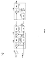
- FIG. 2 is a block diagram of an exemplary RF demodulator for a high-frequency receiver, in accordance with an embodiment of the invention.
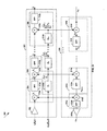
- FIG. 3 is a block diagram of an exemplary RF modulator and demodulator for a high-frequency transceiver, in accordance with an embodiment of the invention.
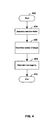
- FIG. 4 is a flowchart, illustrating an exemplary determination of the down conversion factors of a demodulator, in accordance with an embodiment of the invention.
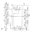
- FIG. 5 is a diagram of an exemplary demodulator with local oscillator frequency mixing, in accordance with an embodiment of the invention.
- Certain embodiments of the invention may be found in a method and system for a distributed transceiver for high frequency applications. Aspects of a method and system for a distributed transceiver for high frequency applications may comprise generating a second signal from a first signal by frequency-translating the first signal via a plurality of conversion stages. Each of the plurality of conversion stages may frequency-translate a corresponding input signal by a local oscillator frequency or by a fraction of said local oscillator frequency.
- the first signal may be the corresponding input signal to an initial stage of a the plurality of conversion stages
- an output signal of a previous one of the plurality of conversion stages may be the corresponding input signal to a subsequent one of the plurality of conversion stages
- the second signal may be an output signal of a final stage of the plurality of conversion stages.
- the plurality of conversion stages may be communicatively coupled in a cascade configuration.
- the first signal may be a radio frequency signal or an intermediate frequency signal and the second signal may be a baseband signal.
- the first signal may be a radio frequency signal or a baseband signal and the second signal may be an intermediate frequency signal.
- the first signal may be a baseband signal or an intermediate frequency signal and the second signal may be a radio frequency signal.
- the local oscillator frequency may be associated with a local oscillator signal and the fraction of the local oscillator frequency may be associated with a fractional local oscillator signal.
- the fractional local oscillator signal may be generated from the local oscillator signal by using one or more frequency dividers.
- Mixing the local oscillator and/or one or more mixing signals may generate the fractional local oscillator signal.
- the one or more mixing signals may be generated by dividing the local oscillator signal via one or more frequency dividers.
- the local oscillator may be a sinusoidal signal with a frequency equal to the local oscillator frequency.
- FIG. 1 is a diagram illustrating an exemplary wireless communication system, in connection with an embodiment of the invention.
- an access point 112b there is shown an access point 112b, a computer 110a, a headset 114a, a router 130, the Internet 132 and a web server 134.
- the computer or host device 110a may comprise a wireless radio 111a, a short-range radio 111b, a host processor 111c, and a host memory 111d.
- a wireless connection between the wireless radio 111a and the access point 112b and a short-range wireless connection between the short-range radio 111b and the headset 114a.
- computing and communication devices may comprise hardware and software to communicate using multiple wireless communication standards.
- the wireless radio 111a may be compliant with a mobile communications standard, for example.
- the wireless radio 111a and the short-range radio 111b may be active concurrently.
- the user may establish a wireless connection between the computer 110a and the access point 112b. Once this connection is established, the streaming content from the Web server 134 may be received via the router 130, the access point 112b, and the wireless connection, and consumed by the computer or host device 110a.
- the user of the computer 110a may establish a short-range wireless connection with the headset 114a. Once the short-range wireless connection is established, and with suitable configurations on the computer enabled, the audio portion of the streaming content may be consumed by the headset 114a.
- the radio frequency (RF) generation may support fast-switching to enable support of multiple communication standards and/or advanced wideband systems like, for example, Ultrawideband (UWB) radio.
- Other applications of short-range communications may be wireless High-Definition TV (W-HDTV), from a set top box to a video display, for example. W-HDTV may require high data rates that may be achieved with large bandwidth communication technologies, for example UWB and/or 60-GHz communications.
- FIG. 2 is a block diagram of an exemplary RF demodulator for a high-frequency receiver, in accordance with an embodiment of the invention.
- a demodulator 200 comprising an amplifier 202, and a plurality of down conversion stages, of which down conversion stages 204, 206 and 208 are illustrated.
- the down conversion stage 204 may comprise a multiplier 210a and a filter 212a.
- the down conversion stage 206 may comprise a multiplier 210b, a filter 212b and a frequency divider 214b.
- the down conversion stage 208 may comprise a multiplier 210c, a filter 212c and a frequency divider 214c.
- a received signal r 0 ( f 0 , t ) r 0 that may be a function of a carrier frequency f 0 and time t .
- the indices for frequency and time may be dropped for illustrative purposes.
- r 1 , r 2 , r K , r a , r b there is shown r 1 , r 2 , r K , r a , r b .
- a local oscillator signal c LO ( f LO , t ) c LO and a number of fractional local oscillator signals c LO / N 1 , c LO / N 1 N 2 , c LO / N 1 N 2 .
- the amplifier 202 may comprise suitable logic, circuitry and/or code that may be enabled to amplify a high-frequency RF signal at its input.
- the down conversion stages 204, 206 and 208 may be substantially similar and may comprise suitable logic, circuitry and/or code that may be enabled to down convert an input signal that may be modulated onto an RF carrier signal to an output signal that may be similar to the input signal but modulated onto lower frequency carrier signal.
- the multipliers 210a/b/c may comprise suitable logic, circuitry and/or code that may be enabled to multiply two RF input signals and generate an RF output signal that may be proportional to the product of its input signals.
- the filters 212a/b/c may comprise suitable logic, circuitry and/or code that may be enabled to attenuate a portion of the frequency spectrum of an input signal.
- the frequency dividers 214b/c may comprise suitable logic, circuitry and/or code that may be enabled to generate an output signal that may be similar to its input signal, divided in frequency.
- the frequency dividers may be implemented using Direct Digital Frequency Synthesis or integer (Miller) dividers, for example.
- the signal s ( t ) and the phase signal ⁇ ( t ) may be, for example, the information-bearing baseband signal and the information-bearing phase signal, respectively, that may be modulated onto the carrier cos( w 0 t ).
- r 0 ( f 0 ,t ) may be an inphase bandpass signal component and a similar block diagram as illustrated for demodulator 200 may also be used for a demodulator of a quadrature bandpass signal component.
- a local oscillator signal c LO for example with a Phase-locked loop (PLL), sufficiently high in frequency to achieve demodulation to baseband or, in some instances, to an intermediate frequency.
- PLL Phase-locked loop
- high frequency LO signals may generally be undesirable for distribution in a system since the signal transport over conductors may result in transmission line problems, due to the LO signal's high frequency content.
- a plurality of conversion stages for example down conversion stages 204, 206 and 208 may then be used to down convert the received signal r 0 to baseband and/or intermediate frequency.
- the signal r a may comprise a sum and a difference term at frequencies determined by the difference of the carrier frequency w 0 and the local oscillator frequency w LO .
- the generated signal r 1 may be down converted further. This may be achieved in a similar manner by down converting r 1 with a frequency-divided local oscillator signal.
- the divisor, N 1 applied in frequency divider 214b may be arbitrary. In many instances, it may be desirable to choose N 1 a rational number or an integer.
- Further down modulating may be achieved by applying further down conversion stages similar to down conversion stage 206, for example.
- the filters in the down conversion stages for example filters 212a/b/c may be filtering in order to attenuate the higher frequency component at their input.
- N k > 0 ⁇ k ⁇ 1,2,... K -1.
- the higher frequency component in r b may be retained by appropriately filtering r b in filter 212b.
- either the higher or the lower frequency component may be selected for each down conversion stage. As illustrated in equation (3), this may result in the sign of the frequency term corresponding to a particular down conversion stage to change.
- the output r K may be described by equation (2), wherein the coefficients N k may be positive or negative, as appropriate.
- Equation (4) may be stable and converge for an arbitrary number of stages when
- the frequency term in equation (5) may converge to w 0 t - 1. 3 ⁇ w LO t as K ⁇ ⁇ .
- the frequency term may already be w 0 t -1.3125 ⁇ w LO t and hence the frequency correction term may be approximately 1.3125 1.
- ⁇ 3 ⁇ 63 / 64 ⁇ 98.5 % of the desired frequency correction term.
- the number of down conversion stages may be arbitrary.
- the first down conversion stage for example down conversion stage 204 may comprise a frequency divider, similar, for example, to down conversion stage 206 and/or down conversion stage 208.
- the number of down conversion stages K may be determined, for example, based on the difference between w 0 and w LO , and the desired intermediate frequencies.
- the divisors may be software-programmable.
- the structure illustrated in FIG. 2 may be used by a modulator, whereby the sum terms instead of the difference terms may be retained in order to obtain an output signal at a higher frequency that the input signal.
- the higher frequency component may be retained by the filter 212b in the down conversion stage 206, whereby the down conversion stage 206 may effectively become an up conversion stage, as illustrated in equation (3).
- FIG. 3 is a block diagram of an exemplary RF modulator and demodulator for a high-frequency transceiver, in accordance with an embodiment of the invention.
- a modulator/demodulator system 300 comprising a demodulator 320 and a modulator 330.
- the demodulator 320 may be substantially similar to the demodulator 200 illustrated in FIG. 2 .
- the elements of demodulator 320 may be similar to their corresponding elements in demodulator 200.
- elements 302, 304, 306, 308, 310a/b/c, 312a/b/c and 314b/c may be similar to elements 202, 204, 206, 208, 210a/b/c, 212 a/b/c and 214 b/c, respectively.
- the modulator 330 may comprise an amplifier 302a, and a plurality of up conversion stages, of which up conversion stages 304a, 306a and 308a may be illustrated.
- the modulator 330 may comprise suitable logic, circuitry and/or code that may be enabled to modulate an input signal, r T 0 , to radio frequency, r TK .
- the subscript 'T' may indicate a transmit signal associated with the modulator 330.
- the up conversion stage 304a, 306a and 308a may comprise filters 312d/e/f and multipliers 310d/e/f, respectively.
- a transmit signal r T 0 ( f T 0 , t ) r T 0 that may be a function of frequency f T 0 and time t .
- the indices for frequency and time may be dropped for illustrative purposes.
- r T 1 , r T ( K -1) , r TK which may be the output signals of up conversion stages 1,( K -1) and K , respectively.
- the functionality of the modulator 330 may be considered similar to the demodulator 320 functionality in reverse.
- the input signal r 0 may be a signal modulated onto a radio frequency carrier or an intermediate frequency carrier for frequency translation to a lower frequency
- the input signal of the modulator 330 may be a baseband signal or an intermediate frequency signal for frequency translation to a higher frequency, for example to intermediate frequency or radio frequency, respectively.
- the frequency up conversion may be achieved similarly to the frequency down conversion.
- the main difference may be found in the filtering, wherein the higher frequency components may be retained, as described for equation (3) and FIG. 2 .
- the modulator 330 may share the frequency dividers, for example frequency dividers 314b/c, with the demodulator 320, the modulator 330 may be configured in a manner that may provide the same up conversion frequency steps that may be provided in the down conversion.
- the filter in a down conversion stage may retain the lower frequency component, by retaining the higher frequency component in the corresponding up conversion stage, the up conversion signal may be upconverted in frequency by the same amount as a down conversion signal may be downconverted in frequency by the corresponding down conversion stage. For example, as described for FIG.
- the frequency translation across the entire modulator may be chosen approximately equal across the entire demodulator, for example, in opposite directions.
- the received signal r 0 may be down converted by 40 GHz from r 0 to r K , and the transmit signal r T 0 may be up converted by 40 GHz from at r T 0 to r TK .
- the high-frequency transceiver in FIG. 3 may operate in a time division duplex (TDD) mode, whereby a signal may be generated for transmission in the modulator 330, for example r TK , or a signal may be received in demodulator 320, for example r 0 .
- TDD time division duplex
- the high-frequency transceiver 300 may either be receiving or transmitting, but not both, in accordance with an embodiment of the invention.
- the frequency dividers for example the frequency divider 314b and/or 314c, may be programmable and may use different divisors N , depending on whether the transceiver may be in transmit or receive mode.
- the transmit carrier frequency f K for the transmit signal r TK ( f K , t ) may be chosen different from the receive frequency f 0 in the receive signal r 0 in some instances.
- sharing programmable frequency dividers as illustrated in FIG. 3 may permit the transceiver system 300 to operate in a combined TDD/FDD mode, where different frequencies may be used in the modulator 330 and the demodulator 320, depending on the operation mode that may change as a function of time.
- FIG. 4 is a flowchart, illustrating an exemplary determination of the down conversion factors of a demodulator, in accordance with an embodiment of the invention.
- FIG. 4 it is understood by one skilled in the art that there are a large number of approaches that may be chosen to determine a number of frequency conversion stages and appropriate frequency conversion factors.
- FIG. 4 there is shown one approach that may be used to determine a number of frequency conversion stages and the associated conversion factors and/or divisors.
- a reduction factor may be determined.
- the reduction factor for example x
- the reduction factor may be determined by the difference between the frequency of the carrier of the received signal, w 0 , and the desired carrier frequency at the output of the demodulator, w K .
- the down conversion factor N K of the K-th down conversion stage may correspondingly be chosen, in step 408, as 0 ⁇ N K ⁇ 1 and may be given by the following relationship: N K ⁇ 1 x - ⁇ x ⁇ where the operation ⁇ . ⁇ may denote 'the nearest smaller integer', and the operation ' ⁇ ' may be interpreted as 'a sufficiently close rational number', in accordance with the accuracy that may be required in the system.
- the target frequency w K may be 1 GHz
- the local oscillator frequency w LO may be 8 GHz
- x 7.375.
- K 8 stages.
- FIG. 5 is a diagram of an exemplary demodulator with local oscillator frequency mixing, in accordance with an embodiment of the invention.
- a demodulation system 500 comprising an amplifier 502, down conversion stages 504, 506 and 508, an LO mixer 520 and a fractional LO cascade 530.
- the down conversion stages 504, 506 and 508 may comprise multipliers 510a/b/c and filters 512a/b/c, respectively.
- the LO mixer 520 may comprise filters 512d/e and multipliers 510d/e.
- the fractional LO cascade 530 may comprise frequency dividers 514a/b/c.
- a received signal r o ( f 0 , t ) r 0 that may be a function of a receive carrier frequency f 0 and time t .
- the indices for frequency and time may be dropped for illustrative purposes.
- r 1 , r 2 ,r 3 , r a , r b, r c , r m 1 , r m 2 , r m 3 there is shown.
- the type of frequency divider for example 214b/c, may be constrained due to a particular implementation.
- N k ⁇ + may be possible.
- the divisors may be chosen only from among the set of positive integers.
- N N - 1 may be chosen as an integer greater or equal to 2, arbitrary accuracy may be achieved easily.
- an LO mixer 520 may be used together with the fractional LO cascade 530.
- the fractional LO cascade 530 may comprise suitable logic, circuitry and/or code that may be enabled to accept a local oscillator input signal c LO ( f LO , t ) and frequency divide it in a cascade of frequency dividers, for example 514a/b/c, to generate fractional local oscillator signals, for example c LO ( f LO / N , t ), c LO (f LO / N 2 , t ) and c LO ( f LO / N 3 , t ), respectively.
- fractional local oscillator signals By appropriately mixing these fractional local oscillator signals, small frequency differences may be generated that may be used in the down conversion stages.
- the resolution, or frequency steps, obtainable may depend on the number of frequency dividers in the fractional LO cascade 530.
- arbitrary down conversion factors By appropriately multiplying and filtering various fractional LO terms obtained in the fractional LO cascade 530 in the LO mixer 520, arbitrary down conversion factors may be achieved in the down conversion stages, for a sufficient number of frequency dividers in the LO cascade 530.
- the exemplary embodiment illustrated in FIG. 5 may result in an overall down conversion factor of 4.125, that is, r 3 ⁇ cos( w 0 t + ⁇ ( t )-4.125 w L O t ).
- the filter 512d may retain the low-frequency or high frequency component.
- the signal r m 1 may be communicatively coupled to the multiplier 510a in the down conversion stage 504.
- the output of frequency divider 514b may be directly coupled to the down conversion stage 506 and may not be mixed beforehand in the LO mixer 520.
- the output of the frequency divider 514a may not be coupled to the LO mixer 520 or a down conversion stage, in this embodiment of the invention. Instead, the output of frequency divider 514a may be used as the input to the frequency divider 514b.
- the output of the frequency divider 514c may be communicatively coupled to an input of the multiplier 510e.
- the second input of the multiplier 510e may be coupled to the output of the filter 512d.
- z may be the amplification factor introduced by amplifier 502, similar to the description for FIG. 2 .
- the output signal r 3 that may be generated by the down conversion stages may be frequency translated by a factor of 4.125.
- an arbitrary down conversion (frequency translation) factor may be achieved.
- a similar approach may be used for a modulator by appropriate filtering in the conversion stages 504, 506 and 508, as described above and with respect to FIG. 2 .
- a method and system for a distributed transceiver for high frequency applications may comprise generating a second signal from a first signal for example r K , by frequency-translating the first signal, for example r 0 , via a plurality of conversion stages, as illustrated in FIG.2 , FIG. 3 and FIG. 5 .
- Each of the plurality of conversion stages for example conversion stages 204, 206 and 208, may frequency-translate a corresponding input signal by a local oscillator frequency or by a fraction of said local oscillator frequency, as described for FIG. 2 .
- the first signal may be the corresponding input signal to an initial stage of a the plurality of conversion stages
- an output signal of a previous one of the plurality of conversion stages may be the corresponding input signal to a subsequent one of the plurality of conversion stages
- the second signal may be an output signal of a final stage of the plurality of conversion stages.
- the plurality of conversion stages may be communicatively coupled in a cascade configuration, as illustrated in FIG. 5 .
- the first signal may be a radio frequency signal or an intermediate frequency signal and the second signal may be a baseband signal.
- the first signal may be a radio frequency signal or a baseband signal and the second signal may be an intermediate frequency signal.
- the first signal may be a baseband signal or an intermediate frequency signal and the second signal may be a radio frequency signal, as described for FIG. 2 .
- the local oscillator frequency for example w LO .
- the fractional local oscillator signal may be generated from the local oscillator c LO signal by using one or more frequency dividers, for example 514a/b/c. Mixing the local oscillator and/or one or more mixing signals may generate the fractional local oscillator signal, as illustrated in FIG. 2 , for example.
- the one or more mixing signals may be generated by dividing the local oscillator signal via one or more frequency dividers.
- the local oscillator may be a sinusoidal signal with a frequency equal to the local oscillator frequency.
- Another embodiment of the invention may provide a machine-readable storage, having stored thereon, a computer program having at least one code section executable by a machine, thereby causing the machine to perform the steps as described above for a method and system for a distributed transceiver for high frequency applications.
- the present invention may be realized in hardware, software, or a combination of hardware and software.
- the present invention may be realized in a centralized fashion in at least one computer system, or in a distributed fashion where different elements are spread across several interconnected computer systems. Any kind of computer system or other apparatus adapted for carrying out the methods described herein is suited.
- a typical combination of hardware and software may be a general-purpose computer system with a computer program that, when being loaded and executed, controls the computer system such that it carries out the methods described herein.
- the present invention may also be embedded in a computer program product, which comprises all the features enabling the implementation of the methods described herein, and which when loaded in a computer system is able to carry out these methods.
- Computer program in the present context means any expression, in any language, code or notation, of a set of instructions intended to cause a system having an information processing capability to perform a particular function either directly or after either or both of the following: a) conversion to another language, code or notation; b) reproduction in a different material form.
Landscapes
- Engineering & Computer Science (AREA)
- Power Engineering (AREA)
- Computer Networks & Wireless Communication (AREA)
- Signal Processing (AREA)
- Transceivers (AREA)
- Superheterodyne Receivers (AREA)
- Transmitters (AREA)
Abstract
Description
- This application makes reference to:
- United States Application Serial No. (Attorney Docket No. 18760US01), filed on even date herewith;
- United States Application Serial No. (Attorney Docket No. 18761US01), filed on even date herewith;
- United States Application Serial No. (Attorney Docket No. 18759US01), filed on even date herewith;
- United States Application Serial No. (Attorney Docket No. 18762US01), filed on even date herewith; and
- United States Application Serial No. (Attorney Docket No. 18766US01), filed on even date herewith.
- Each of the above referenced applications is hereby incorporated herein by reference in its entirety.
- Certain embodiments of the invention relate to signal processing for communication systems. More specifically, certain embodiments of the invention relate to a method and system for a distributed transceiver for high frequency applications.
- In 2001, the Federal Communications Commission (FCC) designated a large contiguous block of 7 GHz bandwidth for communications in the 57 GHz to 64 GHz spectrum. This frequency band was designated for use on an unlicensed basis, that is, the spectrum is accessible to anyone, subject to certain basic, technical restrictions such as maximum transmission power and certain coexistence mechanisms. The communications taking place in this band are often referred to as '60 GHz communications'.
- With respect to the accessibility of this designated portion of the spectrum, 60 GHz communications is similar to other forms of unlicensed spectrum use, for example Wireless LANs or Bluetooth in the 2.4 GHz ISM bands. However, communications at 60 GHz may be significantly different in aspects other than accessibility. For example, 60 GHz signals may provide markedly different communications channel and propagation characteristics, at least due to the fact that 60 GHz radiation is partly absorbed by oxygen in the air, leading to higher attenuation with distance. On the other hand, since a very large bandwidth of 7 GHz is available, very high data rates may be achieved. Among the applications for 60 GHz communications are wireless personal area networks, wireless high-definition television signal, for example from a set top box to a display, or Point-to-Point links.
- Further limitations and disadvantages of conventional and traditional approaches will become apparent to one of skill in the art, through comparison of such systems with some aspects of the present invention as set forth in the remainder of the present application with reference to the drawings.
- A method and/or system for a distributed transceiver for high frequency applications, substantially as shown in and/or described in connection with at least one of the figures, as set forth more completely in the claims.
According to an aspect, a method is provided for processing communication signals, the method comprising: - generating a second signal from a first signal by:
- frequency-translating said first signal via a plurality of conversion stages, wherein:
- each of said plurality of conversion stages frequency-translates a corresponding input signal by a local oscillator frequency or by a fraction of said local oscillator frequency; and
- said first signal is said corresponding input signal to an initial stage of a said plurality of conversion stages, an output signal of a previous one of said plurality of conversion stages is said corresponding input signal to a subsequent one of said plurality of conversion stages, and said second signal is an output signal of a final stage of said plurality of conversion stages.
- frequency-translating said first signal via a plurality of conversion stages, wherein:
- Advantageously, said plurality of conversion stages are communicatively coupled in a cascade configuration.
- Advantageously, said first signal is a radio frequency signal or an intermediate frequency signal and said second signal is a baseband signal.
- Advantageously, said first signal is a radio frequency signal or a baseband signal and said second signal is an intermediate frequency signal.
- Advantageously, said first signal is a baseband signal or an intermediate frequency signal and said second signal is a radio frequency signal.
- Advantageously, said local oscillator frequency is associated with a local oscillator signal and said fraction of said local oscillator frequency is associated with a fractional local oscillator signal
- Advantageously, the method further comprises generating said fractional local oscillator signal from said local oscillator signal by using one or more frequency dividers.
- Advantageously, the method further comprises mixing said local oscillator signal and/or one or more mixing signals to generate said fractional local oscillator signal.
- Advantageously, the method further comprises dividing said local oscillator signal via one or more frequency dividers to generate said one or more mixing signals.
- Advantageously, said local oscillator signal is a sinusoidal signal with a frequency equal to said local oscillator frequency.
- According to an aspect, a system is provided for processing communication signals, the system comprising:
- one or more circuits, said one or more circuits enabled to generate a second signal from a first signal by:
- frequency-translating said first signal via a plurality of conversion stages, wherein:
- each of said plurality of conversion stages frequency-translates a corresponding input signal by a local oscillator frequency or by a fraction of said local oscillator frequency; and
- said first signal is said corresponding input signal to an initial stage of a said plurality of conversion stages, an output signal of a previous one of said plurality of conversion stages is said corresponding input signal to a subsequent one of said plurality of conversion stages, and said second signal is an output signal of a final stage of said plurality of conversion stages.
- frequency-translating said first signal via a plurality of conversion stages, wherein:
- Advantageously, said plurality of conversion stages are communicatively coupled in a cascade configuration.
- Advantageously, said first signal is a radio frequency signal or an intermediate frequency signal and said second signal is a baseband signal.
- Advantageously, said first signal is a radio frequency signal or a baseband signal and said second signal is an intermediate frequency signal.
- Advantageously, said first signal is a baseband signal or an intermediate frequency signal and said second signal is a radio frequency signal.
- Advantageously, said local oscillator frequency is associated with a local oscillator signal and said fraction of said local oscillator frequency is associated with a fractional local oscillator signal.
- Advantageously, said one or more circuits generate said fractional local oscillator signal from said local oscillator signal by using one or more frequency dividers.
- Advantageously, said one or more circuits mix said local oscillator signal and/or one or more mixing signals to generate said fractional local oscillator signal.
- Advantageously, said one or more circuits divide said local oscillator signal via one or more frequency dividers to generate said one or more mixing signals.
- Advantageously, said local oscillator signal is a sinusoidal signal with a frequency equal to said local oscillator frequency.
- These and other advantages, aspects and novel features of the present invention, as well as details of an illustrated embodiment thereof, will be more fully understood from the following description and drawings.
-
FIG. 1 is a diagram illustrating an exemplary wireless communication system, in connection with an embodiment of the invention. -
FIG. 2 is a block diagram of an exemplary RF demodulator for a high-frequency receiver, in accordance with an embodiment of the invention. -
FIG. 3 is a block diagram of an exemplary RF modulator and demodulator for a high-frequency transceiver, in accordance with an embodiment of the invention. -
FIG. 4 is a flowchart, illustrating an exemplary determination of the down conversion factors of a demodulator, in accordance with an embodiment of the invention. -
FIG. 5 is a diagram of an exemplary demodulator with local oscillator frequency mixing, in accordance with an embodiment of the invention. - Certain embodiments of the invention may be found in a method and system for a distributed transceiver for high frequency applications. Aspects of a method and system for a distributed transceiver for high frequency applications may comprise generating a second signal from a first signal by frequency-translating the first signal via a plurality of conversion stages. Each of the plurality of conversion stages may frequency-translate a corresponding input signal by a local oscillator frequency or by a fraction of said local oscillator frequency. The first signal may be the corresponding input signal to an initial stage of a the plurality of conversion stages, an output signal of a previous one of the plurality of conversion stages may be the corresponding input signal to a subsequent one of the plurality of conversion stages, and the second signal may be an output signal of a final stage of the plurality of conversion stages.
- The plurality of conversion stages may be communicatively coupled in a cascade configuration. The first signal may be a radio frequency signal or an intermediate frequency signal and the second signal may be a baseband signal. The first signal may be a radio frequency signal or a baseband signal and the second signal may be an intermediate frequency signal. The first signal may be a baseband signal or an intermediate frequency signal and the second signal may be a radio frequency signal. The local oscillator frequency may be associated with a local oscillator signal and the fraction of the local oscillator frequency may be associated with a fractional local oscillator signal. The fractional local oscillator signal may be generated from the local oscillator signal by using one or more frequency dividers. Mixing the local oscillator and/or one or more mixing signals may generate the fractional local oscillator signal. The one or more mixing signals may be generated by dividing the local oscillator signal via one or more frequency dividers. The local oscillator may be a sinusoidal signal with a frequency equal to the local oscillator frequency.
-
FIG. 1 is a diagram illustrating an exemplary wireless communication system, in connection with an embodiment of the invention. Referring toFIG. 1 , there is shown anaccess point 112b, acomputer 110a, a headset 114a, arouter 130, theInternet 132 and aweb server 134. The computer orhost device 110a may comprise awireless radio 111a, a short-range radio 111b, ahost processor 111c, and ahost memory 111d. There is also shown a wireless connection between thewireless radio 111a and theaccess point 112b, and a short-range wireless connection between the short-range radio 111b and the headset 114a. - Frequently, computing and communication devices may comprise hardware and software to communicate using multiple wireless communication standards. The
wireless radio 111a may be compliant with a mobile communications standard, for example. There may be instances when thewireless radio 111a and the short-range radio 111b may be active concurrently. For example, it may be desirable for a user of the computer orhost device 110a to access theInternet 132 in order to consume streaming content from theWeb server 134. Accordingly, the user may establish a wireless connection between thecomputer 110a and theaccess point 112b. Once this connection is established, the streaming content from theWeb server 134 may be received via therouter 130, theaccess point 112b, and the wireless connection, and consumed by the computer orhost device 110a. - It may be further desirable for the user of the
computer 110a to listen to an audio portion of the streaming content on the headset 114a. Accordingly, the user of thecomputer 110a may establish a short-range wireless connection with the headset 114a. Once the short-range wireless connection is established, and with suitable configurations on the computer enabled, the audio portion of the streaming content may be consumed by the headset 114a. In instances where such advanced communication systems are integrated or located within thehost device 110a, the radio frequency (RF) generation may support fast-switching to enable support of multiple communication standards and/or advanced wideband systems like, for example, Ultrawideband (UWB) radio. Other applications of short-range communications may be wireless High-Definition TV (W-HDTV), from a set top box to a video display, for example. W-HDTV may require high data rates that may be achieved with large bandwidth communication technologies, for example UWB and/or 60-GHz communications. -
FIG. 2 is a block diagram of an exemplary RF demodulator for a high-frequency receiver, in accordance with an embodiment of the invention. Referring toFIG. 2 , there is shown ademodulator 200 comprising anamplifier 202, and a plurality of down conversion stages, of which down conversion stages 204, 206 and 208 are illustrated. The downconversion stage 204 may comprise amultiplier 210a and afilter 212a. The downconversion stage 206 may comprise amultiplier 210b, afilter 212b and a frequency divider 214b. The downconversion stage 208 may comprise amultiplier 210c, afilter 212c and afrequency divider 214c. There is also shown a received signal r 0(f 0,t) = r0 that may be a function of a carrier frequency f 0 and time t . The indices for frequency and time may be dropped for illustrative purposes. Similarly, there is shown r 1,r 2,rK ,ra ,rb . A local oscillator signal cLO (fLO ,t) = cLO and a number of fractional local oscillator signals c LO/N1,c LO/N1N2,c LO/N1N2...NK with frequency terms

- The
amplifier 202 may comprise suitable logic, circuitry and/or code that may be enabled to amplify a high-frequency RF signal at its input. The down conversion stages 204, 206 and 208 may be substantially similar and may comprise suitable logic, circuitry and/or code that may be enabled to down convert an input signal that may be modulated onto an RF carrier signal to an output signal that may be similar to the input signal but modulated onto lower frequency carrier signal. Themultipliers 210a/b/c may comprise suitable logic, circuitry and/or code that may be enabled to multiply two RF input signals and generate an RF output signal that may be proportional to the product of its input signals. Thefilters 212a/b/c may comprise suitable logic, circuitry and/or code that may be enabled to attenuate a portion of the frequency spectrum of an input signal. The frequency dividers 214b/c may comprise suitable logic, circuitry and/or code that may be enabled to generate an output signal that may be similar to its input signal, divided in frequency. The frequency dividers may be implemented using Direct Digital Frequency Synthesis or integer (Miller) dividers, for example. - With reference to
FIG. 2 , there is shown ademodulator 200 that may be part of a high-frequency radio frequency receiver. An exemplary high-frequency received signal may be r 0(f 0,t)=s(t)cos(2πf 0 t+φ(t))=s(t)cos(w 0 t+φ(t)), where f 0 may be the carrier frequency and 2πf 0 = w 0 may be the corresponding angular frequency. The signal s(t) and the phase signal φ(t) may be, for example, the information-bearing baseband signal and the information-bearing phase signal, respectively, that may be modulated onto the carrier cos(w 0 t). In this instance, r 0(f 0 ,t) may be an inphase bandpass signal component and a similar block diagram as illustrated fordemodulator 200 may also be used for a demodulator of a quadrature bandpass signal component. In some instances, the received signal r 0 may be at a high carrier frequency, for example, f 0 = 60 GHz. In these instances, it may be difficult to generate a local oscillator signal cLO, for example with a Phase-locked loop (PLL), sufficiently high in frequency to achieve demodulation to baseband or, in some instances, to an intermediate frequency. In addition, high frequency LO signals may generally be undesirable for distribution in a system since the signal transport over conductors may result in transmission line problems, due to the LO signal's high frequency content. Hence, it may be desirable to generate the high frequency signal for demodulation of the RF signal in proximity to the received high frequency signal r 0(f 0,t). In these instances, it may be desirable to generate a local oscillator signal cLO that may be significantly lower in frequency, for example, fLO = 20 GHz, than the carrier of the received signal at, for example f 0 = 60 GHz. In accordance with various embodiments of the invention, a plurality of conversion stages, for example down conversion stages 204, 206 and 208 may then be used to down convert the received signal r 0 to baseband and/or intermediate frequency. - An exemplary received signal r 0 may be amplified by a factor z in the
amplifier 202 to generate a signal at the input to themultiplier 210a, given by r' 0(f 0,t)=z·r 0 (f 0,t)=z·s(t)cos(w 0 t+φ(t)). Themultiplier 210a may multiply the signals r'0 with the local oscillator signal cLO = cos(wLOt), to generate ra according to the following relationship:
Hence, as may be seen from the above equation, the signal ra may comprise a sum and a difference term at frequencies determined by the difference of the carrier frequency w 0 and the local oscillator frequency wLO . In this instance, in accordance with an embodiment of the invention, it may be desirable to demodulate the received signal r 0 and hence it may be desirable to retain only the lower frequency component, modulated onto a carrier at frequency w 0 - wLO . This may be achieved by thefilter 212a, which may reject the higher of the frequency terms to generate r 1, given by the following relationship:
- In an additional down conversion stage, for example down
conversion stage 206, the generated signal r 1,may be down converted further. This may be achieved in a similar manner by down converting r 1 with a frequency-divided local oscillator signal. Specifically, as illustrated inFIG. 2 , the down converted output signal r 1 from downconversion stage 204 may be multiplied with a signal that may be a frequency divided version of the local oscillator at the output of the frequency divider 214b, namely
multiplier 210b that may be given by the following relationship:
Similar to generating r 1, r 2 at the output of thedown conversion stage 206 may be generated by applying suitable filtering to rb , which may remove the higher frequency component infilter 212b, to obtain:
- Further down modulating may be achieved by applying further down conversion stages similar to
down conversion stage 206, for example. As illustrated inFIG. 2 , it may be desirable to use a cascade of K down conversion stages. In this case, the output signal rK after K down conversion stages may be given, for example, by the following relationship:
In these instances, it may be that the filters in the down conversion stages, forexample filters 212a/b/c may be filtering in order to attenuate the higher frequency component at their input. In this instance, Nk > 0 ∀k ∈1,2,...K-1. - In some instances and for some down conversion stages, it may be desirable to choose to retain the higher frequency component rather than the lower frequency component of the output signal of the multiplier, in order to get a desirable output at the filter. For example, in accordance with various embodiments of the invention, the higher frequency component in rb , equation (1), for example, may be retained by appropriately filtering rb in
filter 212b. In this instance, from equation (1), r 2 may be given by the following relationship:
- In a general case, either the higher or the lower frequency component may be selected for each down conversion stage. As illustrated in equation (3), this may result in the sign of the frequency term corresponding to a particular down conversion stage to change. Hence, for K down conversion stages, the output rK may be described by equation (2), wherein the coefficients Nk may be positive or negative, as appropriate.
- In one embodiment of the invention, the divisors Nk may be chosen equal, so that Nk = N ∀k. In these instances, equation (2) may be given by the following relationship:

- By choosing z = 2 K , which may be achieved, for example, by amplifying by a factor of two at each down conversion stage, it may be observed that the expression in equation (4) may be stable and converge for an arbitrary number of stages when |1/N|<1, so that the limit of (4) may be given by the following relationship:

where equation (5) may converge more rapidly for larger N. For example, if N = 4 , the frequency term in equation (5) may converge to w 0 t - 1.3 ·wLOt as K → ∞. However, as may be observed from the first line of equation (5), with K = 3, the frequency term may already be w 0 t-1.3125·wLOt and hence the frequency correction term may be approximately
- In accordance with various embodiments of the invention, the number of down conversion stages may be arbitrary. Moreover, in some instances, it may be desirable that the first down conversion stage, for example down
conversion stage 204 may comprise a frequency divider, similar, for example, to downconversion stage 206 and/or downconversion stage 208. The number of down conversion stages K may be determined, for example, based on the difference between w 0 and wLO , and the desired intermediate frequencies. In some instances, it may be possible that the divisors may be software-programmable. Moreover, the structure illustrated inFIG. 2 may be used by a modulator, whereby the sum terms instead of the difference terms may be retained in order to obtain an output signal at a higher frequency that the input signal. For example, in equation (1), the higher frequency component may be retained by thefilter 212b in thedown conversion stage 206, whereby thedown conversion stage 206 may effectively become an up conversion stage, as illustrated in equation (3). -
FIG. 3 is a block diagram of an exemplary RF modulator and demodulator for a high-frequency transceiver, in accordance with an embodiment of the invention. Referring toFIG. 3 , there is shown a modulator/demodulator system 300 comprising ademodulator 320 and amodulator 330. Thedemodulator 320 may be substantially similar to thedemodulator 200 illustrated inFIG. 2 . The elements ofdemodulator 320 may be similar to their corresponding elements indemodulator 200. Specifically,elements elements - The
modulator 330 may comprise anamplifier 302a, and a plurality of up conversion stages, of which upconversion stages modulator 330 may comprise suitable logic, circuitry and/or code that may be enabled to modulate an input signal, r T0, to radio frequency, rTK . The subscript 'T' may indicate a transmit signal associated with themodulator 330. The upconversion stage filters 312d/e/f andmultipliers 310d/e/f, respectively. There is also shown a transmit signal r T0(f T0,t)=r T0 that may be a function of frequency f T0 and time t. The indices for frequency and time may be dropped for illustrative purposes. Similarly, there is shown r T1,r T(K-1),rTK , which may be the output signals of up conversion stages 1,(K-1) and K, respectively. - The functionality of the
modulator 330 may be considered similar to thedemodulator 320 functionality in reverse. In particular, whereas in thedemodulator 320, the input signal r 0 may be a signal modulated onto a radio frequency carrier or an intermediate frequency carrier for frequency translation to a lower frequency, the input signal of themodulator 330 may be a baseband signal or an intermediate frequency signal for frequency translation to a higher frequency, for example to intermediate frequency or radio frequency, respectively. However, the frequency up conversion may be achieved similarly to the frequency down conversion. The main difference may be found in the filtering, wherein the higher frequency components may be retained, as described for equation (3) andFIG. 2 . For example, in upconversion stage 308a, the output signal r T1 may be given by the following relationship:
where w T0=2πf T0 may be the angular frequency of the input signal r T0 =x(t)cos(w T0 t+Φ(t)), wherein x(t) may be the information bearing baseband signal, and Φ(t) may be the information-bearing phase signal, similar to s(t) and φ(t), respectively, for the received signal. For an up conversion stage, for example upconversion stage 308a, thefilter 312f may maintain, for example, the higher of the frequency components of rTa from equation (6), so that rT1 may be given by the following relationship:
Similar toFIG. 2 , thefilter 312f may be an arbitrary filter and may retain, for example, the lower and/or higher frequency components comprised in its input signal, and may not be limited to the expression provided in equation (7). - In accordance with an embodiment of the invention, the
modulator 330 may share the frequency dividers, for example frequency dividers 314b/c, with thedemodulator 320, themodulator 330 may be configured in a manner that may provide the same up conversion frequency steps that may be provided in the down conversion. In particular, if the filter in a down conversion stage may retain the lower frequency component, by retaining the higher frequency component in the corresponding up conversion stage, the up conversion signal may be upconverted in frequency by the same amount as a down conversion signal may be downconverted in frequency by the corresponding down conversion stage. For example, as described forFIG. 2 , the received signal r 0 may be down converted from angular frequency w 0 to w 1 = w0 - wLO for signal r 1 indown conversion stage 304. Similarly, the signal r T(K-1) at angular frequency w T(K-1) may be converted by the corresponding upconversion stage 304a to angular frequency wTK = w T(K-1) + wLO . Hence, by appropriately choosing the filters in both thedemodulator 320 and themodulator 330, the frequency translation across the entire modulator may be chosen approximately equal across the entire demodulator, for example, in opposite directions. In one exemplary embodiment of the invention, the received signal r 0, for example, may be down converted by 40 GHz from r 0 to r K , and the transmit signal r T0 may be up converted by 40 GHz from at r T0 to rTK. - In some instances, the high-frequency transceiver in
FIG. 3 may operate in a time division duplex (TDD) mode, whereby a signal may be generated for transmission in themodulator 330, for example rTK , or a signal may be received indemodulator 320, for example r 0. At any instance in time, the high-frequency transceiver 300 may either be receiving or transmitting, but not both, in accordance with an embodiment of the invention. In these instances, the frequency dividers, for example the frequency divider 314b and/or 314c, may be programmable and may use different divisors N , depending on whether the transceiver may be in transmit or receive mode. Accordingly, because different divisors may be used as a function of the mode of operation, the transmit carrier frequency fK for the transmit signal rTK (fK ,t) may be chosen different from the receive frequency f 0 in the receive signal r 0 in some instances. In this mode of operation, sharing programmable frequency dividers as illustrated inFIG. 3 may permit thetransceiver system 300 to operate in a combined TDD/FDD mode, where different frequencies may be used in themodulator 330 and thedemodulator 320, depending on the operation mode that may change as a function of time. -
FIG. 4 is a flowchart, illustrating an exemplary determination of the down conversion factors of a demodulator, in accordance with an embodiment of the invention. In accordance with the description forFIG. 2 andFIG. 3 , it is understood by one skilled in the art that there are a large number of approaches that may be chosen to determine a number of frequency conversion stages and appropriate frequency conversion factors. With reference toFIG. 4 , there is shown one approach that may be used to determine a number of frequency conversion stages and the associated conversion factors and/or divisors. - In accordance with an exemplary embodiment of the invention, determination of a down conversion system, for example a demodulator similar to
FIG. 2 , may be illustrated inFIG. 4 . Initially, instep 404, a reduction factor may be determined. The reduction factor, for example x , may be determined by the difference between the frequency of the carrier of the received signal, w 0, and the desired carrier frequency at the output of the demodulator, wK . The reduction factor may be expressed in terms of local oscillator frequency, as given by the following relationship:
- Based on the reduction factor, the number of stages according to this exemplary approach may be determined as given by the following relationship, in step 406:

where the operation ┌.┐ may denote 'the nearest greater integer'. In this instance, for K conversion stages, K-1 conversion stages may be chosen such that Nk = 1 ∀k ∈ 0,1,...K-1. The down conversion factor NK of the K-th down conversion stage may correspondingly be chosen, instep 408, as 0<NK <1 and may be given by the following relationship:
where the operation └.┘ may denote 'the nearest smaller integer', and the operation '≈' may be interpreted as 'a sufficiently close rational number', in accordance with the accuracy that may be required in the system. - In an exemplary embodiment of the invention, in instances where w 0 may be 60 GHz, the target frequency wK may be 1 GHz, and the local oscillator frequency wLO may be 8 GHz, x=7.375. Hence, it may be desirable to use K=8 stages. Hence, Nk =1 ∀k ∈ 0,1,...6 and

-
FIG. 5 is a diagram of an exemplary demodulator with local oscillator frequency mixing, in accordance with an embodiment of the invention. Referring toFIG. 5 , there is shown ademodulation system 500 comprising anamplifier 502, down conversion stages 504, 506 and 508, anLO mixer 520 and afractional LO cascade 530. The down conversion stages 504, 506 and 508 may comprisemultipliers 510a/b/c andfilters 512a/b/c, respectively. TheLO mixer 520 may comprisefilters 512d/e andmultipliers 510d/e. Thefractional LO cascade 530 may comprisefrequency dividers 514a/b/c. There is also shown a received signal ro (f 0,t) = r 0 that may be a function of a receive carrier frequency f 0 and time t. The indices for frequency and time may be dropped for illustrative purposes. Similarly, there is shown r1,r 2 ,r 3,ra ,rb,rc ,r m1,r m2,r m3 . A local oscillator signal cLO (f LO, t)=cLO may be shown and a number of frequency terms

- In some instances, the type of frequency divider, for example 214b/c, may be constrained due to a particular implementation. For example, it may be possible that Nk ∈□+. In this regard, the divisors may be chosen only from among the set of positive integers. In another embodiment of the invention illustrated in
FIG. 5 , the frequency divider may be more constrained and Nk = N ∀k, for example. Notwithstanding, in accordance with an embodiment of the invention, high precision may be achieved even for fixed Nk = N , in some instances at the expense of anLO mixer 520. For example, when N = Nk = 2 ∀k, from equation (5), for example, one may see that the frequency term may converge to

K Correction term 
Error term w.r.t K = ∞ (in %) Difference between adjacent stages 0 1 50 1 1 1.5 25 0.5 2 1.75 12.5 0.25 3 1.875 6.25 0.125 4 1.9375 3.125 0.0625 5 1.96875 1.5625 0.03125 6 1.984375 0.78125 0.015625 7 1.992188 0.390625 0.007813 8 1.996094 0.195313 0.003906 9 1.998047 0.097656 0.001953 10 1.999023 0.048828 0.000977 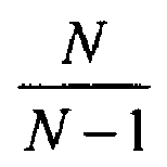
FIG. 2 , to approximate a correction factor of 5 = 3+2, stages Nk =1;k∈0,1,2, to obtain the factor 3, followed by an arbitrary number of stages with Nk = 2 ∀k : k > 2, to get arbitrarily close to 5. - In order to generate arbitrary frequency correction terms based on a fixed divisor factor Nk = N ∀k, an
LO mixer 520 may be used together with thefractional LO cascade 530. Thefractional LO cascade 530 may comprise suitable logic, circuitry and/or code that may be enabled to accept a local oscillator input signal cLO (fLO ,t) and frequency divide it in a cascade of frequency dividers, for example 514a/b/c, to generate fractional local oscillator signals, for example cLO (fLO /N,t),cLO(fLO /N2 ,t) and cLO (fLO /N3 ,t), respectively. By appropriately mixing these fractional local oscillator signals, small frequency differences may be generated that may be used in the down conversion stages. The resolution, or frequency steps, obtainable may depend on the number of frequency dividers in thefractional LO cascade 530. For example, the exemplary embodiment illustrated inFIG. 5 may comprise 3frequency dividers 514a/b/c and N = 2 may be set. By appropriately multiplying and filtering various fractional LO terms obtained in thefractional LO cascade 530 in theLO mixer 520, arbitrary down conversion factors may be achieved in the down conversion stages, for a sufficient number of frequency dividers in theLO cascade 530. - For example, the exemplary embodiment illustrated in
FIG. 5 may result in an overall down conversion factor of 4.125, that is, r 3 ∝ cos(w 0 t+φ(t)-4.125w LO t). In theLO mixer 520, themultiplier 510d may be communicatively coupled to cLO, and the output of themultiplier 510d may be given by the following relationship:
- Similar to the filtering described for
FIG. 2 , thefilter 512d may retain the low-frequency or high frequency component. In this particular instance, thefilter 512d may retain the high-frequency component and generate, at its output a signal r m1, given by the following relationship:
- The signal r m1 may be communicatively coupled to the
multiplier 510a in thedown conversion stage 504. Similarly, the output offrequency divider 514b may be coupled to the input of themultiplier 510b, so that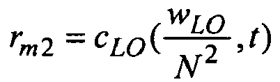
FIG. 5 that the output offrequency divider 514b may be directly coupled to thedown conversion stage 506 and may not be mixed beforehand in theLO mixer 520. Similarly, it may be observed that the output of thefrequency divider 514a may not be coupled to theLO mixer 520 or a down conversion stage, in this embodiment of the invention. Instead, the output offrequency divider 514a may be used as the input to thefrequency divider 514b. - The output of the
frequency divider 514c may be communicatively coupled to an input of themultiplier 510e. The second input of themultiplier 510e may be coupled to the output of thefilter 512d. Hence, the output of themultiplier 510e in the LO mixer may be described by the following relationship:
- By retaining the lower frequency component from the output signal of 510e in the
filter 512e, the output signal of thefilter 512e may be given by the following relationship:
- In the
down conversion stage 504, the output signal r 1 may be given by the following relationship:
where thefilter 512a may be chosen to retain the lower frequency component and r 0 = s(t)cos(w 0 t). z may be the amplification factor introduced byamplifier 502, similar to the description forFIG. 2 . Correspondingly, the output of thedown conversion stage 506 may be given by the following relationship:
where thefilter 512b may have retained the lower frequency component. The output of thedown conversion stage 508 may be given by the following relationship:
Hence, as described above, the output signal r 3 that may be generated by the down conversion stages, may be frequency translated by a factor of 4.125. By appropriately choosing the number of frequency dividers in thefractional LO cascade 530 and suitably combining the outputs of the frequency dividers in theLO mixer 520, an arbitrary down conversion (frequency translation) factor may be achieved. In various embodiments of the invention, a similar approach may be used for a modulator by appropriate filtering in the conversion stages 504, 506 and 508, as described above and with respect toFIG. 2 . - In accordance with an embodiment of the invention, a method and system for a distributed transceiver for high frequency applications may comprise generating a second signal from a first signal for example rK , by frequency-translating the first signal, for example r 0, via a plurality of conversion stages, as illustrated in
FIG.2 ,FIG. 3 andFIG. 5 . Each of the plurality of conversion stages, for example conversion stages 204, 206 and 208, may frequency-translate a corresponding input signal by a local oscillator frequency or by a fraction of said local oscillator frequency, as described forFIG. 2 . The first signal may be the corresponding input signal to an initial stage of a the plurality of conversion stages, an output signal of a previous one of the plurality of conversion stages may be the corresponding input signal to a subsequent one of the plurality of conversion stages, and the second signal may be an output signal of a final stage of the plurality of conversion stages. - The plurality of conversion stages may be communicatively coupled in a cascade configuration, as illustrated in
FIG. 5 . The first signal may be a radio frequency signal or an intermediate frequency signal and the second signal may be a baseband signal. The first signal may be a radio frequency signal or a baseband signal and the second signal may be an intermediate frequency signal. The first signal may be a baseband signal or an intermediate frequency signal and the second signal may be a radio frequency signal, as described forFIG. 2 . The local oscillator frequency, for example wLO . may be associated with a local oscillator signal, for example cLO and the fraction of the local oscillator frequency, for example wLO lN, may be associated with a fractional local oscillator signal, for example c LO/N . The fractional local oscillator signal may be generated from the local oscillator cLO signal by using one or more frequency dividers, for example 514a/b/c. Mixing the local oscillator and/or one or more mixing signals may generate the fractional local oscillator signal, as illustrated inFIG. 2 , for example. The one or more mixing signals may be generated by dividing the local oscillator signal via one or more frequency dividers. The local oscillator may be a sinusoidal signal with a frequency equal to the local oscillator frequency. - Another embodiment of the invention may provide a machine-readable storage, having stored thereon, a computer program having at least one code section executable by a machine, thereby causing the machine to perform the steps as described above for a method and system for a distributed transceiver for high frequency applications.
- Accordingly, the present invention may be realized in hardware, software, or a combination of hardware and software. The present invention may be realized in a centralized fashion in at least one computer system, or in a distributed fashion where different elements are spread across several interconnected computer systems. Any kind of computer system or other apparatus adapted for carrying out the methods described herein is suited. A typical combination of hardware and software may be a general-purpose computer system with a computer program that, when being loaded and executed, controls the computer system such that it carries out the methods described herein.
- The present invention may also be embedded in a computer program product, which comprises all the features enabling the implementation of the methods described herein, and which when loaded in a computer system is able to carry out these methods. Computer program in the present context means any expression, in any language, code or notation, of a set of instructions intended to cause a system having an information processing capability to perform a particular function either directly or after either or both of the following: a) conversion to another language, code or notation; b) reproduction in a different material form.
- While the present invention has been described with reference to certain embodiments, it will be understood by those skilled in the art that various changes may be made and equivalents may be substituted without departing from the scope of the present invention. In addition, many modifications may be made to adapt a particular situation or material to the teachings of the present invention without departing from its scope. Therefore, it is intended that the present invention not be limited to the particular embodiment disclosed, but that the present invention will include all embodiments falling within the scope of the appended claims.
Claims (10)
- A method for processing communication signals, the method comprising:generating a second signal from a first signal by:frequency-translating said first signal via a plurality of conversion stages, wherein:each of said plurality of conversion stages frequency-translates a corresponding input signal by a local oscillator frequency or by a fraction of said local oscillator frequency; andsaid first signal is said corresponding input signal to an initial stage of a said plurality of conversion stages, an output signal of a previous one of said plurality of conversion stages is said corresponding input signal to a subsequent one of said plurality of conversion stages, and said second signal is an output signal of a final stage of said plurality of conversion stages.
- The method according to claim 1, wherein said plurality of conversion stages are communicatively coupled in a cascade configuration.
- The method according to claim 1, wherein said first signal is a radio frequency signal or an intermediate frequency signal and said second signal is a baseband signal.
- The method according to claim 1, wherein said first signal is a radio frequency signal or a baseband signal and said second signal is an intermediate frequency signal.
- The method according to claim 1, wherein said first signal is a baseband signal or an intermediate frequency signal and said second signal is a radio frequency signal.
- The method according to claim 1, wherein said local oscillator frequency is associated with a local oscillator signal and said fraction of said local oscillator frequency is associated with a fractional local oscillator signal
- A system for processing communication signals, the system comprising:one or more circuits, said one or more circuits enabled to generate a second signal from a first signal by:frequency-translating said first signal via a plurality of conversion stages, wherein:each of said plurality of conversion stages frequency-translates a corresponding input signal by a local oscillator frequency or by a fraction of said local oscillator frequency; andsaid first signal is said corresponding input signal to an initial stage of a said plurality of conversion stages, an output signal of a previous one of said plurality of conversion stages is said corresponding input signal to a subsequent one of said plurality of conversion stages, and said second signal is an output signal of a final stage of said plurality of conversion stages.
- The system according to claim 7, wherein said plurality of conversion stages are communicatively coupled in a cascade configuration.
- The system according to claim 7, wherein said first signal is a radio frequency signal or an intermediate frequency signal and said second signal is a baseband signal.
- The system according to claim 7, wherein said first signal is a radio frequency signal or a baseband signal and said second signal is an intermediate frequency signal.
Applications Claiming Priority (1)
| Application Number | Priority Date | Filing Date | Title |
|---|---|---|---|
| US11/860,207 US8027656B2 (en) | 2007-09-24 | 2007-09-24 | Method and system for a distributed transceiver for high frequency applications |
Publications (3)
| Publication Number | Publication Date |
|---|---|
| EP2040386A2 true EP2040386A2 (en) | 2009-03-25 |
| EP2040386A3 EP2040386A3 (en) | 2013-09-11 |
| EP2040386B1 EP2040386B1 (en) | 2017-08-09 |
Family
ID=40086411
Family Applications (1)
| Application Number | Title | Priority Date | Filing Date |
|---|---|---|---|
| EP08014992.5A Ceased EP2040386B1 (en) | 2007-09-24 | 2008-08-25 | Method and system for a distributed transceiver for high frequency applications |
Country Status (5)
| Country | Link |
|---|---|
| US (1) | US8027656B2 (en) |
| EP (1) | EP2040386B1 (en) |
| KR (1) | KR101000992B1 (en) |
| CN (1) | CN101399808B (en) |
| TW (1) | TWI426703B (en) |
Families Citing this family (47)
| Publication number | Priority date | Publication date | Assignee | Title |
|---|---|---|---|---|
| US8873585B2 (en) | 2006-12-19 | 2014-10-28 | Corning Optical Communications Wireless Ltd | Distributed antenna system for MIMO technologies |
| US8019313B2 (en) * | 2007-09-24 | 2011-09-13 | Broadcom Corporation | Method and system for distributed transceivers based on notch filters and passive mixers |
| WO2009081376A2 (en) | 2007-12-20 | 2009-07-02 | Mobileaccess Networks Ltd. | Extending outdoor location based services and applications into enclosed areas |
| EP2344915A4 (en) | 2008-10-09 | 2015-01-21 | Corning Cable Sys Llc | OPTICAL FIBER TERMINAL HAVING AN ADAPTER PANEL HAVING BOTH INPUT AND OUTPUT FIBERS FROM AN OPTICAL DIVIDER |
| AU2010210766A1 (en) | 2009-02-03 | 2011-09-15 | Corning Cable Systems Llc | Optical fiber-based distributed antenna systems, components, and related methods for monitoring and configuring thereof |
| US9673904B2 (en) | 2009-02-03 | 2017-06-06 | Corning Optical Communications LLC | Optical fiber-based distributed antenna systems, components, and related methods for calibration thereof |
| WO2010091004A1 (en) | 2009-02-03 | 2010-08-12 | Corning Cable Systems Llc | Optical fiber-based distributed antenna systems, components, and related methods for calibration thereof |
| US9590733B2 (en) | 2009-07-24 | 2017-03-07 | Corning Optical Communications LLC | Location tracking using fiber optic array cables and related systems and methods |
| US8280259B2 (en) | 2009-11-13 | 2012-10-02 | Corning Cable Systems Llc | Radio-over-fiber (RoF) system for protocol-independent wired and/or wireless communication |
| US8275265B2 (en) | 2010-02-15 | 2012-09-25 | Corning Cable Systems Llc | Dynamic cell bonding (DCB) for radio-over-fiber (RoF)-based networks and communication systems and related methods |
| CN102845001B (en) | 2010-03-31 | 2016-07-06 | 康宁光缆系统有限责任公司 | Based on positioning service in the distributed communication assembly of optical fiber and system and associated method |
| WO2011136558A2 (en) * | 2010-04-28 | 2011-11-03 | 엘지전자 주식회사 | Method and apparatus for performing random access procedures in a wireless communication system |
| US8570914B2 (en) | 2010-08-09 | 2013-10-29 | Corning Cable Systems Llc | Apparatuses, systems, and methods for determining location of a mobile device(s) in a distributed antenna system(s) |
| US9252874B2 (en) | 2010-10-13 | 2016-02-02 | Ccs Technology, Inc | Power management for remote antenna units in distributed antenna systems |
| US9547145B2 (en) | 2010-10-19 | 2017-01-17 | Corning Optical Communications LLC | Local convergence point for multiple dwelling unit fiber optic distribution network |
| CN103609146B (en) | 2011-04-29 | 2017-05-31 | 康宁光缆系统有限责任公司 | Systems, methods and apparatus for increasing radio frequency (RF) power in a distributed antenna system |
| WO2012148938A1 (en) | 2011-04-29 | 2012-11-01 | Corning Cable Systems Llc | Determining propagation delay of communications in distributed antenna systems, and related components, systems and methods |
| US9219546B2 (en) | 2011-12-12 | 2015-12-22 | Corning Optical Communications LLC | Extremely high frequency (EHF) distributed antenna systems, and related components and methods |
| US10110307B2 (en) | 2012-03-02 | 2018-10-23 | Corning Optical Communications LLC | Optical network units (ONUs) for high bandwidth connectivity, and related components and methods |
| EP2832012A1 (en) | 2012-03-30 | 2015-02-04 | Corning Optical Communications LLC | Reducing location-dependent interference in distributed antenna systems operating in multiple-input, multiple-output (mimo) configuration, and related components, systems, and methods |
| US9781553B2 (en) | 2012-04-24 | 2017-10-03 | Corning Optical Communications LLC | Location based services in a distributed communication system, and related components and methods |
| WO2013162988A1 (en) | 2012-04-25 | 2013-10-31 | Corning Cable Systems Llc | Distributed antenna system architectures |
| EP2883416A1 (en) | 2012-08-07 | 2015-06-17 | Corning Optical Communications Wireless Ltd. | Distribution of time-division multiplexed (tdm) management services in a distributed antenna system, and related components, systems, and methods |
| US9455784B2 (en) | 2012-10-31 | 2016-09-27 | Corning Optical Communications Wireless Ltd | Deployable wireless infrastructures and methods of deploying wireless infrastructures |
| EP2926466A1 (en) | 2012-11-29 | 2015-10-07 | Corning Optical Communications LLC | HYBRID INTRA-CELL / INTER-CELL REMOTE UNIT ANTENNA BONDING IN MULTIPLE-INPUT, MULTIPLE-OUTPUT (MIMO) DISTRIBUTED ANTENNA SYSTEMS (DASs) |
| US9647758B2 (en) | 2012-11-30 | 2017-05-09 | Corning Optical Communications Wireless Ltd | Cabling connectivity monitoring and verification |
| US9158864B2 (en) | 2012-12-21 | 2015-10-13 | Corning Optical Communications Wireless Ltd | Systems, methods, and devices for documenting a location of installed equipment |
| WO2014199380A1 (en) | 2013-06-12 | 2014-12-18 | Corning Optical Communications Wireless, Ltd. | Time-division duplexing (tdd) in distributed communications systems, including distributed antenna systems (dass) |
| CN105452951B (en) | 2013-06-12 | 2018-10-19 | 康宁光电通信无线公司 | Voltage type optical directional coupler |
| US9247543B2 (en) | 2013-07-23 | 2016-01-26 | Corning Optical Communications Wireless Ltd | Monitoring non-supported wireless spectrum within coverage areas of distributed antenna systems (DASs) |
| US9661781B2 (en) | 2013-07-31 | 2017-05-23 | Corning Optical Communications Wireless Ltd | Remote units for distributed communication systems and related installation methods and apparatuses |
| US9385810B2 (en) | 2013-09-30 | 2016-07-05 | Corning Optical Communications Wireless Ltd | Connection mapping in distributed communication systems |
| US9178635B2 (en) | 2014-01-03 | 2015-11-03 | Corning Optical Communications Wireless Ltd | Separation of communication signal sub-bands in distributed antenna systems (DASs) to reduce interference |
| US9775123B2 (en) | 2014-03-28 | 2017-09-26 | Corning Optical Communications Wireless Ltd. | Individualized gain control of uplink paths in remote units in a distributed antenna system (DAS) based on individual remote unit contribution to combined uplink power |
| US9357551B2 (en) | 2014-05-30 | 2016-05-31 | Corning Optical Communications Wireless Ltd | Systems and methods for simultaneous sampling of serial digital data streams from multiple analog-to-digital converters (ADCS), including in distributed antenna systems |
| US9525472B2 (en) | 2014-07-30 | 2016-12-20 | Corning Incorporated | Reducing location-dependent destructive interference in distributed antenna systems (DASS) operating in multiple-input, multiple-output (MIMO) configuration, and related components, systems, and methods |
| US9730228B2 (en) | 2014-08-29 | 2017-08-08 | Corning Optical Communications Wireless Ltd | Individualized gain control of remote uplink band paths in a remote unit in a distributed antenna system (DAS), based on combined uplink power level in the remote unit |
| US9602210B2 (en) | 2014-09-24 | 2017-03-21 | Corning Optical Communications Wireless Ltd | Flexible head-end chassis supporting automatic identification and interconnection of radio interface modules and optical interface modules in an optical fiber-based distributed antenna system (DAS) |
| US9420542B2 (en) | 2014-09-25 | 2016-08-16 | Corning Optical Communications Wireless Ltd | System-wide uplink band gain control in a distributed antenna system (DAS), based on per band gain control of remote uplink paths in remote units |
| US9729267B2 (en) | 2014-12-11 | 2017-08-08 | Corning Optical Communications Wireless Ltd | Multiplexing two separate optical links with the same wavelength using asymmetric combining and splitting |
| US20160249365A1 (en) | 2015-02-19 | 2016-08-25 | Corning Optical Communications Wireless Ltd. | Offsetting unwanted downlink interference signals in an uplink path in a distributed antenna system (das) |
| US9681313B2 (en) | 2015-04-15 | 2017-06-13 | Corning Optical Communications Wireless Ltd | Optimizing remote antenna unit performance using an alternative data channel |
| US9948349B2 (en) | 2015-07-17 | 2018-04-17 | Corning Optical Communications Wireless Ltd | IOT automation and data collection system |
| US10560214B2 (en) | 2015-09-28 | 2020-02-11 | Corning Optical Communications LLC | Downlink and uplink communication path switching in a time-division duplex (TDD) distributed antenna system (DAS) |
| US9648580B1 (en) | 2016-03-23 | 2017-05-09 | Corning Optical Communications Wireless Ltd | Identifying remote units in a wireless distribution system (WDS) based on assigned unique temporal delay patterns |
| US10236924B2 (en) | 2016-03-31 | 2019-03-19 | Corning Optical Communications Wireless Ltd | Reducing out-of-channel noise in a wireless distribution system (WDS) |
| US11320179B2 (en) | 2019-09-26 | 2022-05-03 | Randy Prohaska | Fluid or gas cooling and/or condensing apparatus, system and method |
Citations (4)
| Publication number | Priority date | Publication date | Assignee | Title |
|---|---|---|---|---|
| US4580289A (en) | 1981-12-30 | 1986-04-01 | Motorola, Inc. | Fully integratable superheterodyne radio receiver utilizing tunable filters |
| US5108334A (en) | 1989-06-01 | 1992-04-28 | Trimble Navigation, Ltd. | Dual down conversion GPS receiver with single local oscillator |
| US6282413B1 (en) | 1997-03-12 | 2001-08-28 | U.S. Philips Corporation | Multistaged frequency conversion with single local oscillator |
| US20070026832A1 (en) | 2005-07-27 | 2007-02-01 | Casio Computer Co., Ltd. | Radio wave receiving apparatus, radio wave receiving circuit and radio wave timepiece |
Family Cites Families (8)
| Publication number | Priority date | Publication date | Assignee | Title |
|---|---|---|---|---|
| US4453137A (en) * | 1982-02-05 | 1984-06-05 | The United States Of America As Represented By The Secretary Of The Army | Signal processor for plural frequency detection and tracking over predetermined range of frequencies |
| GB9617423D0 (en) * | 1995-10-11 | 1996-10-02 | Philips Electronics Nv | Receiver circuit |
| JP2003152561A (en) * | 2001-11-08 | 2003-05-23 | Alps Electric Co Ltd | Frequency conversion circuit |
| US7233774B2 (en) | 2003-01-30 | 2007-06-19 | Broadcom Corporation | RF transceiver with compact stacked mixer design for multiple frequency conversion |
| US20040205827A1 (en) | 2003-04-14 | 2004-10-14 | Krone Andrew W. | Multi-stage channel select filter and associated method |
| GB2402564B (en) * | 2003-06-07 | 2006-04-05 | Zarlink Semiconductor Ltd | Multiple conversion tuner |
| US7395290B2 (en) * | 2004-06-04 | 2008-07-01 | Agilent Technologies, Inc. | Digital filter and method thereof using frequency translations |
| US8019313B2 (en) * | 2007-09-24 | 2011-09-13 | Broadcom Corporation | Method and system for distributed transceivers based on notch filters and passive mixers |
-
2007
- 2007-09-24 US US11/860,207 patent/US8027656B2/en active Active
-
2008
- 2008-08-25 EP EP08014992.5A patent/EP2040386B1/en not_active Ceased
- 2008-09-22 KR KR1020080092711A patent/KR101000992B1/en active Active
- 2008-09-22 CN CN200810168439XA patent/CN101399808B/en active Active
- 2008-09-24 TW TW097136683A patent/TWI426703B/en not_active IP Right Cessation
Patent Citations (4)
| Publication number | Priority date | Publication date | Assignee | Title |
|---|---|---|---|---|
| US4580289A (en) | 1981-12-30 | 1986-04-01 | Motorola, Inc. | Fully integratable superheterodyne radio receiver utilizing tunable filters |
| US5108334A (en) | 1989-06-01 | 1992-04-28 | Trimble Navigation, Ltd. | Dual down conversion GPS receiver with single local oscillator |
| US6282413B1 (en) | 1997-03-12 | 2001-08-28 | U.S. Philips Corporation | Multistaged frequency conversion with single local oscillator |
| US20070026832A1 (en) | 2005-07-27 | 2007-02-01 | Casio Computer Co., Ltd. | Radio wave receiving apparatus, radio wave receiving circuit and radio wave timepiece |
Also Published As
| Publication number | Publication date |
|---|---|
| EP2040386B1 (en) | 2017-08-09 |
| HK1130971A1 (en) | 2010-01-08 |
| US8027656B2 (en) | 2011-09-27 |
| TWI426703B (en) | 2014-02-11 |
| US20090081981A1 (en) | 2009-03-26 |
| KR101000992B1 (en) | 2010-12-13 |
| TW200935723A (en) | 2009-08-16 |
| EP2040386A3 (en) | 2013-09-11 |
| KR20090031651A (en) | 2009-03-27 |
| CN101399808B (en) | 2013-07-10 |
| CN101399808A (en) | 2009-04-01 |
Similar Documents
| Publication | Publication Date | Title |
|---|---|---|
| EP2040386B1 (en) | Method and system for a distributed transceiver for high frequency applications | |
| US8036626B2 (en) | Method and system for a distributed transceiver with DDFS channel selection | |
| US12199927B2 (en) | Single local oscillator in a multi-band frequency division duplex transceiver | |
| TW591898B (en) | Multistage modulation architecture and method in a radio frequency transmitter | |
| Levinger et al. | High-performance E-band transceiver chipset for point-to-point communication in SiGe BiCMOS technology | |
| US7570919B2 (en) | Transmitter, receiver, and radio communications system and method | |
| US8208881B2 (en) | Radio frequency receiver and radio frequency transmitter | |
| US20080233892A1 (en) | Method and system for an integrated vco and local oscillator architecture for an integrated fm transmitter and fm receiver | |
| KR20080059261A (en) | Single-Chip SMS / EDV Transceiver Structure with Closed-Loop Power Control | |
| CN1140941A (en) | Transceiver device with single phase locked loop and method thereof | |
| US20070099582A1 (en) | Method and apparatus for signal demodulation and transmission | |
| US8019313B2 (en) | Method and system for distributed transceivers based on notch filters and passive mixers | |
| US20080125060A1 (en) | Radio Frequency Transceiver | |
| US8514997B2 (en) | Method and system for a receiver with undersampling mixing using multiple clock phases | |
| US20090081983A1 (en) | Method and system for a distributed quadrature transceiver for high frequency applications | |
| US20120274367A1 (en) | Front-End Transceiver | |
| US20090081954A1 (en) | Method and system for a distributed quadrature transceiver using phase shifting | |
| JP2006191409A (en) | Transmitting/receiving circuit, transmitting circuit and receiving circuit | |
| US20090080502A1 (en) | Method and system for distributed transceivers based on rf quadrature and lo quadrature filtering for high frequency applications | |
| US8830880B2 (en) | Clock signal leakage cancellation in wireless systems | |
| US8768282B2 (en) | Apparatus generating subcarrier for transmission between ultra-high frequency channels and method generating of the same | |
| HK1130971B (en) | A method and system for processing communication signal | |
| Yishay et al. | High-performance 81–86 GHz transceiver chipset for Point-to-Point communication in SiGe BiCMOS technology | |
| DE102020100844A1 (en) | Single local oscillator in a multiband frequency duplex transceiver | |
| EP1881608A1 (en) | Radio frequency transceiver |
Legal Events
| Date | Code | Title | Description |
|---|---|---|---|
| PUAI | Public reference made under article 153(3) epc to a published international application that has entered the european phase |
Free format text: ORIGINAL CODE: 0009012 |
|
| 17P | Request for examination filed |
Effective date: 20080825 |
|
| AK | Designated contracting states |
Kind code of ref document: A2 Designated state(s): AT BE BG CH CY CZ DE DK EE ES FI FR GB GR HR HU IE IS IT LI LT LU LV MC MT NL NO PL PT RO SE SI SK TR |
|
| AX | Request for extension of the european patent |
Extension state: AL BA MK RS |
|
| PUAL | Search report despatched |
Free format text: ORIGINAL CODE: 0009013 |
|
| AK | Designated contracting states |
Kind code of ref document: A3 Designated state(s): AT BE BG CH CY CZ DE DK EE ES FI FR GB GR HR HU IE IS IT LI LT LU LV MC MT NL NO PL PT RO SE SI SK TR |
|
| AX | Request for extension of the european patent |
Extension state: AL BA MK RS |
|
| RIC1 | Information provided on ipc code assigned before grant |
Ipc: H04B 1/00 20060101ALN20130807BHEP Ipc: H04B 1/40 20060101AFI20130807BHEP Ipc: H04B 1/16 20060101ALN20130807BHEP Ipc: H04B 1/04 20060101ALN20130807BHEP Ipc: H03D 7/16 20060101ALI20130807BHEP |
|
| 17Q | First examination report despatched |
Effective date: 20130827 |
|
| RBV | Designated contracting states (corrected) |
Designated state(s): AT BE BG CH CY CZ DE DK EE ES FI FR GB GR HR HU IE IS IT LI LT LU LV MC MT NL NO PL PT RO SE SI SK TR |
|
| AKX | Designation fees paid |
Designated state(s): DE GB |
|
| STAA | Information on the status of an ep patent application or granted ep patent |
Free format text: STATUS: EXAMINATION IS IN PROGRESS |
|
| GRAP | Despatch of communication of intention to grant a patent |
Free format text: ORIGINAL CODE: EPIDOSNIGR1 |
|
| STAA | Information on the status of an ep patent application or granted ep patent |
Free format text: STATUS: GRANT OF PATENT IS INTENDED |
|
| RIC1 | Information provided on ipc code assigned before grant |
Ipc: H04B 1/00 20060101ALN20170221BHEP Ipc: H04B 1/408 20150101ALI20170221BHEP Ipc: H03D 7/16 20060101ALI20170221BHEP Ipc: H04B 1/16 20060101ALN20170221BHEP Ipc: H04B 1/04 20060101ALN20170221BHEP Ipc: H04B 1/40 20150101AFI20170221BHEP |
|
| INTG | Intention to grant announced |
Effective date: 20170310 |
|
| RAP1 | Party data changed (applicant data changed or rights of an application transferred) |
Owner name: AVAGO TECHNOLOGIES GENERAL IP (SINGAPORE) PTE. LTD |
|
| GRAS | Grant fee paid |
Free format text: ORIGINAL CODE: EPIDOSNIGR3 |
|
| GRAA | (expected) grant |
Free format text: ORIGINAL CODE: 0009210 |
|
| STAA | Information on the status of an ep patent application or granted ep patent |
Free format text: STATUS: THE PATENT HAS BEEN GRANTED |
|
| AK | Designated contracting states |
Kind code of ref document: B1 Designated state(s): DE GB |
|
| REG | Reference to a national code |
Ref country code: GB Ref legal event code: FG4D |
|
| REG | Reference to a national code |
Ref country code: DE Ref legal event code: R096 Ref document number: 602008051480 Country of ref document: DE |
|
| REG | Reference to a national code |
Ref country code: DE Ref legal event code: R119 Ref document number: 602008051480 Country of ref document: DE |
|
| PLBE | No opposition filed within time limit |
Free format text: ORIGINAL CODE: 0009261 |
|
| STAA | Information on the status of an ep patent application or granted ep patent |
Free format text: STATUS: NO OPPOSITION FILED WITHIN TIME LIMIT |
|
| 26N | No opposition filed |
Effective date: 20180511 |
|
| GBPC | Gb: european patent ceased through non-payment of renewal fee |
Effective date: 20171109 |
|
| PG25 | Lapsed in a contracting state [announced via postgrant information from national office to epo] |
Ref country code: DE Free format text: LAPSE BECAUSE OF NON-PAYMENT OF DUE FEES Effective date: 20180301 |
|
| PG25 | Lapsed in a contracting state [announced via postgrant information from national office to epo] |
Ref country code: GB Free format text: LAPSE BECAUSE OF NON-PAYMENT OF DUE FEES Effective date: 20171109 |