EP2040112A1 - Liquid crystal module - Google Patents
Liquid crystal module Download PDFInfo
- Publication number
- EP2040112A1 EP2040112A1 EP08016363A EP08016363A EP2040112A1 EP 2040112 A1 EP2040112 A1 EP 2040112A1 EP 08016363 A EP08016363 A EP 08016363A EP 08016363 A EP08016363 A EP 08016363A EP 2040112 A1 EP2040112 A1 EP 2040112A1
- Authority
- EP
- European Patent Office
- Prior art keywords
- rear frame
- liquid crystal
- lamp sockets
- cold cathode
- crystal module
- Prior art date
- Legal status (The legal status is an assumption and is not a legal conclusion. Google has not performed a legal analysis and makes no representation as to the accuracy of the status listed.)
- Withdrawn
Links
- 239000004973 liquid crystal related substance Substances 0.000 title claims abstract description 55
- 230000003287 optical effect Effects 0.000 claims abstract description 7
- 238000003780 insertion Methods 0.000 claims description 6
- 230000037431 insertion Effects 0.000 claims description 6
- WABPQHHGFIMREM-UHFFFAOYSA-N lead(0) Chemical compound [Pb] WABPQHHGFIMREM-UHFFFAOYSA-N 0.000 description 5
- 229920002379 silicone rubber Polymers 0.000 description 4
- 239000004945 silicone rubber Substances 0.000 description 4
- 125000006850 spacer group Chemical group 0.000 description 4
- 239000004033 plastic Substances 0.000 description 3
- 230000002093 peripheral effect Effects 0.000 description 2
- 210000002858 crystal cell Anatomy 0.000 description 1
- 230000009977 dual effect Effects 0.000 description 1
- 229920001971 elastomer Polymers 0.000 description 1
- 239000000463 material Substances 0.000 description 1
- 239000002184 metal Substances 0.000 description 1
- 238000012986 modification Methods 0.000 description 1
- 230000004048 modification Effects 0.000 description 1
- 238000005476 soldering Methods 0.000 description 1
Images




Classifications
-
- G—PHYSICS
- G02—OPTICS
- G02F—OPTICAL DEVICES OR ARRANGEMENTS FOR THE CONTROL OF LIGHT BY MODIFICATION OF THE OPTICAL PROPERTIES OF THE MEDIA OF THE ELEMENTS INVOLVED THEREIN; NON-LINEAR OPTICS; FREQUENCY-CHANGING OF LIGHT; OPTICAL LOGIC ELEMENTS; OPTICAL ANALOGUE/DIGITAL CONVERTERS
- G02F1/00—Devices or arrangements for the control of the intensity, colour, phase, polarisation or direction of light arriving from an independent light source, e.g. switching, gating or modulating; Non-linear optics
- G02F1/01—Devices or arrangements for the control of the intensity, colour, phase, polarisation or direction of light arriving from an independent light source, e.g. switching, gating or modulating; Non-linear optics for the control of the intensity, phase, polarisation or colour
- G02F1/13—Devices or arrangements for the control of the intensity, colour, phase, polarisation or direction of light arriving from an independent light source, e.g. switching, gating or modulating; Non-linear optics for the control of the intensity, phase, polarisation or colour based on liquid crystals, e.g. single liquid crystal display cells
- G02F1/133—Constructional arrangements; Operation of liquid crystal cells; Circuit arrangements
- G02F1/1333—Constructional arrangements; Manufacturing methods
- G02F1/1335—Structural association of cells with optical devices, e.g. polarisers or reflectors
- G02F1/1336—Illuminating devices
- G02F1/133602—Direct backlight
- G02F1/133608—Direct backlight including particular frames or supporting means
-
- F—MECHANICAL ENGINEERING; LIGHTING; HEATING; WEAPONS; BLASTING
- F21—LIGHTING
- F21V—FUNCTIONAL FEATURES OR DETAILS OF LIGHTING DEVICES OR SYSTEMS THEREOF; STRUCTURAL COMBINATIONS OF LIGHTING DEVICES WITH OTHER ARTICLES, NOT OTHERWISE PROVIDED FOR
- F21V19/00—Fastening of light sources or lamp holders
- F21V19/0075—Fastening of light sources or lamp holders of tubular light sources, e.g. ring-shaped fluorescent light sources
- F21V19/0095—Fastening of light sources or lamp holders of tubular light sources, e.g. ring-shaped fluorescent light sources of U-shaped tubular light sources, e.g. compact fluorescent tubes
-
- F—MECHANICAL ENGINEERING; LIGHTING; HEATING; WEAPONS; BLASTING
- F21—LIGHTING
- F21V—FUNCTIONAL FEATURES OR DETAILS OF LIGHTING DEVICES OR SYSTEMS THEREOF; STRUCTURAL COMBINATIONS OF LIGHTING DEVICES WITH OTHER ARTICLES, NOT OTHERWISE PROVIDED FOR
- F21V15/00—Protecting lighting devices from damage
- F21V15/04—Resilient mountings, e.g. shock absorbers
-
- F—MECHANICAL ENGINEERING; LIGHTING; HEATING; WEAPONS; BLASTING
- F21—LIGHTING
- F21V—FUNCTIONAL FEATURES OR DETAILS OF LIGHTING DEVICES OR SYSTEMS THEREOF; STRUCTURAL COMBINATIONS OF LIGHTING DEVICES WITH OTHER ARTICLES, NOT OTHERWISE PROVIDED FOR
- F21V19/00—Fastening of light sources or lamp holders
- F21V19/0075—Fastening of light sources or lamp holders of tubular light sources, e.g. ring-shaped fluorescent light sources
- F21V19/008—Fastening of light sources or lamp holders of tubular light sources, e.g. ring-shaped fluorescent light sources of straight tubular light sources, e.g. straight fluorescent tubes, soffit lamps
- F21V19/0085—Fastening of light sources or lamp holders of tubular light sources, e.g. ring-shaped fluorescent light sources of straight tubular light sources, e.g. straight fluorescent tubes, soffit lamps at least one conductive element acting as a support means, e.g. resilient contact blades, piston-like contact
-
- F—MECHANICAL ENGINEERING; LIGHTING; HEATING; WEAPONS; BLASTING
- F21—LIGHTING
- F21V—FUNCTIONAL FEATURES OR DETAILS OF LIGHTING DEVICES OR SYSTEMS THEREOF; STRUCTURAL COMBINATIONS OF LIGHTING DEVICES WITH OTHER ARTICLES, NOT OTHERWISE PROVIDED FOR
- F21V19/00—Fastening of light sources or lamp holders
- F21V19/0075—Fastening of light sources or lamp holders of tubular light sources, e.g. ring-shaped fluorescent light sources
- F21V19/008—Fastening of light sources or lamp holders of tubular light sources, e.g. ring-shaped fluorescent light sources of straight tubular light sources, e.g. straight fluorescent tubes, soffit lamps
- F21V19/009—Fastening of light sources or lamp holders of tubular light sources, e.g. ring-shaped fluorescent light sources of straight tubular light sources, e.g. straight fluorescent tubes, soffit lamps the support means engaging the vessel of the source
-
- G—PHYSICS
- G02—OPTICS
- G02F—OPTICAL DEVICES OR ARRANGEMENTS FOR THE CONTROL OF LIGHT BY MODIFICATION OF THE OPTICAL PROPERTIES OF THE MEDIA OF THE ELEMENTS INVOLVED THEREIN; NON-LINEAR OPTICS; FREQUENCY-CHANGING OF LIGHT; OPTICAL LOGIC ELEMENTS; OPTICAL ANALOGUE/DIGITAL CONVERTERS
- G02F1/00—Devices or arrangements for the control of the intensity, colour, phase, polarisation or direction of light arriving from an independent light source, e.g. switching, gating or modulating; Non-linear optics
- G02F1/01—Devices or arrangements for the control of the intensity, colour, phase, polarisation or direction of light arriving from an independent light source, e.g. switching, gating or modulating; Non-linear optics for the control of the intensity, phase, polarisation or colour
- G02F1/13—Devices or arrangements for the control of the intensity, colour, phase, polarisation or direction of light arriving from an independent light source, e.g. switching, gating or modulating; Non-linear optics for the control of the intensity, phase, polarisation or colour based on liquid crystals, e.g. single liquid crystal display cells
- G02F1/133—Constructional arrangements; Operation of liquid crystal cells; Circuit arrangements
- G02F1/1333—Constructional arrangements; Manufacturing methods
- G02F1/133308—Support structures for LCD panels, e.g. frames or bezels
- G02F1/133317—Intermediate frames, e.g. between backlight housing and front frame
-
- G—PHYSICS
- G02—OPTICS
- G02F—OPTICAL DEVICES OR ARRANGEMENTS FOR THE CONTROL OF LIGHT BY MODIFICATION OF THE OPTICAL PROPERTIES OF THE MEDIA OF THE ELEMENTS INVOLVED THEREIN; NON-LINEAR OPTICS; FREQUENCY-CHANGING OF LIGHT; OPTICAL LOGIC ELEMENTS; OPTICAL ANALOGUE/DIGITAL CONVERTERS
- G02F1/00—Devices or arrangements for the control of the intensity, colour, phase, polarisation or direction of light arriving from an independent light source, e.g. switching, gating or modulating; Non-linear optics
- G02F1/01—Devices or arrangements for the control of the intensity, colour, phase, polarisation or direction of light arriving from an independent light source, e.g. switching, gating or modulating; Non-linear optics for the control of the intensity, phase, polarisation or colour
- G02F1/13—Devices or arrangements for the control of the intensity, colour, phase, polarisation or direction of light arriving from an independent light source, e.g. switching, gating or modulating; Non-linear optics for the control of the intensity, phase, polarisation or colour based on liquid crystals, e.g. single liquid crystal display cells
- G02F1/133—Constructional arrangements; Operation of liquid crystal cells; Circuit arrangements
- G02F1/1333—Constructional arrangements; Manufacturing methods
- G02F1/133308—Support structures for LCD panels, e.g. frames or bezels
- G02F1/133328—Segmented frames
-
- G—PHYSICS
- G02—OPTICS
- G02F—OPTICAL DEVICES OR ARRANGEMENTS FOR THE CONTROL OF LIGHT BY MODIFICATION OF THE OPTICAL PROPERTIES OF THE MEDIA OF THE ELEMENTS INVOLVED THEREIN; NON-LINEAR OPTICS; FREQUENCY-CHANGING OF LIGHT; OPTICAL LOGIC ELEMENTS; OPTICAL ANALOGUE/DIGITAL CONVERTERS
- G02F1/00—Devices or arrangements for the control of the intensity, colour, phase, polarisation or direction of light arriving from an independent light source, e.g. switching, gating or modulating; Non-linear optics
- G02F1/01—Devices or arrangements for the control of the intensity, colour, phase, polarisation or direction of light arriving from an independent light source, e.g. switching, gating or modulating; Non-linear optics for the control of the intensity, phase, polarisation or colour
- G02F1/13—Devices or arrangements for the control of the intensity, colour, phase, polarisation or direction of light arriving from an independent light source, e.g. switching, gating or modulating; Non-linear optics for the control of the intensity, phase, polarisation or colour based on liquid crystals, e.g. single liquid crystal display cells
- G02F1/133—Constructional arrangements; Operation of liquid crystal cells; Circuit arrangements
- G02F1/1333—Constructional arrangements; Manufacturing methods
- G02F1/1335—Structural association of cells with optical devices, e.g. polarisers or reflectors
- G02F1/1336—Illuminating devices
- G02F1/133602—Direct backlight
- G02F1/133604—Direct backlight with lamps
Definitions
- the present invention generally relates to a liquid crystal module. More specifically, the present invention relates to a liquid crystal module having a light source fixed to a frame.
- a conventional liquid crystal module having a direct back-lighting system includes a rear frame, a light reflecting sheet, a plurality of cold cathode tubes, an optical sheet, a liquid crystal panel and a bezel.
- the light reflecting sheet is provided inside the rear frame.
- the cold cathode tube is provided over the light reflecting sheet.
- the cold cathode tube is bent in a U shape.
- the optical sheet and the liquid crystal panel are disposed above the cold cathode tube. Edges of the liquid crystal panel are held down from above with the bezel.
- each of the cold cathode tubes is fixed in place with a single, large, common lamp socket.
- the lamp socket is made of silicone rubber.
- Each of the lamp sockets is attached to both ends of each of the U-shaped cold cathode tubes, and fitted into each of groove-shaped openings formed in the rear frame so as to completely block off the groove-shaped openings.
- the groove-shaped openings are formed so that lead wires connected to terminals formed at the both ends of the cold cathode tubes extend through the groove-shaped openings.
- lamp sockets cover both ends of horizontal tube parts of U-shaped light sources.
- the lamp sockets are plugged into pockets formed in a rear frame of the liquid crystal module to fix the light sources (see Japanese Laid-Open Patent Application Publication No. 2006-171167 , for example).
- the spacers disclosed in Japanese Laid-Open Patent Application Publication No. 2006-330162 and the lamp sockets disclosed in Japanese Laid-Open Patent Application Publication No. 2006-171167 are fitted into a box-shaped support frame or pockets provided to an outside of a side wall of the rear frame, and are not fitted into groove-shaped openings formed in the rear frame.
- the present invention is conceived in light of the above-mentioned problems.
- One object of the present invention is to provide a liquid crystal module in which a light source can be accurately positioned and fixed to a rear frame with a simple structure.
- a liquid crystal module includes a rear frame, a light reflecting sheet, a cold cathode tube, an optical sheet, a liquid crystal panel, a pair of lead wires and a pair of lamp sockets.
- the rear frame has an access opening.
- the light reflecting sheet is disposed in an interior of the rear frame.
- the cold cathode tube is disposed above the light reflecting sheet in the interior of the rear frame and having a pair of electric terminals at both end portions of the cold cathode tube.
- the optical sheet and the liquid crystal panel are disposed above the cold cathode tube.
- the pair of lead wires is connected to the electric terminals to form connected portions between the lead wires and the electric terminals.
- the lead wires extend through the access opening of the rear frame from the interior of the rear frame.
- the pair of lamp sockets is fixedly attached to the both end portions of the cold cathode tube and fitted into the access opening of the rear frame to support the cold cathode tube with respect to the rear frame.
- liquid crystal module of the present invention it is possible to provide a liquid crystal module in which a light source can be accurately positioned and fixed to a rear frame with a simple structure
- FIG. 1 is exploded perspective view of a liquid crystal module in accordance with an embodiment of the present invention
- FIG. 2 is a cross sectional view of the liquid crystal module illustrated in FIG. 1 ;
- FIG. 3 is a front elevational view of a rear frame of the liquid crystal module illustrated in FIG. 1 ;
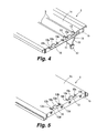
- FIG. 4 is a partial perspective view illustrating a front side of the rear frame
- FIG. 5 is a partial perspective view illustrating a rear side of the rear frame
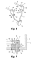
- FIG. 6 is a perspective view of a lamp socket
- FIG. 7 is a cross sectional view of an attachment between the lamp socket and the rear frame taken along ling VII-VII shown in FIG. 3 ;
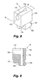
- FIG. 8 is a perspective view of the lamp socket
- FIG. 9 a cross sectional view of the lamp socket taken along line IX-IX shown in FIG. 8 ;
- FIG. 10 is a front plan view of the lamp socket illustrated in FIG. 8 ;
- FIG. 11 is a top plan view of the lamp socket illustrated in FIG. 8 ;
- FIG. 12 is a right side plan view of the lamp socket illustrated in FIG. 8 ;
- FIG. 13 is a bottom plan view of the lamp socket illustrated in FIG. 8 .
- a liquid crystal module includes a rear frame 1, a light reflecting sheet 2, a plurality of (two) cold cathode tubes 3, a pair of left and right lamp frames 4, a light diffusing sheet 5, a prism sheet 6, two L-shaped plastic frames 7, a liquid crystal panel (liquid crystal cell) 8 and a bezel 9.
- the liquid crystal module is installed into a television set or a liquid crystal display device to display image.
- the rear frame 1 has a left side plate 1a, a right side plate 1b and a bottom plate 1c.
- the left and right side plates 1a and 1b define an interior of the rear frame 1 therebetween.
- the light reflecting sheet 2 is bent into an inverted trapezoidal shape.
- the light reflecting sheet 2 is disposed on the bottom plate 1c within the interior of the rear frame 1.
- the light reflecting sheet 2 reflects light emitted by the cold cathode tube 3.
- Each of the cold cathode tubes 3 is bent into a U-shape.
- the cold cathode tubes 3 are disposed above the light reflecting sheet 2.
- a pair of lead wires 11 is connected to each of the cold cathode tubes 3.
- each of the lead wires 11 is connected to each of terminals (e.g., electric terminals) 3a formed at both ends (e.g., both end portions) of each of the cold cathode tubes 3 (see FIG. 7 ) to form a connected portion 20 between the lead wire 11 and the terminal 3a.
- a connector 12 is connected to each of the pair of the lead wires 11 to supply power to the cold cathode tubes 3 through the lead wires 11.
- the connector 12 is connected to distal ends of the pair of the lead wires 11.
- the left and right lamp frames 4 are attached on an inside of left and right side plates 1a and 1b of the frame 1.
- the light diffusing sheet 5 and the prism sheet 6 are disposed one over the other as optical sheets. Peripheral edges of the light diffusing sheet 5 and the prism sheet 6 are held down by the plastic frames 7.
- the liquid crystal panel 8 is placed over the plastic frames 7. Peripheral edges of the liquid crystal panel 8 are fixed by the bezel 9 from above.
- the bezel 9 includes two long bezels 9a and two short bezels 9b.
- the rear frame 1 is made from sheet metal and is in the form of a flat, rectangular box.
- a pair of groove-shaped openings (e.g., access openings) 10 is formed at a right end portion of the bottom plate 1c of the rear frame 1 along the right side plate 1b.
- the groove-shaped openings 10 are formed in the same number (two) as the cold cathode tubes 3.
- two pairs of small lamp sockets 13 are attached to the bottom plate 1c of the rear frame 1.
- Each of the lamp sockets 13 is attached to respective one of both ends of the cold cathode tubes 3 to support the cold cathode tubes 3 with respect to the rear frame 1.
- a lamp holder 14 is fixedly attached to the bottom plate 1c of the rear frame 1 to support each of the cold cathode tubes 3 at a location near a bent portion of each of the cold cathode tubes 3. The bent portion is located at the opposite side of the both ends of each of the cold cathode tubes 3.
- the lamp holder 14 includes two pairs of two-pronged supports 14a. Each of the pairs of the two-pronged supports 14a supports each of the cold cathode tubes 3. With this structure, the cold cathode tubes 3 are attached and fixed with respect to the rear frame 1 so as not to become misaligned.
- each of the groove-shaped openings 10 includes a wide connector insertion opening (e.g., connector insertion portion) 10a, a pair of socket attachment openings 10b and a pair of positioning slits 10c.
- Each of the groove-shaped openings 10 is formed in a closed hole having a continuous circumference.
- the wide connector insertion opening 10a is formed in a center portion of each of the groove-shaped openings 10. The connector 12 connected to the lead wires 11 is inserted through the wide connector insertion opening 10a when the lamp sockets 13 are attached to the rear frame 1.
- the socket attachment openings 10b are formed at both lateral end portions (e.g., both end portions) of each of the groove-shaped openings 10.
- the lamp sockets 13 are fitted into the socket attachment openings 10b, respectively.
- the positioning slits 10c serves as positioning-use engaged components.
- the positioning slits 10c extend from the socket attachment openings 10b, respectively, in a direction perpendicular to lengthwise direction of the groove-shaped openings 10.
- the lamp sockets 13 are made of silicone rubber and are elastically deformable. Each of the lamp sockets 13 is integrally formed as a one-piece unitary member. As shown in FIGS. 8 to 13 , each of the lamp sockets 13 includes a socket main body 13a, a leg portion 13b and a positioning rib 13c. The socket main body 13a is formed in a cuboid shape. The socket main body 13a includes a circular cavity 13e and a slit portion 13f. The circular cavity 13e is a cylindrical hole formed from a front face of the socket main body 13a to near a rear face of the socket main body 13a. Each ends of the cold cathode tubes 3 is inserted into the circular cavity 13e.
- the slit portion 13f is formed extending from an upper face of the socket main body 13a to the circular cavity 13e. Specifically, the slit portion 13f extends along the circular cavity 13e.
- the leg portion 13b is integrally formed with the socket main body 13a so that the leg portion 13b protrudes downward from the socket main body 13a.
- the leg portion 13b includes a retaining tab 13d.
- the retaining tab 13d serves as a retaining-use latching component.
- the retaining tab 13d is integrally formed at a lower end portion of a rear face of the leg portion 13b so that the retaining tab 13d protrudes towards the rear face side of the leg portion 13b.
- the positioning rib 13c serves as a positioning-use engaging component.
- the positioning rib 13c protrudes from a lower face of the socket main body 13a.
- the lamp socket 13 further includes a through-hole 13g formed from the lower face of the leg portion 13b to the upper face of the socket main body 13a.
- the lead wire 11 is inserted into the through-hole 13g.
- each of the lamp sockets 13 is attached to each of the both ends of the cold cathode tubes 3 so that the connected portions 20 formed between the lead wires 11 and the terminals 3a of the cold cathode tubes 3 are enveloped by the lamp sockets 13.
- the lead wire 11 is inserted through the through-hole 13g so that the lead wire 11 extends through the through-hole 13g and comes out above the upper face of the socket main body 13a.
- the lead wire 11 is connected to the terminal 3a of the cold cathode tube 3 by soldering, for example, to form the connected portion 20.
- the cold cathode tube 3 is pushed downward into the slit portion 13f until the cold cathode tube 3 is disposed in the circular cavity 13e.
- each of the cold cathode tubes 3 are attached and fixed to the rear frame 1 via the lamp sockets 13.
- the connector 12 attached at the distal ends of two lead wires 11 is inserted into the connector insertion opening 10a of the groove-shaped opening 10 in the rear frame 1.
- the lead wires 11 are extend to a rear side of the rear frame 1 from the interior of the rear frame 1 through the groove-shaped opening 10.
- the leg portions 13b of the lamp sockets 13 are fitted into the socket attachment openings 10b, respectively.
- the positioning ribs 13c are fitted into the positioning slits 10c, respectively.
- the lamp sockets 13 are positioned at the both lateral end portions of the groove-shaped opening 10.
- the retaining tabs 13d of the lamp sockets 13 are also latched from below to opening edge portions of the both lateral end portions of the groove-shaped opening 10.
- the retaining tabs 13d are latched from below to edge portions of the socket attachment openings 10b.
- the lamp sockets 13 are prevented from coming loose.
- the ends of the cold cathode tubes 3 are securely attached and fixed to the groove-shaped openings 10 of the rear frame 1 via the lamp sockets 13, so that the cold cathode tubes 3 do not become misaligned or fall out.
- the small lamp sockets 13 are individually attached to the both ends of each of the cold cathode tubes 3, rather than attaching the single large common lamp sockets as in the past. This affords considerable savings in the material used for the lamp sockets 13 since the single large common lamp sockets made of silicone rubber are expensive. Thus, the cost of the liquid crystal module can be reduced correspondingly.
- the positioning ribs 13c formed on the lower face of the socket main bodies 13a of the lamp sockets 13 are fitted into the positioning slits 10c formed in the opening edges of the lateral end portions of the groove-shaped openings 10 in the rear frame 1.
- the lamp sockets 13 are positioned at the both lateral end portions of the groove-shaped openings 10 in the rear frame 1.
- engagements between the positioning ribs 13c and the positioning slits 10c effectively prevent movement or misalignment of the lamp sockets 13.
- the positioning ribs 13c and the positioning slits 10c can be easily formed.
- the lamp sockets 13 can be securely positioned at the lateral end portions of the groove-shaped openings 10 in the rear frame 1 with a simple structure.
- the retaining tabs 13d formed on the leg portions 13b of the lamp sockets 13 are latched from below to the opening edges at the lateral end portions of the groove-shaped openings 10.
- the lamp sockets 13 are fixed in the socket attachment openings 10b at the lateral end portions of the groove-shaped openings 10.
- the retaining tabs 13d latched to the edge portions of the socket attachment openings 10b securely prevent the lamp sockets 13 from coming loose from the lateral end portions of the groove-shaped openings 10.
- the lamp sockets 13 can be attached and fixed to the lateral end portions of the groove-shaped openings 10.
- the retaining tabs 13d are easy to form.
- latching of the retaining tabs 13d to the opening edges from below allows the lamp sockets 13 to be securely attached and fixed to the lateral end portions of the groove-shaped openings 10 in the rear frame with a simple structure.
- each of the cold cathode tubes 3 can be securely attached and fixed to the rear frame 1 via the lamp sockets 13, without rattling, becoming misaligned, falling out.
- the cold cathode tubes 3 can be securely attached and fixed without rattling or becoming misaligned. Thus, high performance can be maintained without any risk of the backlight function being lost.
- the lamp sockets 13 can also be used by being attached to straight cold cathode tubes. Specifically, the lamp sockets 13 can be attached to one ends of two straight cold cathode tubes that is electrically connected at the other ends to each other and bent at a connected portion to form a U-shape cold cathode tube.
- the liquid crystal module can be installed into a television set, a personal computer, or another electronic device.
Landscapes
- Physics & Mathematics (AREA)
- Nonlinear Science (AREA)
- Engineering & Computer Science (AREA)
- General Engineering & Computer Science (AREA)
- Mathematical Physics (AREA)
- Chemical & Material Sciences (AREA)
- Crystallography & Structural Chemistry (AREA)
- General Physics & Mathematics (AREA)
- Optics & Photonics (AREA)
- Liquid Crystal (AREA)
- Planar Illumination Modules (AREA)
- Fastening Of Light Sources Or Lamp Holders (AREA)
Abstract
A liquid crystal module includes a rear frame (1), a light reflecting sheet, a cold cathode tube (3), an optical sheet, a liquid crystal panel, a pair of lead wires (11) and a pair of lamp sockets (13). The rear frame (1) has an access opening (10). The cold cathode tube (3) is disposed above the light reflecting sheet in an interior of the rear frame (1) and having a pair of electric terminals (3a) at both end portions of the cold cathode tube (3). The pair of lead wires (11) is connected to the electric terminals (3a) to form connected portions (20). The lead wires (11) extend through the access opening (10) of the rear frame (1) from the interior of the rear frame (1). The pair of lamp sockets (13) is fixedly attached to the both end portions of the cold cathode tube (3) and fitted into the access opening (10) of the rear frame (1) to support the cold cathode tube (3) with respect to the rear frame (1).
Description
- This application claims priority to Japanese Patent Application No.
2007-244889 filed on September 21, 2007 2007-244889 - The present invention generally relates to a liquid crystal module. More specifically, the present invention relates to a liquid crystal module having a light source fixed to a frame.
- A conventional liquid crystal module having a direct back-lighting system includes a rear frame, a light reflecting sheet, a plurality of cold cathode tubes, an optical sheet, a liquid crystal panel and a bezel. The light reflecting sheet is provided inside the rear frame. The cold cathode tube is provided over the light reflecting sheet. The cold cathode tube is bent in a U shape. The optical sheet and the liquid crystal panel are disposed above the cold cathode tube. Edges of the liquid crystal panel are held down from above with the bezel.
- With the conventional liquid crystal module, each of the cold cathode tubes is fixed in place with a single, large, common lamp socket. The lamp socket is made of silicone rubber. Each of the lamp sockets is attached to both ends of each of the U-shaped cold cathode tubes, and fitted into each of groove-shaped openings formed in the rear frame so as to completely block off the groove-shaped openings. The groove-shaped openings are formed so that lead wires connected to terminals formed at the both ends of the cold cathode tubes extend through the groove-shaped openings.
- With another conventional liquid crystal display device, two lead wires are connected to both ends of each of U-shaped lamps used as a back-light of a liquid crystal module. Rubber spacers are attached to the lead wires. The spacers are fitted to the ends of the U-shaped lamps. Then, the spacers are fitted separately to a support frame of the liquid crystal module (see Japanese Laid-Open Patent Application Publication No.
2006-33016 - Also, with another conventional liquid crystal module, lamp sockets cover both ends of horizontal tube parts of U-shaped light sources. The lamp sockets are plugged into pockets formed in a rear frame of the liquid crystal module to fix the light sources (see Japanese Laid-Open Patent Application Publication No.
2006-171167 - With the conventional liquid crystal module, since the single, large lamp sockets made of silicone rubber are expensive, this drives up the cost of the liquid crystal module.
- Furthermore, the spacers disclosed in Japanese Laid-Open Patent Application Publication No.
2006-330162 2006-171167 - In view of the above, it will be apparent to those skilled in the art from this disclosure that there exists a need for an improved liquid crystal module. This invention addresses this need in the art as well as other needs, which will become apparent to those skilled in the art from this disclosure.
- The present invention is conceived in light of the above-mentioned problems. One object of the present invention is to provide a liquid crystal module in which a light source can be accurately positioned and fixed to a rear frame with a simple structure.
- In accordance with one aspect of the present invention, a liquid crystal module includes a rear frame, a light reflecting sheet, a cold cathode tube, an optical sheet, a liquid crystal panel, a pair of lead wires and a pair of lamp sockets. The rear frame has an access opening. The light reflecting sheet is disposed in an interior of the rear frame. The cold cathode tube is disposed above the light reflecting sheet in the interior of the rear frame and having a pair of electric terminals at both end portions of the cold cathode tube. The optical sheet and the liquid crystal panel are disposed above the cold cathode tube. The pair of lead wires is connected to the electric terminals to form connected portions between the lead wires and the electric terminals. The lead wires extend through the access opening of the rear frame from the interior of the rear frame. The pair of lamp sockets is fixedly attached to the both end portions of the cold cathode tube and fitted into the access opening of the rear frame to support the cold cathode tube with respect to the rear frame.
- With the liquid crystal module of the present invention, it is possible to provide a liquid crystal module in which a light source can be accurately positioned and fixed to a rear frame with a simple structure
- These and other objects, features, aspects and advantages of the present invention will become apparent to those skilled in the art from the following detailed descriptions, which, taken in conjunction with the annexed drawings, discloses a preferred embodiment of the present invention.
- Referring now to the attached drawings which form a part of this original disclosure:
-
FIG. 1 is exploded perspective view of a liquid crystal module in accordance with an embodiment of the present invention; -
FIG. 2 is a cross sectional view of the liquid crystal module illustrated inFIG. 1 ; -
FIG. 3 is a front elevational view of a rear frame of the liquid crystal module illustrated inFIG. 1 ; -
FIG. 4 is a partial perspective view illustrating a front side of the rear frame; -
FIG. 5 is a partial perspective view illustrating a rear side of the rear frame; -
FIG. 6 is a perspective view of a lamp socket; -
FIG. 7 is a cross sectional view of an attachment between the lamp socket and the rear frame taken along ling VII-VII shown inFIG. 3 ; -
FIG. 8 is a perspective view of the lamp socket; -
FIG. 9 a cross sectional view of the lamp socket taken along line IX-IX shown inFIG. 8 ; -
FIG. 10 is a front plan view of the lamp socket illustrated inFIG. 8 ; -
FIG. 11 is a top plan view of the lamp socket illustrated inFIG. 8 ; -
FIG. 12 is a right side plan view of the lamp socket illustrated inFIG. 8 ; and -
FIG. 13 is a bottom plan view of the lamp socket illustrated inFIG. 8 . - A preferred embodiment of the present invention will now be explained with reference to the drawings. It will be apparent to those skilled in the art from this disclosure that the following description of the preferred embodiment of the present invention is provided for illustration only and not for the purpose of limiting the invention as defined by the appended claims and their equivalents.
- As shown in
FIGS. 1 and2 , a liquid crystal module includes arear frame 1, alight reflecting sheet 2, a plurality of (two)cold cathode tubes 3, a pair of left andright lamp frames 4, a light diffusingsheet 5, aprism sheet 6, two L-shapedplastic frames 7, a liquid crystal panel (liquid crystal cell) 8 and abezel 9. The liquid crystal module is installed into a television set or a liquid crystal display device to display image. Therear frame 1 has aleft side plate 1a, aright side plate 1b and abottom plate 1c. The left andright side plates rear frame 1 therebetween. Thelight reflecting sheet 2 is bent into an inverted trapezoidal shape. Thelight reflecting sheet 2 is disposed on thebottom plate 1c within the interior of therear frame 1. Thelight reflecting sheet 2 reflects light emitted by thecold cathode tube 3. Each of thecold cathode tubes 3 is bent into a U-shape. Thecold cathode tubes 3 are disposed above thelight reflecting sheet 2. A pair oflead wires 11 is connected to each of thecold cathode tubes 3. Specifically, each of thelead wires 11 is connected to each of terminals (e.g., electric terminals) 3a formed at both ends (e.g., both end portions) of each of the cold cathode tubes 3 (seeFIG. 7 ) to form a connectedportion 20 between thelead wire 11 and the terminal 3a. Furthermore, aconnector 12 is connected to each of the pair of thelead wires 11 to supply power to thecold cathode tubes 3 through thelead wires 11. Specifically, theconnector 12 is connected to distal ends of the pair of thelead wires 11. The left and right lamp frames 4 are attached on an inside of left andright side plates frame 1. Thelight diffusing sheet 5 and theprism sheet 6 are disposed one over the other as optical sheets. Peripheral edges of thelight diffusing sheet 5 and theprism sheet 6 are held down by the plastic frames 7. Theliquid crystal panel 8 is placed over the plastic frames 7. Peripheral edges of theliquid crystal panel 8 are fixed by thebezel 9 from above. Thebezel 9 includes twolong bezels 9a and twoshort bezels 9b. - As shown in
FIG. 1 , therear frame 1 is made from sheet metal and is in the form of a flat, rectangular box. A pair of groove-shaped openings (e.g., access openings) 10 is formed at a right end portion of thebottom plate 1c of therear frame 1 along theright side plate 1b. The groove-shapedopenings 10 are formed in the same number (two) as thecold cathode tubes 3. - As shown in
FIGS. 1 ,3 and4 , two pairs ofsmall lamp sockets 13 are attached to thebottom plate 1c of therear frame 1. Each of thelamp sockets 13 is attached to respective one of both ends of thecold cathode tubes 3 to support thecold cathode tubes 3 with respect to therear frame 1. Furthermore, alamp holder 14 is fixedly attached to thebottom plate 1c of therear frame 1 to support each of thecold cathode tubes 3 at a location near a bent portion of each of thecold cathode tubes 3. The bent portion is located at the opposite side of the both ends of each of thecold cathode tubes 3. Specifically, thelamp holder 14 includes two pairs of two-pronged supports 14a. Each of the pairs of the two-pronged supports 14a supports each of thecold cathode tubes 3. With this structure, thecold cathode tubes 3 are attached and fixed with respect to therear frame 1 so as not to become misaligned. - The groove-shaped
openings 10 are formed in thebottom plate 1c so that thelead wires 11 extend through the groove-shapedopening 10 from the interior of therear frame 1. As shown inFIGS. 4 and 5 , each of the groove-shapedopenings 10 includes a wide connector insertion opening (e.g., connector insertion portion) 10a, a pair ofsocket attachment openings 10b and a pair ofpositioning slits 10c. Each of the groove-shapedopenings 10 is formed in a closed hole having a continuous circumference. The wideconnector insertion opening 10a is formed in a center portion of each of the groove-shapedopenings 10. Theconnector 12 connected to thelead wires 11 is inserted through the wideconnector insertion opening 10a when thelamp sockets 13 are attached to therear frame 1. Thesocket attachment openings 10b are formed at both lateral end portions (e.g., both end portions) of each of the groove-shapedopenings 10. Thelamp sockets 13 are fitted into thesocket attachment openings 10b, respectively. The positioning slits 10c serves as positioning-use engaged components. The positioning slits 10c extend from thesocket attachment openings 10b, respectively, in a direction perpendicular to lengthwise direction of the groove-shapedopenings 10. - The
lamp sockets 13 are made of silicone rubber and are elastically deformable. Each of thelamp sockets 13 is integrally formed as a one-piece unitary member. As shown inFIGS. 8 to 13 , each of thelamp sockets 13 includes a socketmain body 13a, aleg portion 13b and apositioning rib 13c. The socketmain body 13a is formed in a cuboid shape. The socketmain body 13a includes acircular cavity 13e and aslit portion 13f. Thecircular cavity 13e is a cylindrical hole formed from a front face of the socketmain body 13a to near a rear face of the socketmain body 13a. Each ends of thecold cathode tubes 3 is inserted into thecircular cavity 13e. Theslit portion 13f is formed extending from an upper face of the socketmain body 13a to thecircular cavity 13e. Specifically, theslit portion 13f extends along thecircular cavity 13e. Theleg portion 13b is integrally formed with the socketmain body 13a so that theleg portion 13b protrudes downward from the socketmain body 13a. Theleg portion 13b includes aretaining tab 13d. The retainingtab 13d serves as a retaining-use latching component. The retainingtab 13d is integrally formed at a lower end portion of a rear face of theleg portion 13b so that theretaining tab 13d protrudes towards the rear face side of theleg portion 13b. Thepositioning rib 13c serves as a positioning-use engaging component. Thepositioning rib 13c protrudes from a lower face of the socketmain body 13a. Thelamp socket 13 further includes a through-hole 13g formed from the lower face of theleg portion 13b to the upper face of the socketmain body 13a. Thelead wire 11 is inserted into the through-hole 13g. - As shown in
FIGS. 6 and 7 , each of thelamp sockets 13 is attached to each of the both ends of thecold cathode tubes 3 so that theconnected portions 20 formed between thelead wires 11 and theterminals 3a of thecold cathode tubes 3 are enveloped by thelamp sockets 13. When each of thelamp socket 13 is attached to respective one of the both ends of thecold cathode tubes 3, first thelead wire 11 is inserted through the through-hole 13g so that thelead wire 11 extends through the through-hole 13g and comes out above the upper face of the socketmain body 13a. Then, thelead wire 11 is connected to the terminal 3a of thecold cathode tube 3 by soldering, for example, to form the connectedportion 20. After that, thecold cathode tube 3 is pushed downward into theslit portion 13f until thecold cathode tube 3 is disposed in thecircular cavity 13e. - The both ends of each of the
cold cathode tubes 3 are attached and fixed to therear frame 1 via thelamp sockets 13. As shown inFIGS. 3 ,4 ,5 and7 , theconnector 12 attached at the distal ends of twolead wires 11 is inserted into theconnector insertion opening 10a of the groove-shapedopening 10 in therear frame 1. Thelead wires 11 are extend to a rear side of therear frame 1 from the interior of therear frame 1 through the groove-shapedopening 10. Theleg portions 13b of thelamp sockets 13 are fitted into thesocket attachment openings 10b, respectively. At the same time, thepositioning ribs 13c are fitted into the positioning slits 10c, respectively. As a result, thelamp sockets 13 are positioned at the both lateral end portions of the groove-shapedopening 10. The retainingtabs 13d of thelamp sockets 13 are also latched from below to opening edge portions of the both lateral end portions of the groove-shapedopening 10. Specifically, the retainingtabs 13d are latched from below to edge portions of thesocket attachment openings 10b. As a result, thelamp sockets 13 are prevented from coming loose. Thus, the ends of thecold cathode tubes 3 are securely attached and fixed to the groove-shapedopenings 10 of therear frame 1 via thelamp sockets 13, so that thecold cathode tubes 3 do not become misaligned or fall out. - With the liquid crystal module, the
small lamp sockets 13 are individually attached to the both ends of each of thecold cathode tubes 3, rather than attaching the single large common lamp sockets as in the past. This affords considerable savings in the material used for thelamp sockets 13 since the single large common lamp sockets made of silicone rubber are expensive. Thus, the cost of the liquid crystal module can be reduced correspondingly. - With the liquid crystal module, the
positioning ribs 13c formed on the lower face of the socketmain bodies 13a of thelamp sockets 13 are fitted into the positioning slits 10c formed in the opening edges of the lateral end portions of the groove-shapedopenings 10 in therear frame 1. Thus, thelamp sockets 13 are positioned at the both lateral end portions of the groove-shapedopenings 10 in therear frame 1. Specifically, engagements between thepositioning ribs 13c and the positioning slits 10c effectively prevent movement or misalignment of thelamp sockets 13. Furthermore, thepositioning ribs 13c and the positioning slits 10c can be easily formed. As a result, thelamp sockets 13 can be securely positioned at the lateral end portions of the groove-shapedopenings 10 in therear frame 1 with a simple structure. - Furthermore, the retaining
tabs 13d formed on theleg portions 13b of thelamp sockets 13 are latched from below to the opening edges at the lateral end portions of the groove-shapedopenings 10. Thus, thelamp sockets 13 are fixed in thesocket attachment openings 10b at the lateral end portions of the groove-shapedopenings 10. Specifically, the retainingtabs 13d latched to the edge portions of thesocket attachment openings 10b securely prevent thelamp sockets 13 from coming loose from the lateral end portions of the groove-shapedopenings 10. Thus, thelamp sockets 13 can be attached and fixed to the lateral end portions of the groove-shapedopenings 10. Furthermore, the retainingtabs 13d are easy to form. Thus, there is no need to form any special latched components in therear frame 1. As a result, latching of the retainingtabs 13d to the opening edges from below allows thelamp sockets 13 to be securely attached and fixed to the lateral end portions of the groove-shapedopenings 10 in the rear frame with a simple structure. - Accordingly, the both ends of each of the
cold cathode tubes 3 can be securely attached and fixed to therear frame 1 via thelamp sockets 13, without rattling, becoming misaligned, falling out. - With the liquid crystal module, even though cost is reduced by making the
lamp sockets 13 smaller, thecold cathode tubes 3 can be securely attached and fixed without rattling or becoming misaligned. Thus, high performance can be maintained without any risk of the backlight function being lost. - It should go without saying that the
lamp sockets 13 can also be used by being attached to straight cold cathode tubes. Specifically, thelamp sockets 13 can be attached to one ends of two straight cold cathode tubes that is electrically connected at the other ends to each other and bent at a connected portion to form a U-shape cold cathode tube. - The liquid crystal module can be installed into a television set, a personal computer, or another electronic device.
- In understanding the scope of the present invention, the term "comprising" and its derivatives, as used herein, are intended to be open ended terms that specify the presence of the stated features, elements, components and groups, but do not exclude the presence of other unstated features, elements, components and groups. The foregoing also applies to words having similar meanings such as the terms, "including", "having" and their derivatives. Also, the terms "part," "section," "portion," "member" or "element" when used in the singular can have the dual meaning of a single part or a plurality of parts. As used herein to describe the present invention, the following directional terms "forward, rearward, above, downward, vertical, horizontal, below and transverse" as well as any other similar directional terms refer to those directions of a liquid crystal module equipped with the present invention. Accordingly, these terms, as utilized to describe the present invention should be interpreted relative to a liquid crystal module equipped with the present invention as used in the normal operating position.
- While a preferred embodiment has been chosen to illustrate the present invention, it will be apparent to those skilled in the art from this disclosure that various changes and modifications can be made herein without departing from the scope of the invention as defined in the appended claims. Furthermore, the foregoing description of the preferred embodiment according to the present invention is provided for illustration only, and not for the purpose of limiting the invention as defined by the appended claims and their equivalents.
Claims (13)
- A liquid crystal module comprising:a rear frame having an access opening;a light reflecting sheet disposed in an interior of the rear frame;a cold cathode tube disposed above the light reflecting sheet in the interior of the rear frame and having a pair of electric terminals at both end portions of the cold cathode tube;an optical sheet and a liquid crystal panel disposed above the cold cathode tube;a pair of lead wires connected to the electric terminals to form connected portions between the lead wires and the electric terminals, the lead wires extending through the access opening of the rear frame from the interior of the rear frame; anda pair of lamp sockets fixedly attached to the both end portions of the cold cathode tube and fitted into the access opening of the rear frame to support the cold cathode tube with respect to the rear frame.
- The liquid crystal module according to claim 1, wherein
the rear frame includes a bottom plate having the access opening formed in a closed hole with a continuous circumference. - The liquid crystal module according to claim 2, wherein
the lamp sockets covers the connected portions between the lead wires and the electric terminals. - The liquid crystal module according to claim 3, wherein
the cold cathode tube includes a cold cathode tube formed in U-shape. - The liquid crystal module according to claim 3, wherein
the cold cathode tube includes a pair of straight cold cathode tubes electrically connected to each other. - The liquid crystal module according to claim 1, wherein
each of the lamp sockets has an engaging component, and
the rear frame has an engaged component, the engaging components of the lamp sockets being engaged with the engaged component of the rear frame to position the lamp sockets at both end portions of the access opening of the rear frame. - The liquid crystal module according to claim 6, wherein
each of the engaging components includes a positioning rib formed on a lower face of a socket main body of each of the lamp sockets, and
the engaged component includes a pair of positioning slits formed at the both end portions of the access opening of the rear frame, the positioning ribs of the lamp sockets being engaged with the positioning slits of the rear frame to position the lamp sockets at the both end portions of the access opening of the rear frame. - The liquid crystal module according to claim 7, wherein
the positioning slits extend from the both end portions of the access opening of the rear frame, respectively. - The liquid crystal module according to claim 1, wherein
each of the lamp sockets has a latching component, and
the rear frame has a latched component, the latching components of the lamp sockets being latched with the latched component of the rear frame to retain the lamp sockets at both end portions of the access opening of the rear frame. - The liquid crystal module according to claim 9, wherein
each of the latching components includes a retaining tab formed on a leg portion of each of the lamp sockets, and
the latched component includes edge portions formed around the both end portions of the access opening of the rear frame, the retaining tabs of the lamp sockets being latched from below to the edge portions of the rear frame to retain the lamp sockets at the both end portions of the access opening of the rear frame. - The liquid crystal module according to claim 10, wherein
the leg portion of each of the lamp sockets is fitted into each of the both end portions of the access opening of the rear frame. - The liquid crystal module according to claim 1, wherein
the access opening further has a connector insertion portion through which a connector connected to the pair of lead wires is inserted when the lamp sockets are being attached to the rear frame. - The liquid crystal module according to claim 12, wherein
the access opening further has a pair of socket attachment openings formed at both end portions of the access opening and a pair of positioning slits extending from the socket attachment openings, respectively.
Applications Claiming Priority (1)
| Application Number | Priority Date | Filing Date | Title |
|---|---|---|---|
| JP2007244889A JP5092646B2 (en) | 2007-09-21 | 2007-09-21 | LCD module |
Publications (1)
| Publication Number | Publication Date |
|---|---|
| EP2040112A1 true EP2040112A1 (en) | 2009-03-25 |
Family
ID=40091403
Family Applications (1)
| Application Number | Title | Priority Date | Filing Date |
|---|---|---|---|
| EP08016363A Withdrawn EP2040112A1 (en) | 2007-09-21 | 2008-09-17 | Liquid crystal module |
Country Status (3)
| Country | Link |
|---|---|
| US (1) | US7999882B2 (en) |
| EP (1) | EP2040112A1 (en) |
| JP (1) | JP5092646B2 (en) |
Cited By (1)
| Publication number | Priority date | Publication date | Assignee | Title |
|---|---|---|---|---|
| CN103175104A (en) * | 2011-12-26 | 2013-06-26 | 海洋王照明科技股份有限公司 | Lamp bracket vibration-proof structure and lamp |
Families Citing this family (3)
| Publication number | Priority date | Publication date | Assignee | Title |
|---|---|---|---|---|
| JP2011134466A (en) * | 2009-12-22 | 2011-07-07 | Funai Electric Co Ltd | Lamp socket |
| JP2012053997A (en) * | 2010-08-31 | 2012-03-15 | Funai Electric Co Ltd | Lamp socket |
| CN102608781B (en) * | 2012-03-26 | 2015-09-02 | 深圳市华星光电技术有限公司 | Liquid crystal display |
Citations (6)
| Publication number | Priority date | Publication date | Assignee | Title |
|---|---|---|---|---|
| JP2006033016A (en) | 2004-07-12 | 2006-02-02 | Matsushita Electric Ind Co Ltd | Fading influence degree calculating device and receiving device |
| JP2006171167A (en) | 2004-12-14 | 2006-06-29 | Funai Electric Co Ltd | Liquid crystal module |
| WO2006070645A1 (en) * | 2004-12-28 | 2006-07-06 | Sharp Kabushiki Kaisha | Supporting structure for light source, back light unit for display device having the supporting structure, and display device |
| JP2006330162A (en) | 2005-05-24 | 2006-12-07 | Funai Electric Co Ltd | Liquid crystal display device |
| JP2007080736A (en) * | 2005-09-15 | 2007-03-29 | Sharp Corp | Backlight device and display device including the same |
| JP2007244889A (en) | 2007-05-14 | 2007-09-27 | Maruhon Ind Co Ltd | Pachinko machine |
Family Cites Families (3)
| Publication number | Priority date | Publication date | Assignee | Title |
|---|---|---|---|---|
| JP2005331911A (en) * | 2004-04-19 | 2005-12-02 | Sumitomo Rubber Ind Ltd | Light emitting device, backlight for liquid crystal display device, and liquid crystal display device |
| US20090154140A1 (en) * | 2004-11-30 | 2009-06-18 | Sharp Kabushiki Kaisha | Illuminating apparatus for displaying apparatus and displaying apparatus |
| JP2007095662A (en) * | 2005-09-02 | 2007-04-12 | Mitsubishi Electric Corp | Surface light source device |
-
2007
- 2007-09-21 JP JP2007244889A patent/JP5092646B2/en not_active Expired - Fee Related
-
2008
- 2008-09-09 US US12/207,376 patent/US7999882B2/en not_active Expired - Fee Related
- 2008-09-17 EP EP08016363A patent/EP2040112A1/en not_active Withdrawn
Patent Citations (7)
| Publication number | Priority date | Publication date | Assignee | Title |
|---|---|---|---|---|
| JP2006033016A (en) | 2004-07-12 | 2006-02-02 | Matsushita Electric Ind Co Ltd | Fading influence degree calculating device and receiving device |
| JP2006171167A (en) | 2004-12-14 | 2006-06-29 | Funai Electric Co Ltd | Liquid crystal module |
| WO2006070645A1 (en) * | 2004-12-28 | 2006-07-06 | Sharp Kabushiki Kaisha | Supporting structure for light source, back light unit for display device having the supporting structure, and display device |
| US20080101074A1 (en) * | 2004-12-28 | 2008-05-01 | Sharp Kabushiki Kaisha | Support Structure for a Light Source, a Backlight Unit for a Display Device Having the Support Structure, and a Display Device |
| JP2006330162A (en) | 2005-05-24 | 2006-12-07 | Funai Electric Co Ltd | Liquid crystal display device |
| JP2007080736A (en) * | 2005-09-15 | 2007-03-29 | Sharp Corp | Backlight device and display device including the same |
| JP2007244889A (en) | 2007-05-14 | 2007-09-27 | Maruhon Ind Co Ltd | Pachinko machine |
Cited By (2)
| Publication number | Priority date | Publication date | Assignee | Title |
|---|---|---|---|---|
| CN103175104A (en) * | 2011-12-26 | 2013-06-26 | 海洋王照明科技股份有限公司 | Lamp bracket vibration-proof structure and lamp |
| CN103175104B (en) * | 2011-12-26 | 2016-04-13 | 海洋王照明科技股份有限公司 | Lamp bracket vibration-proof structure and light fixture |
Also Published As
| Publication number | Publication date |
|---|---|
| JP2009075386A (en) | 2009-04-09 |
| US7999882B2 (en) | 2011-08-16 |
| US20090079897A1 (en) | 2009-03-26 |
| JP5092646B2 (en) | 2012-12-05 |
Similar Documents
| Publication | Publication Date | Title |
|---|---|---|
| US7764335B2 (en) | Liquid crystal module | |
| US20030016312A1 (en) | Structure for assembling lamp wires for backlight assembly into liquid crystal display module | |
| EP2006729B1 (en) | Liquid crystal module | |
| US7976183B2 (en) | Backlight unit | |
| JP2863016B2 (en) | Liquid crystal display | |
| US7999882B2 (en) | Liquid crystal module | |
| KR101234100B1 (en) | Lamp socket and back light assembly having the same | |
| EP2352055A1 (en) | Liquid crystal module and display device | |
| US7956952B2 (en) | Liquid crystal module with lamp socket having slits that receive tabs of lamp reflector | |
| EP2006730A1 (en) | Liquid crystal display device with improved backlight assembly | |
| EP1995626A2 (en) | Liquid crystal module | |
| KR20090131037A (en) | Back light assembly and liquid crystal display device having same | |
| JP2012156912A (en) | Liquid crystal display | |
| US8064005B2 (en) | Light supplying unit and display device using the same | |
| EP2202564A2 (en) | Liquid crystal module | |
| KR20050119109A (en) | Liquid crystal display device | |
| US7520655B2 (en) | Liquid crystal display module | |
| US20120149216A1 (en) | Connector for connecting substrates to each other, and structure for connecting substrates to each other | |
| EP2423737A1 (en) | Lamp socket and liquid crystal module | |
| WO2008015810A1 (en) | Connector for external terminal tubular lamp, illuminating device having the connector, and display | |
| EP2339394A2 (en) | Lead wire isolation structure and liquid crystal module | |
| JP4572593B2 (en) | Liquid crystal display | |
| KR200438314Y1 (en) | LCD backlight unit | |
| JP4570606B2 (en) | Light source device and video display device | |
| US8221145B2 (en) | Lamp socket and liquid crystal module |
Legal Events
| Date | Code | Title | Description |
|---|---|---|---|
| PUAI | Public reference made under article 153(3) epc to a published international application that has entered the european phase |
Free format text: ORIGINAL CODE: 0009012 |
|
| AK | Designated contracting states |
Kind code of ref document: A1 Designated state(s): AT BE BG CH CY CZ DE DK EE ES FI FR GB GR HR HU IE IS IT LI LT LU LV MC MT NL NO PL PT RO SE SI SK TR |
|
| AX | Request for extension of the european patent |
Extension state: AL BA MK RS |
|
| 17P | Request for examination filed |
Effective date: 20090916 |
|
| AKX | Designation fees paid |
Designated state(s): DE FR GB PL |
|
| STAA | Information on the status of an ep patent application or granted ep patent |
Free format text: STATUS: THE APPLICATION IS DEEMED TO BE WITHDRAWN |
|
| 18D | Application deemed to be withdrawn |
Effective date: 20150331 |