EP2039959A1 - Chain link - Google Patents
Chain link Download PDFInfo
- Publication number
- EP2039959A1 EP2039959A1 EP07116747A EP07116747A EP2039959A1 EP 2039959 A1 EP2039959 A1 EP 2039959A1 EP 07116747 A EP07116747 A EP 07116747A EP 07116747 A EP07116747 A EP 07116747A EP 2039959 A1 EP2039959 A1 EP 2039959A1
- Authority
- EP
- European Patent Office
- Prior art keywords
- chain
- chain link
- fiber material
- end portions
- link
- Prior art date
- Legal status (The legal status is an assumption and is not a legal conclusion. Google has not performed a legal analysis and makes no representation as to the accuracy of the status listed.)
- Withdrawn
Links
- 239000002657 fibrous material Substances 0.000 claims abstract description 26
- 239000000835 fiber Substances 0.000 claims description 25
- 229910000831 Steel Inorganic materials 0.000 claims description 15
- 239000010959 steel Substances 0.000 claims description 15
- 239000000463 material Substances 0.000 claims description 13
- 229920003023 plastic Polymers 0.000 claims description 6
- 239000004033 plastic Substances 0.000 claims description 6
- 229920000049 Carbon (fiber) Polymers 0.000 claims description 5
- 239000004917 carbon fiber Substances 0.000 claims description 5
- 230000002787 reinforcement Effects 0.000 claims description 4
- 241000531908 Aramides Species 0.000 claims description 3
- 229920003235 aromatic polyamide Polymers 0.000 claims description 3
- 239000003365 glass fiber Substances 0.000 claims description 2
- 238000005452 bending Methods 0.000 abstract description 3
- 239000011159 matrix material Substances 0.000 description 6
- 229920000728 polyester Polymers 0.000 description 5
- 239000004814 polyurethane Substances 0.000 description 4
- 229920002635 polyurethane Polymers 0.000 description 4
- 239000004593 Epoxy Substances 0.000 description 3
- 238000010276 construction Methods 0.000 description 3
- 239000013535 sea water Substances 0.000 description 3
- 239000004698 Polyethylene Substances 0.000 description 2
- 239000002131 composite material Substances 0.000 description 2
- 239000006260 foam Substances 0.000 description 2
- 238000009434 installation Methods 0.000 description 2
- VNWKTOKETHGBQD-UHFFFAOYSA-N methane Chemical compound C VNWKTOKETHGBQD-UHFFFAOYSA-N 0.000 description 2
- 229920000647 polyepoxide Polymers 0.000 description 2
- -1 polyethylene Polymers 0.000 description 2
- 229920000573 polyethylene Polymers 0.000 description 2
- 229920000785 ultra high molecular weight polyethylene Polymers 0.000 description 2
- 241000288140 Gruiformes Species 0.000 description 1
- 229920000271 Kevlar® Polymers 0.000 description 1
- 229920005830 Polyurethane Foam Polymers 0.000 description 1
- 229920000561 Twaron Polymers 0.000 description 1
- 229910052782 aluminium Inorganic materials 0.000 description 1
- XAGFODPZIPBFFR-UHFFFAOYSA-N aluminium Chemical compound [Al] XAGFODPZIPBFFR-UHFFFAOYSA-N 0.000 description 1
- 239000000805 composite resin Substances 0.000 description 1
- 125000004122 cyclic group Chemical group 0.000 description 1
- 125000003700 epoxy group Chemical group 0.000 description 1
- 239000003822 epoxy resin Substances 0.000 description 1
- 238000001125 extrusion Methods 0.000 description 1
- 239000003562 lightweight material Substances 0.000 description 1
- 230000007774 longterm Effects 0.000 description 1
- 238000004519 manufacturing process Methods 0.000 description 1
- 229910052751 metal Inorganic materials 0.000 description 1
- 239000002184 metal Substances 0.000 description 1
- 238000000034 method Methods 0.000 description 1
- 230000004048 modification Effects 0.000 description 1
- 238000012986 modification Methods 0.000 description 1
- 239000002245 particle Substances 0.000 description 1
- 239000002952 polymeric resin Substances 0.000 description 1
- 239000011496 polyurethane foam Substances 0.000 description 1
- 239000004576 sand Substances 0.000 description 1
- 229920002994 synthetic fiber Polymers 0.000 description 1
- 229920003002 synthetic resin Polymers 0.000 description 1
- 230000003313 weakening effect Effects 0.000 description 1
Images


Classifications
-
- F—MECHANICAL ENGINEERING; LIGHTING; HEATING; WEAPONS; BLASTING
- F16—ENGINEERING ELEMENTS AND UNITS; GENERAL MEASURES FOR PRODUCING AND MAINTAINING EFFECTIVE FUNCTIONING OF MACHINES OR INSTALLATIONS; THERMAL INSULATION IN GENERAL
- F16G—BELTS, CABLES, OR ROPES, PREDOMINANTLY USED FOR DRIVING PURPOSES; CHAINS; FITTINGS PREDOMINANTLY USED THEREFOR
- F16G13/00—Chains
- F16G13/12—Hauling- or hoisting-chains so called ornamental chains
- F16G13/14—Hauling- or hoisting-chains so called ornamental chains built up from readily-separable links
-
- F—MECHANICAL ENGINEERING; LIGHTING; HEATING; WEAPONS; BLASTING
- F16—ENGINEERING ELEMENTS AND UNITS; GENERAL MEASURES FOR PRODUCING AND MAINTAINING EFFECTIVE FUNCTIONING OF MACHINES OR INSTALLATIONS; THERMAL INSULATION IN GENERAL
- F16G—BELTS, CABLES, OR ROPES, PREDOMINANTLY USED FOR DRIVING PURPOSES; CHAINS; FITTINGS PREDOMINANTLY USED THEREFOR
- F16G13/00—Chains
- F16G13/12—Hauling- or hoisting-chains so called ornamental chains
-
- F—MECHANICAL ENGINEERING; LIGHTING; HEATING; WEAPONS; BLASTING
- F16—ENGINEERING ELEMENTS AND UNITS; GENERAL MEASURES FOR PRODUCING AND MAINTAINING EFFECTIVE FUNCTIONING OF MACHINES OR INSTALLATIONS; THERMAL INSULATION IN GENERAL
- F16G—BELTS, CABLES, OR ROPES, PREDOMINANTLY USED FOR DRIVING PURPOSES; CHAINS; FITTINGS PREDOMINANTLY USED THEREFOR
- F16G15/00—Chain couplings, Shackles; Chain joints; Chain links; Chain bushes
- F16G15/02—Chain couplings, Shackles; Chain joints; Chain links; Chain bushes for fastening more or less permanently
Definitions
- the invention relates to a chain link and a chain, e.g., long, high strength chains for mooring lines and tension legs used to connect offshore platforms or other buoyant marine constructions to the sea floor or anchor chains for yachts or other ships.
- a chain link and a chain e.g., long, high strength chains for mooring lines and tension legs used to connect offshore platforms or other buoyant marine constructions to the sea floor or anchor chains for yachts or other ships.
- Mooring lines and tension legs are generally made from steel link chain cables or polyester ropes having a diameter of between 5-18 cm. In service they carry tensile loads for long periods while submerged in sea water. The weight of steel in sea water is 92 percent of its weight in air. Therefore, due to the weight of the steel chains, the buoyancy of the offshore platforms fixed to the sea floor by such chains must be larger than otherwise required so they can buoy the lines.
- ropes of polyethylene fibers such as the Dyneema® fiber of DSM.
- the offshore industry is already using polyester ropes for deepwater mooring applications. Such materials are approximately neutrally buoyant in sea water. The tensile strength of such materials is sufficient for long term mooring design.
- ropes have the drawback that they cannot be easily gripped, since their outer covering gets torn off, nor can they be held in place by chain stoppers. Ropes are also sensitive to the abrasive action of mud and sand particles which may penetrate and cause wear between the ropes fibers, thereby weakening of the rope. For these reasons it is often preferred to use metal chain links.
- chain links can be held in place by chain stoppers.
- the chain stoppers can be used to secure the chain at a specific length, thereby adjusting the tension and optimizing the related station keeping performance.
- a chain stopper has two latches holding the chain in place, bearing upon the shoulders of a single link. A chain is pulled through the chain stopper until the desired position, chain angle and chain tension are obtained.
- An example of a chain stopper is for instance disclosed in US7240633 .
- the individual chain links Under axial load, the individual chain links are subjected to all forms of primary stresses, i.e. bearing, bending, shear and tensile stresses. Near the contact points between links, the bearing load due to axial tension is transformed into complex stress patterns that result in the highest stress in the bar outer fibers at symmetric locations roughly +/- 45 degrees on either side of the crown. Otherwise, for a normal steel chain link, much of the steel structure is highly underutilized. This is because the existing manufacturing processes and machinery using forged round bar stock are well embedded into the traditional chain making industry, resulting in very little advancement in the chain geometry or utilization of hybrid solutions. This is particularly the case when a link is held in a chain stopper. Due to cyclic loads, the chains are also susceptible to fatigue failure. In addition, during transport or installation of the chain the individual links may be subjected to high impact loads.
- primary stresses i.e. bearing, bending, shear and tensile stresses.
- the bearing load due to axial tension is transformed into complex stress patterns that result in
- US5269129 discloses a chain formed of links made of fiber-reinforced resin composite material. Each link has a terminal loop located at each axial end of a long strap. Loops, located at adjacent ends of successive links, are joined by relatively short connecting links that overlap bushings located within each of the loops. The bushings and connecting links are held in position at each lateral side of the links by pins and washers. A ring surrounds each link where the strap flares to form each terminal loop. The loops may be unitary or spaced laterally to receive within the space a unitary loop of an adjoining link aligned axially with the other loop. A pin located within the loops supports washers at each lateral side of the links to maintain the position of the links and to transfer load between the links.
- Such chains have the drawback that they have only moderate impact resistance.
- the links comprise a number of washers, pins and other separate parts resulting in an elaborate to assembling of the chain.
- the strength of the chain is determined by the strength of the pins linking the chain links.
- the chain links are shaped rather differently from the traditional steel chain links, so their use requires modification of existing equipment and facilities, such as chain stoppers.
- the object of the invention has been achieved by designing a chain link comprising two side limbs at both ends joint by curved end portions characterized in that the chain link comprises at least one endless band of fiber material wound along the perimeter of the chain link.
- the fiber material follows the longitudinal direction of the limbs and the curvature of the end-portions. This way, all tensile loads are absorbed by the fiber material, whereas the bearing load due to interlink contact, plus the link shear and bending stresses near the contact points are absorbed by the end portions.
- the link can be shaped in a similar configuration as traditional link shapes, so that existing facilities such as chain stoppers can be used, or may be elongated to ultimately reduce the cost per unit length of the chain.
- the endless band of fiber material can be a band of a woven or unidirectional fiber material or combinations thereof, e.g. in different layers.
- the fiber material can be embedded in a polymeric matrix, such as an epoxy or polyester matrix. This is especially the case when the fiber material has been wound around the chain more than once.
- a suitable material for the end portions could be similar steel as used in existing offshore mooring chains, or optionally specialty steels in the areas of high contact loads and stress, combined with other synthetic materials in the non-load bearing structure.
- the end-portions Under tensile load, the end-portions form contact points between the various links. In use these contact points are heavily subjected to wear.
- the center-section can also be made of steel, but since the mechanical tensile stresses are carried by the fiber material, the limbs can be made out of a light weight material such as aluminum or a plastic material, such as polyurethane, polyepoxy or polyester.
- the end-portions - and optionally also the limbs - can be fitted with a recess along their outline in which the band of reinforcement fiber material is disposed. This way, the fiber material is effectively protected from impact or wear loads.
- end-portions and the limbs can be formed by separate parts.
- the contact faces between these parts can for example be fitted with a pin and a corresponding pin hole or a similar joint to allow the pieces to interlock.
- the end-portions would come in two varieties: male and female.
- the male variety has an extrusion, the female a recess.
- the male piece is able to rotate and slide in the female recess which reduces the wear normally seen between the contact areas of two chains.
- the limbs can be linked by a stud to form an H-shaped center-section.
- the chain becomes a studlink chain, which is less likely to get tangled than a studless chain. for example when in a chain locker or a bundle.
- the fiber material can for example be installed in a predetermined tension, e.g. with a tension designed to most effectively mobilize the available strength of the different load bearing materials considering the geometry, and the different ultimate strength and moduli of elasticity.
- Suitable fiber materials are for instance carbon fibers, polyethyelene fibers, aramide fibers and glass fibers.
- Suitable polyethylene fibers are for instance the Dyneema® fibers commercially available from DSM.
- Suitable aramide fibers are for instance Twaron®, available from Teijin, or Kevlar®, available from DuPont.
- a chain link In environments that are less extreme than offshore there another embodiment of a chain link according to the present invention can be used.
- the end portions and limbs are surrounded by a sleeve of the fiber material.
- the end portions and limbs can for example be formed by a foam core comprising two mirrored shapes that each form half a side of a chain link.
- This foam can for be polyurethane, although any material would be usable.
- the fibers can be embedded in a polymeric matrix, e.g. an epoxy or polyester matrix.
- Such a design can for example be attractive for the market of pleasure yachts and the like, where chains are generally subjected to much lower mechanical loads.
- the chains can be designed to be buoyant and could be marketed based on a fashionable and trendy outlook.
- Such a chain link can be constructed by slipping a fiber sleeve over one of the mirrored shapes, then, the next shape would be placed next to the first one and the fiber would continue to be pulled or rolled from the first mirrored shape over the second mirrored shape.
- the sleeve is somewhat longer than the perimeter of the core, so that the first end of the sleeve is slipped over its other end.
- This construction allows the chain to be made without any weak spots, since the fiber sleeve covers both the cores and essentially creates a one piece chain.
- the fiber sleeve can be made out of normal or pre-impregnated carbon fiber. However, pre-impregnated carbon fiber would have the advantage that the sleeve would not have to be treated with epoxies during application, thereby simplifying the construction process.
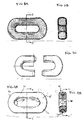
- Figure 1 shows a stud link 1 comprising a body 2 of two side limbs 3, 4 of a light weigh plastic material, such as polyurethane. At both ends the side limbs 3, 4 are mutually joined by curved steel end portions 5, 6.
- the end portions 5, 6 have the shape of a circular segment, the first end portion 5 being of a smaller curvature radius than the other end portion 6.
- the body 2 spans a band 7 of pre-tensioned unidirectional reinforcement fiber material, such as carbon fibers wound along the outer perimeter of the body 2.
- the end portions 5, 6 and the side limbs 3, 4 comprise a recess 8 extending along the outer perimeter of the body 2 to receive the band of reinforcement fiber material.
- a crossbar or stud 9 spaces the two limbs 3, 4.
- the crossbar 9 and the limbs 3, 4 are made of one single piece of a light weight plastic material, such as a polyurethane foam.
- the end portions are made of steel.
- FIG 2A shows a chain link 11 without a stud.
- the link 11 comprises a body 12 with side limbs 13, 14 and end portions 15, 16. In this particular embodiment the end portions are of equal size.
- the link 11 is shown in cross section along line B-B' in Figure 2B .
- Figure 2C the link 11 is shown in cross section along line C-C'.
- An endless band 17 of fiber material is sunk in an endless recess 18 extending along the outer perimeter of the body 12.
- the limbs 13, 14 and the end portions 15, 16 are all provided with a recess. When assembled, these recesses are in line to form the endless recess 18.
- FIG 3A shows in plan view a third embodiment of a cable link according to the invention.
- Cable link 21 comprises a body 22 (see Figure 3B ) surrounded by a sleeve 27 of a fiber material embedded in a matrix of a cured polymeric resin, such as an epoxy resin.
- the sleeve 27 has its outer ends joined to each other to form a closed loop.
- the cable link has two straight sides 23, 24, and two circularly curved end portions 25, 26.
- the body 22 is made of two C-shaped sections 28, 29, each forming a curved end portion 25, 26 at both ends extended with a half section of the straight edges 23, 24.
- Both C-shaped sections 28, 29 have one free end provided with a projection 30 and another free end provided with a correspondingly shaped recess 31.
- the sections 28, 29 are glued together to form the body 22.
- the body 22 is made of a single piece of a light weight plastic material, such as foamed polyurethane.
- Figure 4A shows a further possible chain link 41 according to the invention, shown in Figure 4B in cross section along line B-B'.
- Figure 4C shows the same chain link in longitudinal cross section along line C-C' in Figure 4B .
- a pre-tensioned fiber band 47 is sunk in a recess 48 extending over the outer perimeter of the body 42.
- one of the end portions 45 is provided with a bulge 49 on the inner perimeter of its curvature.
- the other end portion 46 is provided with a corresponding socket 50.
- the bulge 49 of each cable link 41 is shaped to cooperate with the socket 50 of an adjacent cable link 41 to form a ball joint or articulation.
Landscapes
- Engineering & Computer Science (AREA)
- General Engineering & Computer Science (AREA)
- Mechanical Engineering (AREA)
- Ropes Or Cables (AREA)
- Chain Conveyers (AREA)
Abstract
Chain link (1) comprising two side limbs (3,4) at both ends joined by curved end portions (5,6). The chain link comprises at least one endless band (7) of fiber material wound along the perimeter of the chain link. The fiber material follows the longitudinal direction of the limbs and the curvature of the end-portions. This way, all tensile loads are absorbed by the fiber material, whereas the bearing load due to interlink contact, plus the link shear and bending stresses near the contact points are absorbed by the end portions.
Description
- The invention relates to a chain link and a chain, e.g., long, high strength chains for mooring lines and tension legs used to connect offshore platforms or other buoyant marine constructions to the sea floor or anchor chains for yachts or other ships.
- Mooring lines and tension legs are generally made from steel link chain cables or polyester ropes having a diameter of between 5-18 cm. In service they carry tensile loads for long periods while submerged in sea water. The weight of steel in sea water is 92 percent of its weight in air. Therefore, due to the weight of the steel chains, the buoyancy of the offshore platforms fixed to the sea floor by such chains must be larger than otherwise required so they can buoy the lines.
- Transport and placement of steel mooring chains and tension legs is difficult due to their length and weight. Typically they are transported by ship or rail to a nearby port, and offloaded to very expensive heavy lift crane vessels or special anchor handling vessels for transportation and offshore installation. If their weight and bulk could be reduced substantially and their ability to be lengthened and shortened readily could be improved, then they could be assembled to a predetermined length and more easily transported, handled, and more rapidly installed with less expensive and more readily available support vessels.
- It has been proposed to use ropes of polyethylene fibers, such as the Dyneema® fiber of DSM. The offshore industry is already using polyester ropes for deepwater mooring applications. Such materials are approximately neutrally buoyant in sea water. The tensile strength of such materials is sufficient for long term mooring design. However, ropes have the drawback that they cannot be easily gripped, since their outer covering gets torn off, nor can they be held in place by chain stoppers. Ropes are also sensitive to the abrasive action of mud and sand particles which may penetrate and cause wear between the ropes fibers, thereby weakening of the rope. For these reasons it is often preferred to use metal chain links.
- As opposed to fiber ropes, chain links can be held in place by chain stoppers. The chain stoppers can be used to secure the chain at a specific length, thereby adjusting the tension and optimizing the related station keeping performance. Typically, a chain stopper has two latches holding the chain in place, bearing upon the shoulders of a single link. A chain is pulled through the chain stopper until the desired position, chain angle and chain tension are obtained. An example of a chain stopper is for instance disclosed in
US7240633 . - Under axial load, the individual chain links are subjected to all forms of primary stresses, i.e. bearing, bending, shear and tensile stresses. Near the contact points between links, the bearing load due to axial tension is transformed into complex stress patterns that result in the highest stress in the bar outer fibers at symmetric locations roughly +/- 45 degrees on either side of the crown. Otherwise, for a normal steel chain link, much of the steel structure is highly underutilized. This is because the existing manufacturing processes and machinery using forged round bar stock are well embedded into the traditional chain making industry, resulting in very little advancement in the chain geometry or utilization of hybrid solutions. This is particularly the case when a link is held in a chain stopper. Due to cyclic loads, the chains are also susceptible to fatigue failure. In addition, during transport or installation of the chain the individual links may be subjected to high impact loads.
- The complicated stress pattern within the individual chain links when the chain is under tensile load, hinders a straightforward use of fibers or fiber reinforced material. In fibers, the greatest strength results when the direction of the fibers is in the direction of the load. Unidirectional composite materials have a relatively low shear strength parallel to the fiber direction. Link-to-link attachments cause large stresses in the composite matrix in directions having inherently low strength.
-
US5269129 discloses a chain formed of links made of fiber-reinforced resin composite material. Each link has a terminal loop located at each axial end of a long strap. Loops, located at adjacent ends of successive links, are joined by relatively short connecting links that overlap bushings located within each of the loops. The bushings and connecting links are held in position at each lateral side of the links by pins and washers. A ring surrounds each link where the strap flares to form each terminal loop. The loops may be unitary or spaced laterally to receive within the space a unitary loop of an adjoining link aligned axially with the other loop. A pin located within the loops supports washers at each lateral side of the links to maintain the position of the links and to transfer load between the links. Such chains have the drawback that they have only moderate impact resistance. The links comprise a number of washers, pins and other separate parts resulting in an elaborate to assembling of the chain. Moreover, the strength of the chain is determined by the strength of the pins linking the chain links. The chain links are shaped rather differently from the traditional steel chain links, so their use requires modification of existing equipment and facilities, such as chain stoppers. - It is an object of the invention to provide a light-weight link chain which overcomes these problems and combines high impact resistance and high tensile strength with traditional link shape so that existing facilities, in particular chain jacks and chain stoppers, can be used with it.
- The object of the invention has been achieved by designing a chain link comprising two side limbs at both ends joint by curved end portions characterized in that the chain link comprises at least one endless band of fiber material wound along the perimeter of the chain link. The fiber material follows the longitudinal direction of the limbs and the curvature of the end-portions. This way, all tensile loads are absorbed by the fiber material, whereas the bearing load due to interlink contact, plus the link shear and bending stresses near the contact points are absorbed by the end portions. The link can be shaped in a similar configuration as traditional link shapes, so that existing facilities such as chain stoppers can be used, or may be elongated to ultimately reduce the cost per unit length of the chain.
- The endless band of fiber material can be a band of a woven or unidirectional fiber material or combinations thereof, e.g. in different layers. To secure the fiber material and to give it extra strength the fiber material can be embedded in a polymeric matrix, such as an epoxy or polyester matrix. This is especially the case when the fiber material has been wound around the chain more than once.
- A suitable material for the end portions could be similar steel as used in existing offshore mooring chains, or optionally specialty steels in the areas of high contact loads and stress, combined with other synthetic materials in the non-load bearing structure. Under tensile load, the end-portions form contact points between the various links. In use these contact points are heavily subjected to wear. By making the end portions of steel, the wear resistance of steel and the shear strength is combined with the high tensile strength of the fibers. The center-section can also be made of steel, but since the mechanical tensile stresses are carried by the fiber material, the limbs can be made out of a light weight material such as aluminum or a plastic material, such as polyurethane, polyepoxy or polyester.
- The end-portions - and optionally also the limbs - can be fitted with a recess along their outline in which the band of reinforcement fiber material is disposed. This way, the fiber material is effectively protected from impact or wear loads.
- In a specific embodiment the end-portions and the limbs can be formed by separate parts. The contact faces between these parts can for example be fitted with a pin and a corresponding pin hole or a similar joint to allow the pieces to interlock.
- It is possible to fit the inside contact areas of the end-portions with engineered surfaces, much like the way the human shoulder works. The end-portions would come in two varieties: male and female. The male variety has an extrusion, the female a recess. The male piece is able to rotate and slide in the female recess which reduces the wear normally seen between the contact areas of two chains.
- Optionally, the limbs can be linked by a stud to form an H-shaped center-section. This way, the chain becomes a studlink chain, which is less likely to get tangled than a studless chain. for example when in a chain locker or a bundle.
- The fiber material can for example be installed in a predetermined tension, e.g. with a tension designed to most effectively mobilize the available strength of the different load bearing materials considering the geometry, and the different ultimate strength and moduli of elasticity.
- Suitable fiber materials are for instance carbon fibers, polyethyelene fibers, aramide fibers and glass fibers. Suitable polyethylene fibers are for instance the Dyneema® fibers commercially available from DSM. Suitable aramide fibers are for instance Twaron®, available from Teijin, or Kevlar®, available from DuPont.
- In environments that are less extreme than offshore there another embodiment of a chain link according to the present invention can be used. With this design, is the end portions and limbs are surrounded by a sleeve of the fiber material. The end portions and limbs can for example be formed by a foam core comprising two mirrored shapes that each form half a side of a chain link. This foam can for be polyurethane, although any material would be usable. The fibers can be embedded in a polymeric matrix, e.g. an epoxy or polyester matrix. Such a design can for example be attractive for the market of pleasure yachts and the like, where chains are generally subjected to much lower mechanical loads. The chains can be designed to be buoyant and could be marketed based on a fashionable and trendy outlook.
- Such a chain link can be constructed by slipping a fiber sleeve over one of the mirrored shapes, then, the next shape would be placed next to the first one and the fiber would continue to be pulled or rolled from the first mirrored shape over the second mirrored shape. Preferably, the sleeve is somewhat longer than the perimeter of the core, so that the first end of the sleeve is slipped over its other end. This construction allows the chain to be made without any weak spots, since the fiber sleeve covers both the cores and essentially creates a one piece chain. The fiber sleeve can be made out of normal or pre-impregnated carbon fiber. However, pre-impregnated carbon fiber would have the advantage that the sleeve would not have to be treated with epoxies during application, thereby simplifying the construction process.
- The invention will now be described in more detail, by way of example only, with reference to the accompanying drawing, wherein:
- Figure 1
- shows in perspective view of a first embodiment of a cable link according to the present invention;
- Figure 2A
- shows a plan view of a second embodiment of a cable link according to the present invention;
- Figure 2B
- shows a cross section along the line B-B' in
Figure 2A ; - Figure 2C
- shows a cross section along the line C-C' in
Figure 2A ; - Figure 3A
- shows a plan view of a third embodiment of a cable link according to the present invention;
- Figure 3B
- shows a cross section along line B-B' in
Figure 3A ; - Figure 3C
- shows the body of the cable link according to
Figure 3A ; - Figure 4A
- shows a plan view of a third embodiment of a cable link according to the present invention;
- Figure 4B
- shows a cross section over line B-B' in
Figure 4A ; - Figure 4C
- shows a longitudinal cross section over line C-C' in
Figure 4B . -
Figure 1 shows a stud link 1 comprising abody 2 of twoside limbs side limbs steel end portions 5, 6. Theend portions 5, 6 have the shape of a circular segment, the first end portion 5 being of a smaller curvature radius than theother end portion 6. Thebody 2 spans a band 7 of pre-tensioned unidirectional reinforcement fiber material, such as carbon fibers wound along the outer perimeter of thebody 2. Theend portions 5, 6 and theside limbs body 2 to receive the band of reinforcement fiber material. A crossbar or stud 9 spaces the twolimbs limbs -
Figure 2A shows a chain link 11 without a stud. The link 11 comprises abody 12 withside limbs end portions 15, 16. In this particular embodiment the end portions are of equal size. The link 11 is shown in cross section along line B-B' inFigure 2B . InFigure 2C , the link 11 is shown in cross section along line C-C'. Anendless band 17 of fiber material is sunk in anendless recess 18 extending along the outer perimeter of thebody 12. Thelimbs end portions 15, 16 are all provided with a recess. When assembled, these recesses are in line to form theendless recess 18. -
Figure 3A shows in plan view a third embodiment of a cable link according to the invention. Cable link 21 comprises a body 22 (seeFigure 3B ) surrounded by a sleeve 27 of a fiber material embedded in a matrix of a cured polymeric resin, such as an epoxy resin. The sleeve 27 has its outer ends joined to each other to form a closed loop. The cable link has two straight sides 23, 24, and two circularly curved end portions 25, 26. As shown inFigure 3C , the body 22 is made of two C-shaped sections 28, 29, each forming a curved end portion 25, 26 at both ends extended with a half section of the straight edges 23, 24. Both C-shaped sections 28, 29 have one free end provided with a projection 30 and another free end provided with a correspondingly shaped recess 31. The sections 28, 29 are glued together to form the body 22. The body 22 is made of a single piece of a light weight plastic material, such as foamed polyurethane. -
Figure 4A shows a further possible chain link 41 according to the invention, shown inFigure 4B in cross section along line B-B'.Figure 4C shows the same chain link in longitudinal cross section along line C-C' inFigure 4B . As in the embodiment ofFigure 2A , a pre-tensioned fiber band 47 is sunk in arecess 48 extending over the outer perimeter of thebody 42. In this embodiment, one of theend portions 45 is provided with abulge 49 on the inner perimeter of its curvature. Theother end portion 46 is provided with a correspondingsocket 50. In an assembled chain, thebulge 49 of eachcable link 41 is shaped to cooperate with thesocket 50 of anadjacent cable link 41 to form a ball joint or articulation.
Claims (10)
- Chain link comprising two side limbs at both ends joint by curved end portions characterized in that the chain link comprises at least one endless band of fiber material wound along the perimeter of the chain link.
- Chain link according to claim 1 characterized in that at least the end portions are made of steel.
- Chain link according to claim 1 or 2 characterized in that the at least the end portions comprise a recess along their outer fiber to receive and protect the band of reinforcement fiber material.
- Chain link according to any one of the preceding claims characterized in that the side limbs are made of a plastic material.
- Chain link according to any one of the preceding claims characterized in that the fiber material is pre-tensioned.
- Chain link according to any one of the preceding claims characterized in that the fiber material is selected from the group of carbon fibers, polyethyelene fibers, aramide fibers and glass fibers.
- Chain link according to any one of the preceding claims characterized in that the link is a stud link comprising a crossbar between the two limbs.
- Chain link according to any one of the preceding claims characterized in that the band of fiber material forms a sleeve surrounding the limbs and end portions.
- Chain link according to claim 8 characterized in that the link is made of two mirrored C-shaped sections of a foamed plastic material, the sections having their free ends linked to each other.
- Chain at least partly made of chain links according to any one of the preceding claims.
Priority Applications (6)
| Application Number | Priority Date | Filing Date | Title |
|---|---|---|---|
| EP07116747A EP2039959A1 (en) | 2007-09-19 | 2007-09-19 | Chain link |
| EP08803554A EP2195551B1 (en) | 2007-09-19 | 2008-09-02 | Chain |
| US12/678,575 US8161723B2 (en) | 2007-09-19 | 2008-09-02 | Chain link |
| AT08803554T ATE532990T1 (en) | 2007-09-19 | 2008-09-02 | CHAIN |
| ES08803554T ES2377249T3 (en) | 2007-09-19 | 2008-09-02 | Chain |
| PCT/EP2008/061583 WO2009037107A1 (en) | 2007-09-19 | 2008-09-02 | Chain link |
Applications Claiming Priority (1)
| Application Number | Priority Date | Filing Date | Title |
|---|---|---|---|
| EP07116747A EP2039959A1 (en) | 2007-09-19 | 2007-09-19 | Chain link |
Publications (1)
| Publication Number | Publication Date |
|---|---|
| EP2039959A1 true EP2039959A1 (en) | 2009-03-25 |
Family
ID=39166278
Family Applications (2)
| Application Number | Title | Priority Date | Filing Date |
|---|---|---|---|
| EP07116747A Withdrawn EP2039959A1 (en) | 2007-09-19 | 2007-09-19 | Chain link |
| EP08803554A Not-in-force EP2195551B1 (en) | 2007-09-19 | 2008-09-02 | Chain |
Family Applications After (1)
| Application Number | Title | Priority Date | Filing Date |
|---|---|---|---|
| EP08803554A Not-in-force EP2195551B1 (en) | 2007-09-19 | 2008-09-02 | Chain |
Country Status (5)
| Country | Link |
|---|---|
| US (1) | US8161723B2 (en) |
| EP (2) | EP2039959A1 (en) |
| AT (1) | ATE532990T1 (en) |
| ES (1) | ES2377249T3 (en) |
| WO (1) | WO2009037107A1 (en) |
Cited By (7)
| Publication number | Priority date | Publication date | Assignee | Title |
|---|---|---|---|---|
| WO2010079437A1 (en) * | 2009-01-07 | 2010-07-15 | Bucyrus Europe Gmbh | Link chain for chain conveyors and horizontal chain links therefor |
| WO2013170259A1 (en) | 2012-05-11 | 2013-11-14 | Bardex Corporation | Mooring chain connecting link |
| WO2014029386A1 (en) * | 2012-08-20 | 2014-02-27 | Thiele Gmbh & Co. Kg | Link chain as traction means in continuous conveyors and extraction systems in mining |
| NL2015180B1 (en) * | 2015-07-16 | 2017-02-02 | Marel Stork Poultry Proc Bv | Link chain and method for producing it. |
| CN107098263A (en) * | 2016-02-23 | 2017-08-29 | 路德-李格和蒂茨链条有限公司 | For fastening, the bearing assembly with plastic-metal hybrid system of colligation and/or hoisting technology |
| EP3369964A1 (en) * | 2017-03-02 | 2018-09-05 | Rotortug Holding B.V. | Smartlink |
| US20250334169A1 (en) * | 2024-04-26 | 2025-10-30 | Abdullah Othman Fallatah | Restrainer of relative motion among chain links |
Families Citing this family (10)
| Publication number | Priority date | Publication date | Assignee | Title |
|---|---|---|---|---|
| FR2950077B1 (en) * | 2009-09-11 | 2014-07-18 | Messier Dowty Sa | METHOD FOR MANUFACTURING A FIBER-REINFORCED METAL ROD, AND ROD THUS OBTAINED |
| DE102010040495A1 (en) * | 2010-09-09 | 2012-03-15 | Siemens Aktiengesellschaft | Device for transmitting a force, in particular a carrying loop |
| US10376722B2 (en) | 2015-12-31 | 2019-08-13 | Climb Tech, Llc | Connecting and anchoring device |
| US10384086B2 (en) | 2015-12-31 | 2019-08-20 | Climb Tech, Llc | Connecting and anchoring device |
| US10363442B2 (en) | 2015-12-31 | 2019-07-30 | Climb Tech, Llc | Connecting and anchoring device |
| USD790138S1 (en) * | 2016-09-01 | 2017-06-20 | Feline Environmental Enrichment Design Company, Llc | Pet feeding device |
| US11242912B2 (en) * | 2019-02-13 | 2022-02-08 | John Dodds | Chain fastening assembly |
| CN113510947A (en) * | 2021-03-23 | 2021-10-19 | 哈尔滨玻璃钢研究院有限公司 | Method for forming composite continuous fiber chain |
| CN113021853B (en) * | 2021-03-24 | 2022-09-02 | 哈尔滨复合材料设备开发有限公司 | Winding device and winding method for producing fiber composite material endless chain |
| KR20220160927A (en) * | 2021-05-28 | 2022-12-06 | 주식회사 고려기술 | A Variable Type Chain Link for Sludge Collector and Chain Assembly connecting it with Chain Link |
Citations (11)
| Publication number | Priority date | Publication date | Assignee | Title |
|---|---|---|---|---|
| DE1135721B (en) * | 1961-04-18 | 1962-08-30 | Kettenwerke Schlieper G M B H | Round link chain made of glass fiber reinforced plastic |
| EP0098739A1 (en) * | 1982-07-01 | 1984-01-18 | Dunlop Limited | Improvements in or relating to link means |
| DE3514103A1 (en) * | 1985-04-16 | 1986-10-30 | Rud-Kettenfabrik Rieger & Dietz Gmbh U. Co, 7080 Aalen | Conveying chain |
| US4932927A (en) * | 1986-03-14 | 1990-06-12 | Envirex Inc. | High strength, non-metallic transmission chain |
| EP0564954A1 (en) * | 1992-04-09 | 1993-10-13 | Fraunhofer-Gesellschaft Zur Förderung Der Angewandten Forschung E.V. | Chain link plate and method of manufacturing the same |
| US5269129A (en) | 1992-02-14 | 1993-12-14 | Aluminum Company Of America | Chain of fiber-reinforced resin composite material |
| JPH09324376A (en) * | 1996-06-04 | 1997-12-16 | Mitsubishi Chem Corp | Tensile material using continuous fiber |
| US5956936A (en) * | 1999-01-13 | 1999-09-28 | Columbia Steel Casting Co., Inc. | Elongated chain link |
| EP1736674A1 (en) * | 2005-06-24 | 2006-12-27 | Snecma | Mechanical part and process to manufacture such a part |
| DE102005027173A1 (en) * | 2005-06-12 | 2006-12-28 | East-4D Lightweight Structures Gmbh | Force transmission unit for use in pull and push rod of aircraft, is made of fiber composite material, where pull and push straps are laterally supported within region of unit that supports entire curvature region of push strap |
| US7240633B2 (en) | 2004-04-30 | 2007-07-10 | Timberland Equipment Limited | Underwater chain stopper and fairlead apparatus for anchoring offshore structures |
Family Cites Families (12)
| Publication number | Priority date | Publication date | Assignee | Title |
|---|---|---|---|---|
| US686977A (en) * | 1899-02-16 | 1901-11-19 | John S Kidd | Driving-chain. |
| US636157A (en) * | 1899-02-21 | 1899-10-31 | Emile Gobbe | Apparatus for manufacturing chains. |
| NL222020A (en) * | 1956-11-05 | |||
| US3153898A (en) * | 1962-02-19 | 1964-10-27 | Kettenwerke Schlieper G M B H | Ringshaped members made from plastic material |
| US3733811A (en) * | 1970-06-01 | 1973-05-22 | Florjancic Peter | Process for the fabrication of a link chain |
| FR2258342B1 (en) * | 1974-01-17 | 1978-04-21 | Sietam | |
| US4559890A (en) * | 1983-04-25 | 1985-12-24 | Jet Research Center, Inc. | Mooring release apparatus and method |
| JPS61211557A (en) * | 1985-03-13 | 1986-09-19 | Tsubakimoto Chain Co | Link plate for chain |
| US4779411A (en) * | 1985-12-02 | 1988-10-25 | Link Enterprises Corporation | Flexible, non-metallic rigging chain |
| US4863418A (en) * | 1989-02-13 | 1989-09-05 | Envirex Inc. | Non-metallic chain including wound composite chain links and molded pins |
| BR0015208A (en) * | 1999-11-01 | 2002-07-09 | Offshore Energy Dev Corp | Methods of securing a ship to a subsea anchor and repairing or replacing a mooring line in a mooring system |
| US7743597B2 (en) * | 2008-08-26 | 2010-06-29 | General Pneumatics Corp. | Marine safety device attachment with automatic release capability |
-
2007
- 2007-09-19 EP EP07116747A patent/EP2039959A1/en not_active Withdrawn
-
2008
- 2008-09-02 ES ES08803554T patent/ES2377249T3/en active Active
- 2008-09-02 EP EP08803554A patent/EP2195551B1/en not_active Not-in-force
- 2008-09-02 WO PCT/EP2008/061583 patent/WO2009037107A1/en not_active Ceased
- 2008-09-02 AT AT08803554T patent/ATE532990T1/en active
- 2008-09-02 US US12/678,575 patent/US8161723B2/en not_active Expired - Fee Related
Patent Citations (11)
| Publication number | Priority date | Publication date | Assignee | Title |
|---|---|---|---|---|
| DE1135721B (en) * | 1961-04-18 | 1962-08-30 | Kettenwerke Schlieper G M B H | Round link chain made of glass fiber reinforced plastic |
| EP0098739A1 (en) * | 1982-07-01 | 1984-01-18 | Dunlop Limited | Improvements in or relating to link means |
| DE3514103A1 (en) * | 1985-04-16 | 1986-10-30 | Rud-Kettenfabrik Rieger & Dietz Gmbh U. Co, 7080 Aalen | Conveying chain |
| US4932927A (en) * | 1986-03-14 | 1990-06-12 | Envirex Inc. | High strength, non-metallic transmission chain |
| US5269129A (en) | 1992-02-14 | 1993-12-14 | Aluminum Company Of America | Chain of fiber-reinforced resin composite material |
| EP0564954A1 (en) * | 1992-04-09 | 1993-10-13 | Fraunhofer-Gesellschaft Zur Förderung Der Angewandten Forschung E.V. | Chain link plate and method of manufacturing the same |
| JPH09324376A (en) * | 1996-06-04 | 1997-12-16 | Mitsubishi Chem Corp | Tensile material using continuous fiber |
| US5956936A (en) * | 1999-01-13 | 1999-09-28 | Columbia Steel Casting Co., Inc. | Elongated chain link |
| US7240633B2 (en) | 2004-04-30 | 2007-07-10 | Timberland Equipment Limited | Underwater chain stopper and fairlead apparatus for anchoring offshore structures |
| DE102005027173A1 (en) * | 2005-06-12 | 2006-12-28 | East-4D Lightweight Structures Gmbh | Force transmission unit for use in pull and push rod of aircraft, is made of fiber composite material, where pull and push straps are laterally supported within region of unit that supports entire curvature region of push strap |
| EP1736674A1 (en) * | 2005-06-24 | 2006-12-27 | Snecma | Mechanical part and process to manufacture such a part |
Cited By (14)
| Publication number | Priority date | Publication date | Assignee | Title |
|---|---|---|---|---|
| WO2010079437A1 (en) * | 2009-01-07 | 2010-07-15 | Bucyrus Europe Gmbh | Link chain for chain conveyors and horizontal chain links therefor |
| US8631930B2 (en) | 2009-01-07 | 2014-01-21 | Caterpillar Global Mining Europe Gmbh | Link chain for chain conveyors and horizontal chain links therefor |
| WO2013170259A1 (en) | 2012-05-11 | 2013-11-14 | Bardex Corporation | Mooring chain connecting link |
| EP2847491A4 (en) * | 2012-05-11 | 2016-06-01 | Bardex Corp | LINK LINK FOR MOORING CHAINS |
| WO2014029386A1 (en) * | 2012-08-20 | 2014-02-27 | Thiele Gmbh & Co. Kg | Link chain as traction means in continuous conveyors and extraction systems in mining |
| CN104583643A (en) * | 2012-08-20 | 2015-04-29 | 蒂勒有限及两合公司 | Link chain as traction means in continuous conveyors and extraction systems in mining |
| NL2015180B1 (en) * | 2015-07-16 | 2017-02-02 | Marel Stork Poultry Proc Bv | Link chain and method for producing it. |
| CN107098263A (en) * | 2016-02-23 | 2017-08-29 | 路德-李格和蒂茨链条有限公司 | For fastening, the bearing assembly with plastic-metal hybrid system of colligation and/or hoisting technology |
| EP3210929A1 (en) * | 2016-02-23 | 2017-08-30 | RUD Ketten Rieger & Dietz GmbH u. Co. KG | Load-bearing component for stopping, lashing and/or hoisting technology with a plastic-metal composite system |
| US10072698B2 (en) | 2016-02-23 | 2018-09-11 | Rud Ketten Rieger & Dietz Gmbh U. Co. Kg | Load-bearing component for the fastening, lashing, and/or lifting technology with a plastic-metal composite system |
| CN107098263B (en) * | 2016-02-23 | 2019-06-28 | 路德-李格和蒂茨链条有限公司 | For fastening, binding and/or the bearing assembly with plastic-metal composite system of hoisting technology |
| EP3369964A1 (en) * | 2017-03-02 | 2018-09-05 | Rotortug Holding B.V. | Smartlink |
| NL2018463B1 (en) * | 2017-03-02 | 2018-09-21 | Rotortug Holding B V | Smartlink |
| US20250334169A1 (en) * | 2024-04-26 | 2025-10-30 | Abdullah Othman Fallatah | Restrainer of relative motion among chain links |
Also Published As
| Publication number | Publication date |
|---|---|
| US20100257835A1 (en) | 2010-10-14 |
| EP2195551A1 (en) | 2010-06-16 |
| ES2377249T3 (en) | 2012-03-23 |
| EP2195551B1 (en) | 2011-11-09 |
| WO2009037107A1 (en) | 2009-03-26 |
| ATE532990T1 (en) | 2011-11-15 |
| US8161723B2 (en) | 2012-04-24 |
Similar Documents
| Publication | Publication Date | Title |
|---|---|---|
| EP2195551B1 (en) | Chain | |
| US4183261A (en) | Shackle | |
| US6030145A (en) | Articulated underwater cable riser system | |
| KR102155228B1 (en) | Fairlead for guiding an anchoring element | |
| EP3980666B1 (en) | A coupling device | |
| US8517439B2 (en) | Detachable ears rope thimble | |
| CA2898167C (en) | Rope having a low-friction strand | |
| KR20120013255A (en) | Pump tower structure of LNG storage tank | |
| US5269129A (en) | Chain of fiber-reinforced resin composite material | |
| US11142288B2 (en) | Bending strain relief assembly for marine cables incorporating at least one elongated stiffness member | |
| ES2744780T3 (en) | A riser set and method of installing a riser set | |
| EP3802308B1 (en) | Toggle | |
| NO176368B (en) | Bending-limiting device | |
| EP3973100B1 (en) | Rope having an end connector segment comprising two rope-branches with unequal lengths | |
| US20120152870A1 (en) | Systems and methods for supporting tubular members | |
| KR101495645B1 (en) | Fiber rope having link for buoy fixed | |
| EP2852523B1 (en) | Securing link for anchor chain, cable or rope | |
| JP7599950B2 (en) | Mooring coupler | |
| KR102672422B1 (en) | Choke protection cover for ship and offshore structures | |
| EP4741568A1 (en) | Synthetic fiber based tendons | |
| EP4033119B1 (en) | Marine anchor chain | |
| US20070231078A1 (en) | Composite tendon | |
| EP3762323B1 (en) | Expandable heavy equipment, and elongated pull element | |
| RU73440U1 (en) | HIGH-STRENGTH LOADING FACILITY FOR SOFT CAPTURE OF LONG-LASTING GOODS (OPTIONS) | |
| KR20260028850A (en) | Flexible cable with extended life, and method for manufacturing the flexible cable |
Legal Events
| Date | Code | Title | Description |
|---|---|---|---|
| PUAI | Public reference made under article 153(3) epc to a published international application that has entered the european phase |
Free format text: ORIGINAL CODE: 0009012 |
|
| AK | Designated contracting states |
Kind code of ref document: A1 Designated state(s): AT BE BG CH CY CZ DE DK EE ES FI FR GB GR HU IE IS IT LI LT LU LV MC MT NL PL PT RO SE SI SK TR |
|
| AX | Request for extension of the european patent |
Extension state: AL BA HR MK RS |
|
| AKX | Designation fees paid | ||
| REG | Reference to a national code |
Ref country code: DE Ref legal event code: 8566 |
|
| STAA | Information on the status of an ep patent application or granted ep patent |
Free format text: STATUS: THE APPLICATION IS DEEMED TO BE WITHDRAWN |
|
| 18D | Application deemed to be withdrawn |
Effective date: 20090926 |