EP2039913A1 - Straddle type vehicle - Google Patents
Straddle type vehicle Download PDFInfo
- Publication number
- EP2039913A1 EP2039913A1 EP08253051A EP08253051A EP2039913A1 EP 2039913 A1 EP2039913 A1 EP 2039913A1 EP 08253051 A EP08253051 A EP 08253051A EP 08253051 A EP08253051 A EP 08253051A EP 2039913 A1 EP2039913 A1 EP 2039913A1
- Authority
- EP
- European Patent Office
- Prior art keywords
- throttle valve
- original position
- throttle
- opening
- protrusion
- Prior art date
- Legal status (The legal status is an assumption and is not a legal conclusion. Google has not performed a legal analysis and makes no representation as to the accuracy of the status listed.)
- Granted
Links
Images





Classifications
-
- F—MECHANICAL ENGINEERING; LIGHTING; HEATING; WEAPONS; BLASTING
- F02—COMBUSTION ENGINES; HOT-GAS OR COMBUSTION-PRODUCT ENGINE PLANTS
- F02D—CONTROLLING COMBUSTION ENGINES
- F02D11/00—Arrangements for, or adaptations to, non-automatic engine control initiation means, e.g. operator initiated
- F02D11/04—Arrangements for, or adaptations to, non-automatic engine control initiation means, e.g. operator initiated characterised by mechanical control linkages
-
- F—MECHANICAL ENGINEERING; LIGHTING; HEATING; WEAPONS; BLASTING
- F02—COMBUSTION ENGINES; HOT-GAS OR COMBUSTION-PRODUCT ENGINE PLANTS
- F02D—CONTROLLING COMBUSTION ENGINES
- F02D9/00—Controlling engines by throttling air or fuel-and-air induction conduits or exhaust conduits
- F02D9/08—Throttle valves specially adapted therefor; Arrangements of such valves in conduits
- F02D9/10—Throttle valves specially adapted therefor; Arrangements of such valves in conduits having pivotally-mounted flaps
- F02D9/1065—Mechanical control linkage between an actuator and the flap, e.g. including levers, gears, springs, clutches, limit stops of the like
-
- F—MECHANICAL ENGINEERING; LIGHTING; HEATING; WEAPONS; BLASTING
- F02—COMBUSTION ENGINES; HOT-GAS OR COMBUSTION-PRODUCT ENGINE PLANTS
- F02D—CONTROLLING COMBUSTION ENGINES
- F02D9/00—Controlling engines by throttling air or fuel-and-air induction conduits or exhaust conduits
- F02D9/08—Throttle valves specially adapted therefor; Arrangements of such valves in conduits
- F02D9/10—Throttle valves specially adapted therefor; Arrangements of such valves in conduits having pivotally-mounted flaps
- F02D9/109—Throttle valves specially adapted therefor; Arrangements of such valves in conduits having pivotally-mounted flaps having two or more flaps
- F02D9/1095—Rotating on a common axis, e.g. having a common shaft
-
- F—MECHANICAL ENGINEERING; LIGHTING; HEATING; WEAPONS; BLASTING
- F02—COMBUSTION ENGINES; HOT-GAS OR COMBUSTION-PRODUCT ENGINE PLANTS
- F02B—INTERNAL-COMBUSTION PISTON ENGINES; COMBUSTION ENGINES IN GENERAL
- F02B61/00—Adaptations of engines for driving vehicles or for driving propellers; Combinations of engines with gearing
- F02B61/02—Adaptations of engines for driving vehicles or for driving propellers; Combinations of engines with gearing for driving cycles
-
- F—MECHANICAL ENGINEERING; LIGHTING; HEATING; WEAPONS; BLASTING
- F02—COMBUSTION ENGINES; HOT-GAS OR COMBUSTION-PRODUCT ENGINE PLANTS
- F02D—CONTROLLING COMBUSTION ENGINES
- F02D9/00—Controlling engines by throttling air or fuel-and-air induction conduits or exhaust conduits
- F02D9/02—Controlling engines by throttling air or fuel-and-air induction conduits or exhaust conduits concerning induction conduits
- F02D2009/0201—Arrangements; Control features; Details thereof
- F02D2009/0254—Mechanical control linkage between accelerator lever and throttle valve
-
- F—MECHANICAL ENGINEERING; LIGHTING; HEATING; WEAPONS; BLASTING
- F02—COMBUSTION ENGINES; HOT-GAS OR COMBUSTION-PRODUCT ENGINE PLANTS
- F02D—CONTROLLING COMBUSTION ENGINES
- F02D9/00—Controlling engines by throttling air or fuel-and-air induction conduits or exhaust conduits
- F02D9/02—Controlling engines by throttling air or fuel-and-air induction conduits or exhaust conduits concerning induction conduits
- F02D2009/0201—Arrangements; Control features; Details thereof
- F02D2009/0255—Arrangements; Control features; Details thereof with means for correcting throttle position, e.g. throttle cable of variable length
-
- F—MECHANICAL ENGINEERING; LIGHTING; HEATING; WEAPONS; BLASTING
- F02—COMBUSTION ENGINES; HOT-GAS OR COMBUSTION-PRODUCT ENGINE PLANTS
- F02D—CONTROLLING COMBUSTION ENGINES
- F02D9/00—Controlling engines by throttling air or fuel-and-air induction conduits or exhaust conduits
- F02D9/02—Controlling engines by throttling air or fuel-and-air induction conduits or exhaust conduits concerning induction conduits
- F02D2009/0201—Arrangements; Control features; Details thereof
- F02D2009/0277—Fail-safe mechanisms, e.g. with limp-home feature, to close throttle if actuator fails, or if control cable sticks or breaks
Definitions
- the present invention relates to a straddle type vehicle.
- the electronic throttle valve system enables the control of the throttle valve regardless of an operation of an acceleration grip and the like by a rider. This allows for an advanced control compared to the conventional systems.
- the present invention seeks to achieve a straddle type vehicle having an electronic throttle valve and capable of executing with advanced control compared to a conventional vehicles.
- a straddle type vehicle includes: a throttle valve for adjusting the amount of air intake of an engine; an acceleration controller operated by a rider for opening and closing the throttle valve; an electric motor for actuating the throttle valve; a first member displaced together with the throttle valve in a state that a position of the first member when the throttle valve is fully closed is set as a first original position; a second member displaced in accordance with the acceleration controller in a state that a position of the second member when the acceleration controller is fully closed is set as a second original position; an elastic body that is interposed between the first member and the second member when at least the first member and the second member are in the first original position and the second original position, respectively, and that generates restoring force to return the first member to the first original position when the second member is in the second original position, and maintains the second member in the second original position by being elastically deformed until the first member reaches a predetermined position when the first member is displaced from the first original position to a direction in which the throttle valve opens in
- the straddle type vehicle may further include: a multistage transmission; an input device for receiving a shift change command from the rider; and a shift actuator for driving the transmission to perform a shift change when the shift change command is input in the input device, and the predetermined control may be a shift change by the shift actuator performed when the acceleration controller is fully closed.
- blipping is able to be performed using the first member, the second member, and the elastic body each of which is used for other than blipping. This allows for blipping without providing an additional special blipper.
- the straddle type vehicle may further include: a vehicle speed sensor for detecting a vehicle speed, and the predetermined control may be a control of adjusting the opening of the throttle valve so that the vehicle speed becomes a predetermined value in a range in which the first member is positioned between the first original position and the predetermined position.
- the vehicle speed can be maintained at a predetermined value regardless of the opening of the acceleration controller. This allows for a so-called cruise control.
- the straddle type vehicle may further include: a multistage transmission; a drive wheel; a driven wheel; a first sensor for detecting a rotation speed of the drive wheel; and a second sensor for detecting a rotation speed of the driven wheel, and the predetermined control may be a control of adjusting the opening of the throttle valve so that the difference between the rotation speed of the drive wheel and the rotation speed of the driven wheel is not greater than a predetermined value at a shift down of the transmission.
- the opening of the throttle valve is adjusted so that the speed difference is not greater than the predetermined value.
- the throttle valve is opened so that the speed difference is not increased. This prevents an excessive engine brake.
- An embodiment of a straddle type vehicle according to the invention can provide an electronic throttle valve capable of advanced control compared to conventional vehicles.
- an Automated Manual Transmission which automatically performs the shift change by using an actuator has been known.
- an electronic throttle valve system for automatically controlling a throttle valve has also been known.
- a method for the quick shift change by performing so-called blipping without disengaging a clutch has been known.
- a method for the smooth shift change by performing blipping after disengagement of a clutch at shift changes in order to mitigate a shock during subsequent clutch engagement has also been known. It should be noted that in this specification, "blipping" means increasing the rotation speed of an engine temporarily by sharply opening the throttle valve temporarily.
- JP-A-2002-67741 there is a description of providing a blipper for idling of an engine in a two-wheeled motor vehicle having an AMT and an electronic throttle valve.
- the straddle type vehicle according to the present embodiment allows for blipping without providing a special blipper in a straddle type vehicle having an AMT and an electronic throttle valve.
- the two-wheeled motor vehicle 1 of a motorcycle type shown in FIG. 1 will be explained as an example of a straddle type vehicle embodying the present invention.
- the two-wheeled motor vehicle 1 is not limited to this.
- the two-wheeled motor vehicle 1 may be two-wheeled motor vehicles of a so-called moped type, a scooter type, an off-road type and the like other than the so-called motorcycle type.
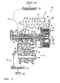
- FIG. 1 is a left side view of a two-wheeled motor vehicle 1 according to the embodiment 1.
- the outline configuration of the two-wheeled motor vehicle 1 will be explained.
- the directions such as the front, the rear, the left, and the right refer to directions viewed by a rider sitting on a seat 9.
- the two-wheeled motor vehicle 1 includes a body frame 2.
- the body frame 2 has a head pipe 2a.
- a handle bar 3 is mounted on an upper end of the head pipe 2a, and a front wheel 5 is mounted to a lower end of the head pipe 2a through front forks 4 in a freely rotatable manner.
- a swing arm 6 capable of oscillating is attached to a rear end of the body frame 2.
- a rear wheel 7 is mounted in a rotatable manner to the rear end of the swing arm 6.
- the reference number 8 denotes a fuel tank.
- the seat 9 is provided at the rear side of the fuel tank 8.
- a power unit 10 including an engine 12 as a driving source is suspended from the body frame 2.
- the power unit 10 is connected to the rear wheel 7 through a power transmission means 11 such as a chain, a belt and a drive shaft. This allows the power transmission means 11 to transmit driving force to the rear wheel 7, the driving force being generated in the power unit 10 by the engine 12.
- the power unit 10 includes the engine 12, a transmission 13 and a clutch 14.
- the invention is not limited to a particular type of engine.
- the engine 12 is of a water-cooled 4-cycle parallel 4-cylinder type.
- the engine 12 may be of an air-cooled type, and the number of cylinders is not limited to four.
- the engine may be a 2-cycle engine.
- the engine 12 is disposed in a manner that a cylinder shaft (not shown) extends slightly obliquely upward to the front of a body.
- the engine 12 has a crankshaft 21 housed in a crankcase (not shown).
- the crankshaft 21 is disposed so as to extend in the width direction of the vehicle.
- An engine rotation speed sensor S30 is attached to an end of the crankshaft 21.
- the crankshaft 21 is connected to the transmission 13 through the clutch 14.
- the transmission 13 is a multistage transmission and includes a main shaft 22, a drive shaft 23 and a gear selection mechanism 24.
- the main shaft 22 is connected to the crankshaft 21 through the clutch 14.
- the main shaft 22 and the drive shaft 23 are each disposed substantially parallel to the crankshaft 21.
- a main shaft rotation speed sensor S31 is provided on the main shaft 22.
- a plurality of gears 25 are mounted on the main shaft 22.
- a plurality of gears 26 are mounted on the drive shaft 23 to correspond to the gears 25. Engagement between the plural gears 25 and the plural gears 26 is achieved only through a pair of selected gears 25 and 26.
- the plural gears 25 and 26 at least either the gears 25 except the selected gear 25 or the gears 26 except the selected gear 26 are rotatable with respect to the main shaft 22 or the drive shaft 23. In other words, at least either the unselected gears 25 or the unselected gears 26 idle with respect to the main shaft 22 or the drive shaft 23.
- rotation transmission between the main shaft 22 and the drive shaft 23 is achieved only through the selected gears 25 and 26 which engage with each other.
- a shift cam 27 of the gear selection mechanism 24 performs the selection of the gears 25 and 26.
- a plurality of cam grooves 27a are formed on the outer peripheral surface of the shift cam 27.
- a shift fork 28 is mounted to each cam groove 27a.
- Each shift fork 28 engages with a predetermined gear 25 of the main shaft 22 and a predetermined gear 26 of the drive shaft 23, respectively.
- the shift cam 27 is rotated, by means of the cam groove 27a each of the plural shift forks 28 is guided to move in the axial direction of the main shaft 22. This allows for selection of the gears to engage with each other among the gears 25 and 26.
- the gear selection mechanism 24 is connected to a shift actuator 16 through a shift power transmission means 15. This allows the shift actuator 16 to drive the gear selection mechanism 24.
- the clutch 14 is a multi-plate friction clutch and includes a cylindrical clutch housing 31, a cylindrical clutch boss 32, a plurality of friction discs 33 and clutch plates 34 serving as friction plates and a pressure plate 35. Moreover, the clutch 14 includes a gear 29 to mesh with a gear 21a formed on the crankshaft 21.
- the clutch housing 31 is formed in the shape of a cylinder and mounted to the main shaft 22 in a relatively rotatable manner. On an inner peripheral surface of the clutch housing 31, a plurality of grooves extending in the axial direction of the main shaft 22 are formed.
- Each friction disc 33 is formed in the shape of a thin-plate ring.
- a plurality of teeth are formed on the outer periphery of each friction disc 33. Engagement between the plural teeth formed on the outer periphery of the friction disc 33 and the plural grooves formed on the inner peripheral surface of the clutch housing 31 enables each friction disc 33 to be mounted to the clutch housing 31 in a relatively unrotatable manner. Additionally, each friction disc 33 is mounted in a slidable manner in the axial direction of the main shaft 22 with respect to the clutch housing 31.
- the clutch boss 32 is formed in the shape of a cylinder and disposed at inner side in the radial direction of the main shaft 22 compared to the clutch housing 31. Moreover, the clutch boss 32 is mounted to the main shaft 22 in a relatively unrotatable manner. On an outer peripheral surface of the clutch boss 32, a plurality of grooves extending in the axial direction of the main shaft 22 are formed.
- Each clutch plate 34 is formed in the shape of a thin-plate ring.
- a plurality of teeth are formed on the inner periphery of each clutch plate 34. Engagement between the plural teeth formed on the inner periphery of the clutch plate 34 and the plural grooves formed on the outer peripheral surface of the clutch boss 32 enables each clutch plate 34 to be mounted to the clutch boss 32 in a relatively unrotatable manner. Additionally, each clutch plate 34 is mounted in a slidable manner in the axial direction of the main shaft 22 with respect to the clutch boss 32.
- Each friction disc 33 is mounted to the clutch housing 31 such that its plate surface is substantially orthogonal to the axial direction of the main shaft 22.
- Each clutch plate 34 is mounted to the clutch boss 32 such that its plate surface is substantially orthogonal to the axial direction of the main shaft 22.
- Each friction disc 33 and each clutch plate 34 are alternately disposed in the axial direction of the main shaft 22.
- the pressure plate 35 is formed substantially in the shape of a disc and mounted in a slidable manner in the axial direction of the main shaft 22 with respect to the clutch boss 32.
- the pressure plate 35 is mounted in a freely rotatable manner to one end of a push rod 37 (the right side in FIG. 2 ), which is disposed in the cylindrical main shaft 22, through a bearing 36 such as a deep-grooved ball bearing.
- a spherical ball 38 adjacent to the other end of the push rod 37 (the left end) is provided in the cylindrical main shaft 22 .
- a push rod 39 adjacent to the ball 38 is provided on the left side of the ball 38 .
- One end of the push rod 39 protrudes from the other end of the cylindrical main shaft 22 (the left end).
- the protruding one end of the push rod 39 is connected to a clutch actuator 18 through a clutch power transmission means 17.
- the shift actuator 16 and the clutch actuator 18 are each connected to a control device (ECU: Electronic Control Unit) 100 to be driven by the control device 100.
- ECU Electronic Control Unit
- FIG. 2 although two control devices 100 are shown for drawing convenience, these components are identical.
- the control device 100 starts shift control. Initially, the control device 100 drives the clutch actuator 18 and disengages the clutch 14 to have a disengaged state. Next, the control device 100 drives the shift actuator 16 to cause the gear selection mechanism 24 to select the desired gears 25 and 26. Thereafter, the control device 100 drives the clutch actuator 18 again to engage the clutch 14.
- an input device a shift up switch 61a or a shift down switch 61b which will be described later
- the two-wheeled motor vehicle 1 includes an electronic throttle valve system 70 for adjusting the amount of air intake of the engine 12.
- an electronic throttle valve system 70 for adjusting the amount of air intake of the engine 12.
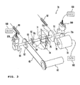
- FIG. 3 is a perspective view, schematically showing a configuration of the electronic throttle valve system 70 according to this embodiment.
- FIGs. 4 and 5 are a side perspective view and a plan perspective view showing a state that the electronic throttle valve system 70 according to this embodiment is mounted in the two-wheeled motor vehicle 1.
- the electronic throttle valve system 70 of this embodiment includes a throttle valve 71 for adjusting the amount of air intake of the engine 12 and an electric motor 72 for actuating the throttle valve 71.
- the electric motor 72 is in electrical connection with the control device 100 and driven by the control device 100.
- the throttle valve 71 is fixed to a valve shaft 73.
- the throttle valve 71 of this embodiment which is a butterfly throttle valve, is disposed within a throttle body 74.
- the throttle body 74 is provided with a fuel injection device (an injector) 75 for injecting fuel.
- FIG. 3 solely illustrates one throttle valve 71 for easier understanding although a plurality of throttle valves 71 (equal to the number of cylinders, that is, four throttle valves in this embodiment) are provided in each of the plurality of throttle bodies 74 (four throttle bodies in this embodiment).
- the electric motor 72 is connected to the valve shaft 73.
- the electric motor 72 is connected to a midsection 73c between a right end 73a and a left end 73b of the valve shaft 73.
- FIG. 3 illustrates the electric motor 72 connected to the valve shaft 73 through a drive gear 76.
- a return spring 82 is provided in the drive gear 76. With this configuration, the electric motor 72 actuates the throttle valve 71 to be opened and closed.
- the valve shaft 73 is provided with a throttle opening sensor S40 for detecting the opening of the throttle valve 71.
- the throttle opening sensor S40 is located on the right end 73a of the valve shaft 73.
- the throttle opening sensor S40 is in electrical connection with the control device 100.
- the valve shaft 73 is provided with a mechanical throttle valve actuating mechanism 50 (hereinafter, it is referred to as "mechanical actuating mechanism 50" for convenience).
- the mechanical actuating mechanism 50 is located on the left end 73b of the valve shaft 73.
- the mechanical actuating mechanism 50 is designed to actuate the throttle valve 71 in conjunction with the operation of a throttle grip 60 which is an acceleration controller in the event that the electric motor 72 stops actuating the throttle valve 71.
- the throttle grip 60 which is the acceleration controller is provided on a right end of the handle bar 3 of the two-wheeled motor vehicle 1.
- the throttle grip 60 and the mechanical actuating mechanism 50 are connected by a throttle cable 62 such that the throttle grip 60 and the mechanical actuating mechanism 50 can operate in conjunction with each other.
- a grip 61 is provided on a left end of the handle bar 3.
- a switch box 63 is provided on a right end of the grip 61.
- the switch box 63 has the shift up switch 61a and the shift down switch 61b, which are input devices for receiving a shift change command from the rider. It should be noted that the input devices are not limited to the shift up switch 61a and the shift down switch 61b, and other embodiments in various forms are acceptable.
- the mechanical actuating mechanism 50 includes a pulley 52, a lever pulley 54 and a shaft portion 53. Moreover, the mechanical actuating mechanism 50 has an accelerator-opening sensor S70 for detecting the displacement of the throttle grip 60 which is the acceleration controller.
- the accelerator-opening sensor S70 is in electrical connection with the control device 100, and the control device 100 controls the electric motor 72 based on the opening of the accelerator (i.e. the displacement of the throttle grip 60) detected by the accelerator-opening sensor S70.
- FIG. 3 illustrates three control devices 100 for convenience of description, but indeed there exists only one control device. It should be noted that plural control devices 100 may be connected to one another.
- the pulley 52 and the lever pulley 54 are each formed substantially in the shape of a disc in which a part is notched. Moreover, a center portion of the pulley 52 and a center portion of the lever pulley 54 are connected by the shaft portion 53 in a relatively unrotatable manner. This means that the lever pulley 54 rotates in conjunction with rotation of the pulley 52.
- the aforementioned throttle cable 62 engages with the pulley 52.
- the pulley 52 is provided with a return spring 80.
- the pulley 52 and the lever pulley 54 are housed in a cover 59 of the mechanical actuating mechanism 50 (see FIG. 5 ).
- the pulley 52 and the lever pulley 54 are coaxially coupled (through the shaft portion 53).
- the pulley 52 and the lever pulley 54 may be coupled, such that the lever pulley 54 can rotate in conjunction with rotation of the pulley 52.
- the above pulleys may be coupled through a link member 56 capable of varying a lever ratio.
- link member 56 capable of varying a lever ratio.
- the lever pulley 54 includes a notched portion 55 which is substantially in the shape of a sector.
- the notched portion 55 can come into contact with a protrusion 77 extending from the valve shaft 73 of the throttle valve 71.
- the protrusion 77 and the lever pulley 54 correspond to a first member and a second member of the present invention, respectively.
- a position of the protrusion 77 (the first member) when the throttle valve 71 is fully closed (the throttle opening is 0°) is determined as a first original position P1
- a position of the lever pulley 54 (the second member) when the throttle grip 60 (the acceleration controller) is fully closed is determined as a second original position P2.
- the lever pulley 54 is provided with a spring 51 as an elastic body.
- the spring 51 is designed to be interposed between the protrusion 77 and the lever pulley 54 at least when the lever pulley 54 is located in the second original position P2 (a position when the throttle grip 60 is fully closed).
- the spring 51 is designed so as to generate restoring force to return the protrusion 77 to the first original position P1 when the lever pulley 54 is located in the second original position P2.
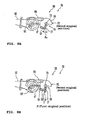
- FIG. 6A illustrates that the throttle grip 60 and the throttle valve 71 are fully closed (the acceleration opening is 0° and the throttle opening is 0°), in which peripheral members such as the injector 75 and the cover 59 are also shown for a reference purpose.
- FIG. 6B shows the condition immediately after the throttle grip 60 is sharply opened (the acceleration opening is ⁇ 1 (fully opened) and the throttle opening is ⁇ 2 , wherein ⁇ 1 > ⁇ 2 ), following the condition of FIG. 6A .
- FIG. 7B shows the intermediate step of closing the throttle grip 60 sharply (the acceleration opening is ⁇ 4 , and the throttle opening is ⁇ 5 , wherein ⁇ 1 > ⁇ 4 and ⁇ 3 > ⁇ 5 ), following the condition of FIG. 7A .
- FIG. 8A shows the throttle grip 60 further closed (the acceleration opening is 0°, and the throttle opening is ⁇ 6 , wherein ⁇ 5 > ⁇ 6 ), following the condition of FIG. 7B .
- FIG. 8B shows that the throttle grip 60 and the throttle valve 71 are fully closed (the acceleration opening is 0°, and the throttle opening is 0°).
- the pulley 52 has the opening of 0° while the protrusion (claw) 77 has the opening of 0°, the opening of the protrusion 77 being affected by the opening of the throttle valve 71 (opening of the butterfly valve).
- the link member 56 can move to the point 56' indicated by the dotted line in FIG. 6A if the throttle valve is fully opened.
- a distal end of the spring 51 which protrudes from the edge face of the notched portion 55 of the lever pulley 54, generally comes into contact with the protrusion 77.
- the spring 51 is located so as to generally come into contact with the protrusion 77 when the throttle valve 71 is closed.
- the throttle grip 60 when the throttle grip 60 is sharply turned as described above, the torque of the throttle grip 60 is transmitted to the pulley 52 by the throttle cable 62 and the pulley 52 rotates sharply.
- the pulley 52 has the opening of ⁇ 1 (e. g. 80°), which is an angle for fully opening the throttle valve 71, the lever pulley 54 also rotates through the link member 56 by the angle of ⁇ 1 . This allows the edge face and the spring 51 on the notched portion 55 of the lever pulley 54 to rotate by a predetermined angle in accordance with the angle of ⁇ 1 .
- the accelerator-opening sensor S70 detects the opening of the throttle grip 60 (opening of the accelerator) and sends data thereof to the control device 100. Based on the detected data, the control device 100 controls the electric motor 72 to rotate the valve shaft 73. In this operation, for example, when the valve shaft 73 is rotated by the angle of ⁇ 2 (e.g. 60°), the throttle valve 71 and the protrusion 77, which are fixed to the valve shaft 73, also rotate by the angle of ⁇ 2 (see FIG. 6B ).
- the angle of ⁇ 2 e.g. 60°
- the response speed of the lever pulley 54 which is in mechanical connection with the throttle grip 60, is faster than that of the throttle valve 71 and the protrusion 77, which are in electrical connection with the throttle grip 60.
- the target opening of the throttle valve 71 becomes greater than the resultant opening, so that the distal end of the spring 51 moves away from the protrusion 77.
- the mechanical, actuating mechanism 50 operates as described below in such abnormal situations that the electric motor 72 stops actuating the throttle valve 71 due to the interruption of the current from the electric motor 72 and the like and that the throttle valve 71 remains open and cannot be closed.
- the throttle valve 71 cannot be closed due to malfunction of the electric motor 72, it can be closed by the mechanical, actuating mechanism 50. More specifically, in the event that the electric motor 72 stops actuating the throttle valve 71, when the throttle grip 60 is normally turned in such a direction that the throttle valve 71 is closed, the lever pulley 54 which is in mechanical connection with the throttle grip 60 rotates. On the other hand, the protrusion 77 does not move due to stoppage of the electric motor 72. However, by means of rotation of the lever pulley 54, the protrusion 77 contacts to the lever pulley 54. Then, as the spring 51 is compressed, the protrusion 77 and the lever pulley 54 are in the condition shown in FIG. 7B . After that, the protrusion 77 is pushed by the edge face and the spring 51 on the notched portion 55 of the lever pulley 54 for being rotated. This results in the throttle valve 71 being closed.
- a shift change command is sent to the control device 100.
- the control device 100 determines whether or not the opening of the throttle grip 60 (opening of the accelerator) detected by the accelerator-opening sensor S70 is 0°. If the opening of the accelerator is 0°, the control device 100 performs the shift change with blipping.
- the control device 100 performs so-called blipping in which the electric motor 72 is driven to open the throttle valve 71 sharply so that the rotational speed of the engine is increased temporarily. After the blipping, the control device 100 actuates the shift actuator 16 for the shift change without disengaging the clutch 14.
- the electronic throttle valve system 70 operates as described below.
- the electronic throttle valve system 70 is in the condition shown in FIG. 8B .
- the control device 100 drives the electric motor 72 to sharply open the throttle valve 71 in a range that the opening of the throttle valve 71 (the protrusion 77) is less than or equal to ⁇ 6 .
- the control device 100 drives the electric motor 72 so that the opening of the throttle valve 71 is ⁇ 7 (wherein ⁇ 7 ⁇ ⁇ 6 ).
- the throttle valve 71 and the protrusion 77 (the first member) are displaced in an opening direction from the fully closed state.
- the spring 51 is designed so as to be elastically deformed until the protrusion 77 returns to a predetermined position (a position in which the throttle opening is ⁇ 6 (see FIG. 8A ) in a case where the protrusion 77 is displaced from the first original position P1 in such a direction that the throttle valve 71 opens when the lever pulley 54 is in the second original position P2.
- a predetermined position a position in which the throttle opening is ⁇ 6 (see FIG. 8A ) in a case where the protrusion 77 is displaced from the first original position P1 in such a direction that the throttle valve 71 opens when the lever pulley 54 is in the second original position P2.
- blipping is performed instead of disengagement of the clutch 14 in this embodiment, blipping may be performed after disengagement of the clutch 14. In such a case, a shock, which occurs in re-engagement of the clutch after a shift change, can be mitigated. This achieves a smooth shift change.
- blipping is able to be performed using the protrusion 77 (the first member) which is designed to improve responsiveness in fully closing control of the throttle valve 71, the lever pulley 54 (the second member) and the spring 51 (the elastic body).
- blipping is performed without additionally providing a special blipper for blipping.
- the spring 51 is designed to maintain the lever pulley 54 in the second original position P2 by being elastically deformed until the protrusion 77 returns to a predetermined position (a position in which the throttle opening is ⁇ 6 (see FIG. 8A )) in a case where the protrusion 77 is displaced from the first original position P1 in such a direction that the throttle valve 71 opens when the lever pulley 54 is in the second original position P2.
- a predetermined position a position in which the throttle opening is ⁇ 6 (see FIG. 8A )
- the throttle opening ⁇ 6 is set to be greater than or equal to 30 degrees.
- the spring 51 is set to generate elastic force to return the protrusion 77 to the first original position P1 when the lever pulley 54 is in the second original position P2. Consequently, in the aforementioned abnormal situation and the like where the throttle grip 60 is closed in a condition that the throttle valve 71 has the opening of greater than or equal to ⁇ 6 , after the lever pulley 54 is displaced to the second original position P2 while pushing the protrusion 77, the protrusion 77 is pushed by the elastic force of the spring 51 to return to the first original position P1. This makes the movement of the throttle valve 71 just before a fully closed condition slow down.
- a shock which occurs when the throttle grip 60 is returned is mitigated.
- both the function of mitigating a shock when the throttle grip 60 is returned and the function of blipping can be achieved simultaneously.
- the elastic body according to the present invention is constituted by the spring 51.
- the elastic body according to the present invention is not limited to the spring 51.
- the elastic body according to the present invention may be a rubber, for example.
- the spring 51 helps actuate the throttle valve 71 smoothly can be obtained not only in the embodiment in which the pulley 52 and the lever pulley 54 are coupled through the aforementioned link member 56, but also in another embodiment in which the pulley 52 and the lever pulley 54 are coupled coaxially through the shaft portion 53 shown in FIG. 3 .
- the mitigation of a shock by the spring 51 when the throttle grip 60 is returned is obtained not only in the embodiment in which the pulley 52 and the lever pulley 54 are coupled through the link member 56, but also in another embodiment in which the pulley 52 and the lever pulley 54 are coupled coaxially through the shaft portion 53 shown in FIG. 3 .
- the protrusion 77 rotating together with the throttle valve 71 constitutes the first member
- the lever pulley 54 rotating in accordance with the throttle grip 60 constitutes the second member of the present invention.
- components constituting the first member and the second member are not limited to these.
- the first member may be constituted by a first sliding member which slides in accordance with rotation of the throttle valve 71
- the second member may be constituted by a second sliding member which slides in accordance with rotation of the throttle grip 60.
- the two-wheeled motor vehicle 1 allows for a so-called cruise control in which running at a constant speed is achieved without an operation of the throttle grip 60 by the rider.
- the two-wheeled motor vehicle 1 includes the throttle valve system 70 similar to that of the first embodiment.
- the same components as those of the first embodiment are assigned the same reference numerals and symbols, and their explanations are omitted.
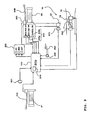
- FIG. 9 illustrates a configuration of a control system according to the present embodiment.
- this control system includes the ECU 100 as a control device and a vehicle speed sensor 201.
- the vehicle speed sensor 201 is a sensor that detects the running speed of the two-wheeled motor vehicle 1.
- the specific configuration of the vehicle speed sensor 201 is not limited at all. For example, it may be a sensor that detects the rotation speed of the front wheel 5 or the rear wheel 7, or it may calculate the vehicle speed based on the engine rotation speed.
- the ECU 100 has a storage device 210 such as a memory.
- a switch 206a input when a cruise control is started and a switch 206b input when the cruise control is stopped are disposed adjacent to the throttle grip 60.
- the switches 206a and 206b are connected to the ECU 100.
- the ECU 100 starts the cruise control when the switch 206a is input.
- the ECU stops the cruise control when the switch 206b is input during the cruise control.
- the ECU 100 is connected to a brake sensor 203 that detects the input of a front brake 60B and a brake sensor 205 that detects the input of a rear brake 204.
- the brake sensor 203 or 205 transmits a signal to the ECU 100, so that the ECU 100 can detect that the brake is applied.
- the ECU 100 stops the cruise control when it receives a signal from the brake sensor 203 or 205 during the cruise control.
- the two-wheeled motor vehicle 1 has a display 206 that displays an execution state or a non-execution state of the cruise control.
- the cruise control starts when the rider inputs the switch 206a.
- the cruise control is executed by the ECU 100 as follows. That is, the ECU 100 stores in the storage device 210 the vehicle speed at the time when the switch 206a is input as a target vehicle speed. Then, the opening of the throttle valve 71 is adjusted so that the vehicle speed detected by the vehicle speed sensor 201 becomes the target vehicle speed. Specifically, the electric motor 72 is controlled so that the vehicle speed becomes the target vehicle speed. This enables the cruise control and the two-wheeled motor vehicle 1 executes a constant speed running at the target vehicle speed.
- the spring 51 is provided between the protrusion 77 extending from the valve shaft 73 of the throttle valve 71 and the lever pulley 54. Accordingly, the throttle valve 71 is controlled in a range in which the spring 51 can be displaced without opening the throttle grip 60.
- the control of the throttle valve 71 is allowed even when the throttle grip 60 is fully closed, so that the cruise control can be executed.
- a lock mechanism that maintains an open state of the throttle grip 60 may be provided so that the throttle grip 60 is maintained at a predetermined opening (a fixed opening) during the cruise control.
- a predetermined opening a fixed opening
- the rotatable angle of the protrusion 77 becomes larger.
- the protrusion 77 can rotate by an angle larger than ⁇ 6 .
- the control range of the throttle valve 71 becomes larger.
- the cruise control can be executed.
- the two-wheeled motor vehicle 1 enables to prevent an excessive engine brake without an operation of the throttle grip 60 by the rider at a shift down during running.
- the two-wheeled motor vehicle 1 includes the throttle valve system 70 similar to that of the first embodiment.
- the same components as those of the first and second embodiments are assigned the same reference numerals and symbols, and their explanations are omitted.
- FIG. 10 illustrates a configuration of a control system according to the present embodiment.
- this control system includes the ECU 100 as a control device, a front wheel vehicle speed sensor 213 that detects the rotation speed of the front wheel 5 which is a driven wheel, and a rear wheel vehicle speed sensor 214 that detects the rotation speed of the rear wheel 7 which is a drive wheel.
- this control system includes an engine rotation speed sensor 210 that detects an engine rotation speed, a shift pressure sensor 211 that detects a shift pressure, and a gear position sensor 212 that detects a gear position of the transmission.
- this control system includes the brake sensor 203 that detects the input of the front brake 60B and the brake sensor 205 that detects the input of the rear brake 204 similarly to the second embodiment.
- a switch 215 is disposed adjacent to the throttle grip 60.
- the switch 215 is a switch that executes an ON/OFF operation of the engine brake control described later. When the switch 215 is turned ON, the engine brake control is executed, and when the switch is turned OFF, the engine brake control is not executed.
- the two-wheeled motor vehicle 1 according to the present embodiment includes a display 216 that displays an OFF/OFF state of the engine brake control.
- the engine brake control is executed by the ECU 100 as follows. That is, the ECU 100 compares the rotation speed of the front wheel 5 and the rotation speed of the rear wheel 7 in a case where the shift pressure increases as shown in FIG. 11A or the gear position becomes one step lower as shown FIG. 11B , and when the speed difference between the front wheel 5 and the rear wheel 7 exceeds a predetermined value, the ECU 100 makes the opening of the throttle valve 71 larger temporarily by controlling the electric motor 72 (refer to the reference symbol BC in FIG. 11C ). This enables the engine rotation speed to increase temporarily at a shift down, so that the speed difference is maintained not greater than the predetermined value. This results in prevention of the excessive engine brake.
- the spring 51 is provided between the protrusion 77 extending from the valve shaft 73 of the throttle valve 71 and the lever pulley 54 (refer to FIG. 8A ). Accordingly, the throttle valve 71 is controlled in a range in which the spring 51 can be displaced without opening the throttle grip 60.
- the excessive engine brake is prevented without an operation of the throttle grip 60 by the rider. That is, an automatic prevention of the excessive engine brake can be executed at a shift down.
- the wheel diameter is different between the front wheel 5 and the rear wheel 7.
- the rotation speed may be defined as a rotation angle per unit time (rad/s), and moreover, compensation may be made in accordance with the wheel diameter.
- the above predetermined value which is a standard of the speed difference in executing the engine brake control, may be set to a value previously in consideration of the difference of the wheel diameter between the front wheel 5 and the rear wheel 7.
- Straddle type vehicles according to the present invention are not limited to two-wheeled motor vehicles. Other than two-wheeled motor vehicles, four-wheeled buggies (ATV: All Terrain Vehicle) and snowmobiles are applicable.
- ATV All Terrain Vehicle
- This invention is applicable to straddle type vehicles.
Landscapes
- Engineering & Computer Science (AREA)
- Chemical & Material Sciences (AREA)
- Combustion & Propulsion (AREA)
- Mechanical Engineering (AREA)
- General Engineering & Computer Science (AREA)
- Control Of Throttle Valves Provided In The Intake System Or In The Exhaust System (AREA)
- Control Of Vehicle Engines Or Engines For Specific Uses (AREA)
- Electrical Control Of Air Or Fuel Supplied To Internal-Combustion Engine (AREA)
- Automatic Cycles, And Cycles In General (AREA)
Abstract

Description
- The present invention relates to a straddle type vehicle.
- Conventionally, in a straddle type vehicle such as a two-wheeled motor vehicle, an electronic throttle valve system that controls a throttle valve automatically has been known (See for example,
JP-A1-WO2005-047671 - The electronic throttle valve system enables the control of the throttle valve regardless of an operation of an acceleration grip and the like by a rider. This allows for an advanced control compared to the conventional systems.
- The present invention seeks to achieve a straddle type vehicle having an electronic throttle valve and capable of executing with advanced control compared to a conventional vehicles.
- A straddle type vehicle according to the present invention includes: a throttle valve for adjusting the amount of air intake of an engine; an acceleration controller operated by a rider for opening and closing the throttle valve; an electric motor for actuating the throttle valve; a first member displaced together with the throttle valve in a state that a position of the first member when the throttle valve is fully closed is set as a first original position; a second member displaced in accordance with the acceleration controller in a state that a position of the second member when the acceleration controller is fully closed is set as a second original position; an elastic body that is interposed between the first member and the second member when at least the first member and the second member are in the first original position and the second original position, respectively, and that generates restoring force to return the first member to the first original position when the second member is in the second original position, and maintains the second member in the second original position by being elastically deformed until the first member reaches a predetermined position when the first member is displaced from the first original position to a direction in which the throttle valve opens in a state that the second member is in the second original position; and a control device for opening the throttle valve by driving the electric motor and displacing the first member until the first member reaches at most the predetermined position at a predetermined control.
- The straddle type vehicle may further include: a multistage transmission; an input device for receiving a shift change command from the rider; and a shift actuator for driving the transmission to perform a shift change when the shift change command is input in the input device, and the predetermined control may be a shift change by the shift actuator performed when the acceleration controller is fully closed.
- In the straddle type vehicle as described above, even when the second member is in the second original position, since the acceleration controller is fully closed the throttle valve is able to be opened without displacing the second member. This allows for so-called blipping in which the rotation speed of an engine is temporarily increased by opening the throttle valve sharply and temporarily even without a special blip mechanism, or blipper. Thus, a quick shift change is achieved by performing blipping at shift changes.
- In addition, according to the straddle type vehicle as described above, blipping is able to be performed using the first member, the second member, and the elastic body each of which is used for other than blipping. This allows for blipping without providing an additional special blipper.
- The straddle type vehicle may further include: a vehicle speed sensor for detecting a vehicle speed, and the predetermined control may be a control of adjusting the opening of the throttle valve so that the vehicle speed becomes a predetermined value in a range in which the first member is positioned between the first original position and the predetermined position.
- According to this straddle type vehicle, the vehicle speed can be maintained at a predetermined value regardless of the opening of the acceleration controller. This allows for a so-called cruise control.
- The straddle type vehicle may further include: a multistage transmission; a drive wheel; a driven wheel; a first sensor for detecting a rotation speed of the drive wheel; and a second sensor for detecting a rotation speed of the driven wheel, and the predetermined control may be a control of adjusting the opening of the throttle valve so that the difference between the rotation speed of the drive wheel and the rotation speed of the driven wheel is not greater than a predetermined value at a shift down of the transmission.
- According to this straddle type vehicle, when the speed difference between the rotation speed of the drive wheel and the rotation speed of the driven wheel exceeds a predetermined value at a shift down, the opening of the throttle valve is adjusted so that the speed difference is not greater than the predetermined value. In other words, the throttle valve is opened so that the speed difference is not increased. This prevents an excessive engine brake.
- An embodiment of a straddle type vehicle according to the invention can provide an electronic throttle valve capable of advanced control compared to conventional vehicles.
-
-
FIG. 1 is a left side view of a two-wheeled motor vehicle according to an embodiment. -
FIG. 2 shows a configuration of a power unit according to the embodiment. -
FIG. 3 is a perspective view, schematically showing a configuration of an electronic throttle valve system according to the embodiment. -
FIG. 4 is a side perspective view showing a configuration in which the electronic throttle valve system is mounted to the two-wheeled motor vehicle according to the embodiment. -
FIG. 5 is a plan perspective view of the two-wheeled motor vehicle according to the embodiment. -
FIGs. 6A and 6B are side views, illustrating the operation of an electronic throttle valve system of an embodiment of the present invention. -
FIGs. 7A and 7B are side views, illustrating the operation of an electronic throttle valve system of an embodiment of the present invention. -
FIGs. 8A and 8B are side views, illustrating the operation of an electronic throttle valve system of an embodiment of the present invention. -
FIG. 9 shows a configuration of a control system according to a second embodiment. -
FIG. 10 shows a configuration of a control system according to a third embodiment. -
FIG. 11 is an explanation view of the engine brake control, whereinFIG. 11A shows a shift pressure change,FIG. 11B shows a gear position change andFIG. 11C shows the changes of the throttle opening and the acceleration opening. - For the purpose of eliminating a burden for riders in a shift change operation, an Automated Manual Transmission (AMT) which automatically performs the shift change by using an actuator has been known. Moreover, in order to improve fuel efficiency and the like, an electronic throttle valve system for automatically controlling a throttle valve has also been known.
- In a straddle type vehicle having a multistage transmission, a method for the quick shift change by performing so-called blipping without disengaging a clutch has been known. Moreover, a method for the smooth shift change by performing blipping after disengagement of a clutch at shift changes in order to mitigate a shock during subsequent clutch engagement has also been known. It should be noted that in this specification, "blipping" means increasing the rotation speed of an engine temporarily by sharply opening the throttle valve temporarily.
- For example, in
JP-A-2002-67741 - According to the two-wheeled motor vehicle described in Patent Document 2002, blipping can be performed at shift changes while an AMT and an electronic throttle valve are provided. However, in these motor vehicles, there has been a problem that a special blipper for blipping has to be provided additionally.
- On the other hand, the straddle type vehicle according to the present embodiment allows for blipping without providing a special blipper in a straddle type vehicle having an AMT and an electronic throttle valve.
- Hereinafter, a straddle type vehicle according to the present embodiment will be explained in detail with reference to drawings. Here, the two-wheeled motor vehicle 1 of a motorcycle type shown in
FIG. 1 will be explained as an example of a straddle type vehicle embodying the present invention. However, the two-wheeled motor vehicle 1 is not limited to this. For example, the two-wheeled motor vehicle 1 may be two-wheeled motor vehicles of a so-called moped type, a scooter type, an off-road type and the like other than the so-called motorcycle type. -
FIG. 1 is a left side view of a two-wheeled motor vehicle 1 according to the embodiment 1. With reference toFIG. 1 , the outline configuration of the two-wheeled motor vehicle 1 will be explained. In the following description, the directions such as the front, the rear, the left, and the right refer to directions viewed by a rider sitting on a seat 9. - The two-wheeled motor vehicle 1 includes a
body frame 2. Thebody frame 2 has ahead pipe 2a. Ahandle bar 3 is mounted on an upper end of thehead pipe 2a, and a front wheel 5 is mounted to a lower end of thehead pipe 2a through front forks 4 in a freely rotatable manner. - A swing arm 6 capable of oscillating is attached to a rear end of the
body frame 2. A rear wheel 7 is mounted in a rotatable manner to the rear end of the swing arm 6. - The reference number 8 denotes a fuel tank. The seat 9 is provided at the rear side of the fuel tank 8.
- A
power unit 10 including anengine 12 as a driving source is suspended from thebody frame 2. Thepower unit 10 is connected to the rear wheel 7 through a power transmission means 11 such as a chain, a belt and a drive shaft. This allows the power transmission means 11 to transmit driving force to the rear wheel 7, the driving force being generated in thepower unit 10 by theengine 12. - Next, referring mainly to
FIG. 2 , a configuration of thepower unit 10 will be explained in detail. As shown inFIG. 2 , thepower unit 10 includes theengine 12, atransmission 13 and a clutch 14. The invention is not limited to a particular type of engine. In this embodiment, an example is explained in which theengine 12 is of a water-cooled 4-cycle parallel 4-cylinder type. However, theengine 12 may be of an air-cooled type, and the number of cylinders is not limited to four. Moreover, the engine may be a 2-cycle engine. - The
engine 12 is disposed in a manner that a cylinder shaft (not shown) extends slightly obliquely upward to the front of a body. Theengine 12 has acrankshaft 21 housed in a crankcase (not shown). Thecrankshaft 21 is disposed so as to extend in the width direction of the vehicle. An engine rotation speed sensor S30 is attached to an end of thecrankshaft 21. Moreover, thecrankshaft 21 is connected to thetransmission 13 through the clutch 14. - The
transmission 13 is a multistage transmission and includes amain shaft 22, adrive shaft 23 and agear selection mechanism 24. Themain shaft 22 is connected to thecrankshaft 21 through the clutch 14. Themain shaft 22 and thedrive shaft 23 are each disposed substantially parallel to thecrankshaft 21. In addition, a main shaft rotation speed sensor S31 is provided on themain shaft 22. - A plurality of
gears 25 are mounted on themain shaft 22. A plurality ofgears 26 are mounted on thedrive shaft 23 to correspond to thegears 25. Engagement between the plural gears 25 and the plural gears 26 is achieved only through a pair of selectedgears gears 25 except the selectedgear 25 or thegears 26 except the selectedgear 26 are rotatable with respect to themain shaft 22 or thedrive shaft 23. In other words, at least either the unselected gears 25 or the unselected gears 26 idle with respect to themain shaft 22 or thedrive shaft 23. Thus, rotation transmission between themain shaft 22 and thedrive shaft 23 is achieved only through the selected gears 25 and 26 which engage with each other. - Selection of the
gears gear selection mechanism 24. More specifically, ashift cam 27 of thegear selection mechanism 24 performs the selection of thegears cam grooves 27a are formed on the outer peripheral surface of theshift cam 27. Ashift fork 28 is mounted to eachcam groove 27a. Eachshift fork 28 engages with apredetermined gear 25 of themain shaft 22 and apredetermined gear 26 of thedrive shaft 23, respectively. When theshift cam 27 is rotated, by means of thecam groove 27a each of theplural shift forks 28 is guided to move in the axial direction of themain shaft 22. This allows for selection of the gears to engage with each other among thegears gears shift cam 27 is fixed by a spline with respect to themain shaft 22 and thedrive shaft 23. This determines a position of the gears, and through thegears main shaft 22 and thedrive shaft 23. This results in power transmission to the rear wheel 7 through the power transmission means 11 shown inFIG. 1 , whereby the rear wheel 7 is rotated. - The
gear selection mechanism 24 is connected to ashift actuator 16 through a shift power transmission means 15. This allows theshift actuator 16 to drive thegear selection mechanism 24. - In this embodiment, the clutch 14 is a multi-plate friction clutch and includes a cylindrical
clutch housing 31, a cylindricalclutch boss 32, a plurality offriction discs 33 andclutch plates 34 serving as friction plates and apressure plate 35. Moreover, the clutch 14 includes agear 29 to mesh with agear 21a formed on thecrankshaft 21. - The
clutch housing 31 is formed in the shape of a cylinder and mounted to themain shaft 22 in a relatively rotatable manner. On an inner peripheral surface of theclutch housing 31, a plurality of grooves extending in the axial direction of themain shaft 22 are formed. - Each
friction disc 33 is formed in the shape of a thin-plate ring. A plurality of teeth are formed on the outer periphery of eachfriction disc 33. Engagement between the plural teeth formed on the outer periphery of thefriction disc 33 and the plural grooves formed on the inner peripheral surface of theclutch housing 31 enables eachfriction disc 33 to be mounted to theclutch housing 31 in a relatively unrotatable manner. Additionally, eachfriction disc 33 is mounted in a slidable manner in the axial direction of themain shaft 22 with respect to theclutch housing 31. - The
clutch boss 32 is formed in the shape of a cylinder and disposed at inner side in the radial direction of themain shaft 22 compared to theclutch housing 31. Moreover, theclutch boss 32 is mounted to themain shaft 22 in a relatively unrotatable manner. On an outer peripheral surface of theclutch boss 32, a plurality of grooves extending in the axial direction of themain shaft 22 are formed. - Each
clutch plate 34 is formed in the shape of a thin-plate ring. A plurality of teeth are formed on the inner periphery of eachclutch plate 34. Engagement between the plural teeth formed on the inner periphery of theclutch plate 34 and the plural grooves formed on the outer peripheral surface of theclutch boss 32 enables eachclutch plate 34 to be mounted to theclutch boss 32 in a relatively unrotatable manner. Additionally, eachclutch plate 34 is mounted in a slidable manner in the axial direction of themain shaft 22 with respect to theclutch boss 32. - Each
friction disc 33 is mounted to theclutch housing 31 such that its plate surface is substantially orthogonal to the axial direction of themain shaft 22. Eachclutch plate 34 is mounted to theclutch boss 32 such that its plate surface is substantially orthogonal to the axial direction of themain shaft 22. Eachfriction disc 33 and eachclutch plate 34 are alternately disposed in the axial direction of themain shaft 22. - The
pressure plate 35 is formed substantially in the shape of a disc and mounted in a slidable manner in the axial direction of themain shaft 22 with respect to theclutch boss 32. Thepressure plate 35 is mounted in a freely rotatable manner to one end of a push rod 37 (the right side inFIG. 2 ), which is disposed in the cylindricalmain shaft 22, through abearing 36 such as a deep-grooved ball bearing. - In the cylindrical
main shaft 22, aspherical ball 38 adjacent to the other end of the push rod 37 (the left end) is provided. On the left side of theball 38, apush rod 39 adjacent to theball 38 is provided. - One end of the push rod 39 (the left end) protrudes from the other end of the cylindrical main shaft 22 (the left end). The protruding one end of the
push rod 39 is connected to aclutch actuator 18 through a clutch power transmission means 17. - The
shift actuator 16 and theclutch actuator 18 are each connected to a control device (ECU: Electronic Control Unit) 100 to be driven by thecontrol device 100. InFIG. 2 , although twocontrol devices 100 are shown for drawing convenience, these components are identical. - Specifically, when a rider inputs a shift change command into an input device (a shift up
switch 61a or a shift downswitch 61b which will be described later), thecontrol device 100 starts shift control. Initially, thecontrol device 100 drives theclutch actuator 18 and disengages the clutch 14 to have a disengaged state. Next, thecontrol device 100 drives theshift actuator 16 to cause thegear selection mechanism 24 to select the desired gears 25 and 26. Thereafter, thecontrol device 100 drives theclutch actuator 18 again to engage the clutch 14. - The two-wheeled motor vehicle 1 includes an electronic
throttle valve system 70 for adjusting the amount of air intake of theengine 12. Hereinafter, with reference toFIGs. 3 through 5 , the electronicthrottle valve system 70 according to the embodiment of the present invention will be explained.FIG. 3 is a perspective view, schematically showing a configuration of the electronicthrottle valve system 70 according to this embodiment.FIGs. 4 and5 are a side perspective view and a plan perspective view showing a state that the electronicthrottle valve system 70 according to this embodiment is mounted in the two-wheeled motor vehicle 1. - As shown in
FIG. 3 , the electronicthrottle valve system 70 of this embodiment includes athrottle valve 71 for adjusting the amount of air intake of theengine 12 and anelectric motor 72 for actuating thethrottle valve 71. Theelectric motor 72 is in electrical connection with thecontrol device 100 and driven by thecontrol device 100. - As shown in
FIGs. 3 and4 , thethrottle valve 71 is fixed to avalve shaft 73. Thethrottle valve 71 of this embodiment, which is a butterfly throttle valve, is disposed within athrottle body 74. Thethrottle body 74 is provided with a fuel injection device (an injector) 75 for injecting fuel.FIG. 3 solely illustrates onethrottle valve 71 for easier understanding although a plurality of throttle valves 71 (equal to the number of cylinders, that is, four throttle valves in this embodiment) are provided in each of the plurality of throttle bodies 74 (four throttle bodies in this embodiment). - As shown in
FIG. 3 , theelectric motor 72 is connected to thevalve shaft 73. In this embodiment, theelectric motor 72 is connected to amidsection 73c between aright end 73a and aleft end 73b of thevalve shaft 73.FIG. 3 illustrates theelectric motor 72 connected to thevalve shaft 73 through adrive gear 76. Areturn spring 82 is provided in thedrive gear 76. With this configuration, theelectric motor 72 actuates thethrottle valve 71 to be opened and closed. - The
valve shaft 73 is provided with a throttle opening sensor S40 for detecting the opening of thethrottle valve 71. In this embodiment, the throttle opening sensor S40 is located on theright end 73a of thevalve shaft 73. The throttle opening sensor S40 is in electrical connection with thecontrol device 100. - The
valve shaft 73 is provided with a mechanical throttle valve actuating mechanism 50 (hereinafter, it is referred to as "mechanical actuating mechanism 50" for convenience). In this embodiment, themechanical actuating mechanism 50 is located on theleft end 73b of thevalve shaft 73. Themechanical actuating mechanism 50 is designed to actuate thethrottle valve 71 in conjunction with the operation of athrottle grip 60 which is an acceleration controller in the event that theelectric motor 72 stops actuating thethrottle valve 71. - As shown in
FIG. 5 , thethrottle grip 60 which is the acceleration controller is provided on a right end of thehandle bar 3 of the two-wheeled motor vehicle 1. Thethrottle grip 60 and themechanical actuating mechanism 50 are connected by athrottle cable 62 such that thethrottle grip 60 and themechanical actuating mechanism 50 can operate in conjunction with each other. - A
grip 61 is provided on a left end of thehandle bar 3. On a right end of thegrip 61, aswitch box 63 is provided. In this embodiment, theswitch box 63 has the shift upswitch 61a and the shift downswitch 61b, which are input devices for receiving a shift change command from the rider. It should be noted that the input devices are not limited to the shift upswitch 61a and the shift downswitch 61b, and other embodiments in various forms are acceptable. - As shown in
FIG. 3 , themechanical actuating mechanism 50 includes apulley 52, alever pulley 54 and ashaft portion 53. Moreover, themechanical actuating mechanism 50 has an accelerator-opening sensor S70 for detecting the displacement of thethrottle grip 60 which is the acceleration controller. The accelerator-opening sensor S70 is in electrical connection with thecontrol device 100, and thecontrol device 100 controls theelectric motor 72 based on the opening of the accelerator (i.e. the displacement of the throttle grip 60) detected by the accelerator-opening sensor S70.FIG. 3 illustrates threecontrol devices 100 for convenience of description, but indeed there exists only one control device. It should be noted thatplural control devices 100 may be connected to one another. - The
pulley 52 and thelever pulley 54 are each formed substantially in the shape of a disc in which a part is notched. Moreover, a center portion of thepulley 52 and a center portion of thelever pulley 54 are connected by theshaft portion 53 in a relatively unrotatable manner. This means that thelever pulley 54 rotates in conjunction with rotation of thepulley 52. Theaforementioned throttle cable 62 engages with thepulley 52. In addition, thepulley 52 is provided with areturn spring 80. Thepulley 52 and thelever pulley 54 are housed in acover 59 of the mechanical actuating mechanism 50 (seeFIG. 5 ). - In the illustrative configuration shown in
FIG. 3 , thepulley 52 and thelever pulley 54 are coaxially coupled (through the shaft portion 53). However, thepulley 52 and thelever pulley 54 may be coupled, such that thelever pulley 54 can rotate in conjunction with rotation of thepulley 52. For example, as shown inFIGs. 4 and6 through 8 , the above pulleys may be coupled through alink member 56 capable of varying a lever ratio. Hereinafter, an example using thelink member 56 will be described. - As shown in
FIG. 6A , thepulley 52 and thelever pulley 54 are connected through thelink member 56. Thelever pulley 54 includes a notchedportion 55 which is substantially in the shape of a sector. The notchedportion 55 can come into contact with aprotrusion 77 extending from thevalve shaft 73 of thethrottle valve 71. Theprotrusion 77 and thelever pulley 54 correspond to a first member and a second member of the present invention, respectively. - In the following description, a position of the protrusion 77 (the first member) when the
throttle valve 71 is fully closed (the throttle opening is 0°) is determined as a first original position P1, and a position of the lever pulley 54 (the second member) when the throttle grip 60 (the acceleration controller) is fully closed (the acceleration opening is 0°) is determined as a second original position P2. - The
lever pulley 54 is provided with aspring 51 as an elastic body. Thespring 51 is designed to be interposed between theprotrusion 77 and thelever pulley 54 at least when thelever pulley 54 is located in the second original position P2 (a position when thethrottle grip 60 is fully closed). Thespring 51 is designed so as to generate restoring force to return theprotrusion 77 to the first original position P1 when thelever pulley 54 is located in the second original position P2. - Next, with reference to
FIGs. 6 through 8 , the operation of the electronicthrottle valve system 70 of this embodiment will be described. -
FIG. 6A illustrates that thethrottle grip 60 and thethrottle valve 71 are fully closed (the acceleration opening is 0° and the throttle opening is 0°), in which peripheral members such as theinjector 75 and thecover 59 are also shown for a reference purpose.FIG. 6B shows the condition immediately after thethrottle grip 60 is sharply opened (the acceleration opening is θ1 (fully opened) and the throttle opening is θ2, wherein θ1 > θ2), following the condition ofFIG. 6A .FIG. 7A shows thethrottle valve 71 fully opened (the acceleration opening is θ1 (fully opened) and the throttle opening is θ3 (fully opened), wherein θ1 = θ3).FIG. 7B shows the intermediate step of closing thethrottle grip 60 sharply (the acceleration opening is θ4, and the throttle opening is θ5, wherein θ1 > θ4 and θ3 > θ5), following the condition ofFIG. 7A .FIG. 8A shows thethrottle grip 60 further closed (the acceleration opening is 0°, and the throttle opening is θ6, wherein θ5 > θ6), following the condition ofFIG. 7B .FIG. 8B shows that thethrottle grip 60 and thethrottle valve 71 are fully closed (the acceleration opening is 0°, and the throttle opening is 0°). - Under the condition shown in
FIG. 6A , thepulley 52 has the opening of 0° while the protrusion (claw) 77 has the opening of 0°, the opening of theprotrusion 77 being affected by the opening of the throttle valve 71 (opening of the butterfly valve). Thelink member 56 can move to the point 56' indicated by the dotted line inFIG. 6A if the throttle valve is fully opened. - When the
protrusion 77 has the opening of 0°, a distal end of thespring 51, which protrudes from the edge face of the notchedportion 55 of thelever pulley 54, generally comes into contact with theprotrusion 77. In this embodiment, however, there is an angular gap of θ0 (e.g. about 2°) between the distal end of thespring 51 and theprotrusion 77. Thespring 51 is located so as to generally come into contact with theprotrusion 77 when thethrottle valve 71 is closed. - When the
throttle grip 60 which is the acceleration controller is sharply turned so thatthrottle valve 71 is fully opened from the condition shown inFIG. 6A , themechanical actuating mechanism 50 goes into the condition shown inFIG. 6B . - Specifically, when the
throttle grip 60 is sharply turned as described above, the torque of thethrottle grip 60 is transmitted to thepulley 52 by thethrottle cable 62 and thepulley 52 rotates sharply. When thepulley 52 has the opening of θ1 (e. g. 80°), which is an angle for fully opening thethrottle valve 71, thelever pulley 54 also rotates through thelink member 56 by the angle of θ1. This allows the edge face and thespring 51 on the notchedportion 55 of thelever pulley 54 to rotate by a predetermined angle in accordance with the angle of θ1. - On the other hand, as the
throttle grip 60 rotates, the accelerator-opening sensor S70 (seeFIG. 3 ) detects the opening of the throttle grip 60 (opening of the accelerator) and sends data thereof to thecontrol device 100. Based on the detected data, thecontrol device 100 controls theelectric motor 72 to rotate thevalve shaft 73. In this operation, for example, when thevalve shaft 73 is rotated by the angle of θ2 (e.g. 60°), thethrottle valve 71 and theprotrusion 77, which are fixed to thevalve shaft 73, also rotate by the angle of θ2 (seeFIG. 6B ). - It should be noted that, when the
throttle grip 60 is sharply rotated as described above, the response speed of thelever pulley 54, which is in mechanical connection with thethrottle grip 60, is faster than that of thethrottle valve 71 and theprotrusion 77, which are in electrical connection with thethrottle grip 60. This results in the opening θ1 of thelever pulley 54 becoming greater than the opening θ2 of thethrottle valve 71. In other words, the target opening of thethrottle valve 71 becomes greater than the resultant opening, so that the distal end of thespring 51 moves away from theprotrusion 77. - After that (e.g. less than 0.1 second later), as shown in
FIG. 7A , when theprotrusion 77 catches up with the distal end of thespring 51. In other words, when the resultant opening of thethrottle valve 71 becomes equal to the target opening, the throttle valve is fully opened. The opening θ3 of theprotrusion 77 becomes equal to the opening θ1 of thepulley 52, that is, e.g. 80°. - Next, as shown in
FIG. 7B , when thethrottle grip 60 is operated such that thethrottle valve 71 is sharply closed, thepulley 52 rotates accordingly through thethrottle cable 62. Moreover, in conjunction with the rotation of thepulley 52, thelever pulley 54 rotates. On the other hand, the response speed of theprotrusion 77 responding to the operation of thethrottle grip 60 is slower than that of thelever pulley 54. As a result, the distal end of thespring 51 catches up with and contacts to theprotrusion 77. - Under the condition that the distal end of the
spring 51 and theprotrusion 77 contact each other, they move until they reach the condition shown inFIG. 8A (the opening of thelever pulley 54 is 0° and the opening of theprotrusion 77 is θ6). When thelever pulley 54 reaches the second original position P2, it stops rotating. After that, only theprotrusion 77 is further rotated by theelectric motor 72 until theprotrusion 77 reaches the first original position P1 (seeFIG. 8B ). This results in thethrottle valve 71 being fully closed (the throttle opening is 0°). - Next, the operation of the mechanical,
actuating mechanism 50 in abnormal situations will be described. The mechanical,actuating mechanism 50 operates as described below in such abnormal situations that theelectric motor 72 stops actuating thethrottle valve 71 due to the interruption of the current from theelectric motor 72 and the like and that thethrottle valve 71 remains open and cannot be closed. - Even when the
throttle valve 71 cannot be closed due to malfunction of theelectric motor 72, it can be closed by the mechanical,actuating mechanism 50. More specifically, in the event that theelectric motor 72 stops actuating thethrottle valve 71, when thethrottle grip 60 is normally turned in such a direction that thethrottle valve 71 is closed, thelever pulley 54 which is in mechanical connection with thethrottle grip 60 rotates. On the other hand, theprotrusion 77 does not move due to stoppage of theelectric motor 72. However, by means of rotation of thelever pulley 54, theprotrusion 77 contacts to thelever pulley 54. Then, as thespring 51 is compressed, theprotrusion 77 and thelever pulley 54 are in the condition shown inFIG. 7B . After that, theprotrusion 77 is pushed by the edge face and thespring 51 on the notchedportion 55 of thelever pulley 54 for being rotated. This results in thethrottle valve 71 being closed. - As shown in
FIG. 8A , when thelever pulley 54 reaches the second original position P2, thelever pulley 54 stops rotating. Incidentally, thespring 51 is set to generate restoring force to return theprotrusion 77 to the first original position P1 when thelever pulley 54 is in the second original position P2. Consequently, due to the restoring force of thespring 51, theprotrusion 77 is pushed by thespring 51 to return to the first original position P1 (seeFIG. 8B ). - As described above, according to this two-wheeled motor vehicle 1, in the event that the
electric motor 72 stops actuating thethrottle valve 71, the normal rotating operation of thethrottle grip 60 allows for compulsory closing of thethrottle valve 71. - In this two-wheeled motor vehicle 1, in a case where the shift control is started when the
throttle valve 71 is fully closed, the quick shift change is achieved by performing so-called blipping without disengaging the clutch 14. Thecontrol device 100 performs the shift change with blipping as described below. - When the rider operates the shift up
switch 61a or the shift downswitch 61b, a shift change command is sent to thecontrol device 100. At this point, thecontrol device 100 determines whether or not the opening of the throttle grip 60 (opening of the accelerator) detected by the accelerator-opening sensor S70 is 0°. If the opening of the accelerator is 0°, thecontrol device 100 performs the shift change with blipping. - More specifically, instead of actuating the
clutch actuator 18 to disengage the clutch 14, thecontrol device 100 performs so-called blipping in which theelectric motor 72 is driven to open thethrottle valve 71 sharply so that the rotational speed of the engine is increased temporarily. After the blipping, thecontrol device 100 actuates theshift actuator 16 for the shift change without disengaging the clutch 14. - In the above blipping, the electronic
throttle valve system 70 operates as described below. First, at the start of the shift change, the electronicthrottle valve system 70 is in the condition shown inFIG. 8B . This means that thethrottle grip 60 and thethrottle valve 71 are both fully closed. Then, thecontrol device 100 drives theelectric motor 72 to sharply open thethrottle valve 71 in a range that the opening of the throttle valve 71 (the protrusion 77) is less than or equal to θ6. In other words, thecontrol device 100 drives theelectric motor 72 so that the opening of thethrottle valve 71 is θ7 (wherein θ7 ≤ θ6). As a result, thethrottle valve 71 and the protrusion 77 (the first member) are displaced in an opening direction from the fully closed state. - As the
throttle grip 60 is fully closed at this point, the mechanical,actuating mechanism 50 is not actuated, so that thelever pulley 54 is not rotated by the mechanical,actuating mechanism 50. Thespring 51 is designed so as to be elastically deformed until theprotrusion 77 returns to a predetermined position (a position in which the throttle opening is θ6 (seeFIG. 8A ) in a case where theprotrusion 77 is displaced from the first original position P1 in such a direction that thethrottle valve 71 opens when thelever pulley 54 is in the second original position P2. (It should be noted that the value of θ6 is not particularly specified, but is set to θ6 ≥ 30° in this embodiment). This means that thelever pulley 54 is maintained in the second original position P2 as long as theprotrusion 77 does not move beyond the predetermined position (a position in which the throttle opening is θ6 (seeFIG. 8A )). Here, even when thecontrol device 100 sharply opens thethrottle valve 71 for blipping, a shock is not transmitted to the rider through thelever pulley 54 and thethrottle grip 60. - As described above, according to this two-wheeled motor vehicle 1, in the vehicle having the AMT and the electronic
throttle valve system 70, blipping is able to be performed to open thethrottle valve 71 in the condition that thethrottle grip 60, which is the acceleration controller, remains fully closed. Accordingly, blipping in a shift change is able to omit engagement and disengagement operation of the clutch 14. Thus, the quick shift change is achieved according to the two-wheeled motor vehicle 1. - Although blipping is performed instead of disengagement of the clutch 14 in this embodiment, blipping may be performed after disengagement of the clutch 14. In such a case, a shock, which occurs in re-engagement of the clutch after a shift change, can be mitigated. This achieves a smooth shift change.
- Moreover, according to this two-wheeled motor vehicle 1, blipping is able to be performed using the protrusion 77 (the first member) which is designed to improve responsiveness in fully closing control of the
throttle valve 71, the lever pulley 54 (the second member) and the spring 51 (the elastic body). Thus, blipping is performed without additionally providing a special blipper for blipping. - Moreover, according to this two-wheeled motor vehicle 1, the
spring 51 is designed to maintain thelever pulley 54 in the second original position P2 by being elastically deformed until theprotrusion 77 returns to a predetermined position (a position in which the throttle opening is θ6 (seeFIG. 8A )) in a case where theprotrusion 77 is displaced from the first original position P1 in such a direction that thethrottle valve 71 opens when thelever pulley 54 is in the second original position P2. In addition, the throttle opening θ6 is set to be greater than or equal to 30 degrees. In other words, the above predetermined position (a position in which the throttle opening is θ6 (seeFIG. 8A )) is set to be a position in which theprotrusion 77 is rotated by greater than or equal to 30 degrees from the first original position P1. This ensures the sufficient opening of thethrottle valve 71 in blipping. Thus, blipping is performed well according to the two-wheeled motor vehicle 1. - Moreover, in this two-wheeled motor vehicle 1, the
spring 51 is set to generate elastic force to return theprotrusion 77 to the first original position P1 when thelever pulley 54 is in the second original position P2. Consequently, in the aforementioned abnormal situation and the like where thethrottle grip 60 is closed in a condition that thethrottle valve 71 has the opening of greater than or equal to θ6, after thelever pulley 54 is displaced to the second original position P2 while pushing theprotrusion 77, theprotrusion 77 is pushed by the elastic force of thespring 51 to return to the first original position P1. This makes the movement of thethrottle valve 71 just before a fully closed condition slow down. Thus, according to the two-wheeled motor vehicle 1, a shock which occurs when thethrottle grip 60 is returned is mitigated. According to the configuration of this embodiment, both the function of mitigating a shock when thethrottle grip 60 is returned and the function of blipping can be achieved simultaneously. - Incidentally, in this embodiment the elastic body according to the present invention is constituted by the
spring 51. However, the elastic body according to the present invention is not limited to thespring 51. The elastic body according to the present invention may be a rubber, for example. - The effect of the invention that the
spring 51 helps actuate thethrottle valve 71 smoothly can be obtained not only in the embodiment in which thepulley 52 and thelever pulley 54 are coupled through theaforementioned link member 56, but also in another embodiment in which thepulley 52 and thelever pulley 54 are coupled coaxially through theshaft portion 53 shown inFIG. 3 . Moreover, needless to say, the mitigation of a shock by thespring 51 when thethrottle grip 60 is returned is obtained not only in the embodiment in which thepulley 52 and thelever pulley 54 are coupled through thelink member 56, but also in another embodiment in which thepulley 52 and thelever pulley 54 are coupled coaxially through theshaft portion 53 shown inFIG. 3 . - In this embodiment, the
protrusion 77 rotating together with thethrottle valve 71 constitutes the first member, and thelever pulley 54 rotating in accordance with thethrottle grip 60 constitutes the second member of the present invention. However, components constituting the first member and the second member are not limited to these. For example, the first member may be constituted by a first sliding member which slides in accordance with rotation of thethrottle valve 71, and the second member may be constituted by a second sliding member which slides in accordance with rotation of thethrottle grip 60. - The two-wheeled motor vehicle 1 according to the present embodiment allows for a so-called cruise control in which running at a constant speed is achieved without an operation of the
throttle grip 60 by the rider. - The two-wheeled motor vehicle 1 according to the present embodiment includes the
throttle valve system 70 similar to that of the first embodiment. In the following descriptions, the same components as those of the first embodiment are assigned the same reference numerals and symbols, and their explanations are omitted. -
FIG. 9 illustrates a configuration of a control system according to the present embodiment. As shown inFIG. 9 , this control system includes theECU 100 as a control device and avehicle speed sensor 201. Thevehicle speed sensor 201 is a sensor that detects the running speed of the two-wheeled motor vehicle 1. The specific configuration of thevehicle speed sensor 201 is not limited at all. For example, it may be a sensor that detects the rotation speed of the front wheel 5 or the rear wheel 7, or it may calculate the vehicle speed based on the engine rotation speed. TheECU 100 has astorage device 210 such as a memory. - A
switch 206a input when a cruise control is started and aswitch 206b input when the cruise control is stopped are disposed adjacent to thethrottle grip 60. Theswitches ECU 100. TheECU 100 starts the cruise control when theswitch 206a is input. On the other hand, the ECU stops the cruise control when theswitch 206b is input during the cruise control. - The
ECU 100 is connected to abrake sensor 203 that detects the input of afront brake 60B and abrake sensor 205 that detects the input of arear brake 204. Thus, when the rider executes a brake operation, thebrake sensor ECU 100, so that theECU 100 can detect that the brake is applied. TheECU 100 stops the cruise control when it receives a signal from thebrake sensor - The two-wheeled motor vehicle 1 has a
display 206 that displays an execution state or a non-execution state of the cruise control. - The cruise control starts when the rider inputs the
switch 206a. The cruise control is executed by theECU 100 as follows. That is, theECU 100 stores in thestorage device 210 the vehicle speed at the time when theswitch 206a is input as a target vehicle speed. Then, the opening of thethrottle valve 71 is adjusted so that the vehicle speed detected by thevehicle speed sensor 201 becomes the target vehicle speed. Specifically, theelectric motor 72 is controlled so that the vehicle speed becomes the target vehicle speed. This enables the cruise control and the two-wheeled motor vehicle 1 executes a constant speed running at the target vehicle speed. - As shown in
FIG. 8A , in the two-wheeled motor vehicle 1 according to this embodiment, thespring 51 is provided between theprotrusion 77 extending from thevalve shaft 73 of thethrottle valve 71 and thelever pulley 54. Accordingly, thethrottle valve 71 is controlled in a range in which thespring 51 can be displaced without opening thethrottle grip 60. Thus, in this embodiment, the control of thethrottle valve 71 is allowed even when thethrottle grip 60 is fully closed, so that the cruise control can be executed. - Additionally, a lock mechanism that maintains an open state of the
throttle grip 60 may be provided so that thethrottle grip 60 is maintained at a predetermined opening (a fixed opening) during the cruise control. In such a case, inFIG. 8A , the rotatable angle of theprotrusion 77 becomes larger. In other words, theprotrusion 77 can rotate by an angle larger than θ6. Thus, compared to the case where thethrottle grip 60 is fully closed, the control range of thethrottle valve 71 becomes larger. - As described above, according to this embodiment, the cruise control can be executed.
- The two-wheeled motor vehicle 1 according to the present embodiment enables to prevent an excessive engine brake without an operation of the
throttle grip 60 by the rider at a shift down during running. - The two-wheeled motor vehicle 1 according to the present embodiment includes the
throttle valve system 70 similar to that of the first embodiment. In the following descriptions, the same components as those of the first and second embodiments are assigned the same reference numerals and symbols, and their explanations are omitted. -
FIG. 10 illustrates a configuration of a control system according to the present embodiment. As shown inFIG. 10 , this control system includes theECU 100 as a control device, a front wheelvehicle speed sensor 213 that detects the rotation speed of the front wheel 5 which is a driven wheel, and a rear wheelvehicle speed sensor 214 that detects the rotation speed of the rear wheel 7 which is a drive wheel. Moreover, this control system includes an enginerotation speed sensor 210 that detects an engine rotation speed, ashift pressure sensor 211 that detects a shift pressure, and agear position sensor 212 that detects a gear position of the transmission. Moreover, this control system includes thebrake sensor 203 that detects the input of thefront brake 60B and thebrake sensor 205 that detects the input of therear brake 204 similarly to the second embodiment. - A
switch 215 is disposed adjacent to thethrottle grip 60. Theswitch 215 is a switch that executes an ON/OFF operation of the engine brake control described later. When theswitch 215 is turned ON, the engine brake control is executed, and when the switch is turned OFF, the engine brake control is not executed. Additionally, the two-wheeled motor vehicle 1 according to the present embodiment includes adisplay 216 that displays an OFF/OFF state of the engine brake control. - The engine brake control is executed by the
ECU 100 as follows. That is, theECU 100 compares the rotation speed of the front wheel 5 and the rotation speed of the rear wheel 7 in a case where the shift pressure increases as shown inFIG. 11A or the gear position becomes one step lower as shownFIG. 11B , and when the speed difference between the front wheel 5 and the rear wheel 7 exceeds a predetermined value, theECU 100 makes the opening of thethrottle valve 71 larger temporarily by controlling the electric motor 72 (refer to the reference symbol BC inFIG. 11C ). This enables the engine rotation speed to increase temporarily at a shift down, so that the speed difference is maintained not greater than the predetermined value. This results in prevention of the excessive engine brake. - As described before, in the two-wheeled motor vehicle 1 according to this embodiment, the
spring 51 is provided between theprotrusion 77 extending from thevalve shaft 73 of thethrottle valve 71 and the lever pulley 54 (refer toFIG. 8A ). Accordingly, thethrottle valve 71 is controlled in a range in which thespring 51 can be displaced without opening thethrottle grip 60. Thus, in this embodiment, the excessive engine brake is prevented without an operation of thethrottle grip 60 by the rider. That is, an automatic prevention of the excessive engine brake can be executed at a shift down. - Incidentally, there would be a case that the wheel diameter is different between the front wheel 5 and the rear wheel 7. Thus, in comparing the rotation speed of the front wheel 5 and that of the rear wheel 7, considering the difference of the wheel diameter between these wheels is preferable. For example, the rotation speed may be defined as a rotation angle per unit time (rad/s), and moreover, compensation may be made in accordance with the wheel diameter. Also, the above predetermined value, which is a standard of the speed difference in executing the engine brake control, may be set to a value previously in consideration of the difference of the wheel diameter between the front wheel 5 and the rear wheel 7.
- As described above, in a straddle type vehicle having an electronic throttle valve, advanced various controls can be achieved compared to conventional vehicles as illustrated in the first to third embodiments according to the present invention.
- Straddle type vehicles according to the present invention are not limited to two-wheeled motor vehicles. Other than two-wheeled motor vehicles, four-wheeled buggies (ATV: All Terrain Vehicle) and snowmobiles are applicable.
- This invention is applicable to straddle type vehicles.
-
- 1: two-wheeled motor vehicle
- 3: handle bar
- 10: power unit
- 12: engine
- 13: transmission
- 14: clutch
- 16: shift actuator
- 18: clutch actuator
- 24: gear selection mechanism
- 25: gear
- 26: gear
- 50: mechanical throttle valve actuating mechanism
- 51: spring (elastic body)
- 52: pulley
- 53: shaft portion
- 54: lever pulley (second member, second rotating body)
- 56: link member
- 59: cover
- 60: throttle grip (acceleration controller)
- 61: grip
- 61a: shift up switch (input device)
- 61b: shift down switch (input device)
- 62: throttle cable
- 70: electronic throttle valve system
- 71: throttle valve
- 72: electric motor
- 73: valve shaft
- 74: throttle body
- 76: drive gear
- 77: protrusion (first member, first rotating body)
- 100: control device
- P1: first original position
- P2: second original position
Claims (8)
- A straddle type vehicle comprising:a throttle valve for adjusting the amount of air intake of an engine;an acceleration controller operable by a rider for opening and closing the throttle valve;an electric motor for actuating the throttle valve;a first member displaced together with the throttle valve in a state that a position of the first member when the throttle valve is fully closed is set as a first original position;a second member displaced in accordance with the acceleration controller in a state that a position of the second member when the acceleration controller is fully closed is set as a second original position;an elastic body that is interposed between the first member and the second member when at least the first member and the second member are in the first original position and the second original position, respectively, and that generates restoring force to return the first member to the first original position when the second member is in the second original position, and maintains the second member in the second original position by being elastically deformed until the first member reaches a predetermined position when the first member is displaced from the first original position to a direction in which the throttle valve opens in a state that the second member is in the second original position; anda control device for opening the throttle valve by driving the electric motor and displacing the first member until the first member reaches at most the predetermined position at a predetermined control.
- The straddle type vehicle according to Claim 1, comprising:a multistage transmission;an input device for receiving a shift change command from the rider; anda shift actuator for driving the transmission to perform a shift change when the shift change command is input in the input device,wherein the predetermined control is a shift change by the shift actuator performed when the acceleration controller is fully closed.
- The straddle type vehicle according to Claim 1 or Claim 2, comprising:a vehicle speed sensor for detecting a vehicle speed,wherein the predetermined control is a control of adjusting the opening of the throttle valve so that the vehicle speed becomes a predetermined value in a range in which the first member is positioned between the first original position and the predetermined position.
- The straddle type vehicle according to any one of the preceding Claims, comprising:a multistage transmission;a drive wheel;a driven wheel;a first sensor for detecting a rotation speed of the drive wheel; anda second sensor for detecting a rotation speed of the driven wheel,wherein the predetermined control is a control of adjusting the opening of the throttle valve so that the difference between the rotation speed of the drive wheel and the rotation speed of the driven wheel is not greater than a predetermined value at a shift down of the transmission.
- The straddle type vehicle according to any one of the preceding Claims,
wherein the first member is a first rotating body for rotating together with the throttle valve, and
the second member is a second rotating body for rotating in accordance with the acceleration controller. - The straddle type vehicle according to Claim 5, further comprising:a handle bar having a throttle grip;a throttle cable connected to the throttle grip;a pulley with which the throttle cable is engaged; anda valve shaft for supporting the throttle valve in a freely rotatable manner,wherein the acceleration controller is the throttle grip,the first rotating body is connected to the valve shaft directly or indirectly so as to operate in conjunction with the valve shaft, andthe second rotating body is connected to the pulley directly or indirectly so as to operate in conjunction with the pulley.
- The straddle type vehicle according to any one of the preceding Claims,
wherein the predetermined position is set to a position in which the first member is rotated by 30 degrees or greater from the first original position. - The straddle type vehicle according to any one of the preceding Claims,
wherein the second member is displaced toward the second original position while pressing the first member through the elastically deformed elastic body when the acceleration controller is closed in a state that the first member is displaced to the direction in which the throttle valve opens beyond the predetermined position, and after the second member reaches the second original position, the first member is pressed to reach the first original position due to restoration of the elastic body.
Applications Claiming Priority (3)
| Application Number | Priority Date | Filing Date | Title |
|---|---|---|---|
| JP2007241056 | 2007-09-18 | ||
| JP2007333496 | 2007-12-26 | ||
| JP2008111467A JP5053159B2 (en) | 2007-09-18 | 2008-04-22 | Saddle riding vehicle |
Publications (2)
| Publication Number | Publication Date |
|---|---|
| EP2039913A1 true EP2039913A1 (en) | 2009-03-25 |
| EP2039913B1 EP2039913B1 (en) | 2010-01-13 |
Family
ID=39874444
Family Applications (1)
| Application Number | Title | Priority Date | Filing Date |
|---|---|---|---|
| EP08253051A Active EP2039913B1 (en) | 2007-09-18 | 2008-09-17 | Straddle type vehicle |
Country Status (5)
| Country | Link |
|---|---|
| US (1) | US7546829B2 (en) |
| EP (1) | EP2039913B1 (en) |
| JP (1) | JP5053159B2 (en) |
| AT (1) | ATE455240T1 (en) |
| DE (1) | DE602008000542D1 (en) |
Cited By (2)
| Publication number | Priority date | Publication date | Assignee | Title |
|---|---|---|---|---|
| WO2012059709A1 (en) * | 2010-11-05 | 2012-05-10 | James Royston Transley | Remote cable operated downshift throttle blipping device |
| GB2501009A (en) * | 2011-10-22 | 2013-10-09 | James Royston Tansley | Remote cable operated downshift throttle blipping device |
Families Citing this family (19)
| Publication number | Priority date | Publication date | Assignee | Title |
|---|---|---|---|---|
| JP2009090885A (en) * | 2007-10-10 | 2009-04-30 | Yamaha Motor Co Ltd | Saddle riding vehicle |
| JP2009236004A (en) * | 2008-03-27 | 2009-10-15 | Yamaha Motor Co Ltd | Motorcycle |
| JP2011088582A (en) * | 2009-10-26 | 2011-05-06 | Yamaha Motor Co Ltd | Snowmobile |
| JP2011088581A (en) * | 2009-10-26 | 2011-05-06 | Yamaha Motor Co Ltd | Snowmobile |
| JP5257327B2 (en) * | 2009-11-04 | 2013-08-07 | トヨタ自動車株式会社 | Control device for internal combustion engine |
| EP2577027A2 (en) | 2010-06-03 | 2013-04-10 | Polaris Industries Inc. | Electronic throttle control |
| JP5745301B2 (en) * | 2011-03-25 | 2015-07-08 | 本田技研工業株式会社 | Throttle sensor mounting structure |
| US9205717B2 (en) | 2012-11-07 | 2015-12-08 | Polaris Industries Inc. | Vehicle having suspension with continuous damping control |
| WO2016069405A2 (en) | 2014-10-31 | 2016-05-06 | Polaris Industries Inc. | System and method for controlling a vehicle |
| CA3043481C (en) | 2016-11-18 | 2022-07-26 | Polaris Industries Inc. | Vehicle having adjustable suspension |
| US10406884B2 (en) | 2017-06-09 | 2019-09-10 | Polaris Industries Inc. | Adjustable vehicle suspension system |
| JP7219063B2 (en) * | 2018-01-23 | 2023-02-07 | 株式会社ミクニ | Throttle device |
| US10987987B2 (en) | 2018-11-21 | 2021-04-27 | Polaris Industries Inc. | Vehicle having adjustable compression and rebound damping |
| US11420516B2 (en) * | 2018-12-03 | 2022-08-23 | Polaris Industries Inc. | Motorized vehicle |
| JP6940573B2 (en) * | 2019-10-01 | 2021-09-29 | 本田技研工業株式会社 | Saddle-type vehicle and operating device |
| JP6979995B2 (en) * | 2019-11-14 | 2021-12-15 | 本田技研工業株式会社 | Saddle-type vehicle |
| CN120735865A (en) | 2020-05-20 | 2025-10-03 | 北极星工业有限公司 | System and method for adjustable suspension for off-road recreational vehicle |
| MX2022015902A (en) | 2020-07-17 | 2023-01-24 | Polaris Inc | Adjustable suspensions and vehicle operation for off-road recreational vehicles. |
| WO2022158162A1 (en) * | 2021-01-22 | 2022-07-28 | 本田技研工業株式会社 | Saddle-ride type vehicle |
Citations (4)
| Publication number | Priority date | Publication date | Assignee | Title |
|---|---|---|---|---|
| US5678651A (en) * | 1994-10-31 | 1997-10-21 | Nissan Motor Co., Ltd. | System for regulating driving torque of vehicle |
| JP2002067741A (en) | 2000-09-01 | 2002-03-08 | Yamaha Motor Co Ltd | Transmission control device for motorcycle |
| JP2005047671A (en) | 2003-07-28 | 2005-02-24 | Fuji Photo Film Co Ltd | Non-contact conveying method and device |
| EP1719891A2 (en) * | 2005-05-02 | 2006-11-08 | Yamaha Hatsudoki Kabushiki Kaisha | Electronic throttle device |
Family Cites Families (11)
| Publication number | Priority date | Publication date | Assignee | Title |
|---|---|---|---|---|
| JPS5982544A (en) * | 1982-11-02 | 1984-05-12 | Honda Motor Co Ltd | Wheel slip control device |
| JP2794737B2 (en) * | 1988-12-09 | 1998-09-10 | アイシン精機株式会社 | Throttle control device |
| JPH0734916A (en) * | 1993-07-19 | 1995-02-03 | Suzuki Motor Corp | Shift control system for vehicle engine |
| JP2002081328A (en) * | 2000-09-06 | 2002-03-22 | Mikuni Corp | Throttle body for internal combustion engine |
| JP4341811B2 (en) * | 2003-04-04 | 2009-10-14 | 本田技研工業株式会社 | Throttle valve opening control device |
| ES2564166T3 (en) | 2003-11-12 | 2016-03-18 | Yamaha Hatsudoki Kabushiki Kaisha | Electronic butterfly valve and two wheel motor vehicle control system |
| JP4317494B2 (en) * | 2004-07-02 | 2009-08-19 | 株式会社ミクニ | Valve shaft link mechanism of multiple throttle body |
| JP4474307B2 (en) * | 2005-03-17 | 2010-06-02 | 株式会社ケーヒン | Link-type throttle valve control device for throttle body |
| JP2006336638A (en) * | 2005-05-02 | 2006-12-14 | Yamaha Motor Co Ltd | Saddle riding vehicle |
| EP1770262A1 (en) * | 2005-10-03 | 2007-04-04 | MAGNETI MARELLI POWERTRAIN S.p.A. | Regulating device for regulating the air intake of a vehicle internal combustion engine |
| JP4732119B2 (en) * | 2005-10-18 | 2011-07-27 | 本田技研工業株式会社 | Intake control device for saddle-ride type vehicles |
-
2008
- 2008-04-22 JP JP2008111467A patent/JP5053159B2/en not_active Expired - Fee Related
- 2008-09-17 DE DE602008000542T patent/DE602008000542D1/en active Active
- 2008-09-17 US US12/212,548 patent/US7546829B2/en active Active
- 2008-09-17 AT AT08253051T patent/ATE455240T1/en not_active IP Right Cessation
- 2008-09-17 EP EP08253051A patent/EP2039913B1/en active Active
Patent Citations (4)
| Publication number | Priority date | Publication date | Assignee | Title |
|---|---|---|---|---|
| US5678651A (en) * | 1994-10-31 | 1997-10-21 | Nissan Motor Co., Ltd. | System for regulating driving torque of vehicle |
| JP2002067741A (en) | 2000-09-01 | 2002-03-08 | Yamaha Motor Co Ltd | Transmission control device for motorcycle |
| JP2005047671A (en) | 2003-07-28 | 2005-02-24 | Fuji Photo Film Co Ltd | Non-contact conveying method and device |
| EP1719891A2 (en) * | 2005-05-02 | 2006-11-08 | Yamaha Hatsudoki Kabushiki Kaisha | Electronic throttle device |
Cited By (3)
| Publication number | Priority date | Publication date | Assignee | Title |
|---|---|---|---|---|
| WO2012059709A1 (en) * | 2010-11-05 | 2012-05-10 | James Royston Transley | Remote cable operated downshift throttle blipping device |
| GB2485343A (en) * | 2010-11-05 | 2012-05-16 | James Royston Tansley | Remote cable operated downshift throttle blipping device |
| GB2501009A (en) * | 2011-10-22 | 2013-10-09 | James Royston Tansley | Remote cable operated downshift throttle blipping device |
Also Published As
| Publication number | Publication date |
|---|---|
| DE602008000542D1 (en) | 2010-03-04 |
| US7546829B2 (en) | 2009-06-16 |
| JP2009174516A (en) | 2009-08-06 |
| JP5053159B2 (en) | 2012-10-17 |
| ATE455240T1 (en) | 2010-01-15 |
| EP2039913B1 (en) | 2010-01-13 |
| US20090071437A1 (en) | 2009-03-19 |
Similar Documents
| Publication | Publication Date | Title |
|---|---|---|
| EP2039913B1 (en) | Straddle type vehicle | |
| US7819037B2 (en) | Shift control device and straddle type vehicle | |
| EP2695781B1 (en) | Vehicle comprising a cruise control | |
| JP5121159B2 (en) | Automatic transmission control device and vehicle | |
| US8798883B2 (en) | Automatic transmission apparatus and straddle-type vehicle equipped with the apparatus | |
| EP1854688B1 (en) | Straddle-type vehicle | |
| EP2695783B1 (en) | Automatic transmission apparatus and straddle-type vehicle equipped with the apparatus | |
| EP2695761B1 (en) | Vehicle comprising a traction control device | |
| EP2696091B1 (en) | Straddle-type vehicle | |
| US9020720B2 (en) | Vehicle | |
| EP2696108A2 (en) | Automatic transmission apparatus and straddle-type vehicle equipped with the apparatus | |
| US20100057313A1 (en) | Control system and vehicle | |
| US8880306B2 (en) | Vehicle | |
| EP4446620A1 (en) | Dog clutch-type transmission device | |
| US8886419B2 (en) | Automatic transmission apparatus and straddle-type vehicle equipped with the apparatus | |
| EP4446623B1 (en) | Dog clutch type transmission device | |
| EP4446619A1 (en) | Dog-clutch transmission | |
| KR100692407B1 (en) | Automotive Clutch Actuator |
Legal Events
| Date | Code | Title | Description |
|---|---|---|---|
| PUAI | Public reference made under article 153(3) epc to a published international application that has entered the european phase |
Free format text: ORIGINAL CODE: 0009012 |
|
| AK | Designated contracting states |
Kind code of ref document: A1 Designated state(s): AT BE BG CH CY CZ DE DK EE ES FI FR GB GR HR HU IE IS IT LI LT LU LV MC MT NL NO PL PT RO SE SI SK TR |
|
| AX | Request for extension of the european patent |
Extension state: AL BA MK RS |
|
| 17P | Request for examination filed |
Effective date: 20090312 |
|
| GRAP | Despatch of communication of intention to grant a patent |
Free format text: ORIGINAL CODE: EPIDOSNIGR1 |
|
| AKX | Designation fees paid |
Designated state(s): AT BE BG CH CY CZ DE DK EE ES FI FR GB GR HR HU IE IS IT LI LT LU LV MC MT NL NO PL PT RO SE SI SK TR |
|
| GRAS | Grant fee paid |
Free format text: ORIGINAL CODE: EPIDOSNIGR3 |
|
| GRAA | (expected) grant |
Free format text: ORIGINAL CODE: 0009210 |
|
| AK | Designated contracting states |
Kind code of ref document: B1 Designated state(s): AT BE BG CH CY CZ DE DK EE ES FI FR GB GR HR HU IE IS IT LI LT LU LV MC MT NL NO PL PT RO SE SI SK TR |
|
| REG | Reference to a national code |
Ref country code: GB Ref legal event code: FG4D |
|
| REG | Reference to a national code |
Ref country code: CH Ref legal event code: EP |
|
| REG | Reference to a national code |
Ref country code: IE Ref legal event code: FG4D |
|
| REF | Corresponds to: |
Ref document number: 602008000542 Country of ref document: DE Date of ref document: 20100304 Kind code of ref document: P |
|
| REG | Reference to a national code |
Ref country code: NL Ref legal event code: VDEP Effective date: 20100113 |
|
| LTIE | Lt: invalidation of european patent or patent extension |
Effective date: 20100113 |
|
| PG25 | Lapsed in a contracting state [announced via postgrant information from national office to epo] |
Ref country code: AT Free format text: LAPSE BECAUSE OF FAILURE TO SUBMIT A TRANSLATION OF THE DESCRIPTION OR TO PAY THE FEE WITHIN THE PRESCRIBED TIME-LIMIT Effective date: 20100113 |
|
| PG25 | Lapsed in a contracting state [announced via postgrant information from national office to epo] |
Ref country code: HR Free format text: LAPSE BECAUSE OF FAILURE TO SUBMIT A TRANSLATION OF THE DESCRIPTION OR TO PAY THE FEE WITHIN THE PRESCRIBED TIME-LIMIT Effective date: 20100113 Ref country code: LT Free format text: LAPSE BECAUSE OF FAILURE TO SUBMIT A TRANSLATION OF THE DESCRIPTION OR TO PAY THE FEE WITHIN THE PRESCRIBED TIME-LIMIT Effective date: 20100113 Ref country code: NL Free format text: LAPSE BECAUSE OF FAILURE TO SUBMIT A TRANSLATION OF THE DESCRIPTION OR TO PAY THE FEE WITHIN THE PRESCRIBED TIME-LIMIT Effective date: 20100113 Ref country code: NO Free format text: LAPSE BECAUSE OF FAILURE TO SUBMIT A TRANSLATION OF THE DESCRIPTION OR TO PAY THE FEE WITHIN THE PRESCRIBED TIME-LIMIT Effective date: 20100413 Ref country code: ES Free format text: LAPSE BECAUSE OF FAILURE TO SUBMIT A TRANSLATION OF THE DESCRIPTION OR TO PAY THE FEE WITHIN THE PRESCRIBED TIME-LIMIT Effective date: 20100424 Ref country code: IS Free format text: LAPSE BECAUSE OF FAILURE TO SUBMIT A TRANSLATION OF THE DESCRIPTION OR TO PAY THE FEE WITHIN THE PRESCRIBED TIME-LIMIT Effective date: 20100513 |
|
| PG25 | Lapsed in a contracting state [announced via postgrant information from national office to epo] |
Ref country code: PL Free format text: LAPSE BECAUSE OF FAILURE TO SUBMIT A TRANSLATION OF THE DESCRIPTION OR TO PAY THE FEE WITHIN THE PRESCRIBED TIME-LIMIT Effective date: 20100113 Ref country code: SI Free format text: LAPSE BECAUSE OF FAILURE TO SUBMIT A TRANSLATION OF THE DESCRIPTION OR TO PAY THE FEE WITHIN THE PRESCRIBED TIME-LIMIT Effective date: 20100113 Ref country code: LV Free format text: LAPSE BECAUSE OF FAILURE TO SUBMIT A TRANSLATION OF THE DESCRIPTION OR TO PAY THE FEE WITHIN THE PRESCRIBED TIME-LIMIT Effective date: 20100113 Ref country code: FI Free format text: LAPSE BECAUSE OF FAILURE TO SUBMIT A TRANSLATION OF THE DESCRIPTION OR TO PAY THE FEE WITHIN THE PRESCRIBED TIME-LIMIT Effective date: 20100113 |
|
| PG25 | Lapsed in a contracting state [announced via postgrant information from national office to epo] |
Ref country code: GR Free format text: LAPSE BECAUSE OF FAILURE TO SUBMIT A TRANSLATION OF THE DESCRIPTION OR TO PAY THE FEE WITHIN THE PRESCRIBED TIME-LIMIT Effective date: 20100414 Ref country code: BE Free format text: LAPSE BECAUSE OF FAILURE TO SUBMIT A TRANSLATION OF THE DESCRIPTION OR TO PAY THE FEE WITHIN THE PRESCRIBED TIME-LIMIT Effective date: 20100113 Ref country code: CY Free format text: LAPSE BECAUSE OF FAILURE TO SUBMIT A TRANSLATION OF THE DESCRIPTION OR TO PAY THE FEE WITHIN THE PRESCRIBED TIME-LIMIT Effective date: 20100113 Ref country code: EE Free format text: LAPSE BECAUSE OF FAILURE TO SUBMIT A TRANSLATION OF THE DESCRIPTION OR TO PAY THE FEE WITHIN THE PRESCRIBED TIME-LIMIT Effective date: 20100113 Ref country code: SE Free format text: LAPSE BECAUSE OF FAILURE TO SUBMIT A TRANSLATION OF THE DESCRIPTION OR TO PAY THE FEE WITHIN THE PRESCRIBED TIME-LIMIT Effective date: 20100113 Ref country code: RO Free format text: LAPSE BECAUSE OF FAILURE TO SUBMIT A TRANSLATION OF THE DESCRIPTION OR TO PAY THE FEE WITHIN THE PRESCRIBED TIME-LIMIT Effective date: 20100113 |
|
| PLBE | No opposition filed within time limit |
Free format text: ORIGINAL CODE: 0009261 |
|
| STAA | Information on the status of an ep patent application or granted ep patent |
Free format text: STATUS: NO OPPOSITION FILED WITHIN TIME LIMIT |
|
| PG25 | Lapsed in a contracting state [announced via postgrant information from national office to epo] |
Ref country code: BG Free format text: LAPSE BECAUSE OF FAILURE TO SUBMIT A TRANSLATION OF THE DESCRIPTION OR TO PAY THE FEE WITHIN THE PRESCRIBED TIME-LIMIT Effective date: 20100413 Ref country code: CZ Free format text: LAPSE BECAUSE OF FAILURE TO SUBMIT A TRANSLATION OF THE DESCRIPTION OR TO PAY THE FEE WITHIN THE PRESCRIBED TIME-LIMIT Effective date: 20100113 Ref country code: SK Free format text: LAPSE BECAUSE OF FAILURE TO SUBMIT A TRANSLATION OF THE DESCRIPTION OR TO PAY THE FEE WITHIN THE PRESCRIBED TIME-LIMIT Effective date: 20100113 |
|
| 26N | No opposition filed |
Effective date: 20101014 |
|
| PG25 | Lapsed in a contracting state [announced via postgrant information from national office to epo] |
Ref country code: DK Free format text: LAPSE BECAUSE OF FAILURE TO SUBMIT A TRANSLATION OF THE DESCRIPTION OR TO PAY THE FEE WITHIN THE PRESCRIBED TIME-LIMIT Effective date: 20100113 |
|
| PG25 | Lapsed in a contracting state [announced via postgrant information from national office to epo] |
Ref country code: IT Free format text: LAPSE BECAUSE OF FAILURE TO SUBMIT A TRANSLATION OF THE DESCRIPTION OR TO PAY THE FEE WITHIN THE PRESCRIBED TIME-LIMIT Effective date: 20100113 |
|
| PG25 | Lapsed in a contracting state [announced via postgrant information from national office to epo] |
Ref country code: MC Free format text: LAPSE BECAUSE OF NON-PAYMENT OF DUE FEES Effective date: 20100930 |
|
| PG25 | Lapsed in a contracting state [announced via postgrant information from national office to epo] |
Ref country code: IE Free format text: LAPSE BECAUSE OF NON-PAYMENT OF DUE FEES Effective date: 20100917 |
|
| PG25 | Lapsed in a contracting state [announced via postgrant information from national office to epo] |
Ref country code: MT Free format text: LAPSE BECAUSE OF FAILURE TO SUBMIT A TRANSLATION OF THE DESCRIPTION OR TO PAY THE FEE WITHIN THE PRESCRIBED TIME-LIMIT Effective date: 20100113 |
|
| PG25 | Lapsed in a contracting state [announced via postgrant information from national office to epo] |
Ref country code: LU Free format text: LAPSE BECAUSE OF NON-PAYMENT OF DUE FEES Effective date: 20100917 Ref country code: HU Free format text: LAPSE BECAUSE OF FAILURE TO SUBMIT A TRANSLATION OF THE DESCRIPTION OR TO PAY THE FEE WITHIN THE PRESCRIBED TIME-LIMIT Effective date: 20100714 |
|
| PG25 | Lapsed in a contracting state [announced via postgrant information from national office to epo] |
Ref country code: TR Free format text: LAPSE BECAUSE OF FAILURE TO SUBMIT A TRANSLATION OF THE DESCRIPTION OR TO PAY THE FEE WITHIN THE PRESCRIBED TIME-LIMIT Effective date: 20100113 |
|
| REG | Reference to a national code |
Ref country code: CH Ref legal event code: PL |
|
| PG25 | Lapsed in a contracting state [announced via postgrant information from national office to epo] |
Ref country code: LI Free format text: LAPSE BECAUSE OF NON-PAYMENT OF DUE FEES Effective date: 20120930 Ref country code: PT Free format text: LAPSE BECAUSE OF NON-PAYMENT OF DUE FEES Effective date: 20100113 Ref country code: CH Free format text: LAPSE BECAUSE OF NON-PAYMENT OF DUE FEES Effective date: 20120930 |
|
| REG | Reference to a national code |
Ref country code: FR Ref legal event code: PLFP Year of fee payment: 8 |
|
| REG | Reference to a national code |
Ref country code: FR Ref legal event code: PLFP Year of fee payment: 9 |
|
| REG | Reference to a national code |
Ref country code: FR Ref legal event code: PLFP Year of fee payment: 10 |
|
| REG | Reference to a national code |
Ref country code: FR Ref legal event code: PLFP Year of fee payment: 11 |
|
| P01 | Opt-out of the competence of the unified patent court (upc) registered |
Effective date: 20230527 |
|
| PGFP | Annual fee paid to national office [announced via postgrant information from national office to epo] |
Ref country code: GB Payment date: 20240919 Year of fee payment: 17 |
|
| PGFP | Annual fee paid to national office [announced via postgrant information from national office to epo] |
Ref country code: DE Payment date: 20250919 Year of fee payment: 18 |
|
| PGFP | Annual fee paid to national office [announced via postgrant information from national office to epo] |
Ref country code: FR Payment date: 20250919 Year of fee payment: 18 |