EP2039882A2 - Methods for performing gas turbine engine casing repairs and repaired cases - Google Patents
Methods for performing gas turbine engine casing repairs and repaired cases Download PDFInfo
- Publication number
- EP2039882A2 EP2039882A2 EP08252957A EP08252957A EP2039882A2 EP 2039882 A2 EP2039882 A2 EP 2039882A2 EP 08252957 A EP08252957 A EP 08252957A EP 08252957 A EP08252957 A EP 08252957A EP 2039882 A2 EP2039882 A2 EP 2039882A2
- Authority
- EP
- European Patent Office
- Prior art keywords
- casing
- replacement
- engine casing
- gas turbine
- replacement portion
- Prior art date
- Legal status (The legal status is an assumption and is not a legal conclusion. Google has not performed a legal analysis and makes no representation as to the accuracy of the status listed.)
- Granted
Links
Images

Classifications
-
- F—MECHANICAL ENGINEERING; LIGHTING; HEATING; WEAPONS; BLASTING
- F01—MACHINES OR ENGINES IN GENERAL; ENGINE PLANTS IN GENERAL; STEAM ENGINES
- F01D—NON-POSITIVE DISPLACEMENT MACHINES OR ENGINES, e.g. STEAM TURBINES
- F01D5/00—Blades; Blade-carrying members; Heating, heat-insulating, cooling or antivibration means on the blades or the members
- F01D5/005—Repairing methods or devices
-
- B—PERFORMING OPERATIONS; TRANSPORTING
- B23—MACHINE TOOLS; METAL-WORKING NOT OTHERWISE PROVIDED FOR
- B23P—METAL-WORKING NOT OTHERWISE PROVIDED FOR; COMBINED OPERATIONS; UNIVERSAL MACHINE TOOLS
- B23P6/00—Restoring or reconditioning objects
- B23P6/002—Repairing turbine components, e.g. moving or stationary blades, rotors
- B23P6/005—Repairing turbine components, e.g. moving or stationary blades, rotors using only replacement pieces of a particular form
-
- F—MECHANICAL ENGINEERING; LIGHTING; HEATING; WEAPONS; BLASTING
- F01—MACHINES OR ENGINES IN GENERAL; ENGINE PLANTS IN GENERAL; STEAM ENGINES
- F01D—NON-POSITIVE DISPLACEMENT MACHINES OR ENGINES, e.g. STEAM TURBINES
- F01D25/00—Component parts, details, or accessories, not provided for in, or of interest apart from, other groups
- F01D25/24—Casings; Casing parts, e.g. diaphragms, casing fastenings
-
- F—MECHANICAL ENGINEERING; LIGHTING; HEATING; WEAPONS; BLASTING
- F04—POSITIVE - DISPLACEMENT MACHINES FOR LIQUIDS; PUMPS FOR LIQUIDS OR ELASTIC FLUIDS
- F04D—NON-POSITIVE-DISPLACEMENT PUMPS
- F04D29/00—Details, component parts, or accessories
- F04D29/60—Mounting; Assembling; Disassembling
- F04D29/64—Mounting; Assembling; Disassembling of axial pumps
- F04D29/644—Mounting; Assembling; Disassembling of axial pumps especially adapted for elastic fluid pumps
-
- Y—GENERAL TAGGING OF NEW TECHNOLOGICAL DEVELOPMENTS; GENERAL TAGGING OF CROSS-SECTIONAL TECHNOLOGIES SPANNING OVER SEVERAL SECTIONS OF THE IPC; TECHNICAL SUBJECTS COVERED BY FORMER USPC CROSS-REFERENCE ART COLLECTIONS [XRACs] AND DIGESTS
- Y10—TECHNICAL SUBJECTS COVERED BY FORMER USPC
- Y10T—TECHNICAL SUBJECTS COVERED BY FORMER US CLASSIFICATION
- Y10T29/00—Metal working
- Y10T29/49—Method of mechanical manufacture
- Y10T29/49718—Repairing
- Y10T29/49721—Repairing with disassembling
- Y10T29/4973—Replacing of defective part
-
- Y—GENERAL TAGGING OF NEW TECHNOLOGICAL DEVELOPMENTS; GENERAL TAGGING OF CROSS-SECTIONAL TECHNOLOGIES SPANNING OVER SEVERAL SECTIONS OF THE IPC; TECHNICAL SUBJECTS COVERED BY FORMER USPC CROSS-REFERENCE ART COLLECTIONS [XRACs] AND DIGESTS
- Y10—TECHNICAL SUBJECTS COVERED BY FORMER USPC
- Y10T—TECHNICAL SUBJECTS COVERED BY FORMER US CLASSIFICATION
- Y10T29/00—Metal working
- Y10T29/49—Method of mechanical manufacture
- Y10T29/49718—Repairing
- Y10T29/49732—Repairing by attaching repair preform, e.g., remaking, restoring, or patching
- Y10T29/49742—Metallurgically attaching preform
-
- Y—GENERAL TAGGING OF NEW TECHNOLOGICAL DEVELOPMENTS; GENERAL TAGGING OF CROSS-SECTIONAL TECHNOLOGIES SPANNING OVER SEVERAL SECTIONS OF THE IPC; TECHNICAL SUBJECTS COVERED BY FORMER USPC CROSS-REFERENCE ART COLLECTIONS [XRACs] AND DIGESTS
- Y10—TECHNICAL SUBJECTS COVERED BY FORMER USPC
- Y10T—TECHNICAL SUBJECTS COVERED BY FORMER US CLASSIFICATION
- Y10T29/00—Metal working
- Y10T29/49—Method of mechanical manufacture
- Y10T29/49718—Repairing
- Y10T29/49748—Repairing by shaping, e.g., bending, extruding, turning, etc.
Definitions
- the disclosure generally relates to gas turbine engines.
- Gas turbine engine components typically experience harsh operating conditions such as high temperature cycling, which can result in thermal fatigue and other types of distress modes such as cracking or wear. Additionally, some engines are exposed to harsh environment conditions such as salt ingestion that can occur during transoceanic flights, for example. Due to these and other factors, gas turbine engine components can wear and/or become damaged. In this regard, repair of gas turbine engine components oftentimes involves dimensionally restoring the components.
- an exemplary embodiment of a method for repairing a gas turbine engine casing comprises: removing an annular portion of the engine casing; and attaching an annular replacement portion to the engine casing.
- Another exemplary embodiment of a method comprises: providing a salvaged engine casing; removing an annular portion of the engine casing; providing a replacement component comprising excess material; trimming the excess material of the replacement component to form a replacement portion; and attaching the replacement portion to the engine casing.
- An exemplary embodiment of a repaired gas turbine engine casing comprises an annular replacement portion attached to the casing.
- FIG. 1 is a schematic diagram depicting a portion of a representative repaired engine casing.
- FIG. 2 is a schematic diagram depicting a step of an exemplary embodiment of a method for repairing a gas turbine engine casing.
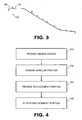
- FIG. 3 is a schematic diagram depicting another step of an exemplary embodiment of method.
- FIG. 4 is a flowchart depicting an embodiment of a method for repairing a gas turbine engine casing.
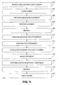
- FIG. 5 is a schematic diagram depicting another embodiment of a method for repairing a gas turbine engine casing.
- an annular portion of an engine casing is removed and replaced.
- attachment of the replacement is facilitated by welding, after which a heat treatment can be performed in order to reduce stresses in the vicinity of the repair site.
- engine casing 100 includes non-containment zones (e.g., non-containment zone 102) and containment zones (e.g., a containment zone 104). Specifically, each containment zone is located in a vicinity of corresponding rotating blades (e.g., blade 105) of a turbine that are positioned within the casing.
- the non-containment zone 102 is associated with a replacement portion 106 that includes a front flange 108 of the casing.
- the front flange is used to attach the casing to an adjacent casing.
- a front flange flange 110 of FIG. 2
- a front flange flange 110 of FIG. 2
- was previously attached to the case was considered unsuitable for continued use, such as by exhibiting severe cracking or wear, and was removed.
- removal of front flange 110 from case is accomplished by cutting the case along the cut plane 120.
- the cut plane is oriented perpendicular to the longitudinal axis 122 of the casing although other cut plane orientations can be used in other embodiments. Cutting can be accomplished in various manners, such as by machining, turning, milling, sawing, or laser cutting.
- the cut plane is located outside of a containment zone of the casing in this embodiment. However, in other embodiments, the cut plane may be associated with a containment zone.
- annular replacement component 130 is provided that includes replacement portion 106 and an optional trim portion 132.
- the trim portion is formed of excess material that can be trimmed to form an appropriate mating surface for engaging a corresponding surface of the casing 100.
- the trim portion can be suitably dimensioned for attachment to the casing using various techniques, such as using a technique similar to that use in removing the front flange (shown in FIG. 2 ). After the replacement component is trimmed, attachment to the casing 100 can be accomplished by using various techniques.
- an exemplary embodiment of a method for repairing a gas turbine engine casing includes providing an engine casing (block 150).
- an annular portion of the engine case is removed, and a replacement portion is provided (block 154).
- the portion removed is restricted to non-containment portion of the casing.
- the replacement portion is attached to the engine casing.
- FIG. 5 Another exemplary embodiment of a method for repairing a gas turbine engine casing is depicted in the flowchart of FIG. 5 .
- the method may be construed as beginning at block 200, in which an annular portion of a gas turbine engine casing is removed.
- the portion can be a front flange portion of a turbine casing.
- the remaining casing can be cleaned.
- a replacement component e.g., a forged replacement flange with a trim portion
- a hardness check is performed.
- the hardness should be at least approximately HRC36 (or equivalent). If it is determined that the hardness is adequate, the process may proceed to block 206, in which the replacement component is trimmed.
- the replacement component can be machined (and optionally cleaned) in order to provide appropriate mating tolerance for the attachment technique that is to be used for attaching the replacement portion to the casing.
- an inspection can be performed such as a fluorescent penetrant inspection, x-ray inspection and/or hardness inspection in order to identify any defects.
- material in a vicinity of the attachment can be prepared (such as by cleaning with a silicon carbide rag wheel or a stainless steel wire brush, for example) in order to prepare the mating surfaces for attachment.
- this can involve preparing an approximately one inch (25.4 mm) wide area adjacent to the cut line at the front face of the case and the corresponding mating surface of the replacement portion.
- Preparation also can include additional cleaning steps in some embodiments, such as by cleaning the surfaces with a solvent wipe method.
- the replacement portion is positioned for attachment. Notably, this can involve inspection to confirm that any gaps between the replacement portion and the casing do not exceed acceptable tolerances. If tolerances are met, the process may proceed to block 214, in which the replacement portion is attached to the casing, such as by welding, for example. In this regard, various welding techniques, such as electron beam welding (EBW), machine TiG welding and plasma arc welding can be used. Inspection and optional re-welding then can be performed such as depicted in block 216. Thereafter, such as depicted in block 218, stress relief/heat treatment can be performed in order to relieve internal stresses.
- ESW electron beam welding
- machine TiG welding machine TiG welding
- plasma arc welding plasma arc welding
- various inspections such as a hardness check, fluorescent penetrant inspection and/or x-ray inspection can be performed to insure completeness of the weld. Finishing then can be performed in block 222.
- the weld can be machine finished to ensure a smooth continuous surface with no undercuts. Final cleaning and inspection then can be performed.
- the replacement component and salvaged casing can be heat treated (e.g., solution heat treated) prior to welding in order to soften the materials for ease of welding and to potentially prevent rework.
- heat treated e.g., solution heat treated
Landscapes
- Engineering & Computer Science (AREA)
- Mechanical Engineering (AREA)
- General Engineering & Computer Science (AREA)
- Laser Beam Processing (AREA)
- Structures Of Non-Positive Displacement Pumps (AREA)
- Arc Welding In General (AREA)
Abstract
Description
- The disclosure generally relates to gas turbine engines.
- Gas turbine engine components typically experience harsh operating conditions such as high temperature cycling, which can result in thermal fatigue and other types of distress modes such as cracking or wear. Additionally, some engines are exposed to harsh environment conditions such as salt ingestion that can occur during transoceanic flights, for example. Due to these and other factors, gas turbine engine components can wear and/or become damaged. In this regard, repair of gas turbine engine components oftentimes involves dimensionally restoring the components.
- Methods for repairing gas turbine engine casings and repaired casings are provided. In this regard, an exemplary embodiment of a method for repairing a gas turbine engine casing comprises: removing an annular portion of the engine casing; and attaching an annular replacement portion to the engine casing.
- Another exemplary embodiment of a method comprises: providing a salvaged engine casing; removing an annular portion of the engine casing; providing a replacement component comprising excess material; trimming the excess material of the replacement component to form a replacement portion; and attaching the replacement portion to the engine casing.
- An exemplary embodiment of a repaired gas turbine engine casing comprises an annular replacement portion attached to the casing.
- Other systems, methods, features and/or advantages of this disclosure will be or may become apparent to one with skill in the art upon examination of the following drawings and detailed description. It is intended that all such additional systems, methods, features and/or advantages be included within this description and be within the scope of the present disclosure.
- Many aspects of the disclosure can be better understood with reference to the following drawings. The components in the drawings are not necessarily to scale. Moreover, in the drawings, like reference numerals designate corresponding parts throughout the several views.
-
FIG. 1 is a schematic diagram depicting a portion of a representative repaired engine casing. -
FIG. 2 is a schematic diagram depicting a step of an exemplary embodiment of a method for repairing a gas turbine engine casing. -
FIG. 3 is a schematic diagram depicting another step of an exemplary embodiment of method. -
FIG. 4 is a flowchart depicting an embodiment of a method for repairing a gas turbine engine casing. -
FIG. 5 is a schematic diagram depicting another embodiment of a method for repairing a gas turbine engine casing. - Methods for repairing gas turbine engine casings and repaired casings are provided, several exemplary embodiments of which will be described in detail. In some embodiments, an annular portion of an engine casing is removed and replaced. In some embodiments, attachment of the replacement is facilitated by welding, after which a heat treatment can be performed in order to reduce stresses in the vicinity of the repair site.
- An exemplary embodiment of a repaired engine casing is depicted schematically in
FIG. 1 . As shown inFIG. 1 ,engine casing 100 includes non-containment zones (e.g., non-containment zone 102) and containment zones (e.g., a containment zone 104). Specifically, each containment zone is located in a vicinity of corresponding rotating blades (e.g., blade 105) of a turbine that are positioned within the casing. In this embodiment, thenon-containment zone 102 is associated with areplacement portion 106 that includes afront flange 108 of the casing. The front flange is used to attach the casing to an adjacent casing. Notably, a front flange (flange 110 ofFIG. 2 ) that was previously attached to the case was considered unsuitable for continued use, such as by exhibiting severe cracking or wear, and was removed. - As shown in
FIG. 2 , removal offront flange 110 from case is accomplished by cutting the case along thecut plane 120. The cut plane is oriented perpendicular to thelongitudinal axis 122 of the casing although other cut plane orientations can be used in other embodiments. Cutting can be accomplished in various manners, such as by machining, turning, milling, sawing, or laser cutting. Notably, the cut plane is located outside of a containment zone of the casing in this embodiment. However, in other embodiments, the cut plane may be associated with a containment zone. - In
FIG. 3 ,annular replacement component 130 is provided that includesreplacement portion 106 and anoptional trim portion 132. The trim portion is formed of excess material that can be trimmed to form an appropriate mating surface for engaging a corresponding surface of thecasing 100. In this regard, the trim portion can be suitably dimensioned for attachment to the casing using various techniques, such as using a technique similar to that use in removing the front flange (shown inFIG. 2 ). After the replacement component is trimmed, attachment to thecasing 100 can be accomplished by using various techniques. - As shown in
FIG. 4 an exemplary embodiment of a method for repairing a gas turbine engine casing includes providing an engine casing (block 150). Inblock 152, an annular portion of the engine case is removed, and a replacement portion is provided (block 154). In some embodiments, the portion removed is restricted to non-containment portion of the casing. Thereafter, such as depicted inblock 156, the replacement portion is attached to the engine casing. - Another exemplary embodiment of a method for repairing a gas turbine engine casing is depicted in the flowchart of
FIG. 5 . As shown inFIG. 5 , the method may be construed as beginning atblock 200, in which an annular portion of a gas turbine engine casing is removed. By way of example, the portion can be a front flange portion of a turbine casing. Inblock 202, the remaining casing can be cleaned. - In
block 204, a replacement component (e.g., a forged replacement flange with a trim portion) is provided and a hardness check is performed. In some embodiments, such as when the casing is a precipitation-hardened nickel alloy turbine casing, the hardness should be at least approximately HRC36 (or equivalent). If it is determined that the hardness is adequate, the process may proceed toblock 206, in which the replacement component is trimmed. For instance, the replacement component can be machined (and optionally cleaned) in order to provide appropriate mating tolerance for the attachment technique that is to be used for attaching the replacement portion to the casing. Inblock 208, an inspection can be performed such as a fluorescent penetrant inspection, x-ray inspection and/or hardness inspection in order to identify any defects. - In
block 210, material in a vicinity of the attachment can be prepared (such as by cleaning with a silicon carbide rag wheel or a stainless steel wire brush, for example) in order to prepare the mating surfaces for attachment. In some embodiments, this can involve preparing an approximately one inch (25.4 mm) wide area adjacent to the cut line at the front face of the case and the corresponding mating surface of the replacement portion. Preparation also can include additional cleaning steps in some embodiments, such as by cleaning the surfaces with a solvent wipe method. - In
block 212, the replacement portion is positioned for attachment. Notably, this can involve inspection to confirm that any gaps between the replacement portion and the casing do not exceed acceptable tolerances. If tolerances are met, the process may proceed to block 214, in which the replacement portion is attached to the casing, such as by welding, for example. In this regard, various welding techniques, such as electron beam welding (EBW), machine TiG welding and plasma arc welding can be used. Inspection and optional re-welding then can be performed such as depicted inblock 216. Thereafter, such as depicted inblock 218, stress relief/heat treatment can be performed in order to relieve internal stresses. Inblock 220, various inspections, such as a hardness check, fluorescent penetrant inspection and/or x-ray inspection can be performed to insure completeness of the weld. Finishing then can be performed inblock 222. By way of example, the weld can be machine finished to ensure a smooth continuous surface with no undercuts. Final cleaning and inspection then can be performed. - In some embodiments, the replacement component and salvaged casing can be heat treated (e.g., solution heat treated) prior to welding in order to soften the materials for ease of welding and to potentially prevent rework. However, there is a risk of component/casing distortion during such heat treatment that may require appropriate fixturing to prevent distortion.
- It should be emphasized that the above-described embodiments are merely possible examples of implementations set forth for a clear understanding of the principles of this disclosure. Many variations and modifications may be made to the above-described embodiments without departing substantially from the principles of the disclosure. All such modifications and variations are intended to be included herein within the scope of this disclosure and protected by the accompanying claims.
Claims (14)
- A method for repairing gas turbine engine casing (100) comprising:removing an annular portion (110) of the engine casing (100); andattaching an annular replacement portion (106) to the engine casing (100).
- The method of claim 1, wherein attaching comprises:providing a replacement portion (106) with a trim portion (132) that is dimensioned to be trimmed prior to attachment; andtrimming the trim portion (132) such that gap tolerances between the replacement portion (106) and the casing (100) are provided.
- A method for repairing gas turbine engine casing (100) comprising:providing a salvaged engine casing (100);removing an annular portion (110) of the engine casing (100);providing a replacement component (130) comprising excess material;trimming the excess material of the replacement component (130) to form a replacement portion (106); andattaching the replacement portion (106) to the engine casing (100).
- The method of any preceding claim, wherein removing comprises cutting the casing (100) along a plane (120) perpendicular to a longitudinal axis (122) of the casing (100).
- The method of any preceding claim, wherein the portion (110) removed is a non-containment portion of the casing (100).
- The method of any preceding claim, wherein attaching comprises welding the replacement portion (106) to the engine casing (100).
- The method of claim 6, wherein welding the replacement portion (106) to the engine casing (100) is performed using at least one of: electron beam welding, machine TiG welding and plasma arc welding.
- The method of any preceding claim, further comprising performing at least one of the following:a stress relief/heat treatment before attaching the replacement portion (106) to the engine casing (100); anda stress relief/heat treatment after attaching the replacement portion (106) to the engine casing (100).
- The method of any preceding claim, wherein the casing (100) is a turbine casing.
- The method of any preceding claim, further comprising finishing the casing (100).
- A repaired gas turbine engine casing (100) comprising:an annular replacement portion (106) attached to the casing (100).
- The casing of claim 11, wherein the casing (100) is a turbine casing.
- The casing of claim 11 or 12, wherein:the casing (100) has a front portion and an aft portion; andthe front portion comprises the replacement portion (106).
- The casing of claim 13, wherein the replacement portion (106) includes a front flange.
Applications Claiming Priority (1)
| Application Number | Priority Date | Filing Date | Title |
|---|---|---|---|
| US11/853,924 US9765622B2 (en) | 2007-09-12 | 2007-09-12 | Methods for performing gas turbine engine casing repairs and repaired cases |
Publications (3)
| Publication Number | Publication Date |
|---|---|
| EP2039882A2 true EP2039882A2 (en) | 2009-03-25 |
| EP2039882A3 EP2039882A3 (en) | 2012-03-14 |
| EP2039882B1 EP2039882B1 (en) | 2018-10-31 |
Family
ID=40202136
Family Applications (1)
| Application Number | Title | Priority Date | Filing Date |
|---|---|---|---|
| EP08252957.9A Active EP2039882B1 (en) | 2007-09-12 | 2008-09-05 | Methods for performing gas turbine engine casing repairs |
Country Status (3)
| Country | Link |
|---|---|
| US (1) | US9765622B2 (en) |
| EP (1) | EP2039882B1 (en) |
| SG (1) | SG151157A1 (en) |
Cited By (3)
| Publication number | Priority date | Publication date | Assignee | Title |
|---|---|---|---|---|
| US20120328423A1 (en) * | 2011-06-20 | 2012-12-27 | Mitsubishi Heavy Industries, Ltd. | Gas turbine and repairing method of gas turbine |
| EP2472070A3 (en) * | 2010-12-30 | 2014-06-04 | Rolls-Royce Corporation | Methods of manufacturing a gas turbine engine case and corresponding case |
| WO2016038282A1 (en) * | 2014-09-11 | 2016-03-17 | Snecma | Method for repairing an upstream rail of a turbine engine turbine casing |
Families Citing this family (7)
| Publication number | Priority date | Publication date | Assignee | Title |
|---|---|---|---|---|
| US8770933B2 (en) | 2010-09-10 | 2014-07-08 | Honeywell International Inc. | Turbine nozzle assemblies and methods for repairing turbine nozzle assemblies |
| GB2510816B (en) * | 2013-02-12 | 2015-04-08 | Rolls Royce Plc | Material removal method |
| US20160076555A1 (en) * | 2014-09-12 | 2016-03-17 | Caterpillar Inc. | Remanufactured Center Housing and Method |
| DE102015203234B4 (en) * | 2015-02-24 | 2018-04-26 | MTU Aero Engines AG | Method for producing a component, namely a housing of a gas turbine and the corresponding component |
| CN106968988B (en) * | 2017-04-25 | 2019-02-26 | 西北工业大学 | An axially forward, radially inclined reverse vane angular slot processing casing |
| PL421648A1 (en) | 2017-05-19 | 2018-12-03 | General Electric Company | Removal of a kevlar wrapper from a fan housing |
| CN107116336B (en) * | 2017-06-16 | 2019-01-04 | 中国人民解放军第五七一九工厂 | A kind of aero-engine composite material casing restorative procedure |
Family Cites Families (23)
| Publication number | Priority date | Publication date | Assignee | Title |
|---|---|---|---|---|
| US5193257A (en) * | 1989-07-17 | 1993-03-16 | Dayton Power And Light Company | Boiler tube repair apparatus |
| WO1993022097A1 (en) | 1992-05-06 | 1993-11-11 | United Technologies Corporation | Heat treatment and repair of cobalt-base superalloy articles |
| DE19504655A1 (en) * | 1995-02-13 | 1996-08-14 | Abb Management Ag | Electrical synchronous machine with slip rings arranged outside the machine housing and method for their production |
| US6615470B2 (en) | 1997-12-15 | 2003-09-09 | General Electric Company | System and method for repairing cast articles |
| US6464128B1 (en) | 1999-05-28 | 2002-10-15 | General Electric Company | Braze repair of a gas turbine engine stationary shroud |
| US6531005B1 (en) | 2000-11-17 | 2003-03-11 | General Electric Co. | Heat treatment of weld repaired gas turbine engine components |
| US6426152B1 (en) | 2000-12-14 | 2002-07-30 | General Electric Company | Salvaged castings and methods of salvaging castings with defective cast cooling bumps |
| US6607114B2 (en) | 2001-10-12 | 2003-08-19 | General Electric Company | Weld fixture and method for repairing annular components |
| US6914210B2 (en) | 2002-10-30 | 2005-07-05 | General Electric Company | Method of repairing a stationary shroud of a gas turbine engine using plasma transferred arc welding |
| US6925810B2 (en) * | 2002-11-08 | 2005-08-09 | Honeywell International, Inc. | Gas turbine engine transition liner assembly and repair |
| US6892931B2 (en) * | 2002-12-27 | 2005-05-17 | General Electric Company | Methods for replacing portions of turbine shroud supports |
| FR2854198B1 (en) * | 2003-04-22 | 2005-06-24 | Snecma Services | PROCESS FOR REPLACING ABRADABLE ON THE BLOWER HOUSING OF A TURBOJETACTOR |
| US7146725B2 (en) | 2003-05-06 | 2006-12-12 | Siemens Power Generation, Inc. | Repair of combustion turbine components |
| US7371426B2 (en) | 2003-11-13 | 2008-05-13 | General Electric Company | Method for repairing components using environmental bond coatings and resultant repaired components |
| US7159755B2 (en) | 2004-02-05 | 2007-01-09 | General Electric Company | Method and apparatus for rebuilding gas turbine engines |
| US6969826B2 (en) | 2004-04-08 | 2005-11-29 | General Electric Company | Welding process |
| US7244320B2 (en) | 2004-06-01 | 2007-07-17 | United Technologies Corporation | Methods for repairing gas turbine engine components |
| FR2871399B1 (en) * | 2004-06-15 | 2006-09-22 | Snecma Moteurs Sa | PROCESS FOR REPAIRING A DAWN ELEMENT |
| US7546684B2 (en) * | 2004-07-27 | 2009-06-16 | General Electric Company | Method for repair and replacement of combustor liner panel |
| US7259350B2 (en) | 2004-08-26 | 2007-08-21 | United Technologies Corporation | Turbine component crack repair using cathodic arc and/or low pressure plasma spraying and HIP |
| US7185433B2 (en) | 2004-12-17 | 2007-03-06 | General Electric Company | Turbine nozzle segment and method of repairing same |
| US7029371B1 (en) * | 2005-06-17 | 2006-04-18 | Siemens Power Generation, Inc. | Jig for guiding a grinder |
| US20080216300A1 (en) | 2007-03-06 | 2008-09-11 | United Technologies Corporation | Splitter fairing repair |
-
2007
- 2007-09-12 US US11/853,924 patent/US9765622B2/en active Active
-
2008
- 2008-07-15 SG SG200805285-4A patent/SG151157A1/en unknown
- 2008-09-05 EP EP08252957.9A patent/EP2039882B1/en active Active
Cited By (8)
| Publication number | Priority date | Publication date | Assignee | Title |
|---|---|---|---|---|
| EP2472070A3 (en) * | 2010-12-30 | 2014-06-04 | Rolls-Royce Corporation | Methods of manufacturing a gas turbine engine case and corresponding case |
| US20120328423A1 (en) * | 2011-06-20 | 2012-12-27 | Mitsubishi Heavy Industries, Ltd. | Gas turbine and repairing method of gas turbine |
| US9435226B2 (en) * | 2011-06-20 | 2016-09-06 | Mitsubishi Hitachi Power Systems, Ltd. | Gas turbine and repairing method of gas turbine |
| WO2016038282A1 (en) * | 2014-09-11 | 2016-03-17 | Snecma | Method for repairing an upstream rail of a turbine engine turbine casing |
| FR3025734A1 (en) * | 2014-09-11 | 2016-03-18 | Snecma | PROCESS FOR REPAIRING A UPSTREAM RAIL OF A TURBINE ENGINE TURBINE CASE |
| CN107073622A (en) * | 2014-09-11 | 2017-08-18 | 赛峰航空器发动机 | The method of the upstream track of repairing turbine engine turbine case |
| US10759010B2 (en) | 2014-09-11 | 2020-09-01 | Safran Aircraft Engines | Method for repairing an upstream rail of a turbine engine turbine casing |
| US11707808B2 (en) | 2014-09-11 | 2023-07-25 | Safran Aircraft Engines | Method for repairing an upstream rail of a turbine engine turbine casing |
Also Published As
| Publication number | Publication date |
|---|---|
| EP2039882A3 (en) | 2012-03-14 |
| EP2039882B1 (en) | 2018-10-31 |
| US20090064479A1 (en) | 2009-03-12 |
| US9765622B2 (en) | 2017-09-19 |
| SG151157A1 (en) | 2009-04-30 |
Similar Documents
| Publication | Publication Date | Title |
|---|---|---|
| EP2039882B1 (en) | Methods for performing gas turbine engine casing repairs | |
| JP5322371B2 (en) | How to repair a disk with an integrated blade, test piece at the start and end of work | |
| US7009137B2 (en) | Laser powder fusion repair of Z-notches with nickel based superalloy powder | |
| EP1892374B2 (en) | Method of repairing shrouded turbine blades with cracks in the vicinity of the outer shroud notch | |
| US8153922B2 (en) | Insert weld repair | |
| US20060067830A1 (en) | Method to restore an airfoil leading edge | |
| EP1944120A2 (en) | Weld repair of metallic components | |
| EP1793962A2 (en) | Method to restore an airfoil leading edge | |
| US20070111119A1 (en) | Method for repairing gas turbine engine compressor components | |
| JP5072237B2 (en) | Method for mechanically characterizing metallic materials | |
| WO2013184401A1 (en) | Method of working an airfoil using elevated temperature cmt welding | |
| CN110712002A (en) | Method for restoring blade or guide vane platform | |
| US20050274701A1 (en) | Homogeneous welding via pre-heating for high strength superalloy joining and material deposition | |
| EP3372318B1 (en) | Narrow gap processing | |
| US7784180B2 (en) | Method and blade repair element for blisk repair or new blisk manufacture | |
| CN115635243B (en) | A method for replacing and repairing spoke-type air intake casing blades | |
| EP2151543A2 (en) | Repair methods for turbines involving conductive heat resistance welding | |
| US20080189946A1 (en) | Dimensional restoration of stator inner shrouds | |
| Zhao et al. | Remanufacturing of compressor blade by laser direct metal deposition and subsequent multi-axis milling | |
| EP1978346B1 (en) | Method for checking surface condition after cleaning process | |
| Crall et al. | Laser twist weld repair of compressor blisk airfoils |
Legal Events
| Date | Code | Title | Description |
|---|---|---|---|
| PUAI | Public reference made under article 153(3) epc to a published international application that has entered the european phase |
Free format text: ORIGINAL CODE: 0009012 |
|
| AK | Designated contracting states |
Kind code of ref document: A2 Designated state(s): AT BE BG CH CY CZ DE DK EE ES FI FR GB GR HR HU IE IS IT LI LT LU LV MC MT NL NO PL PT RO SE SI SK TR |
|
| AX | Request for extension of the european patent |
Extension state: AL BA MK RS |
|
| PUAL | Search report despatched |
Free format text: ORIGINAL CODE: 0009013 |
|
| AK | Designated contracting states |
Kind code of ref document: A3 Designated state(s): AT BE BG CH CY CZ DE DK EE ES FI FR GB GR HR HU IE IS IT LI LT LU LV MC MT NL NO PL PT RO SE SI SK TR |
|
| AX | Request for extension of the european patent |
Extension state: AL BA MK RS |
|
| RIC1 | Information provided on ipc code assigned before grant |
Ipc: B23P 6/00 20060101ALI20120207BHEP Ipc: F01D 5/00 20060101AFI20120207BHEP Ipc: F04D 29/52 20060101ALI20120207BHEP Ipc: F01D 25/24 20060101ALI20120207BHEP |
|
| 17P | Request for examination filed |
Effective date: 20120912 |
|
| AKX | Designation fees paid |
Designated state(s): DE GB IE |
|
| RAP1 | Party data changed (applicant data changed or rights of an application transferred) |
Owner name: UNITED TECHNOLOGIES CORPORATION |
|
| STAA | Information on the status of an ep patent application or granted ep patent |
Free format text: STATUS: EXAMINATION IS IN PROGRESS |
|
| 17Q | First examination report despatched |
Effective date: 20171030 |
|
| GRAP | Despatch of communication of intention to grant a patent |
Free format text: ORIGINAL CODE: EPIDOSNIGR1 |
|
| STAA | Information on the status of an ep patent application or granted ep patent |
Free format text: STATUS: GRANT OF PATENT IS INTENDED |
|
| INTG | Intention to grant announced |
Effective date: 20180508 |
|
| GRAS | Grant fee paid |
Free format text: ORIGINAL CODE: EPIDOSNIGR3 |
|
| GRAA | (expected) grant |
Free format text: ORIGINAL CODE: 0009210 |
|
| STAA | Information on the status of an ep patent application or granted ep patent |
Free format text: STATUS: THE PATENT HAS BEEN GRANTED |
|
| AK | Designated contracting states |
Kind code of ref document: B1 Designated state(s): DE GB IE |
|
| REG | Reference to a national code |
Ref country code: GB Ref legal event code: FG4D |
|
| REG | Reference to a national code |
Ref country code: DE Ref legal event code: R096 Ref document number: 602008057653 Country of ref document: DE |
|
| REG | Reference to a national code |
Ref country code: IE Ref legal event code: FG4D |
|
| REG | Reference to a national code |
Ref country code: DE Ref legal event code: R097 Ref document number: 602008057653 Country of ref document: DE |
|
| PLBE | No opposition filed within time limit |
Free format text: ORIGINAL CODE: 0009261 |
|
| STAA | Information on the status of an ep patent application or granted ep patent |
Free format text: STATUS: NO OPPOSITION FILED WITHIN TIME LIMIT |
|
| 26N | No opposition filed |
Effective date: 20190801 |
|
| PG25 | Lapsed in a contracting state [announced via postgrant information from national office to epo] |
Ref country code: IE Free format text: LAPSE BECAUSE OF NON-PAYMENT OF DUE FEES Effective date: 20190905 |
|
| REG | Reference to a national code |
Ref country code: DE Ref legal event code: R081 Ref document number: 602008057653 Country of ref document: DE Owner name: RAYTHEON TECHNOLOGIES CORPORATION (N.D.GES.D.S, US Free format text: FORMER OWNER: UNITED TECHNOLOGIES CORPORATION, FARMINGTON, CONN., US Ref country code: DE Ref legal event code: R081 Ref document number: 602008057653 Country of ref document: DE Owner name: RTX CORPORATION (N.D.GES.D. STAATES DELAWARE),, US Free format text: FORMER OWNER: UNITED TECHNOLOGIES CORPORATION, FARMINGTON, CONN., US |
|
| P01 | Opt-out of the competence of the unified patent court (upc) registered |
Effective date: 20230519 |
|
| PGFP | Annual fee paid to national office [announced via postgrant information from national office to epo] |
Ref country code: DE Payment date: 20250820 Year of fee payment: 18 |
|
| PGFP | Annual fee paid to national office [announced via postgrant information from national office to epo] |
Ref country code: GB Payment date: 20250822 Year of fee payment: 18 |
|
| REG | Reference to a national code |
Ref country code: DE Ref legal event code: R081 Ref document number: 602008057653 Country of ref document: DE Owner name: RTX CORPORATION (N.D.GES.D. STAATES DELAWARE),, US Free format text: FORMER OWNER: RAYTHEON TECHNOLOGIES CORPORATION (N.D.GES.D.STAATES DELAWARE), ARLINGTON, VA, US |