EP2039579A1 - Truck type transfer facilities - Google Patents
Truck type transfer facilities Download PDFInfo
- Publication number
- EP2039579A1 EP2039579A1 EP08722244A EP08722244A EP2039579A1 EP 2039579 A1 EP2039579 A1 EP 2039579A1 EP 08722244 A EP08722244 A EP 08722244A EP 08722244 A EP08722244 A EP 08722244A EP 2039579 A1 EP2039579 A1 EP 2039579A1
- Authority
- EP
- European Patent Office
- Prior art keywords
- elevating
- elevating guide
- carriage
- guide rails
- conveyance
- Prior art date
- Legal status (The legal status is an assumption and is not a legal conclusion. Google has not performed a legal analysis and makes no representation as to the accuracy of the status listed.)
- Granted
Links
Images








Classifications
-
- B—PERFORMING OPERATIONS; TRANSPORTING
- B61—RAILWAYS
- B61J—SHIFTING OR SHUNTING OF RAIL VEHICLES
- B61J1/00—Turntables; Traversers; Transporting rail vehicles on other rail vehicles or dollies
- B61J1/10—Traversers
-
- B—PERFORMING OPERATIONS; TRANSPORTING
- B61—RAILWAYS
- B61B—RAILWAY SYSTEMS; EQUIPMENT THEREFOR NOT OTHERWISE PROVIDED FOR
- B61B13/00—Other railway systems
- B61B13/04—Monorail systems
- B61B13/06—Saddle or like balanced type
-
- B—PERFORMING OPERATIONS; TRANSPORTING
- B65—CONVEYING; PACKING; STORING; HANDLING THIN OR FILAMENTARY MATERIAL
- B65G—TRANSPORT OR STORAGE DEVICES, e.g. CONVEYORS FOR LOADING OR TIPPING, SHOP CONVEYOR SYSTEMS OR PNEUMATIC TUBE CONVEYORS
- B65G35/00—Mechanical conveyors not otherwise provided for
- B65G35/06—Mechanical conveyors not otherwise provided for comprising a load-carrier moving along a path, e.g. a closed path, and adapted to be engaged by any one of a series of traction elements spaced along the path
-
- B—PERFORMING OPERATIONS; TRANSPORTING
- B65—CONVEYING; PACKING; STORING; HANDLING THIN OR FILAMENTARY MATERIAL
- B65G—TRANSPORT OR STORAGE DEVICES, e.g. CONVEYORS FOR LOADING OR TIPPING, SHOP CONVEYOR SYSTEMS OR PNEUMATIC TUBE CONVEYORS
- B65G39/00—Rollers, e.g. drive rollers, or arrangements thereof incorporated in roller-ways or other types of mechanical conveyors
- B65G39/02—Adaptations of individual rollers and supports therefor
- B65G39/09—Arrangements of bearing or sealing means
Definitions
- the present invention relates to a carriage-type conveyance system using a conveyance carriage which travels on guide rails laid on a floor surface along a conveyance path.
- a crossing aisle floor member is laid to be flush with the upper surfaces of the guide rails and slopes for eliminating level differences from the floor surface are formed on both ends of the crossing aisle floor member although patent documents disclosing this construction cannot be presented.
- An object of the present invention is to provide a carriage-type conveyance system which can solve the conventional problem described above, and a carriage-type conveyance system according to a first aspect which uses, shown with the reference numerals in parentheses of the embodiment described later, a conveyance path formed by guide rails (7a and 7b) laid on a floor surface and a conveyance carriage (1) which travels on the guide rails (7a and 7b), and is provided with an aisle crossing section (14) which an aisle (13) on the floor surface crosses in the conveyance path, includes a pit (15); elevating guide rails (16a and 16b), and elevating drive devices (19A and 19B), wherein the pit (15) is formed by digging down into the floor surface (6) of the aisle crossing section (14) and is covered by a floor member (18) laid to be flush with the floor surface (6), the elevating guide rails (16a and 16b) are disposed inside the pit (15) movably vertically parallel between a raised level at which they connect the guide rails (7a and 7b) before and after the pit (15
- the conveyance carriage (1) is provided with at least four guided portions (3a through 3d) at appropriate intervals in the traveling direction, and on the conveyance paths before and after the aisle crossing section (14), conveyance carriage guide rails (8) which engage with the guided portions (3a through 3d) are laid so that at least two of the guided portions (3a through 3d) always engage with the conveyance carriage guide rails (8) when the conveyance carriage (1) passes through the aisle crossing section (14).
- a carriage stopper (39a) and a switching means (46) are provided parallel, and the carriage stopper (39a) is provided on at least the upstream side of the conveyance carriage traveling direction of the aisle crossing section (14), and is freely switched between a working posture in which the carriage stopper stops the conveyance carriage (1) before the elevating guide rail (16a, 16b) and a nonworking posture inwhich it allows the conveyance carriage (1) to pass through, and the switching means (46) switches the carriage stopper (39a) into the working posture only when the elevating guide rail (16a, 16b) is at the lowered level in conjunction with the vertical movements of the elevating guide rail (16a, 16b).
- the elevating drive devices (19A and 19B) are constituted by elevating support means (20A and 20B) and drive means (21), and the elevating support means (20A and 20B) is disposed at least at two positions before and after the elevating guide rails (16a and 16b) in the longitudinal direction, and is constituted each by cam rails (23) provided on either a movable body (22) movable in the longitudinal direction of the corresponding elevating guide rail (16a, 16b) below the elevating guide rail (16a, 16b) or the elevating guide rail (16a, 16b), and a cam follower roller (24) provided on the other, and the drive means (21) is constructed so as to reciprocate the movable bodies (22) of the elevating support means (20A and 20B) in conjunction with each other.
- the elevating guide rail (16a, 16b) is provided with an elevating guide unit (33) parallel, and a pair of left and right cam follower rollers (24) are axially supported concentrically on both left and right sides of the elevating guide rail (16a, 16b), and the elevating guide unit (33) is provided at least two positions before and after in the longitudinal direction of the elevating guide rail (16a, 16b), and has a pair of left and right slide guides (36) sandwiching the elevating guide rail (16a, 16b), and each elevating support means (20A, 20B) is provided with elevating guide rollers (30) and elevating guide members (32), and the pair of elevating guide rollers (30) are axially supported on the left and right concentrically with the cam follower rollers (24) on the outer sides of the pair of left and right cam follower rollers (24), a pair of left and right elevating guide members (32) are provided parallel so that the pair of left and right guide rollers (30) engage with these movably vertically,
- the conveyance carriage can be made to smoothly travel at a predetermined level via the elevating guide rails raised to the raised level when the conveyance carriage passes through the aisle crossing section
- the elevating guide rails are lowered to the lowered level when the conveyance carriage does not travel on the aisle crossing section, and accordingly, a flat crossing aisle flush with the floor surface around it is formed by the floor member covering the pit and the upper surfaces of the elevating guide rails at the lowered level, so that a handcart, etc., can be safely moved on this crossing aisle without extra labor.
- the orientation of the conveyance carriage to pass through the crossing aisle can be reliably restricted and the conveyance carriage can be prevented from unexpectedly deviating from the conveyance path when passing through the crossing aisle.
- the elevating guide rails can be smoothly moved vertically parallel while movements and falling in the left and right lateral direction and movements in the longitudinal direction of the elevating guide rails are reliably prevented, and the cam follower rollers and the elevating guide rollers can be axially supported by a common support shaft, so that the number of parts can be reduced and the system can be constructed inexpensively.
- the reference numeral 1 denotes a conveyance carriage which is provided with two front and rear pairs of left and right wheels 2 on the bottom and four vertical axis rollers 3a through 3d axially supported at appropriate intervals on a straight line parallel to a traveling direction, and an elevating rack 5 at an upper central portion which is supported so as to be elevated by a crosslink mechanism 4.
- This elevating rack 5 can be elevated by various conventionally known methods such as a motor driving method in which the crosslink mechanism 4 is raised and lowered by a motor-driven screw mechanism or a cam rail method in which the elevating rack 5 is raised by pushing-up elevating cam follower rollers interlocked with rising and lowering movements of the crosslink mechanism 4 by cam rails laid on the floor surface side and the elevating rack 5 is lowered by gravity.
- a motor driving method in which the crosslink mechanism 4 is raised and lowered by a motor-driven screw mechanism
- a cam rail method in which the elevating rack 5 is raised by pushing-up elevating cam follower rollers interlocked with rising and lowering movements of the crosslink mechanism 4 by cam rails laid on the floor surface side and the elevating rack 5 is lowered by gravity.
- the four vertical axis rollers 3d through 3d arranged in series are disposed at positions near both front and rear ends and two intermediate positions of the conveyance carriage 1 on an imaginary straight line in the front and rear direction (traveling direction) adjacent to the inner side of left or right wheels 2.
- the traveling drive method for this conveyance carriage 1 is not especially limited, and for example, as shown by the imaginary lines in Fig. 1 and Fig. 3A , a frictional driving method can be used in which a frictional drive means 12 consisting of a frictional driving roller 9 and a backup roller 10 which sandwich the parallel left and right side surfaces 1a and 1b of the conveyance carriage 1 and a motor 11 which drives and rotates the frictional driving roller 9 is provided at positions at appropriate intervals on the conveyance path.
- a frictional drive means 12 consisting of a frictional driving roller 9 and a backup roller 10 which sandwich the parallel left and right side surfaces 1a and 1b of the conveyance carriage 1 and a motor 11 which drives and rotates the frictional driving roller 9 is provided at positions at appropriate intervals on the conveyance path.
- an aisle 13 is provided on the floor surface to cross the conveyance path.
- the guide rails 7a and 7b and the conveyance carriage guide rails 8 are not laid.
- the width of the crossing aisle 13 is shorter than the distance between two vertical axis rollers 3a and 3d on both ends among the four vertical axis rollers 3a through 3d arranged in series but are longer than the distance between the two middle vertical axis rollers 3b and 3c so that, when the conveyance carriage 1 passes through the aisle crossing section 14, fitting with play remaining of only one vertical axis roller 3a at the front end or one vertical axis roller 3d at the rear end among the four vertical axis rollers 3a through 3d arranged in series in the conveyance carriage guiding groove-shaped guide rails 8 is prevented, that is, at least two vertical axis rollers among the four vertical axis rollers 3a through 3d in series always fit with play remaining in either one of the conveyance carriage guiding groove-
- a pit 15 is provided by digging down into the floor surface 6, and inside this pit 15, elevating guide rails 16a and 16b which connect the guide rails 7a and 7b before and after the aisle crossing section 14 are provided.
- These elevating guide rails 16a and 16b are constructed so as to freely move vertically parallel between a raised level at which they connect the guide rails 7a and 7b and a lowered level at which the upper surfaces of the elevating guide rails 16a and 16b are flush with the floor surface 6 as shown in Fig. 2A , Fig. 3B, and Fig. 3C .
- a floor member 18 flush with the floor surface 6 is laid via a mount (not shown) while leaving apertures 17 in which the elevating guide rails 16a and 16b move vertically.
- the elevating drive device 19A of the elevating guide rail 16a and the elevating drive device 19B of the elevating guide rail 16b have the same structure, and Fig. 5 through Fig. 13 show the elevating drive device 19B of the elevating guide rail 16b.
- These elevating drive devices 19A and 19B include drive means 21 and elevating support means 20A and 20B disposed at two positions near both longitudinal ends of the elevating guide rails 16a and 16b.
- the elevating support means 20A and 20B have the same structure, and each includes a plate-shaped movable body 22 disposed below the elevating guide rail 16a, 16b, a pair of left and right cam rails 23 provided on the plate-shaped movable body 22, and two front and rear pairs of left and right cam follower rollers 24 placed on the cam rails 23 so as to roll freely. As shown in Fig. 13 and Fig.
- the plate-shaped movable body 22 is supported on the pair of left and right slide guide rails 26 on a substrate 25 laid on the bottom surface of the pit 15, movably in the longitudinal direction of the elevating guide rail 16a, 16b via slide blocks 27, and the pair of left and right cam rails 23 are disposed parallel to the elevating guide rail 16a, 16b on both left and right sides of the elevating guide rail 16a, 16b, and the pair of left and right cam follower rollers 24 are axially supported by a common support shaft 29 in a horizontal posture on both left and right sides of the bearing member 28 provided below the elevating guide rail 16a, 16b.
- elevating guide rollers 30 are axially supported concentrically by using the common support shaft 29 axially supporting the cam follower rollers 24, and a pair of left and right elevating guide members 32 having vertical slots 31 in which the elevating guide rollers 30 fit with play remaining so as to roll and move vertically are attached onto the substrate 25 parallel to the elevating guide rail 16a, 16b on the outer sides of the pair of left and right cam rails 23.
- elevating guide units 33 are provided. As shown in Fig. 14 and Fig. 15 , these elevating guide units 33 include slip members 35 attached to both left and right sides of the elevating guide rail 16a, 16b via an attaching member attached to the lower side of the elevating guide rail 16a, 16b, and a pair of left and right slide guide plates 36 attached onto the substrate 25 so as to sandwich movably vertically the elevating guide rail 16a, 16b via the pair of left and right slip members 35.
- the drive means 21 consists of, as shown in Fig. 4 , a cylinder unit 37 which is interposed between the plate-shaped movable body 22 and the substrate 25 of one elevating support means 20A and reciprocates the plate-shaped movable body 22 of the elevating support means 20A, and a joint rod 38 which interlocks and joins the plate-shaped movable body 22 of the elevating support means 20A and the plate-shaped movable body 22 of the other elevating support means 20B.
- the elevating support means 20A and 20B of one elevating drive device 19B are provided with carriage stoppers 39a and 39b parallel.
- mounts 40a and 40b for supporting the ends of the guide rails 7a and 7b adjacent to the elevating guide rails 16a and 16b are stood on the substrates 25, and the carriage stoppers 39a and 39b are axially supported on bearing members 41 attached to the mounts 40a and 40b by support shafts 42 in left and right horizontal postures, and are constructed so as to swing vertically only between a standup working posture (see Fig. 10 , Fig. 11 , and Fig.
- This switching means 46 consists of a cam follower roller 44 axially supported on the carriage stopper 39a, 39b via a projecting support shaft 43 in a left and right horizontal posture projecting to the side of the elevating guide rail 16b from the carriage stopper 39a, 39b, and an operating plate 45 which is attached to the side surface of the elevating guide rail 16a, 16b so as to switch the carriage stopper 39a, 39b from the standup working posture into the fallen-down nonworking posture via the cam follower roller 44 when the elevating guide rail 16b rises to the raised level.
- the elevating guide rails 16a and 16b are prevented from falling in the left and right lateral direction by sandwiching the portions near both ends in the longitudinal direction by elevating guide units 33, and are prevented from moving in the longitudinal direction and are allowed to move only vertically by fitting, with play remaining, the elevating guide rollers 30 in slots 31 of the elevating guide members 32 of the elevating support means 20A and 20B.
- the cam rails 23 are formed so that the elevating guide rails 16a and 16b supported by the cam rails 23 move vertically parallel via the cam follower rollers 24 while maintaining their horizontal postures by actuating the cylinder units 37 of the drive means 21 of the elevating drive devices 19A and 19B and moving forward and rearward the cam rails 23 of both front and rear elevating support means 20A and 20B synchronously via the plate-shaped movable bodies 22.
- the cam rail 23 is provided with a low-level horizontal support surface and a high level horizontal support surface for selectively supporting the cam follower roller 24, and according to the movements of the cam rails 23 of both front and rear elevating support means 20A and 20B, the cam follower rollers 24 on the sides of the elevating guide rails 16a and 16b shift from one to the other of the low-level horizontal support surfaces and the high-level horizontal support surfaces of the cam rails 23 simultaneously.
- the elevating guide rails 16a and 16b are lowered to the lowered level as shown in Fig. 2B , Fig. 3C , Fig. 7B , Fig. 10 , Fig. 11 , Fig. 13 , and Fig. 15 .
- the cam rails 23 of both front and rear elevating support means 20A and 20B of the elevating drive devices 19A and 19B are slid to the downstream side of the aisle crossing section 14 by the drive means 21 (cylinder units 37) and switched into a state that the low-level horizontal support surfaces of the cam rails 23 support the cam follower rollers 24.
- the elevating guide rails 16a and 16b lower from the raised level to the lowered level, and the upper surfaces of the elevating guide rails 16a and 16b become flush with the surface of the floor member 18 covering the pit 15, that is, the floor surface 6.
- the upper surface of the aisle crossing section 14 becomes a flat surface flush with the floor surface 6 of the crossing aisle 13, so that a handcart, etc., can be safely and smoothly moved on the crossing aisle 13.
- the conveyance carriage 1 is made to enter the aisle crossing section 14 by mistake in the state that the elevating guide rails 16a and 16b are lowered to the lowered level as described above, the forefront vertical axis roller 3a among the vertical axis rollers 3a through 3d of the conveyance carriage 1 is received by the carriage stopper 39a, 39b entering inside the terminal end of the conveyance carriage guiding groove-shaped guide rail 8 and the conveyance carriage 1 is prevented from entering the aisle crossing section 14.
- the traveling direction of the conveyance carriage 1 is limited to one direction, only the carriage stopper 39a on the upstream side of the aisle crossing section 14 may be provided.
- the drive means 21 (cylinder units 37) of the elevating drive devices 19A and 19B is actuated to slide the cam rails 23 to the upstream side of the aisle crossing section 14 as shown in Fig. 2A , Fig. 3B , Fig. 4 through Fig. 6 , Fig. 7A , Fig. 8 , Fig. 9 , Fig. 12 , and Fig. 14 via the plate-shaped movable bodies 22 of both front and rear elevating support means 20A and 20B, whereby the elevating guide rails 16a and 16b are raised to the raised level from the lowered level.
- the operating plates 45 of the switching means 46 of the carriage stoppers 39a and 39b rise together with the elevating guide rails 16a and 16b and push up the cam follower rollers 44 of the carriage stoppers 39a and 39b, so that the carriage stoppers 39a and 39b are switched into a fallen-down nonworking posture and withdraw downward from the movement path of the vertical axis rollers 3a through 3d of the conveyance carriage 1.
- the wheels 2 of the conveyance carriage 1 roll and move to the guide rails 7a and 7b on the downstream side of the aisle crossing section 14 through the elevating guide rails 16a and 16b at the raised level from the guide rails 7a and 7b on the upstream side of the aisle crossing section 14, and accordingly, the conveyance carriage 1 can pass through the aisle crossing section 14 without problems.
- the frictional drive means 12 is disposed front and rear adjacent to the aisle crossing section 14 so that the conveyance carriage 1 to be sent into the aisle crossing section 14 by the frictional drive means 12 on the upstream side of the aisle crossing section 14 is propelled successively by the frictional drive means 12 on the downstream side of the aisle crossing section 14 before separating from the frictional drive means 12 on the upstream side.
- the crossing aisle 13 Before the aisle crossing section 14, by providing the frictional drive means 12 which can temporarily stop the traveling conveyance carriage 1 and send it out to the aisle crossing section 14 at an arbitrary timing, the crossing aisle 13 can be used by temporarily stopping the conveyance carriage 1 before the aisle crossing section 14 and lowering the elevating guide rails 16a and 16b to the lowered level only when a vehicle, etc. , passes through the crossing aisle 13.
- a wide pit 15 covering the entire aisle crossing section 14 is provided, however, it is also allowed that two narrow and long pits for housing only the elevating guide rails 16a and 16b and the elevating drive devices 19A and 19B separately are formed. It is also allowed that the cam follower rollers 24 are axially supported on the plate-shaped movable bodies 22 and the cam rails 23 are laid below the elevating guide rails 16a and 16b.
- the carriage-type conveyance system according to the present invention can be used as a car body conveyance system in a car assembly line for attaching various parts to a car body while conveying the car body.
Landscapes
- Engineering & Computer Science (AREA)
- Mechanical Engineering (AREA)
- Transportation (AREA)
- Platform Screen Doors And Railroad Systems (AREA)
- Intermediate Stations On Conveyors (AREA)
- Machines For Laying And Maintaining Railways (AREA)
- Loading Or Unloading Of Vehicles (AREA)
- Structures Of Non-Positive Displacement Pumps (AREA)
- Non-Positive Displacement Air Blowers (AREA)
- Conveying And Assembling Of Building Elements In Situ (AREA)
Abstract
Description
- The present invention relates to a carriage-type conveyance system using a conveyance carriage which travels on guide rails laid on a floor surface along a conveyance path.
- In such a carriage-type conveyance system, when a floor surface aisle crossing section is included in the conveyance path, generally, to allow a vehicle, etc. , traveling on the floor surface aisle crossing section to safely and easily get over the guide rails on the conveyance path side, a crossing aisle floor member is laid to be flush with the upper surfaces of the guide rails and slopes for eliminating level differences from the floor surface are formed on both ends of the crossing aisle floor member although patent documents disclosing this construction cannot be presented.
- As described above, in the conventional construction in which a crossing aisle floor member having slopes on both ends is laid on the floor surface, not only is extra labor required to move a handcart or the like on the crossing aisle but also the safety is lowered in comparison with a flat floor surface on which no guide rails are laid.
- An object of the present invention is to provide a carriage-type conveyance system which can solve the conventional problem described above, and a carriage-type conveyance system according to a first aspect which uses, shown with the reference numerals in parentheses of the embodiment described later, a conveyance path formed by guide rails (7a and 7b) laid on a floor surface and a conveyance carriage (1) which travels on the guide rails (7a and 7b), and is provided with an aisle crossing section (14) which an aisle (13) on the floor surface crosses in the conveyance path, includes a pit (15); elevating guide rails (16a and 16b), and elevating drive devices (19A and 19B), wherein the pit (15) is formed by digging down into the floor surface (6) of the aisle crossing section (14) and is covered by a floor member (18) laid to be flush with the floor surface (6), the elevating guide rails (16a and 16b) are disposed inside the pit (15) movably vertically parallel between a raised level at which they connect the guide rails (7a and 7b) before and after the pit (15) and a lowered level at which their upper surfaces are flush with the floor surface (6), and the elevating drive devices (19A and 19B) elevate the elevating guide rails (16a and 16b) between the raised level and the lowered level, and in the floor member (18), elevating apertures (17) for the elevating guide rails (16a and 16b) are made.
- To carry out the present invention constructed as described above, in detail, as described in a second aspect, it is possible that the conveyance carriage (1) is provided with at least four guided portions (3a through 3d) at appropriate intervals in the traveling direction, and on the conveyance paths before and after the aisle crossing section (14), conveyance carriage guide rails (8) which engage with the guided portions (3a through 3d) are laid so that at least two of the guided portions (3a through 3d) always engage with the conveyance carriage guide rails (8) when the conveyance carriage (1) passes through the aisle crossing section (14).
- As described in a third aspect, in the conveyance path, a carriage stopper (39a) and a switching means (46) are provided parallel, and the carriage stopper (39a) is provided on at least the upstream side of the conveyance carriage traveling direction of the aisle crossing section (14), and is freely switched between a working posture in which the carriage stopper stops the conveyance carriage (1) before the elevating guide rail (16a, 16b) and a nonworking posture inwhich it allows the conveyance carriage (1) to pass through, and the switching means (46) switches the carriage stopper (39a) into the working posture only when the elevating guide rail (16a, 16b) is at the lowered level in conjunction with the vertical movements of the elevating guide rail (16a, 16b).
- Further, as described in a fourth aspect, it is possible that the elevating drive devices (19A and 19B) are constituted by elevating support means (20A and 20B) and drive means (21), and the elevating support means (20A and 20B) is disposed at least at two positions before and after the elevating guide rails (16a and 16b) in the longitudinal direction, and is constituted each by cam rails (23) provided on either a movable body (22) movable in the longitudinal direction of the corresponding elevating guide rail (16a, 16b) below the elevating guide rail (16a, 16b) or the elevating guide rail (16a, 16b), and a cam follower roller (24) provided on the other, and the drive means (21) is constructed so as to reciprocate the movable bodies (22) of the elevating support means (20A and 20B) in conjunction with each other. In this case, as described in a fifth aspect, the elevating guide rail (16a, 16b) is provided with an elevating guide unit (33) parallel, and a pair of left and right cam follower rollers (24) are axially supported concentrically on both left and right sides of the elevating guide rail (16a, 16b), and the elevating guide unit (33) is provided at least two positions before and after in the longitudinal direction of the elevating guide rail (16a, 16b), and has a pair of left and right slide guides (36) sandwiching the elevating guide rail (16a, 16b), and each elevating support means (20A, 20B) is provided with elevating guide rollers (30) and elevating guide members (32), and the pair of elevating guide rollers (30) are axially supported on the left and right concentrically with the cam follower rollers (24) on the outer sides of the pair of left and right cam follower rollers (24), a pair of left and right elevating guide members (32) are provided parallel so that the pair of left and right guide rollers (30) engage with these movably vertically, and the movable body (22) is disposed between the pair of left and right elevating guide members (32), and on the movable body (22), a pair of left and right cam rails (23) which support the pair of left and right cam follower rollers (24), respectively, are laid.
- According to the carriage-type conveyance system of the present invention described in the first aspect, although the conveyance carriage can be made to smoothly travel at a predetermined level via the elevating guide rails raised to the raised level when the conveyance carriage passes through the aisle crossing section, the elevating guide rails are lowered to the lowered level when the conveyance carriage does not travel on the aisle crossing section, and accordingly, a flat crossing aisle flush with the floor surface around it is formed by the floor member covering the pit and the upper surfaces of the elevating guide rails at the lowered level, so that a handcart, etc., can be safely moved on this crossing aisle without extra labor.
- According to the construction described in the second aspect, even without using flanged wheels that engage with guide rails as wheels of the conveyance carriage, the orientation of the conveyance carriage to pass through the crossing aisle can be reliably restricted and the conveyance carriage can be prevented from unexpectedly deviating from the conveyance path when passing through the crossing aisle.
- According to the construction described in the third aspect, there is no possibility that the conveyance carriage is made to enter the aisle crossing section by mistake in the state that the elevating guide rails disposed on the aisle crossing section are lowered to the lowered level, so that the safety can be increased.
- Further, according to the construction described in the fourth aspect, it is only required that below the elevating guide rails lowered to the lowered level, a space which allows the movable bodies having cam rails or cam follower rollers to move in the longitudinal direction of the elevating guide rails is secured, so that the depth of the pit that must be formed by digging down into the floor surface at the aisle crossing section can be made comparatively shallow. In this case, according to the construction described in the fifth aspect, the elevating guide rails can be smoothly moved vertically parallel while movements and falling in the left and right lateral direction and movements in the longitudinal direction of the elevating guide rails are reliably prevented, and the cam follower rollers and the elevating guide rollers can be axially supported by a common support shaft, so that the number of parts can be reduced and the system can be constructed inexpensively.
-
-
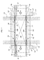
Fig. 1 is a schematic plan view showing an entire construction of an aisle crossing section; -
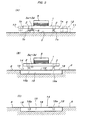
Fig. 2A is a schematic longitudinal sectional side view showing a state when the conveyance carriage passes through the aisle crossing section, andFig. 2B is a schematic longitudinal sectional side view showing a state when a crossing aisle is used; -
Fig. 3A is a schematic front view showing a conveyance carriage when traveling on a conveyance path,Fig. 3B is a schematic longitudinal sectional front view showing the conveyance carriage when traveling on the aisle crossing section, andFig. 3C is a schematic longitudinal sectional front view showing a state when the crossing aisle is used; -
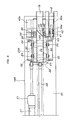
Fig. 4 is a plan view showing an elevating guide rail at a raised level and an elevating drive device for the elevating guide rail; -
Fig. 5 is an enlarged plan view of a main portion ofFig. 4 ; -
Fig. 6 is an enlarged plan view of another main portion ofFig. 4 ; -
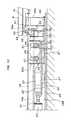
Fig. 7A is a side view of a main portion ofFig. 4 , andFig. 7B is a side view of the main portion in a state that the elevating guide rails are switched to the lowered level; -
Fig. 8 is an enlarged side view of a main portion ofFig. 7A ; -
Fig. 9 is an enlarged side view of another main portion ofFig. 7A ; -
Fig. 10 is an enlarged side view of a main portion ofFig. 7B ; -
Fig. 11 is an enlarged side view of another main portion ofFig. 7B ; -
Fig. 12 is a longitudinal sectional front view of a main portion when the elevating guide rails are at the raised level; -
Fig. 13 is a longitudinal sectional front view of the main portion when the elevating guide rails are at the lowered level; -
Fig. 14 is a longitudinal sectional front view of the main portion when the elevating guide rails are at the raised level and a carriage stopper is in a fallen-down nonworking posture; and -
Fig. 15 is a longitudinal sectional front view of the main portion when the elevating guide rails are at the lowered level and the carriage stopper is in a standup working posture. -
- 1:
- conveyance carriage
- 2:
- wheel
- 3a-3d:
- vertical axis roller
- 6:
- floor surface
- 7a, 7b:
- conveyance carriage supporting guide rail
- 8:
- conveyance carriage guiding groove-shaped guide rail
- 12:
- frictional driving means
- 13:
- floor surface aisle
- 14:
- aisle crossing section
- 15:
- pit
- 16a, 16b:
- elevating guide rail
- 17:
- aperture
- 18:
- floor member
- 19A, 19B:
- elevating drive device
- 20A, 20B:
- elevating support means
- 21:
- drive means
- 22:
- plate-shaped movable body
- 23:
- cam rail
- 24, 44:
- cam follower roller
- 25:
- substrate
- 26:
- slide guide rail
- 27:
- slide block
- 28, 41:
- bearing member
- 29,
- support shaft
- 30:
- elevating guide roller
- 31:
- slot
- 32:
- elevating guide member
- 33: 42:
- elevating guide unit
- 35:
- slip member
- 36:
- slide guide plate
- 37:
- cylinder unit
- 38:
- joint rod
- 39a, 39b:
- carriage stopper
- 40a, 40b:
- mount
- 45:
- operating plate
- 46:
- switching means
- Hereinafter, a detailed embodiment of the present invention will be described with reference to the accompanying drawings. In
Fig. 1 through Figs. 3 , thereference numeral 1 denotes a conveyance carriage which is provided with two front and rear pairs of left andright wheels 2 on the bottom and fourvertical axis rollers 3a through 3d axially supported at appropriate intervals on a straight line parallel to a traveling direction, and an elevatingrack 5 at an upper central portion which is supported so as to be elevated by acrosslink mechanism 4. This elevatingrack 5 can be elevated by various conventionally known methods such as a motor driving method in which thecrosslink mechanism 4 is raised and lowered by a motor-driven screw mechanism or a cam rail method in which the elevatingrack 5 is raised by pushing-up elevating cam follower rollers interlocked with rising and lowering movements of thecrosslink mechanism 4 by cam rails laid on the floor surface side and the elevatingrack 5 is lowered by gravity. - On the traveling path of the
conveyance carriage 1, that is, on thefloor surface 6 as the conveyance path, a pair of left andright guide rails support wheels 2 so as to allow these to roll freely, and conveyance carriage guiding groove-shapedguide rails 8 consisting of a pair of left and right rail members in which fourvertical axis rollers 3a through 3d arranged in series fit with play remaining are laid. The fourvertical axis rollers 3d through 3d arranged in series are disposed at positions near both front and rear ends and two intermediate positions of theconveyance carriage 1 on an imaginary straight line in the front and rear direction (traveling direction) adjacent to the inner side of left orright wheels 2. The traveling drive method for thisconveyance carriage 1 is not especially limited, and for example, as shown by the imaginary lines inFig. 1 andFig. 3A , a frictional driving method can be used in which a frictional drive means 12 consisting of africtional driving roller 9 and abackup roller 10 which sandwich the parallel left and right side surfaces 1a and 1b of theconveyance carriage 1 and amotor 11 which drives and rotates thefrictional driving roller 9 is provided at positions at appropriate intervals on the conveyance path. - In the conveyance path of the
conveyance carriage 1, anaisle 13 is provided on the floor surface to cross the conveyance path. On thisaisle crossing section 14 in the conveyance path, theguide rails carriage guide rails 8 are not laid. The width of the crossingaisle 13 is shorter than the distance between twovertical axis rollers vertical axis rollers 3a through 3d arranged in series but are longer than the distance between the two middlevertical axis rollers conveyance carriage 1 passes through theaisle crossing section 14, fitting with play remaining of only onevertical axis roller 3a at the front end or onevertical axis roller 3d at the rear end among the fourvertical axis rollers 3a through 3d arranged in series in the conveyance carriage guiding groove-shapedguide rails 8 is prevented, that is, at least two vertical axis rollers among the fourvertical axis rollers 3a through 3d in series always fit with play remaining in either one of the conveyance carriage guiding groove-shapedguide rails 8 before and after theaisle crossing section 14 or fit with play remaining across both conveyance carriage guiding groove-shapedguide rails 8 before and after theaisle crossing section 14. - At the
aisle crossing section 14 in the conveyance path of theconveyance carriage 1, apit 15 is provided by digging down into thefloor surface 6, and inside thispit 15, elevatingguide rails guide rails aisle crossing section 14 are provided. These elevatingguide rails guide rails guide rails floor surface 6 as shown inFig. 2A ,Fig. 3B, and Fig. 3C . Over thepit 15, afloor member 18 flush with thefloor surface 6 is laid via a mount (not shown) while leavingapertures 17 in which the elevatingguide rails - Hereinafter, an embodiment of the elevating drive device of the elevating
guide rail Fig. 4 through Fig. 13 . The elevatingdrive device 19A of the elevatingguide rail 16a and the elevatingdrive device 19B of the elevatingguide rail 16b have the same structure, andFig. 5 through Fig. 13 show the elevatingdrive device 19B of the elevatingguide rail 16b. These elevatingdrive devices guide rails movable body 22 disposed below the elevatingguide rail movable body 22, and two front and rear pairs of left and rightcam follower rollers 24 placed on the cam rails 23 so as to roll freely. As shown inFig. 13 andFig. 14 , the plate-shapedmovable body 22 is supported on the pair of left and rightslide guide rails 26 on asubstrate 25 laid on the bottom surface of thepit 15, movably in the longitudinal direction of the elevatingguide rail guide rail guide rail cam follower rollers 24 are axially supported by acommon support shaft 29 in a horizontal posture on both left and right sides of the bearingmember 28 provided below the elevatingguide rail - On the outer sides of the pair of left and right
cam follower rollers 24, elevatingguide rollers 30 are axially supported concentrically by using thecommon support shaft 29 axially supporting thecam follower rollers 24, and a pair of left and right elevatingguide members 32 havingvertical slots 31 in which the elevatingguide rollers 30 fit with play remaining so as to roll and move vertically are attached onto thesubstrate 25 parallel to the elevatingguide rail - Parallel to the respective elevating support means 20A and 20B, elevating
guide units 33 are provided. As shown inFig. 14 and Fig. 15 , these elevatingguide units 33 includeslip members 35 attached to both left and right sides of the elevatingguide rail guide rail slide guide plates 36 attached onto thesubstrate 25 so as to sandwich movably vertically the elevatingguide rail right slip members 35. - The drive means 21 consists of, as shown in
Fig. 4 , acylinder unit 37 which is interposed between the plate-shapedmovable body 22 and thesubstrate 25 of one elevating support means 20A and reciprocates the plate-shapedmovable body 22 of the elevating support means 20A, and ajoint rod 38 which interlocks and joins the plate-shapedmovable body 22 of the elevating support means 20A and the plate-shapedmovable body 22 of the other elevating support means 20B. - As shown in
Fig. 4 , the elevating support means 20A and 20B of one elevatingdrive device 19B are provided withcarriage stoppers drive device Fig. 8 through Fig. 11 , mounts 40a and 40b for supporting the ends of theguide rails guide rails substrates 25, and thecarriage stoppers members 41 attached to themounts support shafts 42 in left and right horizontal postures, and are constructed so as to swing vertically only between a standup working posture (seeFig. 10 ,Fig. 11 , andFig. 15 ) in contact with thevertical axis roller 3a (or 3d) moving within the conveyance carriage guiding groove-shapedguide rails 8 parallel to theguide rail 7b and a fallen-down nonworking posture that is fallen in a direction apart from theaisle crossing section 14 with respect to the standup working posture and allows thevertical axis rollers 3a through 3d to pass through (seeFig. 8 ,Fig. 9 , andFig. 14 ), and are urged into the standup working posture by gravity or a spring force. Further, as shown inFig. 14 and Fig. 15 , parallel to thesecarriage stoppers cam follower roller 44 axially supported on thecarriage stopper support shaft 43 in a left and right horizontal posture projecting to the side of the elevatingguide rail 16b from thecarriage stopper operating plate 45 which is attached to the side surface of the elevatingguide rail carriage stopper cam follower roller 44 when the elevatingguide rail 16b rises to the raised level. - In the above-described construction, the elevating
guide rails guide units 33, and are prevented from moving in the longitudinal direction and are allowed to move only vertically by fitting, with play remaining, the elevatingguide rollers 30 inslots 31 of the elevatingguide members 32 of the elevating support means 20A and 20B. The cam rails 23 are formed so that the elevatingguide rails cam follower rollers 24 while maintaining their horizontal postures by actuating thecylinder units 37 of the drive means 21 of the elevatingdrive devices movable bodies 22. Specifically, thecam rail 23 is provided with a low-level horizontal support surface and a high level horizontal support surface for selectively supporting thecam follower roller 24, and according to the movements of the cam rails 23 of both front and rear elevating support means 20A and 20B, thecam follower rollers 24 on the sides of the elevatingguide rails - Hereinafter, a usage will be described. Until the
conveyance carriage 1 traveling on the conveyance path approaches theaisle crossing section 14, the elevatingguide rails Fig. 2B ,Fig. 3C ,Fig. 7B ,Fig. 10 ,Fig. 11 ,Fig. 13 , andFig. 15 . Specifically, the cam rails 23 of both front and rear elevating support means 20A and 20B of the elevatingdrive devices aisle crossing section 14 by the drive means 21 (cylinder units 37) and switched into a state that the low-level horizontal support surfaces of the cam rails 23 support thecam follower rollers 24. As a result, the elevatingguide rails guide rails floor member 18 covering thepit 15, that is, thefloor surface 6. In this state, the upper surface of theaisle crossing section 14 becomes a flat surface flush with thefloor surface 6 of the crossingaisle 13, so that a handcart, etc., can be safely and smoothly moved on the crossingaisle 13. - In the state that the elevating
guide rails Fig. 10 ,Fig. 11 , andFig. 15 , the operatingplates 45 of the switching means 46 of thecarriage stoppers guide rails cam follower rollers 44 of thecarriage stoppers carriage stoppers conveyance carriage 1 is made to enter theaisle crossing section 14 by mistake in the state that the elevatingguide rails vertical axis roller 3a among thevertical axis rollers 3a through 3d of theconveyance carriage 1 is received by thecarriage stopper guide rail 8 and theconveyance carriage 1 is prevented from entering theaisle crossing section 14. When the traveling direction of theconveyance carriage 1 is limited to one direction, only thecarriage stopper 39a on the upstream side of theaisle crossing section 14 may be provided. - When the
conveyance carriage 1 traveling reaches a point at a predetermined distance to theaisle crossing section 14, the drive means 21 (cylinder units 37) of the elevatingdrive devices aisle crossing section 14 as shown inFig. 2A ,Fig. 3B ,Fig. 4 through Fig. 6 ,Fig. 7A ,Fig. 8 ,Fig. 9 ,Fig. 12 , andFig. 14 via the plate-shapedmovable bodies 22 of both front and rear elevating support means 20A and 20B, whereby the elevatingguide rails cam follower rollers 24. As a result, the elevatingguide rails apertures 17 of thefloor member 18 covering thepit 15 connect theguide rails aisle crossing section 14 at the same level, and simultaneously, as shown inFig. 8 ,Fig. 9 , andFig. 14 , the operatingplates 45 of the switching means 46 of thecarriage stoppers guide rails cam follower rollers 44 of thecarriage stoppers carriage stoppers vertical axis rollers 3a through 3d of theconveyance carriage 1. Therefore, thewheels 2 of theconveyance carriage 1 roll and move to theguide rails aisle crossing section 14 through the elevatingguide rails guide rails aisle crossing section 14, and accordingly, theconveyance carriage 1 can pass through theaisle crossing section 14 without problems. At this time, as described above, at least two vertical axis rollers among the fourvertical axis rollers 3a through 3d of theconveyance carriage 1 always fits, with play remaining, in the conveyance carriage guiding groove-shapedguide rails 8 before and after theaisle crossing section 14 when moving, so that theconveyance carriage 1 passing through theaisle crossing section 14 reliably travels straight, and there is no possibility that the orientation of theconveyance carriage 1 unexpectedly changes during passing through theaisle crossing section 14 and thewheels 2 come out of and fall off the elevatingguide rails guide rails aisle crossing section 14 and thevertical axis rollers 3a through 3d do not fit in the conveyance carriage guiding groove-shapedguide rail 8 on the downstream side of theaisle crossing section 14 and come out of it. - When the
conveyance carriage 1 is a type that is propelled by the frictional driving means 12, as shown by the imaginary lines inFig. 1 , the frictional drive means 12 is disposed front and rear adjacent to theaisle crossing section 14 so that theconveyance carriage 1 to be sent into theaisle crossing section 14 by the frictional drive means 12 on the upstream side of theaisle crossing section 14 is propelled successively by the frictional drive means 12 on the downstream side of theaisle crossing section 14 before separating from the frictional drive means 12 on the upstream side. Before theaisle crossing section 14, by providing the frictional drive means 12 which can temporarily stop the travelingconveyance carriage 1 and send it out to theaisle crossing section 14 at an arbitrary timing, the crossingaisle 13 can be used by temporarily stopping theconveyance carriage 1 before theaisle crossing section 14 and lowering the elevatingguide rails aisle 13. - In the illustrated embodiment, a
wide pit 15 covering the entireaisle crossing section 14 is provided, however, it is also allowed that two narrow and long pits for housing only the elevatingguide rails drive devices cam follower rollers 24 are axially supported on the plate-shapedmovable bodies 22 and the cam rails 23 are laid below the elevatingguide rails - The carriage-type conveyance system according to the present invention can be used as a car body conveyance system in a car assembly line for attaching various parts to a car body while conveying the car body.
Claims (5)
- A carriage-type conveyance system using a conveyance path formed by guide rails (7a and 7b) laid on a floor surface and a conveyance carriage (1) which travels on the guide rails (7a and 7b), and is provided with an aisle crossing section (14) which an aisle (13) on the floor surface crosses in the conveyance path, comprising: a pit (15); elevating guide rails (16a and 16b), and elevating drive devices (19A and 19B), wherein
the pit (15) is formed by digging down into the floor surface (6) of the aisle crossing section (14) and is covered by a floor member (18) laid to be flush with the floor surface (6),
the elevating guide rails (16a and 16b) are disposed inside the pit (15) movably vertically parallel between a raised level at which they connect the guide rails (7a and 7b) before and after the pit (15) and a lowered level at which their upper surfaces are flush with the floor surface (6), and
the elevating drive devices (19A and 19B) elevate the elevating guide rails (16a and 16b) between the raised level and the lowered level, where
elevating apertures (17) for the elevating guide rails (16a and 16b) are made in the floor member (18). - The carriage-type conveyance system according to Claim 1, wherein
the conveyance carriage (1) is provided with at least four guided portions (3a through 3d) at appropriate intervals in the traveling direction,
on the conveyance paths before and after the aisle crossing section (14), conveyance carriage guide rails (8) which engage with the guided portions (3a through 3d) are laid so that
at least two of the guided portions (3a through 3d) always engage with the conveyance carriage guide rails (8) when the conveyance carriage (1) passes through the aisle crossing section (14). - The carriage-type conveyance system according to Claim 1, wherein
in the conveyance path, a carriage stopper (39a) and a switching means (46) are provided parallel, where
the carriage stopper (39a) is provided on at least the upstream side of the conveyance carriage traveling direction of the aisle crossing section (14), and is freely switched between a working posture in which the carriage stopper stops the conveyance carriage (1) before the elevating guide rail (16a, 16b) and a nonworking posture in which it allows the conveyance carriage (1) to pass through, and
the switchingmeans (46) switches the carriage stopper (39a) into the working posture only when the elevating guide rail (16a, 16b) is at the lowered level in conjunction with the vertical movements of the elevating guide rail (16a, 16b). - The carriage-type conveyance system according to Claim 1, wherein
the elevating drive devices (19A and 19B) are constituted by elevating support means (20A and 20B) and drive means (21), where
the elevating support means (20A and 20B) is disposed at least at two positions before and after the elevating guide rails (16a and 16b) in the longitudinal direction, and is constituted each by cam rails (23) provided on either a movable body (22) movable in the longitudinal direction of the corresponding elevating guide rail (16a, 16b) below the elevating guide rail (16a, 16b) or the elevating guide rail (16a, 16b), and a cam follower roller (24) provided on the other, and
the drive means (21) is constructed so as to reciprocate the movable bodies (22) of the elevating support means (20A and 20B) in conjunction with each other. - The carriage-type conveyance system according to Claim 4, wherein
the elevating guide rail (16a, 16b) is provided with an elevating guide unit (33) parallel, and
a pair of left and right cam follower rollers (24) are axially supported concentrically on both left and right sides of the elevating guide rail (16a, 16b), where
the elevating guide unit (33) is provided at least two positions before and after in the longitudinal direction of the elevating guide rail (16a, 16b), and has a pair of left and right slide guides (36) sandwiching the elevating guide rail (16a, 16b), and
each elevating support means (20A, 20B) is provided with elevating guide rollers (30) and elevating guide members (32), where
the pair of elevating guide rollers (30) are axially supported on the left and right concentrically with the cam follower rollers (24) on the outer sides of the pair of left and right cam follower rollers (24),
the pair of left and right elevating guide members (32) are provided parallel so that the pair of left and right guide rollers (30) engage with these movably vertically, and
the movable body (22) is disposed between the pair of left and right elevating guide members (32), and
on the movable body (22), a pair of left and right cam rails (23) which support the pair of left and right cam follower rollers (24), respectively, are laid.
Applications Claiming Priority (2)
| Application Number | Priority Date | Filing Date | Title |
|---|---|---|---|
| JP2007081002A JP5057039B2 (en) | 2007-03-27 | 2007-03-27 | Carriage transfer equipment |
| PCT/JP2008/054849 WO2008120565A1 (en) | 2007-03-27 | 2008-03-17 | Truck type transfer facilities |
Publications (3)
| Publication Number | Publication Date |
|---|---|
| EP2039579A1 true EP2039579A1 (en) | 2009-03-25 |
| EP2039579A4 EP2039579A4 (en) | 2011-11-16 |
| EP2039579B1 EP2039579B1 (en) | 2014-12-24 |
Family
ID=39808147
Family Applications (1)
| Application Number | Title | Priority Date | Filing Date |
|---|---|---|---|
| EP08722244.4A Ceased EP2039579B1 (en) | 2007-03-27 | 2008-03-17 | Truck type transfer facilities |
Country Status (10)
| Country | Link |
|---|---|
| US (1) | US8091484B2 (en) |
| EP (1) | EP2039579B1 (en) |
| JP (1) | JP5057039B2 (en) |
| KR (1) | KR101112082B1 (en) |
| CN (1) | CN101547820B (en) |
| BR (1) | BRPI0804502A2 (en) |
| CA (1) | CA2657205C (en) |
| MX (1) | MX2009002479A (en) |
| RU (1) | RU2403201C1 (en) |
| WO (1) | WO2008120565A1 (en) |
Families Citing this family (11)
| Publication number | Priority date | Publication date | Assignee | Title |
|---|---|---|---|---|
| CN102991513B (en) * | 2012-12-06 | 2015-04-29 | 济钢集团国际工程技术有限公司 | Combined transport trolley |
| JP2014190114A (en) | 2013-03-28 | 2014-10-06 | Daifuku Co Ltd | Travel path structure of carrying travel body |
| CN104670253A (en) * | 2015-02-06 | 2015-06-03 | 成都科创佳思科技有限公司 | Vehicle-pulling platform for machining workshops |
| CN106167161A (en) * | 2015-08-20 | 2016-11-30 | 安徽省中坤元新型建材有限公司 | Can realize rapidly and efficiently transmitting the flat-die car of cement fibrolite plate |
| JP6749754B2 (en) * | 2015-11-02 | 2020-09-02 | 株式会社東安 | Conveyor equipment |
| CN106218645B (en) * | 2016-08-26 | 2018-10-19 | 成都长客新筑轨道交通装备有限公司 | A kind of rail traffic reorganization vehicle is dispatched a car system |
| CN107934487A (en) * | 2017-12-18 | 2018-04-20 | 中冶焦耐(大连)工程技术有限公司 | A coke oven mechanical lifting transfer platform and lifting transfer method |
| CN109131993B (en) * | 2018-10-26 | 2024-06-07 | 赵欣欣 | Medicine bottle transportation transfer device and automatic production equipment thereof |
| CN112692495A (en) * | 2021-01-19 | 2021-04-23 | 苏州佰铮达智能科技有限公司 | Positioning device for vacuum cavity vapor chamber copper sheet |
| CN114435836A (en) * | 2022-02-21 | 2022-05-06 | 北京京东乾石科技有限公司 | A shuttle car stop mechanism and shuttle car track system |
| CN115590351B (en) * | 2022-10-26 | 2026-05-12 | 安徽省小小科技股份有限公司 | A type of track delivery robot |
Family Cites Families (21)
| Publication number | Priority date | Publication date | Assignee | Title |
|---|---|---|---|---|
| DE384230C (en) * | 1923-10-29 | Fritz Schrank | Vertically movable platform for bridging sliding platform pits | |
| DE363256C (en) * | 1922-11-06 | Otto Kuen | Footbridge for bridging sliding platform pits | |
| US2511316A (en) * | 1947-02-10 | 1950-06-13 | Edward L Cody | Automobile servicing system and means |
| JPS4862705U (en) * | 1971-11-15 | 1973-08-09 | ||
| JPS53507A (en) * | 1976-06-24 | 1978-01-06 | Fuji Car Mfg | Branching device for new traffic system |
| JPS5555281Y2 (en) * | 1978-08-24 | 1980-12-22 | ||
| JPS5932558A (en) * | 1982-02-22 | 1984-02-22 | 富士車輌株式会社 | Supporter for guide rail of guide trolley combination switch |
| JPS59156007U (en) * | 1983-04-05 | 1984-10-19 | 宇部興産株式会社 | Trolley type transport device |
| JPH0266803U (en) * | 1988-11-07 | 1990-05-21 | ||
| JP2785527B2 (en) * | 1991-08-08 | 1998-08-13 | 株式会社ダイフク | Rail switch device |
| JPH082407A (en) * | 1994-06-27 | 1996-01-09 | Nakanishi Kinzoku Kogyo Kk | Floor conveyor |
| US5857413A (en) * | 1997-01-16 | 1999-01-12 | Ward; Glen N. | Method and apparatus for automated powered pallet |
| US6622635B2 (en) * | 1998-01-12 | 2003-09-23 | Autran Corp. | Automated transportation system |
| JP2000168548A (en) * | 1998-12-09 | 2000-06-20 | Tsubakimoto Chain Co | Mobile truck device |
| CN1269676C (en) * | 2001-12-26 | 2006-08-16 | 株式会社大福 | Car-type transporting device |
| JP2004299538A (en) * | 2003-03-31 | 2004-10-28 | Kito Corp | Trolley device |
| JP2005343195A (en) * | 2004-05-31 | 2005-12-15 | Toyota Motor Corp | Cart carrier |
| JP2006241686A (en) * | 2005-02-28 | 2006-09-14 | Mitsubishi Heavy Ind Ltd | Branch device of guided traffic system |
| JP2006241685A (en) * | 2005-02-28 | 2006-09-14 | Mitsubishi Heavy Ind Ltd | X-branch route of guided traffic system |
| JP2006241683A (en) * | 2005-02-28 | 2006-09-14 | Mitsubishi Heavy Ind Ltd | Branching device of guided traffic system |
| JP4895022B2 (en) * | 2007-01-30 | 2012-03-14 | 株式会社ダイフク | Carriage transfer device |
-
2007
- 2007-03-27 JP JP2007081002A patent/JP5057039B2/en not_active Expired - Fee Related
-
2008
- 2008-03-17 US US12/377,286 patent/US8091484B2/en active Active
- 2008-03-17 BR BRPI0804502-0A patent/BRPI0804502A2/en active Search and Examination
- 2008-03-17 CA CA2657205A patent/CA2657205C/en not_active Expired - Fee Related
- 2008-03-17 WO PCT/JP2008/054849 patent/WO2008120565A1/en not_active Ceased
- 2008-03-17 CN CN2008800009456A patent/CN101547820B/en active Active
- 2008-03-17 KR KR1020097001554A patent/KR101112082B1/en not_active Expired - Fee Related
- 2008-03-17 EP EP08722244.4A patent/EP2039579B1/en not_active Ceased
- 2008-03-17 MX MX2009002479A patent/MX2009002479A/en active IP Right Grant
- 2008-03-17 RU RU2009113805/11A patent/RU2403201C1/en not_active IP Right Cessation
Also Published As
| Publication number | Publication date |
|---|---|
| WO2008120565A1 (en) | 2008-10-09 |
| KR101112082B1 (en) | 2012-02-22 |
| KR20090064361A (en) | 2009-06-18 |
| EP2039579A4 (en) | 2011-11-16 |
| CA2657205C (en) | 2011-02-01 |
| BRPI0804502A2 (en) | 2011-08-30 |
| US8091484B2 (en) | 2012-01-10 |
| EP2039579B1 (en) | 2014-12-24 |
| US20100218698A1 (en) | 2010-09-02 |
| CA2657205A1 (en) | 2008-10-09 |
| JP2008238914A (en) | 2008-10-09 |
| CN101547820B (en) | 2012-05-09 |
| CN101547820A (en) | 2009-09-30 |
| MX2009002479A (en) | 2009-05-11 |
| JP5057039B2 (en) | 2012-10-24 |
| RU2403201C1 (en) | 2010-11-10 |
Similar Documents
| Publication | Publication Date | Title |
|---|---|---|
| EP2039579B1 (en) | Truck type transfer facilities | |
| WO2009113268A1 (en) | Apparatus for transferring vehicles onto conveyor | |
| CN101198506B (en) | Delivery facility for traveling body for transportation | |
| US7658273B2 (en) | Carriage-type conveyance device | |
| CN105492242B (en) | Method and device for replacing a battery in a vehicle | |
| CA2573776C (en) | Conveying apparatus with lifting/lowering to-be-conveyed object support table | |
| JP4182475B2 (en) | Conveyor with lifting platform | |
| US8312979B2 (en) | Workpiece conveying equipment | |
| CN102910427A (en) | Conveyor device | |
| EP2589526B1 (en) | Motor vehicle assembly line | |
| GB2405627A (en) | Friction-drive carriage type conveyor | |
| US10611578B2 (en) | Conveying operation equipment | |
| CN103998359A (en) | Conveyance device | |
| KR102242133B1 (en) | Plant for the immersion treatment of bodyworks | |
| CZ20013601A3 (en) | Transport system used in body shell assembly of vehicle bodies | |
| US20110265680A1 (en) | Device for Transferring Articles and Conveyor System Comprising Said Device | |
| CN219362426U (en) | Conveying and transferring device and conveying system | |
| CN116081271B (en) | Conveying and transferring device, conveying system and conveying and transferring method | |
| CN217229224U (en) | AGV trolley provided with carrying mechanism | |
| CN104364136A (en) | Conveyance device capable of frictional driving | |
| JPH11131855A (en) | Pallet transfer device for multi-story parking facilities with double parking rooms |
Legal Events
| Date | Code | Title | Description |
|---|---|---|---|
| PUAI | Public reference made under article 153(3) epc to a published international application that has entered the european phase |
Free format text: ORIGINAL CODE: 0009012 |
|
| 17P | Request for examination filed |
Effective date: 20090121 |
|
| AK | Designated contracting states |
Kind code of ref document: A1 Designated state(s): AT BE BG CH CY CZ DE DK EE ES FI FR GB GR HR HU IE IS IT LI LT LU LV MC MT NL NO PL PT RO SE SI SK TR |
|
| AX | Request for extension of the european patent |
Extension state: AL BA MK RS |
|
| DAX | Request for extension of the european patent (deleted) | ||
| RBV | Designated contracting states (corrected) |
Designated state(s): CZ DE FR GB TR |
|
| A4 | Supplementary search report drawn up and despatched |
Effective date: 20111019 |
|
| RIC1 | Information provided on ipc code assigned before grant |
Ipc: B61B 13/00 20060101AFI20111013BHEP Ipc: B65G 47/52 20060101ALI20111013BHEP |
|
| GRAP | Despatch of communication of intention to grant a patent |
Free format text: ORIGINAL CODE: EPIDOSNIGR1 |
|
| INTG | Intention to grant announced |
Effective date: 20140725 |
|
| GRAS | Grant fee paid |
Free format text: ORIGINAL CODE: EPIDOSNIGR3 |
|
| GRAA | (expected) grant |
Free format text: ORIGINAL CODE: 0009210 |
|
| AK | Designated contracting states |
Kind code of ref document: B1 Designated state(s): CZ DE FR GB TR |
|
| REG | Reference to a national code |
Ref country code: GB Ref legal event code: FG4D |
|
| REG | Reference to a national code |
Ref country code: DE Ref legal event code: R096 Ref document number: 602008036004 Country of ref document: DE Effective date: 20150212 |
|
| REG | Reference to a national code |
Ref country code: DE Ref legal event code: R097 Ref document number: 602008036004 Country of ref document: DE |
|
| PLBE | No opposition filed within time limit |
Free format text: ORIGINAL CODE: 0009261 |
|
| STAA | Information on the status of an ep patent application or granted ep patent |
Free format text: STATUS: NO OPPOSITION FILED WITHIN TIME LIMIT |
|
| 26N | No opposition filed |
Effective date: 20150925 |
|
| REG | Reference to a national code |
Ref country code: FR Ref legal event code: PLFP Year of fee payment: 9 |
|
| REG | Reference to a national code |
Ref country code: FR Ref legal event code: PLFP Year of fee payment: 10 |
|
| PGFP | Annual fee paid to national office [announced via postgrant information from national office to epo] |
Ref country code: FR Payment date: 20170213 Year of fee payment: 10 Ref country code: DE Payment date: 20170314 Year of fee payment: 10 |
|
| PGFP | Annual fee paid to national office [announced via postgrant information from national office to epo] |
Ref country code: GB Payment date: 20170315 Year of fee payment: 10 Ref country code: CZ Payment date: 20170306 Year of fee payment: 10 |
|
| PGFP | Annual fee paid to national office [announced via postgrant information from national office to epo] |
Ref country code: TR Payment date: 20170223 Year of fee payment: 10 |
|
| REG | Reference to a national code |
Ref country code: DE Ref legal event code: R119 Ref document number: 602008036004 Country of ref document: DE |
|
| GBPC | Gb: european patent ceased through non-payment of renewal fee |
Effective date: 20180317 |
|
| PG25 | Lapsed in a contracting state [announced via postgrant information from national office to epo] |
Ref country code: CZ Free format text: LAPSE BECAUSE OF NON-PAYMENT OF DUE FEES Effective date: 20180317 |
|
| PG25 | Lapsed in a contracting state [announced via postgrant information from national office to epo] |
Ref country code: DE Free format text: LAPSE BECAUSE OF NON-PAYMENT OF DUE FEES Effective date: 20181002 |
|
| PG25 | Lapsed in a contracting state [announced via postgrant information from national office to epo] |
Ref country code: GB Free format text: LAPSE BECAUSE OF NON-PAYMENT OF DUE FEES Effective date: 20180317 |
|
| PG25 | Lapsed in a contracting state [announced via postgrant information from national office to epo] |
Ref country code: FR Free format text: LAPSE BECAUSE OF NON-PAYMENT OF DUE FEES Effective date: 20180331 |
|
| PG25 | Lapsed in a contracting state [announced via postgrant information from national office to epo] |
Ref country code: TR Free format text: LAPSE BECAUSE OF NON-PAYMENT OF DUE FEES Effective date: 20180317 |