EP2039522A1 - Ink cartridge assembly - Google Patents
Ink cartridge assembly Download PDFInfo
- Publication number
- EP2039522A1 EP2039522A1 EP08003714A EP08003714A EP2039522A1 EP 2039522 A1 EP2039522 A1 EP 2039522A1 EP 08003714 A EP08003714 A EP 08003714A EP 08003714 A EP08003714 A EP 08003714A EP 2039522 A1 EP2039522 A1 EP 2039522A1
- Authority
- EP
- European Patent Office
- Prior art keywords
- ink cartridge
- ink
- opening
- slit
- cartridge assembly
- Prior art date
- Legal status (The legal status is an assumption and is not a legal conclusion. Google has not performed a legal analysis and makes no representation as to the accuracy of the status listed.)
- Granted
Links
- 238000004891 communication Methods 0.000 claims abstract description 34
- 238000007789 sealing Methods 0.000 claims abstract description 17
- 239000012530 fluid Substances 0.000 claims abstract description 11
- 239000000853 adhesive Substances 0.000 claims description 9
- 230000001070 adhesive effect Effects 0.000 claims description 9
- 241000237519 Bivalvia Species 0.000 claims 1
- 235000020639 clam Nutrition 0.000 claims 1
- 210000000078 claw Anatomy 0.000 description 71
- 238000003860 storage Methods 0.000 description 23
- 230000002093 peripheral effect Effects 0.000 description 16
- 238000003825 pressing Methods 0.000 description 14
- 238000000034 method Methods 0.000 description 9
- 239000000463 material Substances 0.000 description 8
- 230000005484 gravity Effects 0.000 description 4
- 238000001746 injection moulding Methods 0.000 description 4
- -1 polypropylene Polymers 0.000 description 4
- 239000011347 resin Substances 0.000 description 4
- 229920005989 resin Polymers 0.000 description 4
- 238000000638 solvent extraction Methods 0.000 description 3
- 239000004677 Nylon Substances 0.000 description 2
- 239000004743 Polypropylene Substances 0.000 description 2
- 239000002184 metal Substances 0.000 description 2
- 229920001778 nylon Polymers 0.000 description 2
- 230000003287 optical effect Effects 0.000 description 2
- 229920001155 polypropylene Polymers 0.000 description 2
- 230000000717 retained effect Effects 0.000 description 2
- 229920003002 synthetic resin Polymers 0.000 description 2
- 239000000057 synthetic resin Substances 0.000 description 2
- 239000012780 transparent material Substances 0.000 description 2
- 235000001674 Agaricus brunnescens Nutrition 0.000 description 1
- 229930182556 Polyacetal Natural products 0.000 description 1
- 239000004698 Polyethylene Substances 0.000 description 1
- 229910000831 Steel Inorganic materials 0.000 description 1
- 239000002313 adhesive film Substances 0.000 description 1
- 239000002390 adhesive tape Substances 0.000 description 1
- 230000000712 assembly Effects 0.000 description 1
- 238000000429 assembly Methods 0.000 description 1
- 238000005452 bending Methods 0.000 description 1
- 230000006835 compression Effects 0.000 description 1
- 238000007906 compression Methods 0.000 description 1
- 230000008602 contraction Effects 0.000 description 1
- 239000011888 foil Substances 0.000 description 1
- 238000003780 insertion Methods 0.000 description 1
- 230000037431 insertion Effects 0.000 description 1
- 238000004519 manufacturing process Methods 0.000 description 1
- 238000012986 modification Methods 0.000 description 1
- 230000004048 modification Effects 0.000 description 1
- 239000000025 natural resin Substances 0.000 description 1
- 238000005192 partition Methods 0.000 description 1
- 229920000573 polyethylene Polymers 0.000 description 1
- 229920000139 polyethylene terephthalate Polymers 0.000 description 1
- 239000005020 polyethylene terephthalate Substances 0.000 description 1
- 229920006324 polyoxymethylene Polymers 0.000 description 1
- 239000010959 steel Substances 0.000 description 1
- 125000000391 vinyl group Chemical group [H]C([*])=C([H])[H] 0.000 description 1
- 229920002554 vinyl polymer Polymers 0.000 description 1
Images









Classifications
-
- B—PERFORMING OPERATIONS; TRANSPORTING
- B41—PRINTING; LINING MACHINES; TYPEWRITERS; STAMPS
- B41J—TYPEWRITERS; SELECTIVE PRINTING MECHANISMS, i.e. MECHANISMS PRINTING OTHERWISE THAN FROM A FORME; CORRECTION OF TYPOGRAPHICAL ERRORS
- B41J2/00—Typewriters or selective printing mechanisms characterised by the printing or marking process for which they are designed
- B41J2/005—Typewriters or selective printing mechanisms characterised by the printing or marking process for which they are designed characterised by bringing liquid or particles selectively into contact with a printing material
- B41J2/01—Ink jet
- B41J2/17—Ink jet characterised by ink handling
- B41J2/175—Ink supply systems ; Circuit parts therefor
- B41J2/17503—Ink cartridges
- B41J2/17533—Storage or packaging of ink cartridges
-
- B—PERFORMING OPERATIONS; TRANSPORTING
- B41—PRINTING; LINING MACHINES; TYPEWRITERS; STAMPS
- B41J—TYPEWRITERS; SELECTIVE PRINTING MECHANISMS, i.e. MECHANISMS PRINTING OTHERWISE THAN FROM A FORME; CORRECTION OF TYPOGRAPHICAL ERRORS
- B41J2/00—Typewriters or selective printing mechanisms characterised by the printing or marking process for which they are designed
- B41J2/005—Typewriters or selective printing mechanisms characterised by the printing or marking process for which they are designed characterised by bringing liquid or particles selectively into contact with a printing material
- B41J2/01—Ink jet
- B41J2/17—Ink jet characterised by ink handling
- B41J2/175—Ink supply systems ; Circuit parts therefor
- B41J2/17503—Ink cartridges
- B41J2/17536—Protection of cartridges or parts thereof, e.g. tape
Definitions
- the present invention relates generally to an ink cartridge assembly, and more specifically, to an ink cartridge assembly comprising an ink cartridge configured to store ink therein, and a cover member which covers an opening, such that when the cover member is removed, the cover member moves a sealing member away from the opening, which allows fluid communication between an interior and an exterior of the ink cartridge.
- a known ink cartridge is configured to be selectively mounted to and removed from a known recording apparatus, e.g., a known inkjet recording apparatus.
- the ink cartridge includes an ink chamber configured to store ink, and an ink supply portion configured to supply ink from the interior of the ink chamber to the exterior of the ink chamber.
- a needle of the cartridge storage section is inserted into the ink supply portion, such that ink is supplied from the ink chamber to the recording apparatus.
- the pressure in the ink chamber is less than the atmospheric pressure before the ink cartridge is mounted to the recording apparatus. Therefore, when the ink cartridge is mounted to the recording apparatus, ink may flow back to the ink chamber from the recording apparatus, and menisci of ink in nozzles of a recording head may be damaged.
- the ink cartridge has an opening formed therethrough. The opening is closed by a sticker before the ink cartridge is mounted to the recording apparatus. Before a user mounts the ink cartridge to the recording apparatus, the user removes the sticker, which equalizes the pressure inside the ink chamber and the atmospheric pressure via the opening.
- Another known recording apparatus has a mechanism configured to expose an opening formed through the ink cartridge, such that the pressure inside the ink chamber equalizes with the atmospheric pressure via the opening before the needle is inserted into the ink supply portion.
- a known ink cartridge is described in JP-A-2007-55218 and JP-A-6-191046 , for example.
- the mechanism may fail to expose the opening before the needle is inserted into the ink supply portion. Consequently, the pressure inside the ink chamber and the pressure outside the ink chamber may not be equalized before the ink cartridge is mounted to the recording apparatus.
- a technical advantage of the present invention is that an opening of the ink cartridge readily may be opened when a cover member is removed from the ink cartridge before the ink cartridge is mounted to a recording apparatus.
- an ink cartridge assembly comprises an ink cartridge comprising a body defining an ink chamber therein, and a sealing member.
- the body has a particular face, and the particular face has a particular opening formed therethrough.
- An interior of the ink chamber is configured to be in fluid communication with an exterior of the ink chamber via the particular opening, and the sealing member is configured to close the particular opening.
- the ink cartridge assembly also comprises a cover member comprising a first portion configured to engage the body, and a second portion. The cover member is configured to attached to the ink cartridge and to cover the particular opening when the first portion engages the body.
- the second portion When the second portion moves, the second portion is configured to apply a particular force to the sealing member to move the sealing member in a predetermined direction away from the particular opening and toward the ink chamber to allow fluid communication between the interior of the ink chamber and the exterior of the ink chamber, and is configured to disengage the first portion from the body.
- the particular opening of the ink cartridge is readily opened when the cover member is removed from the ink cartridge before the ink cartridge is mounted to a recording apparatus.
- the valve mechanism may comprises, a valve member and an urging member.
- the urging member may be configured to apply a biasing force to the valve member to urge the valve member toward the particular opening, and when the second portion moves the second portion may be configured to apply the particular force to the valve member to move the valve member away from the particular opening against the biasing force.
- the valve mechanism further may comprise a rod extending from the valve member in the predetermined direction, and when the second portion moves the second portion may be configured to push the rod to apply the particular force to the valve member to move the valve member away from the particular opening.
- the ink cartridge further may comprises a movable member and at least one resilient member.
- the movable member may be configured to move with respect to the body between a first position and a second position. A distance between the second position and the particular face may be less than a distance between the first position and the particular face.
- At least one resilient member may be coupled to the particular face and to the movable member. The at least one resilient member may be configured to apply a further force to the movable member to urge the movable member into the first position.
- the cover member When the first portion engages the body the cover member may be configured to position the movable member in the second position against the further force, and when the first portion is disengaged from the body the at least one resilient member may position the movable member in the second position.
- the second portion may be configured to move relative to the first portion in the particular direction between an unoperated position and an operated position, and a distance between the unoperated position and the particular face may be greater than a distance between the operated position and the particular face.
- One of the first portion and the second portion may comprise at least one slit formed therethrough, and the other of the first portion and the second portion may comprise at least one pin configured to be positioned within the at least one slit.
- the at least one pin may be positioned within the second slit portion when the operation member is positioned in the unoperated position, and the at least one pin may be positioned within the first slit portion when the operation member is positioned between the unoperated position and the operated position.
- the at least one slit further may comprise a third slit portion connected to a further end of the first slit portion which is opposite from the particular end of the first slit portion.
- the third slit portion may extend in a direction which is substantially perpendicular to the particular direction, and at least one pin may be positioned within the third slit portion when the operation member is positioned in the operated position.
- the first slit potion may extend in a direction which is inclined with respect to the particular direction. With this configuration, the second portion may rotate relative to the first portion when the second portion moves.
- Fig. 2 is an exploded, perspective view of the ink cartridge of Figs. 1(A) and 1(B) .
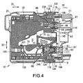
- Fig. 4 is a cross-sectional view of the ink cartridge taken along a IV-IV line in Fig. 1(A) .
- Fig. 5 is a perspective view of a container body, according to an embodiment of the present invention.
- Fig. 6 is a side view of the container body of Fig. 5 .
- Fig. 7 is an exploded, perspective view of container body of Fig. 5 , in which the container body comprises a pair of film walls.
- Fig. 8 is a perspective view of a pivotable member, according to an embodiment of the present invention.
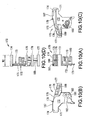
- Fig. 10(A) is a front view of the support block of Fig. 9 .
- Fig. 10(B) is a left side view of the support block of Fig. 9 .
- Fig. 10(C) is a right side view of the support block of Fig. 9 .
- Fig. 10(D) is a plane view of the support block of Fig. 9 .
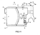
- Fig. 11 is a side view of an ink cartridge assembly comprising an ink cartridge and an opener, according to an embodiment of the present invention.
- Fig. 12 is a side view of the ink cartridge assembly of Fig. 11 , in which a housing and the movable member are omitted.
- Fig. 14(A) is a side view of a seat of the opener of Fig. 11 .
- Fig. 14(B) is a bottom view of the seat of Fig. 14(A) .
- Fig. 14(C) is a front view of the seat of Fig. 14(A) .
- Fig. 14(D) is a cross-sectional view of the seat taken along a line XIVD-XIVD in Fig. 14(C) .
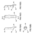
- Fig. 15(B) is a bottom view of the cover of Fig. 15(A) .
- Fig. 15(C) is a front view of the cover of Fig. 15(A) .
- Fig. 15(D) is a cross-sectional view of the cover taken along a line XVD-XVD in Fig. 15(C) .
- Fig. 17 is a partial, cross-sectional view of the ink cartridge assembly of Fig. 11 .
- Fig. 19 is a partial, cross-sectional view of the ink cartridge assembly of Fig. 11 , in which the opener is removed from the ink cartridge.
- Fig. 20 is a side view of an ink cartridge assembly comprising the ink cartridge of Figs. 1(A) and 1(B) and an opener, according to another embodiment of the present invention.
- Fig. 21 is a side view of the ink cartridge assembly of Fig. 20 , in which the housing and the movable member are omitted.
- Fig. 23(A) is a front view of the ink cartridge assembly of Fig. 20 , before a grip portion of the opener is rotated.
- Fig. 23(B) is a side view of the opener and a portion of the ink cartridge of the ink cartridge assembly of Fig. 20 , before a grip portion of the opener is rotated.
- Fig. 23(C) is a cross-sectional view of the opener and the portion of the ink cartridge of Fig. 23(B) .
- Fig. 24(A) is a front view of the ink cartridge assembly of Fig. 20 , in which the grip portion of the opener is rotated to some extent.
- Fig. 24(B) is a side view of the opener and the portion of the ink cartridge of the ink cartridge assembly of Fig. 20 , in which the grip portion of the opener is rotated to some extent.
- Fig. 24(C) is a cross-sectional view of the opener and the portion of the ink cartridge of Fig. 24(B) .
- Fig. 25(A) is a front view of the ink cartridge assembly of Fig. 20 , in which the grip portion of the opener is rotated to the end.
- an ink cartridge 10 is depicted.
- An image recording apparatus e.g., an inkjet printer, uses ink cartridge 10 to form an image on a recording medium (not shown), e.g., paper.
- the ink cartridge 10 is configured to be mounted to and removed from a cartridge storage section (not shown) of the image recording apparatus.
- the ink cartridge 10 is mounted to the cartridge storage section by inserting ink cartridge 10 in a direction indicated by an arrow 30 in Fig. 1 . After the ink cartridge 10 is mounted in the cartridge storage section, ink stored in the ink cartridge 10 is supplied to a recording head (not shown) of the image recording apparatus.
- the housing 26 is configured to protect the container body 20. Substantially the entirety of the container body 20 other than a front face 41 of the container body 20 is covered by the housing 26.
- the housing 26 comprises a first cover member 21 and a second cover member 22 configured to sandwich the container body 20 from the right and left in Fig. 2 . In this embodiment, a pair of films 65 is covered by the first cover member 21 and the second cover member 22.
- the first cover member 21 is attached to a right side face 46 of the container body 20.
- the first cover member 21 comprises a plurality of engaging claws 12 extending from an inner wall surface thereof, and the container body 20 comprises a plurality of engaging grooves 13 formed therein.
- the plurality of engaging claws 12 are fitted into the plurality of engaging grooves 13, respectively, such that the right side face 46 of the container body 20 is covered by the first cover member 21.
- the second cover member 22 is attached to a left side face 45 of the container body 20.
- the second cover member 22 comprises a plurality of engaging claws (not shown) extending from an inner wall surface thereof, and the plurality of engaging claws are fitted in the plurality of engaging grooves 13, respectively, such that the left side face 45 of the container body 20 is covered by the second cover member 22.
- the slider 27 is configured to contact and slide on the front portion 28 of the housing 26 between a first position and a second position in the depth direction, as indicated by the arrow 33, when coil springs 23 and 24 expand and contract.
- the slider 27 is positioned closer to the front face 41 of the container body 20 than when the slider 27 is in the first position, and when the slider 27 is at the first position, as depicted in Fig. 3(B) , the slider 27 is positioned further from the front face 41 of the container body 20 than when the slider 27 is in the second position.
- the slider 27 moves from the first position to the second position.
- an opening 110 formed through the slider 27 is positioned adjacent to the air communication valve mechanism 80, and the ink supply valve mechanism 90 extends outside the slider 27 via an opening 111 formed through the slider 27.
- the predetermined amount of force is released from the slider 27, the slider 27 subsequently moves from the second position to the first position, the opening 110 of the slider 27 moves away from the air communication valve mechanism 80, and the ink supply valve mechanism 90 is positioned within the slider 27.
- the container body 20 has a substantially flat, hexahedron shape having the front face 41, a rear face 42 opposite the front face 41, a top face 43, a bottom face 44 opposite top face 43, the left side face 45, and the right side face 46 opposite the left side face 45.
- Each of the top face 43 and the bottom face 44 is connected to the front face 41 and the rear face 42
- each of the left side face 45 and the right side face 46 is connected to the front face 41, the rear face 42, the top face 43, and the bottom face 44.
- the area of the left side face 45 and the area of the right side face 46 are each greater than each of the area of the front face 41, the area of the rear face 42, the area of the top face 43, and the area of the bottom face 44.
- the frame 50 is formed of a translucent resin material, e.g., a transparent material or a semi-transparent material, and light passes therethrough.
- the frame 50 is manufactured by injection-molding polypropylene.
- the frame 50 may be manufactured by injection-molding polyacetal, nylon, polyethylene, or the like.
- the frame 50 comprises an outer peripheral wall 51 and a plurality of inner walls or inner ribs 52.
- the inner walls or inner ribs 52 are positioned inside the outer peripheral wall 51.
- the outer peripheral wall 51 and the inner walls or inner ribs 52 are integral and define the frame 50.
- the outer peripheral wall 51 and the inner walls or inner ribs 52 extend from the left side face 45 to the right side face 46 of the frame 50.
- the outer peripheral wall 51 has a substantially square or rectangular perimeter extending along the front face 41, the top face 43, the rear face 42, and the bottom surface 44 defining a space in the interior thereof. Accordingly, openings 57 are formed on the left side face 45 and the right side face 46, respectively, of the frame 50, such that the left side face 45 and the right side face 46 of the frame 50 are opened.
- the pair of films 65 e.g., translucent films, is connected to, e.g., adhered to, the side faces 45 and 46, respectively, of the frame 50 via an adhesion method, e.g., a thermal adhesion method. More specifically, the pair of films 65 is adhered to both ends of the outer peripheral wall 51 in the width direction 31.
- the openings 57 are closed by the pair of films 65, and a space surrounded by the outer peripheral wall 51 and the pair of films 65 comprises an ink chamber 100 configured to store ink therein.
- a container-shaped frame which is opened only on the right side face 46 may be used instead of the frame 50. In this case, the ink chamber 100 is defined by the film 65 adhered to the right side face 46 of the container-shaped frame.
- the frame 50 comprises a partitioning plate 53, extending from the outer peripheral wall 51, which partitions an upper space of the ink chamber 100 at the center in the width direction 31.
- the inner walls or inner ribs 52 extend from the outer peripheral wall 51 or the partitioning plate 53.
- the pair of films 65 is also adhered to the inner walls or inner ribs 52 at both ends thereof in the width direction 31. Consequently, the inner walls or inner ribs 52 restrict the ability of the pair of films 65, the first cover member 21, and/or the second cover member 22 to move inward, such that the inner walls or inner ribs 52 limit an amount of deformation of the pair of films 65.
- a lower portion of the ink chamber 100 e.g., a space 102 below the partitioning panel 53, is not partitioned in the width direction 31 and extends from the left side face 45 to the right side face 46, such that the pivotable member 70 and the supporting block 170 are positioned therein.
- the frame 50 comprises a cylindrical ink introduction chamber 105 formed in the rear face 42 of the frame 50 adjacent to the lower end of the rear face 42.
- the ink introduction chamber 105 extends from the rear face 42 towards the ink chamber 100.
- the ink introduction chamber 105 is configured to be in fluid communication with the ink chamber 100. Ink is introduced into the ink chamber 100 through the ink introduction chamber 105 during the manufacturing process of the ink cartridge 10. More specifically, air is removed from the interior of the ink chamber 100 until the pressure in the ink chamber 100 is reduced to a predetermined pressure.
- the translucent portion 140 projects outward from a center portion of front face 41 of the frame 50 away from the ink chamber 100.
- the translucent portion 140 comprises five rectangular walls and have a substantially a hollow box shape.
- the translucent portion 140 comprises a front wall 140A, a pair of side walls 140B, a top wall 140C, and a bottom wall 140D.
- the front wall 140A extends parallel to the front face 41 and is separated from the front face 41 by a predetermined distance.
- the pair of side walls 140B are connected to the front face 41 and the front wall 140A, the top wall 140C is connected to top ends of the front wall 140A and the side walls 140B, and the bottom wall 140D is connected to bottom ends of the front wall 140A and the side walls 140B.
- the width of the front wall 140A is less than the width of the front face 41.
- the translucent portion 140 is configured to receive light emitted from an optical sensor, e.g., a photo interrupter.
- an optical sensor e.g., a photo interrupter.
- a light emitting portion of a photo interrupter faces one of the side walls 140B and a light receiving portion of the photo interrupter faces the other of the side walls 140B.
- the light emitted from the light emitting portion of the photo interrupter may pass through the side walls 140B and reach the light receiving portion of the photo interrupter.
- At least one engaging claw 144 is formed on each of the side walls 140B of the translucent portion 140. Each engaging claw 144 extends outward from one of the side walls 140B in a direction perpendicular to the side walls 140B. Each engaging claw 144 has a hook shape.
- the air communication valve mechanism 80 When the ink cartridge 10 is mounted to the image forming apparatus, the air communication valve mechanism 80 is positioned above the translucent portion 140.
- the air communication valve mechanism 80 is configured to selectively open and close an opening 81 formed through an upper portion of the front face 41 of the frame 50, such that air communication valve mechanism 80 selectively allows and prevents fluid communication between the interior of the ink chamber 100 and the exterior of the ink chamber 100 via the opening 81.
- the air communication valve mechanism 80 comprises a valve member 87, a rod 88 extending from the valve member 87, an urging member, e.g., a spring 86, a stopper 83, and a cap 85.
- valve member 97 is resiliently urged by the spring 96 toward the stopper 93, such that the ink supply valve mechanism 90 is in the closed position unless a force substantially opposite and greater than the biasing force of the spring 96 is applied to the valve member 97.
- the valve member 97 is pushed by a tube of the image recording apparatus against the biasing force of the spring 96, and the opening 91 is opened. Consequently, ink in the ink chamber 100 is allowed to flow from the opening 91 to the image recording apparatus via the tube.
- a supporting member 115 is be positioned on the top face 43 of the frame 50 adjacent to the front face 41 of the frame 50.
- the supporting member 115 is integral with the frame 50.
- the supporting member 115 is configured to support the slider 27, such that the slider 27 slides with respect to the container body 20.
- the supporting member 115 also is configured to restrict the sliding range of the slider 27.
- the slider 27 is slidably supported by the supporting member 115 and a supporting member 116.
- the supporting member 115 comprises a seat 118 extending away from the top face 43 in a direction perpendicular to the top face 43, and a hook-shaped engaging claw 15 which is positioned at and extends from the front end of the seat 118 in a direction perpendicular to the top face 43.
- the supporting member 116 is formed on the bottom face 44 of the frame 50 adjacent to the front face 41 of the frame 50.
- the supporting member 116 has substantially the same shape as the supporting member 115.
- the supporting member 116 is integral with the frame 50, and comprises a seat 124 extending away from the bottom face 44 in a direction perpendicular to the bottom face 44, and a hook-shaped engaging claw 16 which is positioned at and extends from the front end of the seat 124 in a direction perpendicular to the bottom face 44.
- the pivotable member 70 is configured to indicate whether the ink chamber 100 has a sufficient amount of ink stored therein.
- the indicating portion 72 is positioned at a first end of the pivotable member 70, and a float portion 73 is positioned at a second end of the pivotable member 70.
- the pivotable member 70 has the shaft hole 78 formed therethrough.
- the shaft hole 78 is positioned between the first end of the pivotable member and the second end of the pivotable member.
- the shaft 77 is inserted into the shaft hole 78, and the shaft 77 supports the pivotable member 70, such that the pivotable member 70 pivots about the shaft 77 in a direction indicated by an arrow 35 in Fig. 6 .
- the shaft 77 is supported by the cylindrical tube 67 formed on the rib 74 at one end thereof, and by the supporting block 170 at the other end thereof.
- the shaft 77 may be integral with the pivotable member 70.
- the specific gravity of float portion 73 is less than the specific gravity of ink stored in the ink chamber 100.
- the float portion 73 has a hollow formed therein, and floats on ink, such that the float portion 70 moves upward and downward based on the amount of ink within the ink chamber 100, and the pivotable member 70 pivots based on the movement of float portion 73.
- the float portion 73 does not have the hollow, and comprises a material having a specific gravity less than the specific gravity of ink.
- the pivotable member 70 comprises a first portion 75 extending from the shaft hole 78 to the indicating portion 72, and a second portion 76 extending from the shaft hole 78 to the float portion 73.
- the mass of the first portion 75 of the pivotable member 70 is less than the mass of the second portion 76 of the pivotable member 70, such that when the second portion 76 of the pivotable member 70 and the first portion 75 of the pivotable member 70 are in the same medium as each other, the second portion 76 of the pivotable member 70 is heavier than the first portion 75 of the pivotable member 70. Accordingly, when the amount of ink stored in the ink chamber is less than a sufficient amount of ink, the pivotable member 70 pivots counterclockwise about the shaft 77 in Fig.
- the indicating portion 72 separates from the bottom wall 140D of the translucent portion 140.
- the pivotable member 70 stops pivoting and the indicating portion 72 is positioned at the upper position.
- the indicating portion 72 is at the upper position, it is determined that the ink chamber 100 has an insufficient amount of ink stored therein.
- the float portion 73 is submerged in the ink, and a buoyancy force acts on the float portion 73.
- the buoyancy force is great enough to cause the pivotable member 70 to pivot clockwise about the shaft 77 in Fig. 6 .
- the indicating portion 72 contacts the bottom wall 140D of the translucent portion 140, and the pivotable member 70 stops pivoting and the indicating portion 72 is positioned at the lower position.
- the indicating portion 72 is at the lower position, it is determined that the ink chamber 100 has a sufficient amount of ink stored therein.
- Whether or not the ink chamber 100 has a sufficient amount of ink stored therein is determined by a user viewing the position of the indicating portion 72 in the inner space 142, or by using an optical sensor e.g., a photo interrupter, to monitor the position of the indicating portion 72.
- an optical sensor e.g., a photo interrupter
- the protecting member 150 is positioned around the pivotable member 70.
- the protecting member 150 is manufactured by bending a linear steel wire.
- the protecting member 150 comprises a U-shaped portion 150A which is received by a hook 131 formed on the frame 50, and ends 150B of the protecting member 150 are inserted into a hole (not shown) formed through the rib 74 and a hole 183 formed through the supporting block 170, respectively.
- the supporting block 170 is depicted.
- a portion of the outer peripheral wall 51 and a portion of the protecting member 150 are illustrated in broken lines for the convenience of description.
- the supporting block 170 is configured to support the shaft 77 and to support the pair of films 65 which may bend toward the ink chamber 100.
- the supporting block 170 is positioned in a lower portion of the ink chamber 100, e.g., in the space 102.
- the supporting block 170 is configured to be removable from the frame 50.
- the supporting block 170 comprises a plate 171 and a plurality of ribs 174-177.
- the plate 171 and the ribs 174-177 are formed of the same material as the frame 50.
- the rib 174 and the rib 175 extend in a direction perpendicular to a first surface 172 of the plate 171.
- Each of the ribs 174 and 175 is substantially L-shaped, as shown in Fig. 10(B) .
- the rib 174 and the rib 175 are positioned adjacent to an upper end 187 of the plate 171.
- the rib 174 and the rib 175 are separated from each other by a predetermined distance. Consequently, an opening 179 which has a substantially C-shape is formed by the plate 171, the rib 174, and the rib 175.
- a portion of the first portion 75 of the pivotable member 70 is positioned in the opening 179, and the pivotable member 70 is pivotable within the range defined by the opening 179.
- the supporting block 170 also comprises a supporting portion 189 extending from the rib 175 substantially in the depth direction 33.
- the supporting portion 189 extends from substantially a widthwise center of the rib 175 toward the direction away from the rib 174.
- the rib 176 and the rib 177 are positioned on the supporting portion 189.
- the rib 176 and the rib 177 are separated from each other by a predetermined distance. Therefore, the ribs 174-177 are positioned at dispersed places in the space 102.
- Each of the rib 176 and the rib 177 is substantially L-shaped. Each of the ribs 176 and 177 extends in the same direction as the ribs 174 and 175 extend, and has the same width W2 as the ribs 174 and 174. Each of the ribs 176 and 177 extends the same distance from the supporting portion 189 in opposite directions.
- the width W2 of the ribs 174-177 is selected, such that the pair of films 65 do not contact the pivotable member 70 when the pair of films 65 are drawn toward the ink chamber 100. More specifically, the width W2 of the ribs 174 and 175 is greater than a width W1 of the float portion 73, which is the portion of the pivotable member 70 which has the greatest width.
- a groove 182 is formed in a lower portion of the first surface 172 of the plate 172.
- the groove 182 has a substantially triangular shape.
- a hole 183 is formed through the plate 172 at a vertex 181 of the triangular groove 182.
- a cylindrical tube 185 is formed on a second surface 173 of the plate 172, and an end of the shaft 77 is received in the cylindrical tube 185.
- the supporting block 170 is attached to the rib 74 with the second surface 173 facing the rib 74, such that the shaft 77 is inserted into the shaft hole 78 of the pivotable member 70, one end of the shaft 77 is received in the cylindrical tube 185 of the supporting block 170, and the other end of the shaft 77 is received in the cylindrical tube 67 of the rib 74.
- the pivotable member 70 is thereby pivotably supported, and a portion of the first portion 75 of the pivotable member 70 is positioned in the opening 179.
- the ribs 174-177 extend perpendicular to and between the left side face 45 and the right side face 46.
- the slider 27 has a container shape, and is configured to accommodate a front portion of the container body 20 therein.
- the slider 27 has a flat shape corresponding to the outer shape of the front portion of the container body 20.
- the slider comprises a front wall 161 facing and covering the front face 41 of the container body 20, a top wall 163 covering at least a portion of the top face 43 of the container body 20, a bottom wall 164 covering at least a portion of the bottom face 44 of the container body 20, a left wall 165 covering at least a portion of the left side face 45 of the container body 20, and a right wall 166 covering at least a portion of the right side face 46 of the container body 20.
- a portion of the front portion 28 of the housing 26 is positioned between the top wall 163 and the at least a portion of the top face 43, another portion of the front portion 28 is positioned between the bottom wall 164 and the at least a portion of the bottom face 44, still another portion of the front portion 28 is positioned between the left wall 165 and the at least a portion of the left side face 45, and yet another portion of the front portion 28 is positioned between the right wall 166 and the at least a portion of the right side face 46.
- the walls 161, and 163-166 define a space therein, which is configured to accommodate the front portion of the container body 20.
- the coil springs 23 and 24 are compression coil springs, e.g., the coil springs 23 and 24 are compressed and stored in the spring receivers 23A and 24A, respectively, when the front portion of the container body 20 is inserted into the slider 27. Therefore, the coil springs 23 and 24 urge or bias slider 27 in the direction away from the front face 41 of the container body 20 independent of the position of the slider 27.
- the slider 27 When the front portion of the container body 20 is inserted into the slider 27, the slider 27 is urged away from the front face 41 by the coil springs 23 and 24. Therefore, unless an external force is applied to the slider 27, the slider 27 remains in the first position (shown in Fig 3(B) ) corresponding to the slider's 27 furthest distance from front face 41 of the container body 20. The slider 27 remains in the first position by the contact between the projecting strip 120 and the engaging claw 15 and the contact between the projecting strip 126 and the engaging claw 16. Nevertheless, when an external force greater than the biasing force is applied to the front wall 161 of the slider 27, the slider 27 slides from the first position to the second position (shown in Fig. 3(A) ) corresponding to the slider's 27 closest distance to front face 41 of the container body 20.
- the opening 111 is formed through the front wall 161 adjacent to the lower end of the front wall 161.
- the opening 111 is formed at a position corresponding to the ink supply valve mechanism 90.
- the opening 111 has a size which is sufficient to allow the cap 95 of the ink supply valve mechanism 90 to be inserted therein, and when the slider 27 is slid from the first position (see Fig. 3(B) ) to the second position (see Fig. 3(A) ), the cap 95 emerges from the opening 111.
- the seat 206 is configured to be directly attached to the ink cartridge 10.
- the seat 206 is formed of the same resin material as the frame 50, and is manufactured using injection-molding.
- the seat 206 has a hollow shape opening in an attachment direction 224 along which the opener 200 is attached to the ink cartridge 10.
- the attachment direction 224 is parallel to a direction in which the rod 88 extends from the valve member 87 of the air communication valve mechanism 80.
- the seat 206 comprises an attachment portion 214 configured to be attached to and contact the ink cartridge 10.
- the seat 206 also comprises the two arms 218 and 219 extending from the attachment portion 214 in the attachment direction 224.
- the arms 218 and 219 are separated by a particular distance in the height direction of the seat 206.
- the arm 218 is positioned at a position corresponding to the engaging claw 15 of the supporting member 115, and the arm 219 is positioned at a position corresponding to the engaging claws 144 of the translucent portion 140.
- the arm 218 is substantially hook shaped. Supporting portions 226 are positioned between a proximal end 218A and a distal end 218B of the arm 218. Referring to Fig. 14(C) , the supporting portions 226 connect the inner wall surface of the seat 206 and the arm 218. Accordingly, the arm 218 is supported by the supporting portions 226 in the interior of the seat 206. Because the arm 218 is supported in this manner, when no external force is applied to the proximal end 218A of the arm 218, the arm 218 is in an engaging position, as indicated by a solid line in Fig. 18 , in which the arm 218 is engageable with the container body 20.
- the arm 219 is substantially hook shaped.
- the arm 219 is bifurcated from a proximal end 219A to a pair of distal ends 219B, such that the arm 219 is separated into two branches towards the distal ends 219B.
- the positions of the two bifurcated distal ends 219B correspond to the two engaging claws 144 of the translucent portion 140, respectively.
- Supporting portions 228 are positioned between the proximal end 219A and the distal ends 219B of the arm 219. Referring to Fig. 14(C) , the supporting portions 228 connect the inner wall surface of the seat 206 with the arm 219.
- the arm 219 is supported by the supporting portions 228 in the interior of the seat 206. Because the arm 219 is supported in this manner, when no external force is applied to the proximal end 219A of the arm 219, the arm 219 is in an engaging position, as indicated by a solid line in Fig. 18 , in which the arm 219 is engageable with the container body 20. Nevertheless, when an external force is applied to the proximal end 219A of the arm in the attachment direction 224, the arm 219 moves, and the distal ends 219B retract outward, i.e., downward in Fig. 14(D) , such that the arm 219 moves to a releasing position, as indicated by a broken line in Fig. 18 , in which the arm 219 is disengaged from the container body 20.
- the attachment portion 214 comprises a substantially cylindrical guide 204.
- the guide 204 is positioned at a position corresponding to the opening 110 of the slider 27. When the seat 206 is attached to the ink cartridge 10, the guide 204 is inserted into the opening 110.
- the guide 204 has an inner hole (not numbered) formed therethrough, and a rod 244 of the operation member 210 is configured to be inserted into the inner hole of the guide 204.
- a bearing 232 is formed through the seat 206.
- the cover 208 is attached to the seat 206 and is configured to be pivotable about the shaft 212 which is inserted into the bearing 232 and a bearing 236 of the cover 208.
- a storage section 234 is formed in the interior of the seat 206.
- the storage section 234 is configured to store the operation member 210 and to slidably support the operation member 210 therein.
- the storage section 234 is defined by a side wall of the seat 206 having a shape corresponding to the shape of the operation member 210.
- the cover 208 comprises an engaging claw 238.
- the engaging claw 238 engages a catch 225 positioned on the seat 206.
- a lever portion 240 positioned at the end of the cover 208 receives a force, the lever portion 240 moves to disengage the engaging claw 238 from the catch 225.
- the cover 208 comprises a storage section 241 configured to receive, e.g., store, a pressing portion 246 of the operation member 210 therein.
- the storage section 241 is configured to store the pressing portion 246 therein at least when the cover 200 is closed with respect to the seat 206.
- the operation member 210 is configured to be stored in the storage section 234 of the seat 206.
- the operation member 210 has a mushroom shape, and comprises the rod 244 and the pressing portion 246.
- the engaging portion of the engaging claws 248, which engage the elongated holes 229, respectively, has a surface area which is less than the surface area of the elongated holes 229 in the elongated direction of the elongated holes 229, e.g., a width of the engaging portion of the elongating claws 248 is less than a diameter of the elongated holes 229.
- the engaging claws 248 are configured to slide within the elongated holes 229 between one end of the elongated holes 229 and the other end of the elongated holes 229.
- the operation member 210 is configured to move between a projected position in which the pressing portion 246 projects from the seat 206, and a retracted position in which the pressing portion 246 is retracted into the seat 206.
- the operation member 210 is separated from the air communication valve mechanism 80.
- the rod 244 contacts and pushes the valve member 87 of the air communication valve mechanism 80 to open the opening 81.
- the cover 208 is rotated towards the seat 206, such that the claw 238 of the cover 208 engages the catch 225 of the seat 206, which completes the method of assembling.
- a method of attaching the opener 200 to the ink cartridge 10 is described. After ink is introduced into the ink chamber 100 and the pressure in the ink chamber 100 is reduced to be less than the atmospheric pressure, the slider 27 is pressed to the second position, and then the opener 200 is attached to the ink cartridge 10.
- the attachment portion 214 of the opener 200 is aligned to the front wall 161 of the slider 27, and the guide 204 is positioned to face the opening 110.
- the guide 204 is inserted into the opening 110.
- the engaging claw 221 of the arm 218 contacts the engaging claw 15.
- a method of removing the opener 200 from the ink cartridge 10 is described.
- the lever portion 240 of the cover 208 is pressed to release the engagement between the cover 208 and the seat 206. Subsequently, as shown in Fig. 18 , the cover 208 is rotated to expose the pressing portion 246 of the operation member 210.
- the pressing portion 246 is pressed toward the container body 20
- the distal end of the rod 244 applies a force to the rod 88 extending from the valve member 87 to push the rod 88 toward the ink chamber 100.
- valve member 87 then moves from the closed position in which the valve member 87 closes the opening 81 to the open position in which the valve member 87 opens the opening 81 against a biasing force of the spring 86. This allows the ink chamber 100 of the container body 20 to communicate with the atmosphere, such that the pressure in the ink chamber 100 is equalized with the atmospheric pressure.
- the pressing portion 246 contacts the proximal end 218A of the arm 218 and the proximal end 219A of the arm 219, respectively.
- the arm 218 is flexed by a pressing force applied to the proximal end 218A, the distal end 218B is retracted outward, i.e., upward in Fig. 18 , and the arm 218 moves to the releasing position as indicated by the broken line in Fig. 18 , which releases the engagement of the engaging claws 221 and 15.
- the arm 219 is flexed by a pressing force applied to the proximal end 219A, which releases the engagement of the engaging claws 222 and 144.
- the opening 81 is opened at substantially the same time that the engagement between the opener 200 and the ink container 20 is released. Therefore, the opening 81 is opened reliably before mounting the ink cartridge 10 to a recording apparatus. Consequently, when the ink cartridge 10 is mounted to a recording apparatus, backflow of ink from a recording head to the ink chamber 100 is prevented.
- the seat 256 is configured to be directly attached to the ink cartridge 10.
- the seat 256 is configured to be attached to the ink cartridge 10 along an attachment direction 274.
- the attachment direction 274 is parallel to a direction in which the rod 88 extends from the valve member 87 of the air communication valve mechanism 80.
- the operation member 260 is configured to be movable relative to the seat 256 in a direction which is parallel to the attachment direction 274.
- the attachment direction 274 is substantially perpendicular to the front face 41 of the container body 20.
- the seat 256 is formed of the same resin material as the frame 50, and is manufactured using injection-molding.
- the seat 256 has an L-shape, and comprises an attachment portion 264 configured to be attached to a portion of the slider 27 adjacent to the opening 110, and a cover portion 265 configured to cover the translucent portion 140.
- the seat 256 comprises an arm 269 extending from a proximal end 269A, which is positioned adjacent to the attachment portion 264, in a direction substantially perpendicular to the attachment direction 274, and is bent to extend along the attachment direction 274 toward the ink cartridge 10 within the cover portion 265.
- the arm 269 is bifurcated from the proximal end 269A to a pair of distal ends 269B, such that the arm 269 is separated into two branches towards the distal ends 269B.
- the arm 269 is configured to be positioned, such that two bifurcated distal ends 219B engage the two engaging claws 144 of the translucent portion 140, respectively.
- a supporting portion 276 is positioned between the proximal end 269A and the distal ends 269B of the arm 269.
- the supporting portion 276 has a plate shape extending from the arm 269 to an end 276A of the supporting portion 276 in a direction parallel to the attachment direction 274.
- the end 276A of the supporting portion 276 is connected to inner surfaces of the cover portion 265 in the width direction 31, such that the arm 269 is supported by the supporting portion 276 within the cover portion 265.
- the arm 269 When no external force is applied to the proximal end 269A of the arm 269, the arm 269 is in an engaging position, as shown in Figs. 20 , 21 , 23(C) and 24(C) , in which the arm 269 is engageable with the container body 20.
- the arm 269 flexes and rotate around the end 276A of the supporting portion 276, such that the distal ends 269B retract outward, i.e., downward in Fig. 25(C) , to a releasing position in which the arm 269 is disengaged from the container body 20.
- the rod 294 has a cylindrical shape, and the diameter of the rod 294 is less than the diameter of the inner hole of the guide 254, such that the rod 294 is inserted into the inner hole of the guide 254.
- the rod 294 is inserted into the inner hole of the guide 254. Subsequently, the operation member 260 is pushed into the storage section 284, such that the side wall 264A of the attachment portion 264 is resiliently deformed to the outside by the operation member 260. When the operation member 260 is further pushed in the attachment portion 264, the pins 298 moves into the slits 279, respectively, which completes the assembly.
- the operation member 260 is prevented from moving relative to the seat 256 in the attachment direction 274 and a direction opposite to the attachment direction 274 because the pins 298 contact edges of the first slit portions 279A or second slit portions 279B, respectively, when such a movement is attempted.
- each pin 298 moves toward the first end of the inclined slit portion 279C or the second end of the inclined slit portion 279C along the inclined slit portion 279C, such that the operation member 260 rotates in the direction 275, and moves in the attachment direction 274 or the direction opposite to the attachment direction 274.
- the operation member 260 when the opener 250 is attached to the ink cartridge 10, and the pins 298 are positioned within the first slit portions 279A, respectively, the operation member 260 is positioned in an unoperated position, in which the operation member 260 is positioned furthest from the front face 41 of the container body 20, such that the rod 294 is positioned furthest from the rod 88 of the valve member 87, as shown in Figs. 23(A)-23(C) .
- the operation member 260 is positioned in an operated position, in which the operation member is positioned closest to the front face 41 of the container body 20, such that the rod 294 contacts and applies a force to the rod 88 of the valve member 87 to open the opening 81, as shown in Figs. 25(A)-25(C) .
- a method of attaching the opener 250 to the ink cartridge 10 is described. After ink is introduced into the ink chamber 100 and the pressure in the ink chamber 100 is reduced to be less than the atmospheric pressure, a force is applied to the slider 27 to position the slider 27 in the second position, and then the opener 250 is attached to the ink cartridge 10. For example, operation member 260 is moved to be positioned in the unoperated position, and the attachment portion 264 is then aligned to the front wall 161 of the slider 27, such that the guide 254 faces the opening 110.
- the opener 250 moves in the attachment direction 274, which is a direction perpendicular to the front wall 161, the guide 254 is inserted into the opening 110.
- the cover portion 265 covers the translucent portion 140, such that the engaging claws 272 contact the engaging claws 144, respectively.
- the arm 269 is resiliently deformed, and the engaging claws 272 move over the engaging claws 144, such that the engaging claws 272 engage the engaging claws 144, respectively. Accordingly, the opener 250 engages the container body 20 to attach to the ink cartridge 10.
- the air communication valve mechanism 80 is covered and protected by the opener 250. Moreover, the slider 27 is retained at the second position against the biasing force of the coil springs 23 and 24. Because the operation member 260 is positioned in the unoperated position, the rod 294 of the operation member 260 does not contact the rod 88 of the valve member 87.
- a method of removing the opener 250 from the ink cartridge 10 is described.
- the operation member 260 When the operation member 260 is positioned in the unoperated position, as shown in Figs. 23(A)-23(C) , the pins 298 are positioned in the first slit portions 279A, respectively. Therefore, even when an external force is applied to the grip portion 296 in the attachment direction 274, the operation member 260 does not move.
- the grip portion 296 is moved in the direction 273
- the pins 298 move from the first slit portions 279A to the inclined slit portions 279C, respectively.
- the operation member 260 rotates in the direction 273 and move in the attachment direction 274 while the pins 298 are guided by the inclined slit portions 279C, respectively.
- the force causes the arm 269 to flex, and the distal ends 269B of the arm 269 retract outward, i.e., downward in Fig. 25(C) , to the releasing position, as shown in Fig. 25(C) , which releases the engagement of the engaging claws 144 and 272.
- the pins 298 When the arm 269 is in the releasing position, the pins 298 have been positioned within the second slit portions 279B, respectively. Subsequently, when the operation member 296 is pulled in the direction opposite to the attachment direction 274, the pins 298 contacts the edges of the second slit portions 279B, respectively, and therefore the opener 250 is entirely removed from the ink cartridge 10.
- the opening 81 is opened, and then the engagement between the opener 250 and the container body 20 is released. Therefore, the one operation of rotating the grip portion 296 leads to two operations of opening the opening 81, and the releasing the engagement.
- the opening 81 is reliably opened before the ink cartridge 10 is mounted to a recording apparatus. Consequently, when the ink cartridge 10 is mounted to a recording apparatus, backflow of ink from a recording head to the ink chamber 100 is prevented.
- the opener 250 is entirely removed from the ink cartridge 10 by pulling the grip portion 296 of the operation member 260. Therefore, the opener 250 is readily removed from the ink cartridge 10.
- the inclined slits 297C may not be inclined with respect to the attachment direction 274.
- the inclined slits 297C may extend parallel to the attachment direction 274.
- the side wall 264A of the attachment portion 264 may comprise pins 298 instead of having the slits 279 formed therethrough, and the peripheral wall of the grip portion 296 may have slits 279 formed therethrough configured to receive the pins 298, instead of comprising the pins 298.
Landscapes
- Ink Jet (AREA)
- Pens And Brushes (AREA)
Abstract
Description
- The present invention relates generally to an ink cartridge assembly, and more specifically, to an ink cartridge assembly comprising an ink cartridge configured to store ink therein, and a cover member which covers an opening, such that when the cover member is removed, the cover member moves a sealing member away from the opening, which allows fluid communication between an interior and an exterior of the ink cartridge.
- A known ink cartridge is configured to be selectively mounted to and removed from a known recording apparatus, e.g., a known inkjet recording apparatus. The ink cartridge includes an ink chamber configured to store ink, and an ink supply portion configured to supply ink from the interior of the ink chamber to the exterior of the ink chamber. When the ink cartridge is mounted to a cartridge storage section of the recording apparatus, a needle of the cartridge storage section is inserted into the ink supply portion, such that ink is supplied from the ink chamber to the recording apparatus.
- The pressure in the ink chamber is less than the atmospheric pressure before the ink cartridge is mounted to the recording apparatus. Therefore, when the ink cartridge is mounted to the recording apparatus, ink may flow back to the ink chamber from the recording apparatus, and menisci of ink in nozzles of a recording head may be damaged. To prevent the backflow of ink, the ink cartridge has an opening formed therethrough. The opening is closed by a sticker before the ink cartridge is mounted to the recording apparatus. Before a user mounts the ink cartridge to the recording apparatus, the user removes the sticker, which equalizes the pressure inside the ink chamber and the atmospheric pressure via the opening. Nevertheless, if the user fails to remove the sticker before mounting the ink cartridge to the recording apparatus, the pressure inside the ink chamber will be less than the atmospheric pressure when the ink cartridge is mounted to the recording apparatus, and ink may flow back to the ink chamber from the recording apparatus.
- Another known recording apparatus has a mechanism configured to expose an opening formed through the ink cartridge, such that the pressure inside the ink chamber equalizes with the atmospheric pressure via the opening before the needle is inserted into the ink supply portion. Such a known ink cartridge is described in
JP-A-2007-55218 JP-A-6-191046 - Yet another known ink cartridge has a valve mechanism configured to selectively open and close an opening formed through the ink cartridge. This known ink cartridge also has a cover member covering the opening and the valve mechanism. With this cover member, the valve mechanism is prevented from being opened inadvertently. Such a known ink cartridge is described in
US 2006/0203051 A1 , for example. Nevertheless, before a user mounts the ink cartridge to a recording apparatus, the user needs to remove the cover member from the ink cartridge, and also the valve mechanism needs to be opened before a needle of the recording apparatus is inserted into an ink supply portion of the ink cartridge. - Therefore, a need has arisen for ink cartridge assemblies which overcome these and other shortcomings of the related art. A technical advantage of the present invention is that an opening of the ink cartridge readily may be opened when a cover member is removed from the ink cartridge before the ink cartridge is mounted to a recording apparatus.
- According to an embodiment of the present invention, an ink cartridge assembly comprises an ink cartridge comprising a body defining an ink chamber therein, and a sealing member. The body has a particular face, and the particular face has a particular opening formed therethrough. An interior of the ink chamber is configured to be in fluid communication with an exterior of the ink chamber via the particular opening, and the sealing member is configured to close the particular opening. The ink cartridge assembly also comprises a cover member comprising a first portion configured to engage the body, and a second portion. The cover member is configured to attached to the ink cartridge and to cover the particular opening when the first portion engages the body. When the second portion moves, the second portion is configured to apply a particular force to the sealing member to move the sealing member in a predetermined direction away from the particular opening and toward the ink chamber to allow fluid communication between the interior of the ink chamber and the exterior of the ink chamber, and is configured to disengage the first portion from the body.
- With this configuration, the particular opening of the ink cartridge is readily opened when the cover member is removed from the ink cartridge before the ink cartridge is mounted to a recording apparatus.
- The sealing member may comprise an adhesive member, and when the second portion moves the second portion may be configured to puncture at least one portion of the adhesive member and to move the at least one portion of the adhesive member away from the particular opening and toward the ink chamber. Alternatively, the sealing member may comprise a valve mechanism.
- The valve mechanism may comprises, a valve member and an urging member. The urging member may be configured to apply a biasing force to the valve member to urge the valve member toward the particular opening, and when the second portion moves the second portion may be configured to apply the particular force to the valve member to move the valve member away from the particular opening against the biasing force.
- The valve mechanism further may comprise a rod extending from the valve member in the predetermined direction, and when the second portion moves the second portion may be configured to push the rod to apply the particular force to the valve member to move the valve member away from the particular opening.
- The ink cartridge further may comprises a movable member and at least one resilient member. The movable member may be configured to move with respect to the body between a first position and a second position. A distance between the second position and the particular face may be less than a distance between the first position and the particular face. At least one resilient member may be coupled to the particular face and to the movable member. The at least one resilient member may be configured to apply a further force to the movable member to urge the movable member into the first position. When the first portion engages the body the cover member may be configured to position the movable member in the second position against the further force, and when the first portion is disengaged from the body the at least one resilient member may position the movable member in the second position.
- The second portion may be configured to move relative to the first portion in the particular direction between an unoperated position and an operated position, and a distance between the unoperated position and the particular face may be greater than a distance between the operated position and the particular face.
- One of the first portion and the second portion may comprise at least one slit formed therethrough, and the other of the first portion and the second portion may comprise at least one pin configured to be positioned within the at least one slit.
- The at least one slit may comprises a first slit portion and a second slit portion connected to a particular end of the first slit portion, and the second slit may portion extend in a direction which is substantially perpendicular to the particular direction. With this configuration, when the least one pin is positioned within the second slit, an inadvertent movement of the second portion in the particular direction is prevented.
- The at least one pin may be positioned within the second slit portion when the operation member is positioned in the unoperated position, and the at least one pin may be positioned within the first slit portion when the operation member is positioned between the unoperated position and the operated position. With this configuration, when the operation member is positioned in the unoperated position, an inadvertent movement of the second portion in the particular direction is prevented.
- The at least one slit further may comprise a third slit portion connected to a further end of the first slit portion which is opposite from the particular end of the first slit portion. The third slit portion may extend in a direction which is substantially perpendicular to the particular direction, and at least one pin may be positioned within the third slit portion when the operation member is positioned in the operated position. When the operation member is positioned in the operated position, the first portion is disengaged from the body. Therefore, with this configuration, by pulling the second portion away from the ink cartridge, the cover member is entirely removed from the ink cartridge.
- The at least one pin may be positioned within the second slit portion when the operation member is positioned in the operated position, and the at least one pin may be positioned within the first slit portion when the operation member is positioned between the unoperated position and the operated position. When the operation member is positioned in the operated position, the first portion is disengaged from the body. Therefore, with this configuration, by pulling the second portion away from the ink cartridge, the cover member is entirely removed from the ink cartridge.
- The first slit potion may extend in a direction which is inclined with respect to the particular direction. With this configuration, the second portion may rotate relative to the first portion when the second portion moves.
- Other objects, features, and advantages of embodiments of the present invention will be apparent to persons of ordinary skill in the art from the following description of preferred embodiments with reference to the accompanying drawings.
- For a more complete understanding of the present invention, the needs satisfied thereby, and the objects, features, and advantages thereof, reference now is made to the following description taken in connection with the accompanying drawings.
-
Figs. 1(A) and 1(B) are a front-face perspective view and a rear-face perspective view of an ink cartridge, respectively, according to an embodiment of the present invention. -
Fig. 2 is an exploded, perspective view of the ink cartridge ofFigs. 1(A) and 1(B) . -
Figs. 3(A) and 3(B) are side views of the ink cartridge ofFigs. 1(A) and 1(B) , respectively, in which a movable member, such as a slider, is in a second position and a first position, respectively. -
Fig. 4 is a cross-sectional view of the ink cartridge taken along a IV-IV line inFig. 1(A) . -
Fig. 5 is a perspective view of a container body, according to an embodiment of the present invention. -
Fig. 6 is a side view of the container body ofFig. 5 . -
Fig. 7 is an exploded, perspective view of container body ofFig. 5 , in which the container body comprises a pair of film walls. -
Fig. 8 is a perspective view of a pivotable member, according to an embodiment of the present invention. -
Fig. 9 is a perspective view of a supporting block, according to an embodiment of the present invention. -
Fig. 10(A) is a front view of the support block ofFig. 9 . -
Fig. 10(B) is a left side view of the support block ofFig. 9 . -
Fig. 10(C) is a right side view of the support block ofFig. 9 . -
Fig. 10(D) is a plane view of the support block ofFig. 9 . -
Fig. 11 is a side view of an ink cartridge assembly comprising an ink cartridge and an opener, according to an embodiment of the present invention. -
Fig. 12 is a side view of the ink cartridge assembly ofFig. 11 , in which a housing and the movable member are omitted. -
Fig. 13 is an exploded, perspective view of the opener ofFig. 11 . -
Fig. 14(A) is a side view of a seat of the opener ofFig. 11 . -
Fig. 14(B) is a bottom view of the seat ofFig. 14(A) . -
Fig. 14(C) is a front view of the seat ofFig. 14(A) . -
Fig. 14(D) is a cross-sectional view of the seat taken along a line XIVD-XIVD inFig. 14(C) . -
Fig. 15(A) is a side view of a cover of the opener ofFig. 11 . -
Fig. 15(B) is a bottom view of the cover ofFig. 15(A) . -
Fig. 15(C) is a front view of the cover ofFig. 15(A) . -
Fig. 15(D) is a cross-sectional view of the cover taken along a line XVD-XVD inFig. 15(C) . -
Fig. 16(A) is a side view of an operation member of the opener ofFig. 11 . -
Fig. 16(B) is a cross-sectional view of the operation member taken along a line XVIB-XVIB inFig. 16(A) . -
Fig. 17 is a partial, cross-sectional view of the ink cartridge assembly ofFig. 11 . -
Fig. 18 is a partial, cross-sectional view of the ink cartridge assembly ofFig. 11 , in which the operation member is pressed. -
Fig. 19 is a partial, cross-sectional view of the ink cartridge assembly ofFig. 11 , in which the opener is removed from the ink cartridge. -
Fig. 20 is a side view of an ink cartridge assembly comprising the ink cartridge ofFigs. 1(A) and 1(B) and an opener, according to another embodiment of the present invention. -
Fig. 21 is a side view of the ink cartridge assembly ofFig. 20 , in which the housing and the movable member are omitted. -
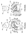
Fig. 22 is an exploded, perspective view of the opener ofFig. 20 . -
Fig. 23(A) is a front view of the ink cartridge assembly ofFig. 20 , before a grip portion of the opener is rotated. -
Fig. 23(B) is a side view of the opener and a portion of the ink cartridge of the ink cartridge assembly ofFig. 20 , before a grip portion of the opener is rotated. -
Fig. 23(C) is a cross-sectional view of the opener and the portion of the ink cartridge ofFig. 23(B) . -
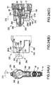
Fig. 24(A) is a front view of the ink cartridge assembly ofFig. 20 , in which the grip portion of the opener is rotated to some extent. -
Fig. 24(B) is a side view of the opener and the portion of the ink cartridge of the ink cartridge assembly ofFig. 20 , in which the grip portion of the opener is rotated to some extent. -
Fig. 24(C) is a cross-sectional view of the opener and the portion of the ink cartridge ofFig. 24(B) . -
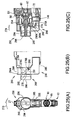
Fig. 25(A) is a front view of the ink cartridge assembly ofFig. 20 , in which the grip portion of the opener is rotated to the end. -
Fig. 25(B) is a side view of the opener and the portion of the ink cartridge assembly ofFig. 20 , in which the grip portion of the opener is rotated to the end. -
Fig. 25(C) is a cross-sectional view of the opener and the portion of the ink cartridge ofFig. 25(B) . - Embodiments of the present invention and their features and technical advantages may be understood by referring to
Figs. 1(A)-19 , like numerals being used for like corresponding portions in the various drawings. - Referring to
Figs. 1(A) and 1(B) , anink cartridge 10, according to an embodiment of the present invention, is depicted. An image recording apparatus (not shown), e.g., an inkjet printer, usesink cartridge 10 to form an image on a recording medium (not shown), e.g., paper. Theink cartridge 10 is configured to be mounted to and removed from a cartridge storage section (not shown) of the image recording apparatus. Theink cartridge 10 is mounted to the cartridge storage section by insertingink cartridge 10 in a direction indicated by anarrow 30 inFig. 1 . After theink cartridge 10 is mounted in the cartridge storage section, ink stored in theink cartridge 10 is supplied to a recording head (not shown) of the image recording apparatus. - The
ink cartridge 10 has a substantially flat, hexahedron shape. A width of theink cartridge 10, as indicated by anarrow 31, is relatively short, and each of a height of theink cartridge 10, as indicated by anarrow 32, and a depth of theink cartridge 10, as indicated by anarrow 33, is greater than the width of theink cartridge 10. - Referring to
Figs. 1(A)-3(B) , theink cartridge 10 comprises acontainer body 20, ahousing 26, a movable member, e.g., aslider 27, and at least one resilient member, e.g., a pair ofcoil springs housing 26 and theslider 27 encloses thecontainer body 20. - The
housing 26 is configured to protect thecontainer body 20. Substantially the entirety of thecontainer body 20 other than afront face 41 of thecontainer body 20 is covered by thehousing 26. Thehousing 26 comprises afirst cover member 21 and asecond cover member 22 configured to sandwich thecontainer body 20 from the right and left inFig. 2 . In this embodiment, a pair offilms 65 is covered by thefirst cover member 21 and thesecond cover member 22. - The
first cover member 21 is attached to aright side face 46 of thecontainer body 20. Thefirst cover member 21 comprises a plurality of engagingclaws 12 extending from an inner wall surface thereof, and thecontainer body 20 comprises a plurality of engaginggrooves 13 formed therein. The plurality of engagingclaws 12 are fitted into the plurality of engaginggrooves 13, respectively, such that theright side face 46 of thecontainer body 20 is covered by thefirst cover member 21. Similarly, thesecond cover member 22 is attached to aleft side face 45 of thecontainer body 20. Thesecond cover member 22 comprises a plurality of engaging claws (not shown) extending from an inner wall surface thereof, and the plurality of engaging claws are fitted in the plurality of engaginggrooves 13, respectively, such that theleft side face 45 of thecontainer body 20 is covered by thesecond cover member 22. - The
container body 20 may comprise a sealing member, e.g., an aircommunication valve mechanism 80, and an inksupply valve mechanism 90 positioned at thefront face 41 thereof. Theslider 27 is configured to protect the aircommunication valve mechanism 80 and the inksupply valve mechanism 90. Theslider 27 may be coupled to thecontainer body 20 by the coil springs 23 and 24 positioned therebetween, and is configured to move relative to thecontainer body 20. An end of thecoil spring 23 is received in aspring receiver 23A formed in an upper portion of thefront face 41 of thecontainer body 20, and an end of thecoil spring 24 is received in aspring receiver 24A formed in a lower portion of thefront face 41 of thecontainer body 20. - The
slider 27 is configured to contact and slide on thefront portion 28 of thehousing 26 between a first position and a second position in the depth direction, as indicated by thearrow 33, when coil springs 23 and 24 expand and contract. When theslider 27 is at the second position, as depicted inFig. 3(A) , theslider 27 is positioned closer to thefront face 41 of thecontainer body 20 than when theslider 27 is in the first position, and when theslider 27 is at the first position, as depicted inFig. 3(B) , theslider 27 is positioned further from thefront face 41 of thecontainer body 20 than when theslider 27 is in the second position. When a predetermined amount of force greater than a biasing force of the coil springs 23 and 24 is applied to theslider 27, theslider 27 moves from the first position to the second position. When theslider 27 is in the second position, anopening 110 formed through theslider 27 is positioned adjacent to the aircommunication valve mechanism 80, and the inksupply valve mechanism 90 extends outside theslider 27 via anopening 111 formed through theslider 27. When the predetermined amount of force is released from theslider 27, theslider 27 subsequently moves from the second position to the first position, theopening 110 of theslider 27 moves away from the aircommunication valve mechanism 80, and the inksupply valve mechanism 90 is positioned within theslider 27. - Referring to
Figs. 4-10 , thecontainer body 20 has a substantially flat, hexahedron shape having thefront face 41, arear face 42 opposite thefront face 41, atop face 43, abottom face 44 oppositetop face 43, theleft side face 45, and theright side face 46 opposite theleft side face 45. Each of thetop face 43 and thebottom face 44 is connected to thefront face 41 and therear face 42, and each of theleft side face 45 and theright side face 46 is connected to thefront face 41, therear face 42, thetop face 43, and thebottom face 44. Moreover, the area of theleft side face 45 and the area of theright side face 46 are each greater than each of the area of thefront face 41, the area of therear face 42, the area of thetop face 43, and the area of thebottom face 44. - The
container body 20 comprises aframe 50, apivotable member 70, a supporting member, e.g., a supportingblock 170, a protectingmember 150, the aircommunication valve mechanism 80, the inksupply valve mechanism 90, and the pair offilms 65. Theframe 50 defines the six faces 41-46 of thecontainer body 20, such that the six faces 41-46 of thecontainer body 20 correspond to six faces of theframe 50. - The
frame 50 is formed of a translucent resin material, e.g., a transparent material or a semi-transparent material, and light passes therethrough. In this embodiment, theframe 50 is manufactured by injection-molding polypropylene. Alternatively, theframe 50 may be manufactured by injection-molding polyacetal, nylon, polyethylene, or the like. - The
frame 50 comprises an outerperipheral wall 51 and a plurality of inner walls orinner ribs 52. The inner walls orinner ribs 52 are positioned inside the outerperipheral wall 51. The outerperipheral wall 51 and the inner walls orinner ribs 52 are integral and define theframe 50. The outerperipheral wall 51 and the inner walls orinner ribs 52 extend from theleft side face 45 to theright side face 46 of theframe 50. The outerperipheral wall 51 has a substantially square or rectangular perimeter extending along thefront face 41, thetop face 43, therear face 42, and thebottom surface 44 defining a space in the interior thereof. Accordingly,openings 57 are formed on theleft side face 45 and theright side face 46, respectively, of theframe 50, such that theleft side face 45 and theright side face 46 of theframe 50 are opened. - The pair of
films 65, e.g., translucent films, is connected to, e.g., adhered to, the side faces 45 and 46, respectively, of theframe 50 via an adhesion method, e.g., a thermal adhesion method. More specifically, the pair offilms 65 is adhered to both ends of the outerperipheral wall 51 in thewidth direction 31. Theopenings 57 are closed by the pair offilms 65, and a space surrounded by the outerperipheral wall 51 and the pair offilms 65 comprises anink chamber 100 configured to store ink therein. Alternatively, a container-shaped frame which is opened only on theright side face 46 may be used instead of theframe 50. In this case, theink chamber 100 is defined by thefilm 65 adhered to theright side face 46 of the container-shaped frame. - The
frame 50 comprises apartitioning plate 53, extending from the outerperipheral wall 51, which partitions an upper space of theink chamber 100 at the center in thewidth direction 31. The inner walls orinner ribs 52 extend from the outerperipheral wall 51 or thepartitioning plate 53. The pair offilms 65 is also adhered to the inner walls orinner ribs 52 at both ends thereof in thewidth direction 31. Consequently, the inner walls orinner ribs 52 restrict the ability of the pair offilms 65, thefirst cover member 21, and/or thesecond cover member 22 to move inward, such that the inner walls orinner ribs 52 limit an amount of deformation of the pair offilms 65. A lower portion of theink chamber 100, e.g., aspace 102 below thepartitioning panel 53, is not partitioned in thewidth direction 31 and extends from theleft side face 45 to theright side face 46, such that thepivotable member 70 and the supportingblock 170 are positioned therein. - In this embodiment, each of the pair of
films 65 comprises a plurality of layered, synthetic resin films. For example, each of the pair offilms 65 comprises three layers. The innermost layer is formed of a polypropylene, which is the same material as theframe 50. The innermost layer of the pair offilms 65 is adhered to theframe 50. The outermost layer is formed of a polyethylene terephthalate, and the layer sandwiched by the innermost layer and the outermost layer is formed of a nylon. In another embodiment, each of the pair offilms 65 may be formed of a metal foil sandwiched by synthetic resins. In yet another embodiment, each of the pair offilms 65 may be formed of a pulp, a metal, or a natural resin. - The
frame 50 comprises arib 74 positioned at a right-side face 46 side of the outerperipheral wall 51, such that therib 74 is positioned adjacent to a corner between thefront face 41 and thebottom face 44. Acylindrical tube 67 extends from therib 74 towards theleft side face 45. Ashaft 77 having a column shape has a first end fitted into thecylindrical tube 67, and a second end which is supported by the supportingblock 170. Theshaft 77 extends through ashaft hole 78 of thepivotable member 70. - The
frame 50 comprises a cylindricalink introduction chamber 105 formed in therear face 42 of theframe 50 adjacent to the lower end of therear face 42. Theink introduction chamber 105 extends from therear face 42 towards theink chamber 100. Theink introduction chamber 105 is configured to be in fluid communication with theink chamber 100. Ink is introduced into theink chamber 100 through theink introduction chamber 105 during the manufacturing process of theink cartridge 10. More specifically, air is removed from the interior of theink chamber 100 until the pressure in theink chamber 100 is reduced to a predetermined pressure. Because of the pressure differential between the interior and the exterior of theink chamber 100, when a needle (not shown) is inserted into theink introduction chamber 105, ink is drawn into theink chamber 100 through the needle via theink introduction chamber 105. As ink is drawn into theink chamber 100, the pressure inside theink chamber 100 increases. Nevertheless, the predetermined pressure is selected, such that after a sufficient amount of ink is introduced into theink chamber 100 e.g., theink chamber 100 is substantially full, the pressure in theink chamber 100 is slightly less than the atmospheric pressure. - The
frame 50 comprises atranslucent portion 140 positioned at thefront face 41 and extending away from theink chamber 100. An amount of ink stored in theink chamber 100 is optically or visually detected via thetranslucent portion 140. Thetranslucent portion 140 is integral withframe 50, and is formed of the same material asframe 50, e.g., thetranslucent portion 140 is formed of a translucent resin material which allows light to pass therethrough. - The
translucent portion 140 projects outward from a center portion offront face 41 of theframe 50 away from theink chamber 100. Thetranslucent portion 140 comprises five rectangular walls and have a substantially a hollow box shape. For example, thetranslucent portion 140 comprises afront wall 140A, a pair ofside walls 140B, atop wall 140C, and abottom wall 140D. Thefront wall 140A extends parallel to thefront face 41 and is separated from thefront face 41 by a predetermined distance. The pair ofside walls 140B are connected to thefront face 41 and thefront wall 140A, thetop wall 140C is connected to top ends of thefront wall 140A and theside walls 140B, and thebottom wall 140D is connected to bottom ends of thefront wall 140A and theside walls 140B. Moreover, the width of thefront wall 140A is less than the width of thefront face 41. Thetranslucent portion 140 is configured to receive light emitted from an optical sensor, e.g., a photo interrupter. Whenink cartridge 10 is mounted to the image forming apparatus, a light emitting portion of a photo interrupter faces one of theside walls 140B and a light receiving portion of the photo interrupter faces the other of theside walls 140B. The light emitted from the light emitting portion of the photo interrupter may pass through theside walls 140B and reach the light receiving portion of the photo interrupter. - The
translucent portion 140 has aninner space 142 formed therein, which is defined by thefront wall 140A, theside walls 140B, thetop wall 140C, and thebottom wall 140D of thetranslucent portion 140. Theinner space 142 is configured to be in fluid communication with the interior of theink chamber 100. An indicatingportion 72 of thepivotable member 70 is configured to move within theinner space 142 between an upper position and a lower position based on an amount of ink in theink chamber 100. - At least one engaging
claw 144 is formed on each of theside walls 140B of thetranslucent portion 140. Each engagingclaw 144 extends outward from one of theside walls 140B in a direction perpendicular to theside walls 140B. Each engagingclaw 144 has a hook shape. - When the
ink cartridge 10 is mounted to the image forming apparatus, the aircommunication valve mechanism 80 is positioned above thetranslucent portion 140. The aircommunication valve mechanism 80 is configured to selectively open and close anopening 81 formed through an upper portion of thefront face 41 of theframe 50, such that aircommunication valve mechanism 80 selectively allows and prevents fluid communication between the interior of theink chamber 100 and the exterior of theink chamber 100 via theopening 81. The aircommunication valve mechanism 80 comprises avalve member 87, arod 88 extending from thevalve member 87, an urging member, e.g., aspring 86, astopper 83, and acap 85. - The
stopper 83 has an opening formed therethrough. Thestopper 83 is partially positioned in theopening 81, but does not close theopening 81 completely because the opening is formed through thestopper 83. Thevalve member 87 is configured to move between an opened position in which thevalve member 87 is separated from thestopper 83, and a closed position in which thevalve member 87 contracts thestopper 83. When thevalve member 87 is positioned in the opened position, the opening of thestopper 83 is not closed by thevalve member 87, such that theopening 81 is opened. When thevalve member 87 is positioned in the closed position, the opening of thestopper 83 is closed by thevalve member 87, such that theopening 81 is closed. Thevalve member 87 is resiliently urged by thespring 86 toward thestopper 83, such that thevalve member 87 is in the closed position unless a force substantially opposite and greater than the biasing force of thespring 86 is applied to thevalve member 87. - When the
ink cartridge 10 is mounted to the image forming apparatus, the inksupply valve mechanism 90 is positioned below thetranslucent portion 140. The inksupply valve mechanism 90 is configured to selectively open and close anopening 91 formed through a lower portion of thefront face 41 of theframe 50, such that the inksupply valve mechanism 90 selectively allows and prevents fluid communication between the interior of theink chamber 100 and the exterior of theink chamber 100 via theopening 91. The inksupply valve mechanism 90 comprises avalve member 97, aspring 96, aspring receiver 94, astopper 93, and acap 95. Thestopper 93 has an opening formed therethrough. Thestopper 93 is partially positioned in theopening 91, but does not close theopening 91 completely because the opening is formed through thestopper 93. Thevalve member 97 is configured to move between an opened position in which thevalve member 97 is separated from thestopper 93, and a closed position in which thevalve member 97 contacts thestopper 93. When thevalve member 97 is positioned in the opened position, the opening of thestopper 93 is not closed by thevalve member 97, such that theopening 91 is opened. When thevalve member 97 is positioned in the closed position, the opening of thestopper 93 is closed by thevalve member 97, such that theopening 91 is closed. Thevalve member 97 is resiliently urged by thespring 96 toward thestopper 93, such that the inksupply valve mechanism 90 is in the closed position unless a force substantially opposite and greater than the biasing force of thespring 96 is applied to thevalve member 97. When theink cartridge 10 is mounted to the image recording apparatus, thevalve member 97 is pushed by a tube of the image recording apparatus against the biasing force of thespring 96, and theopening 91 is opened. Consequently, ink in theink chamber 100 is allowed to flow from theopening 91 to the image recording apparatus via the tube. - A supporting
member 115 is be positioned on thetop face 43 of theframe 50 adjacent to thefront face 41 of theframe 50. The supportingmember 115 is integral with theframe 50. The supportingmember 115 is configured to support theslider 27, such that theslider 27 slides with respect to thecontainer body 20. The supportingmember 115 also is configured to restrict the sliding range of theslider 27. Theslider 27 is slidably supported by the supportingmember 115 and a supportingmember 116. The supportingmember 115 comprises aseat 118 extending away from thetop face 43 in a direction perpendicular to thetop face 43, and a hook-shaped engagingclaw 15 which is positioned at and extends from the front end of theseat 118 in a direction perpendicular to thetop face 43. - The supporting
member 116 is formed on thebottom face 44 of theframe 50 adjacent to thefront face 41 of theframe 50. The supportingmember 116 has substantially the same shape as the supportingmember 115. The supportingmember 116 is integral with theframe 50, and comprises aseat 124 extending away from thebottom face 44 in a direction perpendicular to thebottom face 44, and a hook-shaped engagingclaw 16 which is positioned at and extends from the front end of theseat 124 in a direction perpendicular to thebottom face 44. - Referring to
Figs. 6-8 , thepivotable member 70 is configured to indicate whether theink chamber 100 has a sufficient amount of ink stored therein. The indicatingportion 72 is positioned at a first end of thepivotable member 70, and afloat portion 73 is positioned at a second end of thepivotable member 70. - The
pivotable member 70 has theshaft hole 78 formed therethrough. Theshaft hole 78 is positioned between the first end of the pivotable member and the second end of the pivotable member. Theshaft 77 is inserted into theshaft hole 78, and theshaft 77 supports thepivotable member 70, such that thepivotable member 70 pivots about theshaft 77 in a direction indicated by anarrow 35 inFig. 6 . Theshaft 77 is supported by thecylindrical tube 67 formed on therib 74 at one end thereof, and by the supportingblock 170 at the other end thereof. Alternatively theshaft 77 may be integral with thepivotable member 70. - The specific gravity of
float portion 73 is less than the specific gravity of ink stored in theink chamber 100. Thefloat portion 73 has a hollow formed therein, and floats on ink, such that thefloat portion 70 moves upward and downward based on the amount of ink within theink chamber 100, and thepivotable member 70 pivots based on the movement offloat portion 73. In another embodiment, thefloat portion 73 does not have the hollow, and comprises a material having a specific gravity less than the specific gravity of ink. - When the
pivotable member 70 pivots clockwise inFig. 6 , the indicatingportion 72 contacts thebottom wall 140D of thetranslucent portion 140, such that further movement of thepivotable member 70 is prevented, and the indicatingportion 72 is positioned at the lower position. Similarly, when thepivotable member 70 pivots counterclockwise inFig. 6 , the indicatingportion 72 moves away from thebottom wall 140D of thetranslucent portion 140, and thefloat portion 73 contacts a bottom surface of theink chamber 100. When thefloat portion 73 contacts the bottom surface of theink chamber 100, further movement of thepivotable member 70 is prevented, and the indicatingportion 72 is at the upper position and separated from thebottom wall 140D of thetranslucent portion 140 by a predetermined distance. - The
pivotable member 70 comprises afirst portion 75 extending from theshaft hole 78 to the indicatingportion 72, and asecond portion 76 extending from theshaft hole 78 to thefloat portion 73. The mass of thefirst portion 75 of thepivotable member 70 is less than the mass of thesecond portion 76 of thepivotable member 70, such that when thesecond portion 76 of thepivotable member 70 and thefirst portion 75 of thepivotable member 70 are in the same medium as each other, thesecond portion 76 of thepivotable member 70 is heavier than thefirst portion 75 of thepivotable member 70. Accordingly, when the amount of ink stored in the ink chamber is less than a sufficient amount of ink, thepivotable member 70 pivots counterclockwise about theshaft 77 inFig. 6 , and the indicatingportion 72 separates from thebottom wall 140D of thetranslucent portion 140. When the lower end of thefloat portion 73 contacts the bottom surface of theink chamber 100, thepivotable member 70 stops pivoting and the indicatingportion 72 is positioned at the upper position. When the indicatingportion 72 is at the upper position, it is determined that theink chamber 100 has an insufficient amount of ink stored therein. - In contrast, when a sufficient amount of ink is stored in the
ink chamber 100, thefloat portion 73 is submerged in the ink, and a buoyancy force acts on thefloat portion 73. The buoyancy force is great enough to cause thepivotable member 70 to pivot clockwise about theshaft 77 inFig. 6 . When thepivotable member 70 pivots clockwise, the indicatingportion 72 contacts thebottom wall 140D of thetranslucent portion 140, and thepivotable member 70 stops pivoting and the indicatingportion 72 is positioned at the lower position. When the indicatingportion 72 is at the lower position, it is determined that theink chamber 100 has a sufficient amount of ink stored therein. - Whether or not the
ink chamber 100 has a sufficient amount of ink stored therein is determined by a user viewing the position of the indicatingportion 72 in theinner space 142, or by using an optical sensor e.g., a photo interrupter, to monitor the position of the indicatingportion 72. - Referring to
Figs. 6 and7 , the protectingmember 150 is positioned around thepivotable member 70. The protectingmember 150 is manufactured by bending a linear steel wire. The protectingmember 150 comprises aU-shaped portion 150A which is received by ahook 131 formed on theframe 50, and ends 150B of the protectingmember 150 are inserted into a hole (not shown) formed through therib 74 and ahole 183 formed through the supportingblock 170, respectively. - Referring to
Figs. 7 ,9 , and10 , the supportingblock 170 is depicted. InFig. 9 , a portion of the outerperipheral wall 51 and a portion of the protectingmember 150 are illustrated in broken lines for the convenience of description. The supportingblock 170 is configured to support theshaft 77 and to support the pair offilms 65 which may bend toward theink chamber 100. The supportingblock 170 is positioned in a lower portion of theink chamber 100, e.g., in thespace 102. The supportingblock 170 is configured to be removable from theframe 50. - The supporting
block 170 comprises aplate 171 and a plurality of ribs 174-177. Theplate 171 and the ribs 174-177 are formed of the same material as theframe 50. - The
rib 174 and therib 175 extend in a direction perpendicular to afirst surface 172 of theplate 171. Each of theribs Fig. 10(B) . Therib 174 and therib 175 are positioned adjacent to anupper end 187 of theplate 171. Therib 174 and therib 175 are separated from each other by a predetermined distance. Consequently, anopening 179 which has a substantially C-shape is formed by theplate 171, therib 174, and therib 175. A portion of thefirst portion 75 of thepivotable member 70 is positioned in theopening 179, and thepivotable member 70 is pivotable within the range defined by theopening 179. - The supporting
block 170 also comprises a supportingportion 189 extending from therib 175 substantially in thedepth direction 33. The supportingportion 189 extends from substantially a widthwise center of therib 175 toward the direction away from therib 174. Therib 176 and therib 177 are positioned on the supportingportion 189. Therib 176 and therib 177 are separated from each other by a predetermined distance. Therefore, the ribs 174-177 are positioned at dispersed places in thespace 102. - Each of the
rib 176 and therib 177 is substantially L-shaped. Each of theribs ribs ribs ribs portion 189 in opposite directions. - The width W2 of the ribs 174-177 is selected, such that the pair of
films 65 do not contact thepivotable member 70 when the pair offilms 65 are drawn toward theink chamber 100. More specifically, the width W2 of theribs float portion 73, which is the portion of thepivotable member 70 which has the greatest width. - A
groove 182 is formed in a lower portion of thefirst surface 172 of theplate 172. Thegroove 182 has a substantially triangular shape. Ahole 183 is formed through theplate 172 at avertex 181 of thetriangular groove 182. When oneend 150B of the protectingmember 150 is pushed along thegroove 182 toward thevertex 181 with the supportingblock 170 disposed in thespace 102, theend 150B is guided to thevertex 181, and then is inserted into thehole 183. Theend 150B of the protectingmember 150 is thereby readily inserted into thehole 183. - A
cylindrical tube 185 is formed on asecond surface 173 of theplate 172, and an end of theshaft 77 is received in thecylindrical tube 185. The supportingblock 170 is attached to therib 74 with thesecond surface 173 facing therib 74, such that theshaft 77 is inserted into theshaft hole 78 of thepivotable member 70, one end of theshaft 77 is received in thecylindrical tube 185 of the supportingblock 170, and the other end of theshaft 77 is received in thecylindrical tube 67 of therib 74. Thepivotable member 70 is thereby pivotably supported, and a portion of thefirst portion 75 of thepivotable member 70 is positioned in theopening 179. Moreover, the ribs 174-177 extend perpendicular to and between theleft side face 45 and theright side face 46. - Because the supporting
block 170 is positioned in thespace 102 of theink chamber 100, even though the pair offilms 65 are drawn towards theink chamber 100 due to the pressure differential between the interior and exterior of theink chamber 100 when ink is introduced into theink chamber 100, the inner surfaces of the pair offilms 65 contact ribs 174-177 of the supportingblock 170. Therefore, deformation of the pair offilms 65 is suppressed, which maintains the capacity of theink chamber 100 at a maximum capacity. Moreover, when an external force is applied to thehousing 26, which causes thehousing 26 to deform toward thecontainer body 20, the deformation of thehousing 26 is suppressed by the ribs 174-177. - Referring to
Figs. 1-4 , theslider 27 is depicted. Theslider 27 has a container shape, and is configured to accommodate a front portion of thecontainer body 20 therein. Theslider 27 has a flat shape corresponding to the outer shape of the front portion of thecontainer body 20. The slider comprises afront wall 161 facing and covering thefront face 41 of thecontainer body 20, atop wall 163 covering at least a portion of thetop face 43 of thecontainer body 20, abottom wall 164 covering at least a portion of thebottom face 44 of thecontainer body 20, aleft wall 165 covering at least a portion of theleft side face 45 of thecontainer body 20, and aright wall 166 covering at least a portion of theright side face 46 of thecontainer body 20. A portion of thefront portion 28 of thehousing 26 is positioned between thetop wall 163 and the at least a portion of thetop face 43, another portion of thefront portion 28 is positioned between thebottom wall 164 and the at least a portion of thebottom face 44, still another portion of thefront portion 28 is positioned between theleft wall 165 and the at least a portion of theleft side face 45, and yet another portion of thefront portion 28 is positioned between theright wall 166 and the at least a portion of theright side face 46. Thewalls 161, and 163-166 define a space therein, which is configured to accommodate the front portion of thecontainer body 20. - The
slider 27 comprises supportingbars slide grooves openings bar 168 is configured to support thecoil spring 23, and the supportingbar 169 is configured to support thecoil spring 24. The supportingbars front wall 161 facing thefront face 41 of thecontainer body 20. The supportingbar 168 is at a position corresponding to thespring receiver 23A, and the supportingbar 169 is at a position corresponding to thespring receiver 24A. - The supporting
bars front wall 161 in thedepth direction 33 of thecontainer body 20. When the front portion of thecontainer body 20 is inserted into theslider 27 when thecoil spring 23 is stored in thespring receiver 23A and thecoil spring 24 is stored in thespring receiver 24A, the supportingbar 168 is inserted into thecoil spring 23 and the supportingbar 169 is inserted into thecoil spring 24. Accordingly, the coil springs 23 and 24 are supported by the supportingbars container body 20. - The coil springs 23 and 24 are compression coil springs, e.g., the coil springs 23 and 24 are compressed and stored in the
spring receivers container body 20 is inserted into theslider 27. Therefore, the coil springs 23 and 24 urge orbias slider 27 in the direction away from thefront face 41 of thecontainer body 20 independent of the position of theslider 27. - The
slide groove 17 is formed in thetop wall 163, and a cross-sectional shape of theslide groove 17 has a substantially inverted U-shape. The supportingmember 115 is inserted into theslide groove 17, and a projectingstrip 120 extends from a bottom surface of thetop wall 163 toward an interior of theslide groove 17. Therefore, theslide groove 17 is narrowed by the projectingstrip 120. Theslide groove 18 is formed in thebottom wall 164, and a cross-sectional shape of theslide groove 18 is substantially a U-shape. The supportingmember 116 is inserted into theslide groove 18, and a projectingstrip 126 extends from a top surface of thebottom wall 164 toward an interior of theslide groove 18. Therefore, theslide groove 18 is narrowed by the projectingstrip 126. - During insertion of the front portion of the
container body 20 into theslider 27, the supportingmember 115 is inserted into theslide groove 17, and the supportingmember 116 is inserted into theslide groove 18. When the supportingmember 115 is inserted into theslide groove 17, the projectingstrip 120 and the engagingclaw 15 contact each other. Then, when the supportingmember 115 is further inserted, the supportingmember 115 bends downward, and the engagingclaw 15 moves to be positioned over the projectingstrip 120. When the engagingclaw 15 has moved over the projectingstrip 120, theslider 27 and thecontainer body 20 are not be disassembled because the engagingclaw 15 is received by the projectingstrip 120. The supportingmember 116 is also inserted into theslide groove 18 in the same manner. - When the front portion of the
container body 20 is inserted into theslider 27, theslider 27 is urged away from thefront face 41 by the coil springs 23 and 24. Therefore, unless an external force is applied to theslider 27, theslider 27 remains in the first position (shown inFig 3(B) ) corresponding to the slider's 27 furthest distance fromfront face 41 of thecontainer body 20. Theslider 27 remains in the first position by the contact between the projectingstrip 120 and the engagingclaw 15 and the contact between the projectingstrip 126 and the engagingclaw 16. Nevertheless, when an external force greater than the biasing force is applied to thefront wall 161 of theslider 27, theslider 27 slides from the first position to the second position (shown inFig. 3(A) ) corresponding to the slider's 27 closest distance tofront face 41 of thecontainer body 20. - The
opening 110 is formed through thefront wall 161 adjacent to the upper end of thefront wall 161. Theopening 110 is formed at a position corresponding to the aircommunication valve mechanism 80. Theopening 110 allows aguide 204 and arod 244 of an opener 200 (seeFig. 11 ) to be inserted therethrough, and has a substantially circular shape. - The
opening 111 is formed through thefront wall 161 adjacent to the lower end of thefront wall 161. Theopening 111 is formed at a position corresponding to the inksupply valve mechanism 90. Theopening 111 has a size which is sufficient to allow thecap 95 of the inksupply valve mechanism 90 to be inserted therein, and when theslider 27 is slid from the first position (seeFig. 3(B) ) to the second position (seeFig. 3(A) ), thecap 95 emerges from theopening 111. - Referring to
Figs. 11-19 , an ink cartridge assembly according to an embodiment of the present invention is depicted. The ink cartridge assembly comprises theink cartridge 10 and anopener 200. Theopener 200 is configured to cover the aircommunication valve mechanism 80 and the inksupply valve mechanism 90 when theopener 200 is attached to theink cartridge 10, and is also configured to cause the aircommunication valve mechanism 80 to open theopening 81. Theopener 200 comprises aseat 206, acover 208, anoperation member 210, and ashaft 212. - The
seat 206 is configured to be directly attached to theink cartridge 10. Theseat 206 is formed of the same resin material as theframe 50, and is manufactured using injection-molding. Theseat 206 has a hollow shape opening in anattachment direction 224 along which theopener 200 is attached to theink cartridge 10. Theattachment direction 224 is parallel to a direction in which therod 88 extends from thevalve member 87 of the aircommunication valve mechanism 80. Theseat 206 comprises anattachment portion 214 configured to be attached to and contact theink cartridge 10. Theseat 206 also comprises the twoarms attachment portion 214 in theattachment direction 224. Thearms seat 206. Thearm 218 is positioned at a position corresponding to the engagingclaw 15 of the supportingmember 115, and thearm 219 is positioned at a position corresponding to the engagingclaws 144 of thetranslucent portion 140. - Referring to
Fig. 14(D) , thearm 218 is substantially hook shaped. Supportingportions 226 are positioned between aproximal end 218A and adistal end 218B of thearm 218. Referring toFig. 14(C) , the supportingportions 226 connect the inner wall surface of theseat 206 and thearm 218. Accordingly, thearm 218 is supported by the supportingportions 226 in the interior of theseat 206. Because thearm 218 is supported in this manner, when no external force is applied to theproximal end 218A of thearm 218, thearm 218 is in an engaging position, as indicated by a solid line inFig. 18 , in which thearm 218 is engageable with thecontainer body 20. Nevertheless, when an external force is applied to theproximal end 218A of thearm 218 in theattachment direction 224, thearm 218 moves, and thedistal end 218B is retracted outward i.e., upward inFig. 14(D) , such that thearm 218 moves to a releasing position, as indicated by a broken line inFig. 18 , in which thearm 218 is disengaged from thecontainer body 20. - Referring to
Fig. 14(D) , thearm 219 is substantially hook shaped. Thearm 219 is bifurcated from aproximal end 219A to a pair of distal ends 219B, such that thearm 219 is separated into two branches towards the distal ends 219B. The positions of the two bifurcated distal ends 219B correspond to the twoengaging claws 144 of thetranslucent portion 140, respectively. Supportingportions 228 are positioned between theproximal end 219A and the distal ends 219B of thearm 219. Referring toFig. 14(C) , the supportingportions 228 connect the inner wall surface of theseat 206 with thearm 219. Accordingly, thearm 219 is supported by the supportingportions 228 in the interior of theseat 206. Because thearm 219 is supported in this manner, when no external force is applied to theproximal end 219A of thearm 219, thearm 219 is in an engaging position, as indicated by a solid line inFig. 18 , in which thearm 219 is engageable with thecontainer body 20. Nevertheless, when an external force is applied to theproximal end 219A of the arm in theattachment direction 224, thearm 219 moves, and the distal ends 219B retract outward, i.e., downward inFig. 14(D) , such that thearm 219 moves to a releasing position, as indicated by a broken line inFig. 18 , in which thearm 219 is disengaged from thecontainer body 20. - A hook-shaped
engaging claw 221 is formed on thedistal end 218B of thearm 218, and the engagingclaw 221 is configured to engage the engagingclaw 15 of the supportingmember 115. Hook-shapedengaging claws 222 are formed on the distal ends 219B of thearm 219, respectively, and the engagingclaws 222 are configured to engage the engagingclaws 144 of thetranslucent portion 140, respectively. Referring toFigs. 11 and12 , theseat 206 is attached to thecontainer body 20 by the engagement between the engagingclaw 221 and the engagingclaw 15 and the engagement between the engagingclaws 222 and the engagingclaws 144, respectively. - The
attachment portion 214 comprises a substantiallycylindrical guide 204. Theguide 204 is positioned at a position corresponding to theopening 110 of theslider 27. When theseat 206 is attached to theink cartridge 10, theguide 204 is inserted into theopening 110. Theguide 204 has an inner hole (not numbered) formed therethrough, and arod 244 of theoperation member 210 is configured to be inserted into the inner hole of theguide 204. - A
bearing 232 is formed through theseat 206. Thecover 208 is attached to theseat 206 and is configured to be pivotable about theshaft 212 which is inserted into thebearing 232 and abearing 236 of thecover 208. - Referring to
Fig. 14(C) , astorage section 234 is formed in the interior of theseat 206. Thestorage section 234 is configured to store theoperation member 210 and to slidably support theoperation member 210 therein. Thestorage section 234 is defined by a side wall of theseat 206 having a shape corresponding to the shape of theoperation member 210. - Referring to
Figs. 13 and15 , thecover 208 comprises an engagingclaw 238. When thecover 208 is moved to be positioned onto theseat 206, the engagingclaw 238 engages acatch 225 positioned on theseat 206. When alever portion 240 positioned at the end of thecover 208 receives a force, thelever portion 240 moves to disengage the engagingclaw 238 from thecatch 225. - The
cover 208 comprises astorage section 241 configured to receive, e.g., store, apressing portion 246 of theoperation member 210 therein. Thestorage section 241 is configured to store thepressing portion 246 therein at least when thecover 200 is closed with respect to theseat 206. - Referring to
Figs. 13 and16 , theoperation member 210 is configured to be stored in thestorage section 234 of theseat 206. Theoperation member 210 has a mushroom shape, and comprises therod 244 and thepressing portion 246. - The
rod 244 has a cylindrical shape. The diameter of therod 244 is less than the diameter of the inner hole of theguide 204, and therefore, therod 244 is inserted into the inner hole of theguide 204. Thepressing portion 246 is connected to an end of therod 244. Thepressing portion 246 comprises twoengaging claws 248. - Referring to
Fig. 13 , a method of assembling theopener 200 is described. In this exemplary method, the bearing 232 of theseat 206 and the bearing 236 of thecover 208 are aligned, and then theshaft 212 is inserted into thebearings operation member 210 is stored in thestorage section 234. When theoperation member 210 is stored in thestorage section 234, therod 244 is inserted into the inner hole of theguide 204. Then, the engagingclaws 248 are fitted into elongatedholes 229 formed through the side wall of theseat 206. - The engaging portion of the engaging
claws 248, which engage theelongated holes 229, respectively, has a surface area which is less than the surface area of theelongated holes 229 in the elongated direction of theelongated holes 229, e.g., a width of the engaging portion of the elongatingclaws 248 is less than a diameter of theelongated holes 229. The engagingclaws 248 are configured to slide within theelongated holes 229 between one end of theelongated holes 229 and the other end of theelongated holes 229. More specifically, theoperation member 210 is configured to move between a projected position in which thepressing portion 246 projects from theseat 206, and a retracted position in which thepressing portion 246 is retracted into theseat 206. When theopener 200 is attached to theink cartridge 10, and theoperation member 210 is in the projected position, theoperation member 210 is separated from the aircommunication valve mechanism 80. Nevertheless, when theoperation member 210 moves from the projected position to the retracted position, therod 244 contacts and pushes thevalve member 87 of the aircommunication valve mechanism 80 to open theopening 81. After theoperation member 210 is stored in thestorage section 234, thecover 208 is rotated towards theseat 206, such that theclaw 238 of thecover 208 engages thecatch 225 of theseat 206, which completes the method of assembling. - Referring to
Fig. 17 , a method of attaching theopener 200 to theink cartridge 10 is described. After ink is introduced into theink chamber 100 and the pressure in theink chamber 100 is reduced to be less than the atmospheric pressure, theslider 27 is pressed to the second position, and then theopener 200 is attached to theink cartridge 10. For example, theattachment portion 214 of theopener 200 is aligned to thefront wall 161 of theslider 27, and theguide 204 is positioned to face theopening 110. Then, when theopener 200 moves in a direction perpendicular to thefront wall 161, theguide 204 is inserted into theopening 110. Subsequently, when theopener 200 is further pressed, the engagingclaw 221 of thearm 218 contacts the engagingclaw 15. When this occurs, thearm 218 is resiliently deformed, and the engagingclaw 221 moves over the engagingclaw 15 and engage the engagingclaw 15. Similarly, the engagingclaws 222 of thearm 219 contacts the engagingclaws 144, thearm 219 is resiliently deformed, and the engagingclaws 222 move over the engagingclaws 144, such that the engagingclaw 222 engage the engagingclaws 144. Accordingly, theopener 200 engages thecontainer body 20 to attach to theink cartridge 10. - The air
communication valve mechanism 80 is covered by theopener 200 and is protected by theopener 200 with theopener 200 attached to theink cartridge 10. Moreover, theslider 27 is retained at the second position against the biasing force of the coils springs 23 and 24. - Referring to
Figs. 17-19 , a method of removing theopener 200 from theink cartridge 10 is described. Thelever portion 240 of thecover 208 is pressed to release the engagement between thecover 208 and theseat 206. Subsequently, as shown inFig. 18 , thecover 208 is rotated to expose thepressing portion 246 of theoperation member 210. When thepressing portion 246 is pressed toward thecontainer body 20, the distal end of therod 244 applies a force to therod 88 extending from thevalve member 87 to push therod 88 toward theink chamber 100. Thevalve member 87 then moves from the closed position in which thevalve member 87 closes theopening 81 to the open position in which thevalve member 87 opens theopening 81 against a biasing force of thespring 86. This allows theink chamber 100 of thecontainer body 20 to communicate with the atmosphere, such that the pressure in theink chamber 100 is equalized with the atmospheric pressure. - When a further force is applied to the
pressing portion 246, thepressing portion 246 contacts theproximal end 218A of thearm 218 and theproximal end 219A of thearm 219, respectively. When this occurs, thearm 218 is flexed by a pressing force applied to theproximal end 218A, thedistal end 218B is retracted outward, i.e., upward inFig. 18 , and thearm 218 moves to the releasing position as indicated by the broken line inFig. 18 , which releases the engagement of the engagingclaws arm 219 is flexed by a pressing force applied to theproximal end 219A, which releases the engagement of the engagingclaws opener 200 is removed from theink cartridge 10 by pulling theopener 200. As such, when engagingclaws claws opener 200 covers theopening 81 and the aircommunication valve mechanism 80, and when a force is applied to theoperation member 210 to move theoperation member 210 toward thecontainer body 20, theoperation member 210 applies a particular force to thevalve member 87 to move thevalve member 87 away from theopening 81 toward theink chamber 100, and theoperation member 210 also disengages engagingclaws claws - In this manner, by operating the
pressing portion 246 of theoperation member 210, theopening 81 is opened at substantially the same time that the engagement between theopener 200 and theink container 20 is released. Therefore, theopening 81 is opened reliably before mounting theink cartridge 10 to a recording apparatus. Consequently, when theink cartridge 10 is mounted to a recording apparatus, backflow of ink from a recording head to theink chamber 100 is prevented. - In another embodiment of the present invention, the air
communication valve mechanism 80 may be replaced by an adhesive member, e.g., a vinyl adhesive tape or film, which is attached to thecontainer body 20 to cover and close theopening 81. The pressure in the ink chamber is equalized with the atmospheric pressure by therod 244 puncturing at least one portion of the adhesive member and pushing the at least one portion of the adhesive member away from theopening 81 and toward theink chamber 100. - Referring to
Figs. 20-25(C) , an ink cartridge assembly according to another embodiment of the present invention is depicted. The ink cartridge assembly of this embodiment comprises theink cartridge 10, and anopener 250 which is removably attached to theink cartridge 10. Theopener 250 is configured to cover the aircommunication valve mechanism 80 and thetranslucent portion 140 when theopener 250 is attached to theink cartridge 10, and also is configured to cause the aircommunication valve mechanism 80 to open theopening 81. Theopener 250 comprises aseat 256 and anoperation member 260. - The
seat 256 is configured to be directly attached to theink cartridge 10. Theseat 256 is configured to be attached to theink cartridge 10 along anattachment direction 274. Theattachment direction 274 is parallel to a direction in which therod 88 extends from thevalve member 87 of the aircommunication valve mechanism 80. Theoperation member 260 is configured to be movable relative to theseat 256 in a direction which is parallel to theattachment direction 274. Theattachment direction 274 is substantially perpendicular to thefront face 41 of thecontainer body 20. Theseat 256 is formed of the same resin material as theframe 50, and is manufactured using injection-molding. Theseat 256 has an L-shape, and comprises anattachment portion 264 configured to be attached to a portion of theslider 27 adjacent to theopening 110, and acover portion 265 configured to cover thetranslucent portion 140. - The
seat 256 comprises anarm 269 extending from aproximal end 269A, which is positioned adjacent to theattachment portion 264, in a direction substantially perpendicular to theattachment direction 274, and is bent to extend along theattachment direction 274 toward theink cartridge 10 within thecover portion 265. Thearm 269 is bifurcated from theproximal end 269A to a pair of distal ends 269B, such that thearm 269 is separated into two branches towards the distal ends 269B. Thearm 269 is configured to be positioned, such that two bifurcated distal ends 219B engage the twoengaging claws 144 of thetranslucent portion 140, respectively. - Hook-shaped
engaging claws 272 are formed on the distal ends 269B of thearm 269, respectively, and the engagingclaws 272 are configured to engage the engagingclaws 144 of thetranslucent portion 140, respectively. Theseat 256 is attached to thecontainer body 20 by the engagement between the engagingclaws 272 and the engagingclaws 144, respectively. - A supporting
portion 276 is positioned between theproximal end 269A and the distal ends 269B of thearm 269. The supportingportion 276 has a plate shape extending from thearm 269 to anend 276A of the supportingportion 276 in a direction parallel to theattachment direction 274. Theend 276A of the supportingportion 276 is connected to inner surfaces of thecover portion 265 in thewidth direction 31, such that thearm 269 is supported by the supportingportion 276 within thecover portion 265. - When no external force is applied to the
proximal end 269A of thearm 269, thearm 269 is in an engaging position, as shown inFigs. 20 ,21 ,23(C) and24(C) , in which thearm 269 is engageable with thecontainer body 20. When an external force is applied to theproximal end 269A of thearm 269 in theattachment direction 274, thearm 269 flexes and rotate around theend 276A of the supportingportion 276, such that the distal ends 269B retract outward, i.e., downward inFig. 25(C) , to a releasing position in which thearm 269 is disengaged from thecontainer body 20. - The
attachment portion 264 comprises a substantiallycylindrical guide 254. Theguide 254 is positioned at a position corresponding to theopening 110 of theslider 27. When theseat 256 is attached to theink cartridge 10, theguide 254 is inserted into theopening 110. Theguide 254 has a cylindrical inner hole (not numbered) formed therethrough, and arod 294 of theoperation member 260 is configured to be inserted into the inner hole of theguide 264. - A
storage section 284 is formed in the interior of theattachment portion 264. Thestorage section 284 is configured to store theoperation member 260 and to slidably support theoperation member 260 therein. Thestorage section 284 is defined by an inner surface of aside wall 264A of theattachment portion 264, and thestorage section 284 has a shape corresponding to the shape of theoperation member 260. - The
side wall 264A of theattachment portion 264 has at least one slit, e.g., twoslits 279, formed therethrough, and theoperation member 260 comprises at lest one pin, e.g., twopins 298, configured to be positioned within the twoslits 279, respectively. Eachslit 279 comprises anfirst slit portion 279A, asecond slit portion 279B, and aninclined slit portion 279C connected to thefirst slit portion 279A at a first end of theinclined slit portion 279C and connected to thesecond slit portion 279B at a second end of theinclined slit portion 279C opposite the first end of theinclined slit portion 279C. Thefirst slit portion 279A extends from the first end of theinclined slit portion 279C in a direction substantially perpendicular to theattachment direction 274, and thesecond slit portion 279B extends from the second end of theinclined slit portion 279C in a direction substantially perpendicular to theattachment direction 274. Theinclined slit portion 279C extends from the first end of theinclined slit portion 279C to the second end of theinclined slit portion 279C in a direction which is inclined with respect to theattachment direction 274. - The
operation member 260 is configured to be stored in thestorage section 284 of theattachment portion 264. Theoperation member 260 has substantially a cylindrical shape, and comprises agrip portion 296 and arod 294 extending from thegrip portion 296. The cylindrical inner hole of theguide 254 has a central axis extending in a direction parallel to theattachment direction 274. Theoperation member 260 is configured to rotate in the interior of thestorage section 284 in adirection 275 about the central axis of theguide 254. Theoperation member 260 also is configured to move in the interior of thestorage section 284 in theattachment direction 274 when theoperation member 260 rotates. - The
rod 294 has a cylindrical shape, and the diameter of therod 294 is less than the diameter of the inner hole of theguide 254, such that therod 294 is inserted into the inner hole of theguide 254. - The
grip portion 296 comprises a peripheral wall comprising the twopins 298. The twopins 298 extend from the peripheral wall of thegrip portion 296 in the normal direction of the peripheral wall of thegrip portion 296, i.e. in a direction perpendicular to the tangent to the peripheral wall of thegrip portion 296. When theoperation member 260 is stored in thestorage section 284, the twopins 298 are positioned within the twoslits 279, respectively. When a user rotates thegrip portion 296, theoperation member 260 rotates in thedirection 275 and moves in theattachment direction 274 while thepins 298 are guided by theslits 279, respectively. - When the
opener 250 is assembled, therod 294 is inserted into the inner hole of theguide 254. Subsequently, theoperation member 260 is pushed into thestorage section 284, such that theside wall 264A of theattachment portion 264 is resiliently deformed to the outside by theoperation member 260. When theoperation member 260 is further pushed in theattachment portion 264, thepins 298 moves into theslits 279, respectively, which completes the assembly. - When the
pins 298 are positioned within thefirst slit portions 279A or thesecond slit portions 279B, respectively, theoperation member 260 is prevented from moving relative to theseat 256 in theattachment direction 274 and a direction opposite to theattachment direction 274 because thepins 298 contact edges of thefirst slit portions 279A orsecond slit portions 279B, respectively, when such a movement is attempted. - When the
grip portion 296 is rotated, thepins 298 move from thefirst slit portions 279A or thesecond slit portions 279B to theinclined slit portions 279C, respectively. When an external force is applied in at least one of theattachment direction 274, a direction opposite to theattachment direction 274, and thedirection 275, to theoperation member 260 whosepins 298 are positioned within theinclined slit portions 279C, eachpin 298 moves toward the first end of theinclined slit portion 279C or the second end of theinclined slit portion 279C along theinclined slit portion 279C, such that theoperation member 260 rotates in thedirection 275, and moves in theattachment direction 274 or the direction opposite to theattachment direction 274. In this embodiment, when thegrip portion 296 is rotated in theclockwise direction 273 inFigs. 23(A) ,24(A) , and25(A) , theoperation member 260 rotates in theclockwise direction 273 and moves in theattachment direction 274. In contrast, when thegrip portion 296 is rotated in the counterclockwise direction, theoperation member 260 rotates in the counterclockwise direction and moves in a direction opposite to theattachment direction 274. - In this embodiment, when the
opener 250 is attached to theink cartridge 10, and thepins 298 are positioned within thefirst slit portions 279A, respectively, theoperation member 260 is positioned in an unoperated position, in which theoperation member 260 is positioned furthest from thefront face 41 of thecontainer body 20, such that therod 294 is positioned furthest from therod 88 of thevalve member 87, as shown inFigs. 23(A)-23(C) . In contrast, when thepins 298 are positioned within thesecond slit portions 279B, respectively, theoperation member 260 is positioned in an operated position, in which the operation member is positioned closest to thefront face 41 of thecontainer body 20, such that therod 294 contacts and applies a force to therod 88 of thevalve member 87 to open theopening 81, as shown inFigs. 25(A)-25(C) . - Referring to
Figs. 23(A)-23(C) , a method of attaching theopener 250 to theink cartridge 10 is described. After ink is introduced into theink chamber 100 and the pressure in theink chamber 100 is reduced to be less than the atmospheric pressure, a force is applied to theslider 27 to position theslider 27 in the second position, and then theopener 250 is attached to theink cartridge 10. For example,operation member 260 is moved to be positioned in the unoperated position, and theattachment portion 264 is then aligned to thefront wall 161 of theslider 27, such that theguide 254 faces theopening 110. Subsequently, when theopener 250 moves in theattachment direction 274, which is a direction perpendicular to thefront wall 161, theguide 254 is inserted into theopening 110. When theopener 250 moves further, thecover portion 265 covers thetranslucent portion 140, such that the engagingclaws 272 contact the engagingclaws 144, respectively. When this occurs, thearm 269 is resiliently deformed, and the engagingclaws 272 move over the engagingclaws 144, such that the engagingclaws 272 engage the engagingclaws 144, respectively. Accordingly, theopener 250 engages thecontainer body 20 to attach to theink cartridge 10. - When the
opener 250 is attached to theink cartridge 10, the aircommunication valve mechanism 80 is covered and protected by theopener 250. Moreover, theslider 27 is retained at the second position against the biasing force of the coil springs 23 and 24. Because theoperation member 260 is positioned in the unoperated position, therod 294 of theoperation member 260 does not contact therod 88 of thevalve member 87. - Referring to
Figs. 23(A)-25(C) , a method of removing theopener 250 from theink cartridge 10 is described. When theoperation member 260 is positioned in the unoperated position, as shown inFigs. 23(A)-23(C) , thepins 298 are positioned in thefirst slit portions 279A, respectively. Therefore, even when an external force is applied to thegrip portion 296 in theattachment direction 274, theoperation member 260 does not move. When thegrip portion 296 is moved in thedirection 273, thepins 298 move from thefirst slit portions 279A to theinclined slit portions 279C, respectively. Theoperation member 260 rotates in thedirection 273 and move in theattachment direction 274 while thepins 298 are guided by theinclined slit portions 279C, respectively. - When the
operation member 260 moves in theattachment direction 274, the distal end of therod 294 of theoperation member 260 contacts the distal end of therod 88 of thevalve member 87, as shown inFigs. 24(A)-24(C) . When theoperation member 260 moves further in theattachment direction 274, therod 294 applies a force to therod 88 to push therod 88 toward theink chamber 100. Thevalve member 87 then moves from the closed position in which thevalve member 87 closes theopening 81 to the open position in which thevalve member 87 opens theopening 81 against a biasing force of thespring 86, as shown inFigs. 25(A)-25(C) . This allows theink chamber 100 of thecontainer body 20 to communicate with the atmosphere, such that the pressure in theink chamber 100 is equalized with the atmospheric pressure. - When the
operation member 260 moves further in theattachment direction 274, anend 296A of thegrip portion 296 positioned adjacent to theproximal end 269A of thearm 269 contacts and applies a force to theproximal end 269A in theattachment direction 274. When this occurs, the force causes thearm 269 to flex, and the distal ends 269B of thearm 269 retract outward, i.e., downward inFig. 25(C) , to the releasing position, as shown inFig. 25(C) , which releases the engagement of the engagingclaws - When the
arm 269 is in the releasing position, thepins 298 have been positioned within thesecond slit portions 279B, respectively. Subsequently, when theoperation member 296 is pulled in the direction opposite to theattachment direction 274, thepins 298 contacts the edges of thesecond slit portions 279B, respectively, and therefore theopener 250 is entirely removed from theink cartridge 10. - As such, when engaging
claws 272 engage engagingclaws 144, respectively, theopener 250 covers theopening 81 and the aircommunication valve mechanism 80, and when theoperation member 260 moves toward thecontainer body 20, theoperation member 260 applies a force to thevalve member 87 to move thevalve member 87 away from theopening 81 toward theink chamber 100, and theoperation member 260 also disengages engagingclaws 272 from the engagingclaws 144, respectively. - In this manner, by rotating the
grip portion 296 of theoperation member 260, theopening 81 is opened, and then the engagement between theopener 250 and thecontainer body 20 is released. Therefore, the one operation of rotating thegrip portion 296 leads to two operations of opening theopening 81, and the releasing the engagement. Theopening 81 is reliably opened before theink cartridge 10 is mounted to a recording apparatus. Consequently, when theink cartridge 10 is mounted to a recording apparatus, backflow of ink from a recording head to theink chamber 100 is prevented. - When the
opener 250 is attached to theink cartridge 10, and thepins 298 are positioned in thefirst slit portions 279A, respectively, even if an external force is applied to thegrip portion 296 of theoperation member 260 in theattachment direction 274, theoperation member 260 does not move. Therefore, theoperation member 260 is prevented from moving inadvertently. - When the
pins 298 are positioned in thesecond slit portions 279B, respectively, theopener 250 is entirely removed from theink cartridge 10 by pulling thegrip portion 296 of theoperation member 260. Therefore, theopener 250 is readily removed from theink cartridge 10. - In another embodiment, the
first slit portions 279A may be omitted, or thesecond slit portions 279B may be omitted. - In another embodiment, the inclined slits 297C may not be inclined with respect to the
attachment direction 274. The inclined slits 297C may extend parallel to theattachment direction 274. - In another embodiment, the
side wall 264A of theattachment portion 264 may comprisepins 298 instead of having theslits 279 formed therethrough, and the peripheral wall of thegrip portion 296 may haveslits 279 formed therethrough configured to receive thepins 298, instead of comprising thepins 298. - While the invention has been described in connection with exemplary embodiments, it will be understood by those skilled in the art that other variations and modifications of the exemplary embodiments described above may be made without departing from the scope of the invention. Other embodiments will be apparent to those skilled in the art from a consideration of the specification or practice of the invention disclosed herein. It is intended that the specification and the described examples are considered merely as exemplary of the invention, with the true scope of the invention being indicated by the flowing claims.
Claims (13)
- An ink cartridge assembly comprising:an ink cartridge (10) comprising:a body (20) defining an ink chamber (100) therein, wherein the body (20) has a particular face (41), and the particular face (41) has a particular opening (81) formed therethrough, wherein an interior of the ink chamber (100) is configured to be in fluid communication with an exterior of the ink chamber (100) via the particular opening (81); anda sealing member (80) configured to close the particular opening; and a cover member (200; 250) comprising:a first portion (206; 256) configured to engage the body (20), wherein the cover member (200; 250) is configured to be attached to the ink cartridge (10) and to cover the particular opening (81) when the first portion (206; 256) engages the body (20); anda second portion (210; 260), wherein, when the second portion (210; 260) moves, the second portion (210; 260) is configured to apply a particular force to the sealing member (80) to move the sealing member (80) in a predetermined direction away from the particular opening (81) and toward the ink chamber (100) to allow fluid communication between the interior of the ink chamber and the exterior of the ink chamber, and to disengage the first portion (206; 256) from the body (20).
- The ink cartridge assembly of claim 1, wherein the sealing member comprises an adhesive member, and when the second portion moves the second portion (210; 260) is configured to puncture at least one portion of the adhesive member and to move the at least one portion of the adhesive member away from the particular opening and toward the ink chamber.
- The ink cartridge assembly of claim 1, wherein the sealing member comprises a valve mechanism (80).
- The ink cartridge assembly of claim 3, wherein the valve mechanism (80) comprises:a valve member (87); andan urging member (86), wherein the urging member (86) is configured to apply a biasing force to the valve member (87) to urge the valve member toward the particular opening (81), and, when the second portion (210; 260) moves, the second portion (210; 260) is configured to apply the particular force to the valve member (87) to move the valve member away from the particular opening (81) against the biasing force.
- The ink cartridge assembly of claim 4, wherein the valve mechanism (80) further comprises a rod (88) extending from the valve member (87) in the predetermined direction, and, when the second portion (210; 260) moves, the second portion (210; 260) is configured to push the rod (88) to apply the particular force to the valve member (87) to move the valve member away from the particular opening (81).
- The ink cartridge assembly of any one of claims 1-5, wherein the ink cartridge (10) further comprises:a movable member (27) configured to move with respect to the body (20) between a first position and a second position, wherein a distance between the second position and the particular face (41) is less than a distance between the first position and the particular face; andat least one resilient member (23, 24) coupled to the particular face (41) and to the movable member (27), wherein the at least one resilient member (23, 24) is configured to apply a further force to the movable member (27) to urge the movable member into the first position, wherein, when the first portion (206; 256) engages the body (20), the cover member (200; 250) is configured to position the movable member (27) in the second position against the further force, and, when the first portion (206; 256) is disengaged from the body (20), the at least one resilient member (23, 24) positions the movable member (27) in the second position.
- The ink cartridge assembly of any one of clams 1-6, wherein the second portion (210; 260) is configured to move relative to the first portion (206; 256) in the particular direction between an unoperated position and an operated position, wherein a distance between the unoperated position and the particular face (41) is greater than a distance between the operated position and the particular face (41).
- The ink cartridge assembly of claim 7, wherein one of the first portion (256) and the second portion (260) comprises at least one slit (279) formed therethrough, and the other of the first portion (256) and the second portion (260) comprises at least one pin (298) configured to be positioned within the at least one slit (279).
- The ink cartridge assembly of claim 8, wherein the at least one slit (279) comprises a first slit portion (279C) and a second slit portion (279A; 279B) connected to a particular end of the first slit portion (279C), and the second slit portion (279A; 279B) extends in a direction which is substantially perpendicular to the particular direction.
- The ink cartridge assembly of claim 9, wherein the at least one pin (298) is positioned within the second slit portion (279A) when the second portion (260) is positioned in the unoperated position, and the at least one pin (298) is positioned within the first slit portion (279C) when the second portion (260) is positioned between the unoperated position and the operated position.
- The ink cartridge assembly of claim 10, wherein the at least one slit (279) further comprises a third slit portion (279B) connected to a further end of the first slit portion (279C) which is opposite from the particular end of the first slit portion (279C), wherein the third slit portion (279B) extends in a direction which is substantially perpendicular to the particular direction, wherein at least one pin (298) is positioned within the third slit portion (279B) when the second portion (260) is positioned in the operated position.
- The ink cartridge assembly of claim 9, wherein the at least one pin (298) is positioned within the second slit portion (279A; 279B) when the second portion (260) is positioned in the operated position; and the at least one pin (298) is positioned within the first slit portion (279C) when the second portion (260) is positioned between the unoperated position and the operated position.
- The ink cartridge assembly of any one of claims 9-12, wherein the first slit portion (279C) extends in a direction which is inclined with respect to the particular direction.
Priority Applications (3)
| Application Number | Priority Date | Filing Date | Title |
|---|---|---|---|
| EP08003714A EP2039522B1 (en) | 2008-02-28 | 2008-02-28 | Ink cartridge assembly |
| DE602008000867T DE602008000867D1 (en) | 2008-02-28 | 2008-02-28 | ink assembly |
| AT08003714T ATE461821T1 (en) | 2008-02-28 | 2008-02-28 | INK CARTRIDGE ASSEMBLY |
Applications Claiming Priority (1)
| Application Number | Priority Date | Filing Date | Title |
|---|---|---|---|
| EP08003714A EP2039522B1 (en) | 2008-02-28 | 2008-02-28 | Ink cartridge assembly |
Publications (2)
| Publication Number | Publication Date |
|---|---|
| EP2039522A1 true EP2039522A1 (en) | 2009-03-25 |
| EP2039522B1 EP2039522B1 (en) | 2010-03-24 |
Family
ID=39456508
Family Applications (1)
| Application Number | Title | Priority Date | Filing Date |
|---|---|---|---|
| EP08003714A Not-in-force EP2039522B1 (en) | 2008-02-28 | 2008-02-28 | Ink cartridge assembly |
Country Status (3)
| Country | Link |
|---|---|
| EP (1) | EP2039522B1 (en) |
| AT (1) | ATE461821T1 (en) |
| DE (1) | DE602008000867D1 (en) |
Citations (12)
| Publication number | Priority date | Publication date | Assignee | Title |
|---|---|---|---|---|
| EP0439728A2 (en) * | 1989-12-06 | 1991-08-07 | Canon Kabushiki Kaisha | Package for ink jet cartridge |
| EP0559206A2 (en) * | 1992-03-06 | 1993-09-08 | Canon Kabushiki Kaisha | Containers for containing expendables, its packaging material and method for collecting the same |
| JPH06191046A (en) | 1992-12-25 | 1994-07-12 | Seiko Epson Corp | Inkjet recording device |
| EP0861732A2 (en) * | 1997-02-14 | 1998-09-02 | Canon Kabushiki Kaisha | Ink-jet cartridge and method of storing print head |
| US6097407A (en) * | 1988-11-09 | 2000-08-01 | Canon Kabushiki Kaisha | Package for ink jet head |
| US6113230A (en) * | 1995-09-29 | 2000-09-05 | Canon Kabushiki Kaisha | Ink tank package container having a seal member |
| US20010038407A1 (en) * | 1998-10-15 | 2001-11-08 | Seiko Epson Corporation | Ink cartridge device |
| US6623104B1 (en) * | 1999-10-04 | 2003-09-23 | Canon Kabushiki Kaisha | Liquid container, cap used with the liquid container, and cap-equipped liquid container |
| US20060203051A1 (en) | 2005-03-10 | 2006-09-14 | Brother Kogyo Kabushiki Kaisha | Ink cartridge |
| JP2007055218A (en) | 2005-07-25 | 2007-03-08 | Hitachi Maxell Ltd | Ink cartridge mounting mechanism |
| US20070064080A1 (en) * | 2005-09-22 | 2007-03-22 | Brother Kogyo Kabushiki Kaisha | Storage housing for storing recording head |
| US20070222835A1 (en) * | 2006-03-27 | 2007-09-27 | Pui-Kuong Lui | Ink cartridge |
-
2008
- 2008-02-28 EP EP08003714A patent/EP2039522B1/en not_active Not-in-force
- 2008-02-28 DE DE602008000867T patent/DE602008000867D1/en active Active
- 2008-02-28 AT AT08003714T patent/ATE461821T1/en not_active IP Right Cessation
Patent Citations (12)
| Publication number | Priority date | Publication date | Assignee | Title |
|---|---|---|---|---|
| US6097407A (en) * | 1988-11-09 | 2000-08-01 | Canon Kabushiki Kaisha | Package for ink jet head |
| EP0439728A2 (en) * | 1989-12-06 | 1991-08-07 | Canon Kabushiki Kaisha | Package for ink jet cartridge |
| EP0559206A2 (en) * | 1992-03-06 | 1993-09-08 | Canon Kabushiki Kaisha | Containers for containing expendables, its packaging material and method for collecting the same |
| JPH06191046A (en) | 1992-12-25 | 1994-07-12 | Seiko Epson Corp | Inkjet recording device |
| US6113230A (en) * | 1995-09-29 | 2000-09-05 | Canon Kabushiki Kaisha | Ink tank package container having a seal member |
| EP0861732A2 (en) * | 1997-02-14 | 1998-09-02 | Canon Kabushiki Kaisha | Ink-jet cartridge and method of storing print head |
| US20010038407A1 (en) * | 1998-10-15 | 2001-11-08 | Seiko Epson Corporation | Ink cartridge device |
| US6623104B1 (en) * | 1999-10-04 | 2003-09-23 | Canon Kabushiki Kaisha | Liquid container, cap used with the liquid container, and cap-equipped liquid container |
| US20060203051A1 (en) | 2005-03-10 | 2006-09-14 | Brother Kogyo Kabushiki Kaisha | Ink cartridge |
| JP2007055218A (en) | 2005-07-25 | 2007-03-08 | Hitachi Maxell Ltd | Ink cartridge mounting mechanism |
| US20070064080A1 (en) * | 2005-09-22 | 2007-03-22 | Brother Kogyo Kabushiki Kaisha | Storage housing for storing recording head |
| US20070222835A1 (en) * | 2006-03-27 | 2007-09-27 | Pui-Kuong Lui | Ink cartridge |
Also Published As
| Publication number | Publication date |
|---|---|
| ATE461821T1 (en) | 2010-04-15 |
| EP2039522B1 (en) | 2010-03-24 |
| DE602008000867D1 (en) | 2010-05-06 |
Similar Documents
| Publication | Publication Date | Title |
|---|---|---|
| US7018030B2 (en) | Ink cartridge and ink-jet recording apparatus | |
| US7237882B2 (en) | Ink cartridge having retaining structure and recording apparatus for receiving the ink cartridge | |
| US8292417B2 (en) | Ink cartridges and methods of manufacturing such ink cartridges | |
| US8052260B2 (en) | Ink cartridges and ink supply systems | |
| US20090141105A1 (en) | Ink cartridges and ink supply systems | |
| JP7520574B2 (en) | LIQUID CARTRIDGE AND LIQUID EJECTION DEVICE | |
| JP2001105617A (en) | Liquid storage container, cap used for the liquid storage container, and liquid storage container with cap | |
| JP4888357B2 (en) | Ink supply device | |
| US8087765B2 (en) | Ink supply systems | |
| CN101376295B (en) | Ink cartridge assemblies | |
| JP2009132118A (en) | Ink supply device | |
| US7819512B2 (en) | Packaging arrangements | |
| CN101376290B (en) | Packaging device | |
| US8024860B2 (en) | Methods for manufacturing an ink cartridge | |
| US8038278B2 (en) | Ink cartridges | |
| EP2095955B1 (en) | Packaging arrangement | |
| US8152287B2 (en) | Ink cartridge assemblies | |
| EP2039522B1 (en) | Ink cartridge assembly | |
| US7815299B2 (en) | Ink cartridges | |
| US7942513B2 (en) | Ink cartridges | |
| EP2095959B1 (en) | Ink cartridges and methods of manufacturing the same | |
| US8079685B2 (en) | Ink cartridges and methods of manufacturing the same | |
| EP2095957A1 (en) | Ink cartridge | |
| EP2095956B1 (en) | Method for manufacturing an ink cartridge | |
| JP4946204B2 (en) | Ink cartridge and printer |
Legal Events
| Date | Code | Title | Description |
|---|---|---|---|
| PUAI | Public reference made under article 153(3) epc to a published international application that has entered the european phase |
Free format text: ORIGINAL CODE: 0009012 |
|
| AK | Designated contracting states |
Kind code of ref document: A1 Designated state(s): AT BE BG CH CY CZ DE DK EE ES FI FR GB GR HR HU IE IS IT LI LT LU LV MC MT NL NO PL PT RO SE SI SK TR |
|
| AX | Request for extension of the european patent |
Extension state: AL BA MK RS |
|
| 17P | Request for examination filed |
Effective date: 20090402 |
|
| 17Q | First examination report despatched |
Effective date: 20090630 |
|
| GRAP | Despatch of communication of intention to grant a patent |
Free format text: ORIGINAL CODE: EPIDOSNIGR1 |
|
| AKX | Designation fees paid |
Designated state(s): AT BE BG CH CY CZ DE DK EE ES FI FR GB GR HR HU IE IS IT LI LT LU LV MC MT NL NO PL PT RO SE SI SK TR |
|
| GRAS | Grant fee paid |
Free format text: ORIGINAL CODE: EPIDOSNIGR3 |
|
| GRAA | (expected) grant |
Free format text: ORIGINAL CODE: 0009210 |
|
| AK | Designated contracting states |
Kind code of ref document: B1 Designated state(s): AT BE BG CH CY CZ DE DK EE ES FI FR GB GR HR HU IE IS IT LI LT LU LV MC MT NL NO PL PT RO SE SI SK TR |
|
| REG | Reference to a national code |
Ref country code: GB Ref legal event code: FG4D |
|
| REG | Reference to a national code |
Ref country code: CH Ref legal event code: EP |
|
| REG | Reference to a national code |
Ref country code: IE Ref legal event code: FG4D |
|
| REF | Corresponds to: |
Ref document number: 602008000867 Country of ref document: DE Date of ref document: 20100506 Kind code of ref document: P |
|
| REG | Reference to a national code |
Ref country code: NL Ref legal event code: T3 |
|
| PG25 | Lapsed in a contracting state [announced via postgrant information from national office to epo] |
Ref country code: LT Free format text: LAPSE BECAUSE OF FAILURE TO SUBMIT A TRANSLATION OF THE DESCRIPTION OR TO PAY THE FEE WITHIN THE PRESCRIBED TIME-LIMIT Effective date: 20100324 Ref country code: NO Free format text: LAPSE BECAUSE OF FAILURE TO SUBMIT A TRANSLATION OF THE DESCRIPTION OR TO PAY THE FEE WITHIN THE PRESCRIBED TIME-LIMIT Effective date: 20100624 Ref country code: HR Free format text: LAPSE BECAUSE OF FAILURE TO SUBMIT A TRANSLATION OF THE DESCRIPTION OR TO PAY THE FEE WITHIN THE PRESCRIBED TIME-LIMIT Effective date: 20100324 |
|
| LTIE | Lt: invalidation of european patent or patent extension |
Effective date: 20100324 |
|
| PG25 | Lapsed in a contracting state [announced via postgrant information from national office to epo] |
Ref country code: PL Free format text: LAPSE BECAUSE OF FAILURE TO SUBMIT A TRANSLATION OF THE DESCRIPTION OR TO PAY THE FEE WITHIN THE PRESCRIBED TIME-LIMIT Effective date: 20100324 Ref country code: AT Free format text: LAPSE BECAUSE OF FAILURE TO SUBMIT A TRANSLATION OF THE DESCRIPTION OR TO PAY THE FEE WITHIN THE PRESCRIBED TIME-LIMIT Effective date: 20100324 Ref country code: FI Free format text: LAPSE BECAUSE OF FAILURE TO SUBMIT A TRANSLATION OF THE DESCRIPTION OR TO PAY THE FEE WITHIN THE PRESCRIBED TIME-LIMIT Effective date: 20100324 Ref country code: LV Free format text: LAPSE BECAUSE OF FAILURE TO SUBMIT A TRANSLATION OF THE DESCRIPTION OR TO PAY THE FEE WITHIN THE PRESCRIBED TIME-LIMIT Effective date: 20100324 Ref country code: SI Free format text: LAPSE BECAUSE OF FAILURE TO SUBMIT A TRANSLATION OF THE DESCRIPTION OR TO PAY THE FEE WITHIN THE PRESCRIBED TIME-LIMIT Effective date: 20100324 |
|
| PG25 | Lapsed in a contracting state [announced via postgrant information from national office to epo] |
Ref country code: BE Free format text: LAPSE BECAUSE OF FAILURE TO SUBMIT A TRANSLATION OF THE DESCRIPTION OR TO PAY THE FEE WITHIN THE PRESCRIBED TIME-LIMIT Effective date: 20100324 Ref country code: GR Free format text: LAPSE BECAUSE OF FAILURE TO SUBMIT A TRANSLATION OF THE DESCRIPTION OR TO PAY THE FEE WITHIN THE PRESCRIBED TIME-LIMIT Effective date: 20100625 Ref country code: EE Free format text: LAPSE BECAUSE OF FAILURE TO SUBMIT A TRANSLATION OF THE DESCRIPTION OR TO PAY THE FEE WITHIN THE PRESCRIBED TIME-LIMIT Effective date: 20100324 Ref country code: ES Free format text: LAPSE BECAUSE OF FAILURE TO SUBMIT A TRANSLATION OF THE DESCRIPTION OR TO PAY THE FEE WITHIN THE PRESCRIBED TIME-LIMIT Effective date: 20100705 Ref country code: RO Free format text: LAPSE BECAUSE OF FAILURE TO SUBMIT A TRANSLATION OF THE DESCRIPTION OR TO PAY THE FEE WITHIN THE PRESCRIBED TIME-LIMIT Effective date: 20100324 Ref country code: SE Free format text: LAPSE BECAUSE OF FAILURE TO SUBMIT A TRANSLATION OF THE DESCRIPTION OR TO PAY THE FEE WITHIN THE PRESCRIBED TIME-LIMIT Effective date: 20100324 |
|
| PG25 | Lapsed in a contracting state [announced via postgrant information from national office to epo] |
Ref country code: IS Free format text: LAPSE BECAUSE OF FAILURE TO SUBMIT A TRANSLATION OF THE DESCRIPTION OR TO PAY THE FEE WITHIN THE PRESCRIBED TIME-LIMIT Effective date: 20100724 Ref country code: SK Free format text: LAPSE BECAUSE OF FAILURE TO SUBMIT A TRANSLATION OF THE DESCRIPTION OR TO PAY THE FEE WITHIN THE PRESCRIBED TIME-LIMIT Effective date: 20100324 Ref country code: BG Free format text: LAPSE BECAUSE OF FAILURE TO SUBMIT A TRANSLATION OF THE DESCRIPTION OR TO PAY THE FEE WITHIN THE PRESCRIBED TIME-LIMIT Effective date: 20100624 Ref country code: CZ Free format text: LAPSE BECAUSE OF FAILURE TO SUBMIT A TRANSLATION OF THE DESCRIPTION OR TO PAY THE FEE WITHIN THE PRESCRIBED TIME-LIMIT Effective date: 20100324 |
|
| PLBE | No opposition filed within time limit |
Free format text: ORIGINAL CODE: 0009261 |
|
| STAA | Information on the status of an ep patent application or granted ep patent |
Free format text: STATUS: NO OPPOSITION FILED WITHIN TIME LIMIT |
|
| PG25 | Lapsed in a contracting state [announced via postgrant information from national office to epo] |
Ref country code: DK Free format text: LAPSE BECAUSE OF FAILURE TO SUBMIT A TRANSLATION OF THE DESCRIPTION OR TO PAY THE FEE WITHIN THE PRESCRIBED TIME-LIMIT Effective date: 20100324 |
|
| 26N | No opposition filed |
Effective date: 20101228 |
|
| PG25 | Lapsed in a contracting state [announced via postgrant information from national office to epo] |
Ref country code: IT Free format text: LAPSE BECAUSE OF FAILURE TO SUBMIT A TRANSLATION OF THE DESCRIPTION OR TO PAY THE FEE WITHIN THE PRESCRIBED TIME-LIMIT Effective date: 20100324 |
|
| PG25 | Lapsed in a contracting state [announced via postgrant information from national office to epo] |
Ref country code: MC Free format text: LAPSE BECAUSE OF NON-PAYMENT OF DUE FEES Effective date: 20110228 |
|
| REG | Reference to a national code |
Ref country code: IE Ref legal event code: MM4A |
|
| PG25 | Lapsed in a contracting state [announced via postgrant information from national office to epo] |
Ref country code: MT Free format text: LAPSE BECAUSE OF FAILURE TO SUBMIT A TRANSLATION OF THE DESCRIPTION OR TO PAY THE FEE WITHIN THE PRESCRIBED TIME-LIMIT Effective date: 20100324 |
|
| PG25 | Lapsed in a contracting state [announced via postgrant information from national office to epo] |
Ref country code: IE Free format text: LAPSE BECAUSE OF NON-PAYMENT OF DUE FEES Effective date: 20110228 |
|
| REG | Reference to a national code |
Ref country code: CH Ref legal event code: PL |
|
| PG25 | Lapsed in a contracting state [announced via postgrant information from national office to epo] |
Ref country code: CH Free format text: LAPSE BECAUSE OF NON-PAYMENT OF DUE FEES Effective date: 20120229 Ref country code: LI Free format text: LAPSE BECAUSE OF NON-PAYMENT OF DUE FEES Effective date: 20120229 |
|
| PG25 | Lapsed in a contracting state [announced via postgrant information from national office to epo] |
Ref country code: CY Free format text: LAPSE BECAUSE OF FAILURE TO SUBMIT A TRANSLATION OF THE DESCRIPTION OR TO PAY THE FEE WITHIN THE PRESCRIBED TIME-LIMIT Effective date: 20100324 Ref country code: LU Free format text: LAPSE BECAUSE OF NON-PAYMENT OF DUE FEES Effective date: 20110228 |
|
| PG25 | Lapsed in a contracting state [announced via postgrant information from national office to epo] |
Ref country code: PT Free format text: LAPSE BECAUSE OF NON-PAYMENT OF DUE FEES Effective date: 20100324 |
|
| PG25 | Lapsed in a contracting state [announced via postgrant information from national office to epo] |
Ref country code: TR Free format text: LAPSE BECAUSE OF FAILURE TO SUBMIT A TRANSLATION OF THE DESCRIPTION OR TO PAY THE FEE WITHIN THE PRESCRIBED TIME-LIMIT Effective date: 20100324 |
|
| PG25 | Lapsed in a contracting state [announced via postgrant information from national office to epo] |
Ref country code: HU Free format text: LAPSE BECAUSE OF FAILURE TO SUBMIT A TRANSLATION OF THE DESCRIPTION OR TO PAY THE FEE WITHIN THE PRESCRIBED TIME-LIMIT Effective date: 20100324 |
|
| REG | Reference to a national code |
Ref country code: FR Ref legal event code: PLFP Year of fee payment: 9 |
|
| REG | Reference to a national code |
Ref country code: FR Ref legal event code: PLFP Year of fee payment: 10 |
|
| REG | Reference to a national code |
Ref country code: FR Ref legal event code: PLFP Year of fee payment: 11 |
|
| PGFP | Annual fee paid to national office [announced via postgrant information from national office to epo] |
Ref country code: GB Payment date: 20180125 Year of fee payment: 11 |
|
| PGFP | Annual fee paid to national office [announced via postgrant information from national office to epo] |
Ref country code: FR Payment date: 20180118 Year of fee payment: 11 |
|
| PGFP | Annual fee paid to national office [announced via postgrant information from national office to epo] |
Ref country code: DE Payment date: 20190115 Year of fee payment: 12 Ref country code: NL Payment date: 20190131 Year of fee payment: 12 |
|
| GBPC | Gb: european patent ceased through non-payment of renewal fee |
Effective date: 20190228 |
|
| PG25 | Lapsed in a contracting state [announced via postgrant information from national office to epo] |
Ref country code: GB Free format text: LAPSE BECAUSE OF NON-PAYMENT OF DUE FEES Effective date: 20190228 |
|
| PG25 | Lapsed in a contracting state [announced via postgrant information from national office to epo] |
Ref country code: FR Free format text: LAPSE BECAUSE OF NON-PAYMENT OF DUE FEES Effective date: 20190228 |
|
| REG | Reference to a national code |
Ref country code: DE Ref legal event code: R119 Ref document number: 602008000867 Country of ref document: DE |
|
| REG | Reference to a national code |
Ref country code: NL Ref legal event code: MM Effective date: 20200301 |
|
| PG25 | Lapsed in a contracting state [announced via postgrant information from national office to epo] |
Ref country code: NL Free format text: LAPSE BECAUSE OF NON-PAYMENT OF DUE FEES Effective date: 20200301 |
|
| PG25 | Lapsed in a contracting state [announced via postgrant information from national office to epo] |
Ref country code: DE Free format text: LAPSE BECAUSE OF NON-PAYMENT OF DUE FEES Effective date: 20200901 |