EP2037836B1 - A locating/guidance tip assembly for a liquid droplet spray teeth cleaning system - Google Patents
A locating/guidance tip assembly for a liquid droplet spray teeth cleaning system Download PDFInfo
- Publication number
- EP2037836B1 EP2037836B1 EP07826130.2A EP07826130A EP2037836B1 EP 2037836 B1 EP2037836 B1 EP 2037836B1 EP 07826130 A EP07826130 A EP 07826130A EP 2037836 B1 EP2037836 B1 EP 2037836B1
- Authority
- EP
- European Patent Office
- Prior art keywords
- spray
- teeth
- guidance member
- nozzle
- opening
- Prior art date
- Legal status (The legal status is an assumption and is not a legal conclusion. Google has not performed a legal analysis and makes no representation as to the accuracy of the status listed.)
- Active
Links
Images
Classifications
-
- A—HUMAN NECESSITIES
- A61—MEDICAL OR VETERINARY SCIENCE; HYGIENE
- A61C—DENTISTRY; APPARATUS OR METHODS FOR ORAL OR DENTAL HYGIENE
- A61C17/00—Devices for cleaning, polishing, rinsing or drying teeth, teeth cavities or prostheses; Saliva removers; Dental appliances for receiving spittle
- A61C17/02—Rinsing or air-blowing devices, e.g. using fluid jets or comprising liquid medication
- A61C17/0202—Hand-pieces
-
- A—HUMAN NECESSITIES
- A61—MEDICAL OR VETERINARY SCIENCE; HYGIENE
- A61C—DENTISTRY; APPARATUS OR METHODS FOR ORAL OR DENTAL HYGIENE
- A61C17/00—Devices for cleaning, polishing, rinsing or drying teeth, teeth cavities or prostheses; Saliva removers; Dental appliances for receiving spittle
- A61C17/02—Rinsing or air-blowing devices, e.g. using fluid jets or comprising liquid medication
- A61C17/0217—Rinsing or air-blowing devices, e.g. using fluid jets or comprising liquid medication having means for manually controlling the supply of two or more fluids, e.g. water and air
Definitions
- This invention relates generally to liquid droplet spray teeth cleaning systems, and more particularly concerns a droplet spray portion of the teeth cleaning system which includes a guidance tip for properly locating the droplet spray relative to the teeth.
- Droplet spray teeth cleaning systems are generally known, and various droplet spray systems are described in several patents and published patent publications.
- One such patent publication is WO200507034 .
- liquid (water) droplets are generated and then accelerated to a desired velocity by a stream of gas, such as air.
- the liquid droplets are accelerated by other means, such as a swirl nozzle, using high pressure, to a desired velocity.
- the liquid droplets must have a particular size and velocity to produce an effective cleaning effect on the teeth.
- US 5 890 898 A discloses a droplet spray system including a splash guard.
- Patent publication WO 2007/101210 A2 with date of priority 27.02.2006 and date of publication 07.09.2007 discloses a similar spray assembly.
- a droplet spray system include a locating/guidance tip assembly to position the droplet spray properly for effective cleaning, particularly over the interproximal area, but also over the front surface of the teeth as well.
- the distance between the origin of the spray and the teeth should be properly controlled for optimal efficiency as well as safety.
- the spray nozzle cannot be too close, which might cause damage to the gums and other tissues, but also cannot be too far away, as this results in a decrease in efficacy.
- the guidance tip should thus be arranged to provide both distance and location functions of the device relative to the teeth.
- the present invention is a spray assembly for a droplet spray system for cleaning teeth, comprising: a spray assembly for use with a droplet spray teeth cleaning system having a head portion including a rigid or flexible neck, at the end of which is a spray nozzle through which a spray of liquid is directed to the teeth for cleaning thereof and a guidance member at the very end of the neck, which is configured to locate the spray on the teeth, wherein the guidance member is in the form of a sphere or cone which partially surrounds the nozzle, wherein the exterior surface of the guidance member is curved so as to fit readily between adjacent teeth and the gums, wherein the guidance member includes a spray opening through which the spray from the nozzle is directed to the teeth, wherein the spray opening of the guidance member is located a distance within a range of 1-15 mm from a nozzle opening of the nozzle, wherein the diameter of the spray opening of the guidance member is such that it is slightly larger than the desired footprint of the spray on the teeth, wherein the conical/spherical guidance member includes other openings
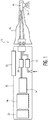
- Figure 1 shows in general a droplet spray teeth cleaning system 10.
- a typical hand-held system for home use will include a body or handle portion 12 in which is located a source of liquid 14.
- a source of liquid 14 In one arrangement, air and the liquid are moved to a head portion 16 of the system by pumps 20-22.
- the liquid and gas are directed to a spray assembly 18 in which the gas stream produces and accelerates liquid droplets to a desired velocity as they move out of a nozzle 24 at the end of the head portion to a desired location on the teeth.
- the droplets have a size range of 10-15 mm and are accelerated to a velocity of approximately 30 meters per second.
- the head portion 16 is arranged to be replaceable relative to the handle portion, which includes sources of gas and liquid, the electronic control portion 24 and the power supply 23 for the system, as well as a user interface 25, with an on/off switch 30.
- a guidance tip/member which is located at the forward end of the head portion 16 for correctly positioning the spray nozzle 24 within the mouth relative to the teeth, in order to accomplish effective cleaning without damaging the tissue or gums of the user. It should be understood that the guidance member described and shown can be used with a variety of droplet spray cleaning systems.
- the head portion of the cleaning device includes a neck 36, which could be rigid or flexible, at the end of which is a spray nozzle 38, through which the accelerated liquid droplets are directed.
- a conical or approximately spherical element 40 which includes a spray opening 42, located a small distance, within the range of 1-15 mm, and more preferably 3-8 mm, from nozzle opening 38.
- the guidance member is made from a soft pliable material, such as rubber, which will not harm gums or other soft tissue.
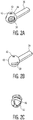
- openings in the conical/spherical member 40 are provided around the periphery thereof. These openings could be of various configurations, as shown in Figures 2A-2C , including spaced parabolic openings 48 in Figure 2A , spaced horizontal slots 50 in Figure 2B or spaced vertical slots 52 in Figure 2C , which connect to spray opening 42. These openings are for the purpose of allowing venting of liquid, and optionally gas, during operation of the system, to prevent pooling of liquid around the nozzle.
- guidance member 40 is curved so as to fit readily between adjacent teeth and the gums, thus readily locating the interproximal area of the teeth for the user.
- the diameter of the spray opening 42 is such that it is slightly larger than the desired footprint of the spray on the teeth. Further, the distance between the guidance member 40 and spray nozzle 38 provides a safe stand-off distance between the spray as it emerges from the nozzle and the teeth. In operation, the user will simply press the guidance member against the teeth, thereby guaranteeing a safe stand-off distance for all cleaning, as well as proper interproximal location when located between the teeth. The guidance member can be moved sideways to locate the spray accurately onto the front surface of the teeth as well.
- a guidance tip member which is located at the end of a spray head assembly portion of a droplet spray teeth cleaning system.
- This arrangement informs the user of the location of the spray relative to the teeth and gums, and reliably positions the spray for interproximal cleaning, as well as the front portions of the teeth.
- the location of the spray assembly is difficult for the user to ascertain without a guidance member since the location of the spray is often not clearly and precisely recognizable by a sensory feel of the spray.
- the guidance member disclosed herein could be used with a hand-held portion of a tethered droplet spray cleaning system as well as a stand-alone hand held unit, as shown in Figure 1 . Further, the guidance member can be used with various droplet spray teeth cleaning systems/devices, including those which are not gas assisted, i.e. those which do not use gas to produce and accelerate the liquid droplets.
Landscapes
- Health & Medical Sciences (AREA)
- Dentistry (AREA)
- Epidemiology (AREA)
- Life Sciences & Earth Sciences (AREA)
- Animal Behavior & Ethology (AREA)
- General Health & Medical Sciences (AREA)
- Public Health (AREA)
- Veterinary Medicine (AREA)
- Cleaning By Liquid Or Steam (AREA)
- Dental Tools And Instruments Or Auxiliary Dental Instruments (AREA)
Description
- This invention relates generally to liquid droplet spray teeth cleaning systems, and more particularly concerns a droplet spray portion of the teeth cleaning system which includes a guidance tip for properly locating the droplet spray relative to the teeth.
- Droplet spray teeth cleaning systems are generally known, and various droplet spray systems are described in several patents and published patent publications. One such patent publication is
WO200507034 - Many of these devices are designed for home use, which requires the user himself/herself to properly locate the spray tip of the device relative to the teeth, so that the spray reaches the desired area of the teeth. This has proven to be a challenge, particularly locating the spray on the interproximal spaces between the teeth. It is difficult for the user to properly locate the spray tip because the spray itself cannot be directly felt by the user.
-
US 5 890 898 A discloses a droplet spray system including a splash guard. Patent publicationWO 2007/101210 A2 with date of priority 27.02.2006 and date of publication 07.09.2007 discloses a similar spray assembly. - It is thus desirable that a droplet spray system include a locating/guidance tip assembly to position the droplet spray properly for effective cleaning, particularly over the interproximal area, but also over the front surface of the teeth as well. In addition, the distance between the origin of the spray and the teeth should be properly controlled for optimal efficiency as well as safety. The spray nozzle cannot be too close, which might cause damage to the gums and other tissues, but also cannot be too far away, as this results in a decrease in efficacy. The guidance tip should thus be arranged to provide both distance and location functions of the device relative to the teeth.
- Furthermore, in some cases, it is important to be able to safely and effectively accommodate teeth braces with a droplet spray cleaning system.
- Accordingly the present invention is a spray assembly for a droplet spray system for cleaning teeth, comprising: a spray assembly for use with a droplet spray teeth cleaning system having a head portion including a rigid or flexible neck, at the end of which is a spray nozzle through which a spray of liquid is directed to the teeth for cleaning thereof and a guidance member at the very end of the neck, which is configured to locate the spray on the teeth, wherein the guidance member is in the form of a sphere or cone which partially surrounds the nozzle, wherein the exterior surface of the guidance member is curved so as to fit readily between adjacent teeth and the gums, wherein the guidance member includes a spray opening through which the spray from the nozzle is directed to the teeth, wherein the spray opening of the guidance member is located a distance within a range of 1-15 mm from a nozzle opening of the nozzle, wherein the diameter of the spray opening of the guidance member is such that it is slightly larger than the desired footprint of the spray on the teeth, wherein the conical/spherical guidance member includes other openings which are provided around the periphery thereof, and which allow fluid to escape therethrough, and wherein the guidance member is made from a soft pliable material.
-
Figure 1 is a simple schematic diagram showing in general a droplet spray teeth cleaning system, which includes a spray assembly portion. -
Figures 2A-2C are perspective views of several variations of the spray assembly system of the present invention, in particular a locating/guidance tip assembly. -
Figure 1 shows in general a droplet sprayteeth cleaning system 10. A typical hand-held system for home use will include a body orhandle portion 12 in which is located a source ofliquid 14. In one arrangement, air and the liquid are moved to ahead portion 16 of the system by pumps 20-22. The liquid and gas are directed to aspray assembly 18 in which the gas stream produces and accelerates liquid droplets to a desired velocity as they move out of anozzle 24 at the end of the head portion to a desired location on the teeth. - In one example, the droplets have a size range of 10-15 mm and are accelerated to a velocity of approximately 30 meters per second. Other arrangements, however, with different size droplets and different velocities can be used, for instance, at velocities up to 70 meters per second. In the present embodiment, the
head portion 16 is arranged to be replaceable relative to the handle portion, which includes sources of gas and liquid, theelectronic control portion 24 and thepower supply 23 for the system, as well as auser interface 25, with an on/off switch 30. - What is shown and described herein is a guidance tip/member which is located at the forward end of the
head portion 16 for correctly positioning thespray nozzle 24 within the mouth relative to the teeth, in order to accomplish effective cleaning without damaging the tissue or gums of the user. It should be understood that the guidance member described and shown can be used with a variety of droplet spray cleaning systems. - A preferred embodiment of a guidance member is shown in
Figures 2A-2C . The head portion of the cleaning device includes aneck 36, which could be rigid or flexible, at the end of which is aspray nozzle 38, through which the accelerated liquid droplets are directed. In this embodiment, at the very end ofneck 36, partially surrounding the spray nozzle, is a conical or approximatelyspherical element 40 which includes aspray opening 42, located a small distance, within the range of 1-15 mm, and more preferably 3-8 mm, fromnozzle opening 38. The guidance member is made from a soft pliable material, such as rubber, which will not harm gums or other soft tissue. - Other openings in the conical/
spherical member 40 are provided around the periphery thereof. These openings could be of various configurations, as shown inFigures 2A-2C , including spacedparabolic openings 48 inFigure 2A , spacedhorizontal slots 50 inFigure 2B or spacedvertical slots 52 inFigure 2C , which connect tospray opening 42. These openings are for the purpose of allowing venting of liquid, and optionally gas, during operation of the system, to prevent pooling of liquid around the nozzle. - The exterior surface of
guidance member 40 is curved so as to fit readily between adjacent teeth and the gums, thus readily locating the interproximal area of the teeth for the user. - The diameter of the
spray opening 42 is such that it is slightly larger than the desired footprint of the spray on the teeth. Further, the distance between theguidance member 40 andspray nozzle 38 provides a safe stand-off distance between the spray as it emerges from the nozzle and the teeth. In operation, the user will simply press the guidance member against the teeth, thereby guaranteeing a safe stand-off distance for all cleaning, as well as proper interproximal location when located between the teeth. The guidance member can be moved sideways to locate the spray accurately onto the front surface of the teeth as well. - Hence, a guidance tip member has been disclosed which is located at the end of a spray head assembly portion of a droplet spray teeth cleaning system. This arrangement informs the user of the location of the spray relative to the teeth and gums, and reliably positions the spray for interproximal cleaning, as well as the front portions of the teeth. The location of the spray assembly is difficult for the user to ascertain without a guidance member since the location of the spray is often not clearly and precisely recognizable by a sensory feel of the spray.
- It should be understood that the guidance member disclosed herein could be used with a hand-held portion of a tethered droplet spray cleaning system as well as a stand-alone hand held unit, as shown in
Figure 1 . Further, the guidance member can be used with various droplet spray teeth cleaning systems/devices, including those which are not gas assisted, i.e. those which do not use gas to produce and accelerate the liquid droplets.
Claims (6)
- A spray assembly for a droplet spray system for cleaning teeth, comprising: a spray assembly for use with a droplet spray teeth cleaning system (10) having a head portion (16) including a rigid or flexible neck (36), at the end of which is a spray nozzle (24) through which a spray of liquid is directed to the teeth for cleaning thereof and a guidance member (40) at the very end of the neck (36), which is configured to locate the spray on the teeth, wherein the guidance member (40) is in the form of a sphere or cone which partially surrounds the nozzle (24), wherein the exterior surface of the guidance member (40) is curved so as to fit readily between adjacent teeth and the gums, wherein the guidance member (40) includes a spray opening (42) through which the spray from the nozzle (24) is directed to the teeth, wherein the spray opening (42) of the guidance member (40) is located a distance within a range of 1-15 mm from a nozzle opening (38) of the nozzle (24), wherein the diameter of the spray opening (42) of the guidance member (40) is such that it is slightly larger than the desired footprint of the spray on the teeth, wherein the conical/spherical guidance member (40) includes other openings (48, 50, 52) which are provided around the periphery thereof, and which allow fluid to escape therethrough, and wherein the guidance member (40) is made from a soft pliable material.
- The spray assembly of claim 1, wherein the spray opening (42) of the guidance member (40) is located a distance within a range of 3-8 mm from the nozzle opening (38) of the nozzle (24).
- The spray assembly of claim 1, wherein the guidance member (40) is also configured to provide a safe stand-off distance between the teeth and the spray nozzle (24).
- The spray system of claim 1, wherein the guidance member (40) is configured to locate the spray at an interproximal area of the teeth.
- The spray assembly of claim 1, wherein the spray opening (42) is approximately circular, slightly larger than a desired spray footprint on the teeth, and wherein the other openings (48, 50, 52) are in the form of slots.
- The spray assembly of claim 5, wherein the other openings (48, 50, 52) are in the form of spaced vertical slots (52) which connect to the spray opening (42).
Applications Claiming Priority (2)
| Application Number | Priority Date | Filing Date | Title |
|---|---|---|---|
| US81822406P | 2006-06-30 | 2006-06-30 | |
| PCT/IB2007/053402 WO2008001337A2 (en) | 2006-06-30 | 2007-08-24 | A locating/guidance tip assembly for a liquid droplet spray teeth cleaning system |
Publications (2)
| Publication Number | Publication Date |
|---|---|
| EP2037836A2 EP2037836A2 (en) | 2009-03-25 |
| EP2037836B1 true EP2037836B1 (en) | 2017-03-22 |
Family
ID=38846077
Family Applications (1)
| Application Number | Title | Priority Date | Filing Date |
|---|---|---|---|
| EP07826130.2A Active EP2037836B1 (en) | 2006-06-30 | 2007-08-24 | A locating/guidance tip assembly for a liquid droplet spray teeth cleaning system |
Country Status (3)
| Country | Link |
|---|---|
| EP (1) | EP2037836B1 (en) |
| ES (1) | ES2628024T3 (en) |
| PL (1) | PL2037836T3 (en) |
Citations (1)
| Publication number | Priority date | Publication date | Assignee | Title |
|---|---|---|---|---|
| WO2007101210A2 (en) * | 2006-02-27 | 2007-09-07 | Water Pik, Inc. | Tip for oral irrigator |
-
2007
- 2007-08-24 EP EP07826130.2A patent/EP2037836B1/en active Active
- 2007-08-24 PL PL07826130T patent/PL2037836T3/en unknown
- 2007-08-24 ES ES07826130.2T patent/ES2628024T3/en active Active
Patent Citations (1)
| Publication number | Priority date | Publication date | Assignee | Title |
|---|---|---|---|---|
| WO2007101210A2 (en) * | 2006-02-27 | 2007-09-07 | Water Pik, Inc. | Tip for oral irrigator |
Also Published As
| Publication number | Publication date |
|---|---|
| EP2037836A2 (en) | 2009-03-25 |
| PL2037836T3 (en) | 2017-09-29 |
| ES2628024T3 (en) | 2017-08-01 |
Similar Documents
| Publication | Publication Date | Title |
|---|---|---|
| US9204946B2 (en) | Locating/guidance tip assembly for a liquid droplet spray teeth cleaning system | |
| US9597168B2 (en) | Guidance assembly tip for a liquid droplet spray teeth cleaning appliance | |
| EP2967775B1 (en) | An oral care appliance using a jet-type fluid flow and mechanical action | |
| EP2893900B1 (en) | Non-pressurized system for creating liquid droplets in a dental cleaning appliance | |
| EP3212121B1 (en) | Adjustable assembly and nozzle for providing various liquid/air output flow patterns | |
| EP0645987B1 (en) | Apparatus for controlling the aerosol envelope | |
| WO2002028350A3 (en) | Nozzle for ultrasound and wound treatment | |
| CN102470026B (en) | Atomized liquid oral cleaning appliance | |
| EP3878398A3 (en) | Dental treatment apparatus | |
| US5833675A (en) | Irrigator device | |
| WO2007146113A2 (en) | Self-contained disposable micro-abrasive blasting tip for dental applications and method | |
| CN112567283A (en) | Endoscope with a detachable handle | |
| JP2008525095A (en) | Gas assist system for droplet generation in oral care system | |
| JP2023535094A (en) | Dental suction device and dental suction device and instrument assembly | |
| KR20190072041A (en) | Sterilization Apparatus with Plasma Jet Spray Structure | |
| KR20100109926A (en) | Protective assembly for a compressed gas interproximal cleaner | |
| CN114449976A (en) | Directs irrigation fluid flow to periodontal pockets in subject's mouth | |
| DK1720666T3 (en) | Surface cleaning head | |
| US20110223555A1 (en) | Jet device | |
| KR101424760B1 (en) | Handpiece | |
| US20110139831A1 (en) | Spray tube with safety feature | |
| EP2037836A2 (en) | A locating/guidance tip assembly for a liquid droplet spray teeth cleaning system | |
| CN219721680U (en) | Skin irrigation handpiece with improved delivery head | |
| KR20210078988A (en) | Dental instrument contamination prevention unit with central ultrasonic transverse unit | |
| JP2721321B2 (en) | Dental treatment tools |
Legal Events
| Date | Code | Title | Description |
|---|---|---|---|
| PUAI | Public reference made under article 153(3) epc to a published international application that has entered the european phase |
Free format text: ORIGINAL CODE: 0009012 |
|
| 17P | Request for examination filed |
Effective date: 20090130 |
|
| AK | Designated contracting states |
Kind code of ref document: A2 Designated state(s): AT BE BG CH CY CZ DE DK EE ES FI FR GB GR HU IE IS IT LI LT LU LV MC MT NL PL PT RO SE SI SK TR |
|
| DAX | Request for extension of the european patent (deleted) | ||
| 17Q | First examination report despatched |
Effective date: 20120312 |
|
| RAP1 | Party data changed (applicant data changed or rights of an application transferred) |
Owner name: KONINKLIJKE PHILIPS N.V. |
|
| GRAP | Despatch of communication of intention to grant a patent |
Free format text: ORIGINAL CODE: EPIDOSNIGR1 |
|
| INTG | Intention to grant announced |
Effective date: 20161107 |
|
| GRAS | Grant fee paid |
Free format text: ORIGINAL CODE: EPIDOSNIGR3 |
|
| GRAA | (expected) grant |
Free format text: ORIGINAL CODE: 0009210 |
|
| AK | Designated contracting states |
Kind code of ref document: B1 Designated state(s): AT BE BG CH CY CZ DE DK EE ES FI FR GB GR HU IE IS IT LI LT LU LV MC MT NL PL PT RO SE SI SK TR |
|
| REG | Reference to a national code |
Ref country code: GB Ref legal event code: FG4D |
|
| REG | Reference to a national code |
Ref country code: CH Ref legal event code: EP |
|
| REG | Reference to a national code |
Ref country code: AT Ref legal event code: REF Ref document number: 876934 Country of ref document: AT Kind code of ref document: T Effective date: 20170415 |
|
| REG | Reference to a national code |
Ref country code: IE Ref legal event code: FG4D |
|
| REG | Reference to a national code |
Ref country code: DE Ref legal event code: R096 Ref document number: 602007050315 Country of ref document: DE |
|
| REG | Reference to a national code |
Ref country code: NL Ref legal event code: MP Effective date: 20170322 |
|
| PG25 | Lapsed in a contracting state [announced via postgrant information from national office to epo] |
Ref country code: FI Free format text: LAPSE BECAUSE OF FAILURE TO SUBMIT A TRANSLATION OF THE DESCRIPTION OR TO PAY THE FEE WITHIN THE PRESCRIBED TIME-LIMIT Effective date: 20170322 Ref country code: LT Free format text: LAPSE BECAUSE OF FAILURE TO SUBMIT A TRANSLATION OF THE DESCRIPTION OR TO PAY THE FEE WITHIN THE PRESCRIBED TIME-LIMIT Effective date: 20170322 Ref country code: GR Free format text: LAPSE BECAUSE OF FAILURE TO SUBMIT A TRANSLATION OF THE DESCRIPTION OR TO PAY THE FEE WITHIN THE PRESCRIBED TIME-LIMIT Effective date: 20170623 |
|
| REG | Reference to a national code |
Ref country code: ES Ref legal event code: FG2A Ref document number: 2628024 Country of ref document: ES Kind code of ref document: T3 Effective date: 20170801 |
|
| REG | Reference to a national code |
Ref country code: LT Ref legal event code: MG4D |
|
| REG | Reference to a national code |
Ref country code: AT Ref legal event code: MK05 Ref document number: 876934 Country of ref document: AT Kind code of ref document: T Effective date: 20170322 |
|
| REG | Reference to a national code |
Ref country code: FR Ref legal event code: PLFP Year of fee payment: 11 |
|
| PG25 | Lapsed in a contracting state [announced via postgrant information from national office to epo] |
Ref country code: LV Free format text: LAPSE BECAUSE OF FAILURE TO SUBMIT A TRANSLATION OF THE DESCRIPTION OR TO PAY THE FEE WITHIN THE PRESCRIBED TIME-LIMIT Effective date: 20170322 Ref country code: BG Free format text: LAPSE BECAUSE OF FAILURE TO SUBMIT A TRANSLATION OF THE DESCRIPTION OR TO PAY THE FEE WITHIN THE PRESCRIBED TIME-LIMIT Effective date: 20170622 Ref country code: SE Free format text: LAPSE BECAUSE OF FAILURE TO SUBMIT A TRANSLATION OF THE DESCRIPTION OR TO PAY THE FEE WITHIN THE PRESCRIBED TIME-LIMIT Effective date: 20170322 |
|
| PG25 | Lapsed in a contracting state [announced via postgrant information from national office to epo] |
Ref country code: NL Free format text: LAPSE BECAUSE OF FAILURE TO SUBMIT A TRANSLATION OF THE DESCRIPTION OR TO PAY THE FEE WITHIN THE PRESCRIBED TIME-LIMIT Effective date: 20170322 |
|
| PG25 | Lapsed in a contracting state [announced via postgrant information from national office to epo] |
Ref country code: SK Free format text: LAPSE BECAUSE OF FAILURE TO SUBMIT A TRANSLATION OF THE DESCRIPTION OR TO PAY THE FEE WITHIN THE PRESCRIBED TIME-LIMIT Effective date: 20170322 Ref country code: RO Free format text: LAPSE BECAUSE OF FAILURE TO SUBMIT A TRANSLATION OF THE DESCRIPTION OR TO PAY THE FEE WITHIN THE PRESCRIBED TIME-LIMIT Effective date: 20170322 Ref country code: CZ Free format text: LAPSE BECAUSE OF FAILURE TO SUBMIT A TRANSLATION OF THE DESCRIPTION OR TO PAY THE FEE WITHIN THE PRESCRIBED TIME-LIMIT Effective date: 20170322 Ref country code: AT Free format text: LAPSE BECAUSE OF FAILURE TO SUBMIT A TRANSLATION OF THE DESCRIPTION OR TO PAY THE FEE WITHIN THE PRESCRIBED TIME-LIMIT Effective date: 20170322 Ref country code: EE Free format text: LAPSE BECAUSE OF FAILURE TO SUBMIT A TRANSLATION OF THE DESCRIPTION OR TO PAY THE FEE WITHIN THE PRESCRIBED TIME-LIMIT Effective date: 20170322 |
|
| PGFP | Annual fee paid to national office [announced via postgrant information from national office to epo] |
Ref country code: IT Payment date: 20170825 Year of fee payment: 11 |
|
| PG25 | Lapsed in a contracting state [announced via postgrant information from national office to epo] |
Ref country code: PT Free format text: LAPSE BECAUSE OF FAILURE TO SUBMIT A TRANSLATION OF THE DESCRIPTION OR TO PAY THE FEE WITHIN THE PRESCRIBED TIME-LIMIT Effective date: 20170724 Ref country code: IS Free format text: LAPSE BECAUSE OF FAILURE TO SUBMIT A TRANSLATION OF THE DESCRIPTION OR TO PAY THE FEE WITHIN THE PRESCRIBED TIME-LIMIT Effective date: 20170722 |
|
| PGFP | Annual fee paid to national office [announced via postgrant information from national office to epo] |
Ref country code: PL Payment date: 20170824 Year of fee payment: 11 |
|
| REG | Reference to a national code |
Ref country code: DE Ref legal event code: R097 Ref document number: 602007050315 Country of ref document: DE |
|
| PLBE | No opposition filed within time limit |
Free format text: ORIGINAL CODE: 0009261 |
|
| STAA | Information on the status of an ep patent application or granted ep patent |
Free format text: STATUS: NO OPPOSITION FILED WITHIN TIME LIMIT |
|
| PG25 | Lapsed in a contracting state [announced via postgrant information from national office to epo] |
Ref country code: DK Free format text: LAPSE BECAUSE OF FAILURE TO SUBMIT A TRANSLATION OF THE DESCRIPTION OR TO PAY THE FEE WITHIN THE PRESCRIBED TIME-LIMIT Effective date: 20170322 |
|
| PGFP | Annual fee paid to national office [announced via postgrant information from national office to epo] |
Ref country code: DE Payment date: 20171030 Year of fee payment: 11 |
|
| 26N | No opposition filed |
Effective date: 20180102 |
|
| PG25 | Lapsed in a contracting state [announced via postgrant information from national office to epo] |
Ref country code: SI Free format text: LAPSE BECAUSE OF FAILURE TO SUBMIT A TRANSLATION OF THE DESCRIPTION OR TO PAY THE FEE WITHIN THE PRESCRIBED TIME-LIMIT Effective date: 20170322 |
|
| REG | Reference to a national code |
Ref country code: CH Ref legal event code: PL |
|
| PG25 | Lapsed in a contracting state [announced via postgrant information from national office to epo] |
Ref country code: MC Free format text: LAPSE BECAUSE OF FAILURE TO SUBMIT A TRANSLATION OF THE DESCRIPTION OR TO PAY THE FEE WITHIN THE PRESCRIBED TIME-LIMIT Effective date: 20170322 |
|
| PG25 | Lapsed in a contracting state [announced via postgrant information from national office to epo] |
Ref country code: CH Free format text: LAPSE BECAUSE OF NON-PAYMENT OF DUE FEES Effective date: 20170831 Ref country code: LI Free format text: LAPSE BECAUSE OF NON-PAYMENT OF DUE FEES Effective date: 20170831 |
|
| REG | Reference to a national code |
Ref country code: IE Ref legal event code: MM4A |
|
| REG | Reference to a national code |
Ref country code: BE Ref legal event code: MM Effective date: 20170831 |
|
| PG25 | Lapsed in a contracting state [announced via postgrant information from national office to epo] |
Ref country code: LU Free format text: LAPSE BECAUSE OF NON-PAYMENT OF DUE FEES Effective date: 20170824 |
|
| PG25 | Lapsed in a contracting state [announced via postgrant information from national office to epo] |
Ref country code: IE Free format text: LAPSE BECAUSE OF NON-PAYMENT OF DUE FEES Effective date: 20170824 |
|
| REG | Reference to a national code |
Ref country code: FR Ref legal event code: PLFP Year of fee payment: 12 |
|
| PG25 | Lapsed in a contracting state [announced via postgrant information from national office to epo] |
Ref country code: BE Free format text: LAPSE BECAUSE OF NON-PAYMENT OF DUE FEES Effective date: 20170831 |
|
| PG25 | Lapsed in a contracting state [announced via postgrant information from national office to epo] |
Ref country code: MT Free format text: LAPSE BECAUSE OF NON-PAYMENT OF DUE FEES Effective date: 20170824 |
|
| REG | Reference to a national code |
Ref country code: DE Ref legal event code: R119 Ref document number: 602007050315 Country of ref document: DE |
|
| PG25 | Lapsed in a contracting state [announced via postgrant information from national office to epo] |
Ref country code: HU Free format text: LAPSE BECAUSE OF FAILURE TO SUBMIT A TRANSLATION OF THE DESCRIPTION OR TO PAY THE FEE WITHIN THE PRESCRIBED TIME-LIMIT; INVALID AB INITIO Effective date: 20070824 |
|
| PG25 | Lapsed in a contracting state [announced via postgrant information from national office to epo] |
Ref country code: DE Free format text: LAPSE BECAUSE OF NON-PAYMENT OF DUE FEES Effective date: 20190301 Ref country code: IT Free format text: LAPSE BECAUSE OF NON-PAYMENT OF DUE FEES Effective date: 20180824 |
|
| REG | Reference to a national code |
Ref country code: ES Ref legal event code: FD2A Effective date: 20190918 |
|
| PG25 | Lapsed in a contracting state [announced via postgrant information from national office to epo] |
Ref country code: CY Free format text: LAPSE BECAUSE OF NON-PAYMENT OF DUE FEES Effective date: 20170322 Ref country code: ES Free format text: LAPSE BECAUSE OF NON-PAYMENT OF DUE FEES Effective date: 20180825 |
|
| PG25 | Lapsed in a contracting state [announced via postgrant information from national office to epo] |
Ref country code: PL Free format text: LAPSE BECAUSE OF NON-PAYMENT OF DUE FEES Effective date: 20180824 |
|
| PGFP | Annual fee paid to national office [announced via postgrant information from national office to epo] |
Ref country code: TR Payment date: 20210811 Year of fee payment: 15 |
|
| PGFP | Annual fee paid to national office [announced via postgrant information from national office to epo] |
Ref country code: GB Payment date: 20230822 Year of fee payment: 17 |
|
| PG25 | Lapsed in a contracting state [announced via postgrant information from national office to epo] |
Ref country code: TR Free format text: LAPSE BECAUSE OF NON-PAYMENT OF DUE FEES Effective date: 20220824 |
|
| GBPC | Gb: european patent ceased through non-payment of renewal fee |
Effective date: 20240824 |
|
| PG25 | Lapsed in a contracting state [announced via postgrant information from national office to epo] |
Ref country code: GB Free format text: LAPSE BECAUSE OF NON-PAYMENT OF DUE FEES Effective date: 20240824 |
|
| PGFP | Annual fee paid to national office [announced via postgrant information from national office to epo] |
Ref country code: FR Payment date: 20250825 Year of fee payment: 19 |