EP2037464A2 - Plastic bobbin with creep prevention feature - Google Patents
Plastic bobbin with creep prevention feature Download PDFInfo
- Publication number
- EP2037464A2 EP2037464A2 EP08163675A EP08163675A EP2037464A2 EP 2037464 A2 EP2037464 A2 EP 2037464A2 EP 08163675 A EP08163675 A EP 08163675A EP 08163675 A EP08163675 A EP 08163675A EP 2037464 A2 EP2037464 A2 EP 2037464A2
- Authority
- EP
- European Patent Office
- Prior art keywords
- bobbin
- solenoid
- resilient portion
- coil
- relatively
- Prior art date
- Legal status (The legal status is an assumption and is not a legal conclusion. Google has not performed a legal analysis and makes no representation as to the accuracy of the status listed.)
- Withdrawn
Links
- 239000004033 plastic Substances 0.000 title claims abstract description 7
- 230000002265 prevention Effects 0.000 title 1
- 239000004677 Nylon Substances 0.000 claims abstract description 4
- 229920001778 nylon Polymers 0.000 claims abstract description 4
- 238000006073 displacement reaction Methods 0.000 claims abstract 3
- 239000000463 material Substances 0.000 claims description 10
- 238000002347 injection Methods 0.000 claims description 2
- 239000007924 injection Substances 0.000 claims description 2
- 239000002991 molded plastic Substances 0.000 claims description 2
- 229910000831 Steel Inorganic materials 0.000 description 10
- 239000010959 steel Substances 0.000 description 10
- 239000000243 solution Substances 0.000 description 4
- 230000000694 effects Effects 0.000 description 3
- 230000004907 flux Effects 0.000 description 3
- 230000007704 transition Effects 0.000 description 3
- 238000002788 crimping Methods 0.000 description 2
- 239000012530 fluid Substances 0.000 description 2
- 230000004048 modification Effects 0.000 description 2
- 238000012986 modification Methods 0.000 description 2
- 238000013459 approach Methods 0.000 description 1
- 239000003610 charcoal Substances 0.000 description 1
- 230000002860 competitive effect Effects 0.000 description 1
- 239000000470 constituent Substances 0.000 description 1
- 238000013016 damping Methods 0.000 description 1
- 239000000446 fuel Substances 0.000 description 1
- 239000007788 liquid Substances 0.000 description 1
- 230000007774 longterm Effects 0.000 description 1
- 230000007257 malfunction Effects 0.000 description 1
- 230000010512 thermal transition Effects 0.000 description 1
Images
Classifications
-
- H—ELECTRICITY
- H01—ELECTRIC ELEMENTS
- H01F—MAGNETS; INDUCTANCES; TRANSFORMERS; SELECTION OF MATERIALS FOR THEIR MAGNETIC PROPERTIES
- H01F7/00—Magnets
- H01F7/06—Electromagnets; Actuators including electromagnets
- H01F7/08—Electromagnets; Actuators including electromagnets with armatures
- H01F7/126—Supporting or mounting
-
- H—ELECTRICITY
- H01—ELECTRIC ELEMENTS
- H01F—MAGNETS; INDUCTANCES; TRANSFORMERS; SELECTION OF MATERIALS FOR THEIR MAGNETIC PROPERTIES
- H01F5/00—Coils
- H01F5/02—Coils wound on non-magnetic supports, e.g. formers
Definitions
- the present disclosure relates generally to solenoids, and particularly to solenoid valves.
- Solenoids are used in a myriad of applications in the automotive industry. For example, solenoids may be used for high power switches with a lower power control signal. Solenoids are also used in automated or remote valves, such as a canister vent solenoid associated with evaporative emission control systems. Such solenoid valves may be used to control the flow of a variety of fluids or gasses. For example, in the context of a canister vent solenoid, the solenoid valve may be used to control the flow of fuel vapors into a charcoal canister. Solenoid valves may be similarly used to control the flow of liquids and vapors for other vehicle systems.
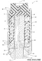
- FIG. 1 is a broken, perspective cross-sectional view of the actuator portion of an automotive oil control valve assembly embodying the present invention
- the present invention is particularly well adapted for use in an automotive oil control valve, and will be described in that context.
- the present invention provides a cheap (negligible additional cost) and permanent solution.
- the present invention proposes a hinge-like feature at the base of the bobbin that will damp the effect of the force exerted during the crimping operation (of the frame) during assembly. Over time, as the plastic yields beneath the steel frame, the hinge will spring-back (because it will not reach its yield strength) and retain rigidity of the assembly.
- the actuator assembly 10 for use with an automotive oil control valve 12 (shown partially) is illustrated.
- the actuator assembly 10 includes a subassembly including a bobbin 14 formed in one piece of injection molded plastic such as nylon.
- the bobbin has a main or base portion 16 which carries an electromagnetic coil 18 on the outer surface thereof.
- One end of the bobbin 14 is closed to define an electrical connector terminal interface as well as mounting features for a secondary magnetic flux plate 20 (steel).
- the bobbin 14 is overmolded with non-conductive plastic-like material 22.
- the subassembly, including the bobbin 14 and the overmolding material 22 is disposed within a generally cylindrical steel can or magnetic frame 24, the inner diameter surface of which is in close proximity with the secondary plate 20.
- the open end of the bobbin 14 defines a skirt-shaped portion 26 which extends axially from the base portion 16.
- the base portion 16 and skirt portion 26 are integrally formed of nylon or other suitable material.
- the base portion 16 of the bobbin 14 is dimensioned and configured to be relatively rigid while the skirt portion 26 is dimensioned to be relatively resilient, particularly in the axial direction (A-A).
- a primary magnetic flux plate 28 (steel) is press fit within the frame 24 and includes an annular opening concentric with the central opening of the bobbin 14 for receiving a generally cylindrical/tubular cup guide 30.
- Cup guide 30 has a flange 32 extending radially from the lower portion thereof which is clamped in position by a steel washer 34.
- An inner primary magnetic flux plate 36 (steel) is disposed within the cup guide 30.
- a steel housing 38 extends axially from the frame 24 to become the oil control valve 12.
- An armature/plunger 40 is slidably disposed within the guide cup 30 and defines an axially extending damping passageway 42 therethrough.
- a steel spool valve 44 extends through housing 38 into valve 12.
- the axial ends of the frame 24 are crimped radially inwardly to abut a radial step 46 formed in overmolding material 22 and a radial step 48 formed in housing 38 to apply an axial compressive load to the bobbin 14, inter alia.
- the skirt portion 26 of the bobbin is formed as upper and lower axially spaced rings 50 and 52, respectively, and an axially intermediate thin-walled section or web 54 integrally formed therewith.
- the upper portion of the web 54 transitions into upper ring 50 to define a downwardly (axially) facing abutment surface 56.
- the lower portion of the web 54 transitions into the lower ring 52 to define an upwardly (axially) facing abutment surface 58.
- Abutment surfaces 56 and 28 are thus axially spaced when the bobbin is in the relaxed position as depicted in Figure 17.
- the point of transition of the main portion 16 of the bobbin 14 into the skirt portion 26 also defines opposed, axially spaced abutment surfaces 60 and 62, respectively, intersaced by a web 63.
- the rings 50 and 52 as well as the web 54 are configured to ensure that the localized material forming the skirt portion 26 never exceed its characteristic yield point and, as a result, will maintain the bobbin 14 under compressive loading during thermal transition induced shrinkage and long term load induced creeping of the bobbin material.
Landscapes
- Physics & Mathematics (AREA)
- Electromagnetism (AREA)
- Engineering & Computer Science (AREA)
- Power Engineering (AREA)
- Magnetically Actuated Valves (AREA)
Abstract
A solenoid actuated valve (12) includes a plastic nylon bobbin (14) which has a relatively rigid portion (16) which supports the electrical actuation coil (18) and a separate, relatively resilient portion (26), which is integrally formed with the rigid portion of the bobbin for the mounting thereof. An armature (40) is positioned for reciprocating displacement within a central passageway of the bobbin in response to selective energization of the coil. A spool valve is operatively connected for movement with the armature. A frame assembly (24) supports the solenoid valve and continuously compressively loads the resilient portion of the bobbin within a non-plastic range of deformation.
Description
- The present disclosure relates generally to solenoids, and particularly to solenoid valves.
- Solenoids are used in a myriad of applications in the automotive industry. For example, solenoids may be used for high power switches with a lower power control signal. Solenoids are also used in automated or remote valves, such as a canister vent solenoid associated with evaporative emission control systems. Such solenoid valves may be used to control the flow of a variety of fluids or gasses. For example, in the context of a canister vent solenoid, the solenoid valve may be used to control the flow of fuel vapors into a charcoal canister. Solenoid valves may be similarly used to control the flow of liquids and vapors for other vehicle systems.
- These and other features and advantages of this invention will become apparent upon reading the following specification, which, along with the drawings, describes preferred and alternative embodiments of the invention in detail.
- The present invention will now be described, by way of example, with reference to the accompanying drawings, in which:
- The figure, is a broken, perspective cross-sectional view of the actuator portion of an automotive oil control valve assembly embodying the present invention;
- Although the drawings represent embodiments of the present invention, the drawings are not necessarily to scale and certain features may be exaggerated in order to illustrate and explain the present invention. The exemplification set forth herein illustrates an embodiment of the invention, in one form, and such exemplifications are not to be construed as limiting the scope of the invention in any manner.
- Although suitable for many automotive and non-automotive applications, the present invention is particularly well adapted for use in an automotive oil control valve, and will be described in that context.
- In previous automotive oil control valve designs, it was noted that the bobbin can become loose after durability tests and engine tests. It is surmised that the bobbins can become loose due to the difference in thermal expansion coefficients between steel and plastic, that creates a creeping effect or deformation in the plastic. This can result in objectionable rattling, fluid leaks of malfunction of the device. Benchmarking demonstrated that existing competitive designs have similar design issues which were addressed by varying solutions such as press fits, separate spring washers and crimping steel-to-steel surfaces. Although partially effective solutions, these approaches prove to be expensive and can introduce new failure modes. An additional solution is the use of a crush rib which can only retard or lessen (but not fully resolve) the effect.
- The present invention provides a cheap (negligible additional cost) and permanent solution.
- The present invention proposes a hinge-like feature at the base of the bobbin that will damp the effect of the force exerted during the crimping operation (of the frame) during assembly. Over time, as the plastic yields beneath the steel frame, the hinge will spring-back (because it will not reach its yield strength) and retain rigidity of the assembly.
- Referring to the figure , a
solenoid actuator assembly 10 for use with an automotive oil control valve 12 (shown partially) is illustrated. Theactuator assembly 10 includes a subassembly including abobbin 14 formed in one piece of injection molded plastic such as nylon. The bobbin has a main orbase portion 16 which carries anelectromagnetic coil 18 on the outer surface thereof. One end of thebobbin 14 is closed to define an electrical connector terminal interface as well as mounting features for a secondary magnetic flux plate 20 (steel). Thebobbin 14 is overmolded with non-conductive plastic-like material 22. - The subassembly, including the
bobbin 14 and theovermolding material 22 is disposed within a generally cylindrical steel can ormagnetic frame 24, the inner diameter surface of which is in close proximity with thesecondary plate 20. The open end of thebobbin 14 defines a skirt-shaped portion 26 which extends axially from thebase portion 16. Thebase portion 16 andskirt portion 26 are integrally formed of nylon or other suitable material. Thebase portion 16 of thebobbin 14 is dimensioned and configured to be relatively rigid while theskirt portion 26 is dimensioned to be relatively resilient, particularly in the axial direction (A-A). - A primary magnetic flux plate 28 (steel) is press fit within the
frame 24 and includes an annular opening concentric with the central opening of thebobbin 14 for receiving a generally cylindrical/tubular cup guide 30.Cup guide 30 has aflange 32 extending radially from the lower portion thereof which is clamped in position by asteel washer 34. An inner primary magnetic flux plate 36 (steel) is disposed within thecup guide 30. - A
steel housing 38 extends axially from theframe 24 to become theoil control valve 12. An armature/plunger 40 is slidably disposed within theguide cup 30 and defines an axially extendingdamping passageway 42 therethrough. Asteel spool valve 44 extends throughhousing 38 intovalve 12. - The axial ends of the
frame 24 are crimped radially inwardly to abut aradial step 46 formed in overmoldingmaterial 22 and aradial step 48 formed inhousing 38 to apply an axial compressive load to thebobbin 14, inter alia. - The
skirt portion 26 of the bobbin is formed as upper and lower axially spacedrings web 54 integrally formed therewith. As best viewed in Figures 17 and 18, the upper portion of theweb 54 transitions intoupper ring 50 to define a downwardly (axially) facing abutment surface 56. Likewise, the lower portion of theweb 54 transitions into thelower ring 52 to define an upwardly (axially) facing abutment surface 58. Abutment surfaces 56 and 28 are thus axially spaced when the bobbin is in the relaxed position as depicted in Figure 17. The point of transition of themain portion 16 of thebobbin 14 into theskirt portion 26 also defines opposed, axially spaced abutment surfaces 60 and 62, respectively, intersaced by a web 63. - Although the drawing represent an embodiment of the present invention, the drawing is not necessarily to scale and certain features may be exaggerated in order to illustrate and explain the present invention. The exemplification set forth herein illustrates an embodiment of the invention, in one form, and such exemplifications are not to be construed as limiting the scope of the invention in any manner.
- The
rings web 54 are configured to ensure that the localized material forming theskirt portion 26 never exceed its characteristic yield point and, as a result, will maintain thebobbin 14 under compressive loading during thermal transition induced shrinkage and long term load induced creeping of the bobbin material. - It is to be understood that the invention has been described with reference to specific embodiments and variations to provide the features and advantages previously described and that the embodiments are susceptible of modification as will be apparent to those skilled in the art.
- Furthermore, it is contemplated that many alternative, common inexpensive materials can be employed to construct the basis constituent components. Accordingly, the forgoing is not to be construed in a limiting sense.
- The invention has been described in an illustrative manner, and it is to be understood that the terminology, which has been used is intended to be in the nature of words of description rather than of limitation.
- Obviously, many modifications and variations of the present invention are possible in light of the above teachings. For example, ... It is, therefore, to be understood that within the scope of the appended claims, wherein reference numerals are merely for illustrative purposes and convenience and are not in any way limiting, the invention, which is defined by the following claims as interpreted according to the principles of patent law, including the Doctrine of Equivalents, may be practiced otherwise than is specifically described.
- The specification of the below listed U.S. Patents and applications are incorporated herein by reference:
-
-
-
-
-
-
-
-
-
-
-
-
-
Claims (10)
- A solenoid valve comprising;a bobbin including a relatively rigid portion configured to support a coil and a relatively resilient portion integrally formed with said rigid portion;an armature disposed for reciprocating displacement within said bobbin in response to selective electrical energization of said coil;valve means operatively connected to said armature; anda frame assembly operative to continuously compressively load the resilient portion of said bobbin.
- The solenoid valve of claim 1, wherein said bobbin is formed of homogeneous material.
- The solenoid valve of claim 2, wherein said homogeneous material is injection molded plastic.
- The solenoid valve of claim 2, wherein said homogeneous material is nylon.
- A solenoid comprising:a bobbin including a relatively rigid portion configured to support a coil and a relatively resilient portion integrally formed with said rigid portion;an armature disposed for reciprocating displacement within said bobbin in response to selective electrical energization of said coil; anda frame assembly operative to compressively load the resilient portion of the bobbin.
- The solenoid of claim 5, wherein said frame assembly compressively loads the resilient portion of the bobbin within a non-plastic region of deformation.
- The solenoid of claim 5, wherein the resilient portion of the bobbin comprises at least one thin-wall section.
- The solenoid of claim 7, wherein said thin-wall section is circumferentially continuous.
- The solenoid of claim 5, wherein said bobbin comprises one or more abutment surfaces operative to limit axial distension of said bobbin in response to application induced loading.
- The solenoid of claim 5, wherein the resilient portion of the bobbin defines opposed, axially spaced abutment surfaces straddling a thin-wall section.
Applications Claiming Priority (1)
| Application Number | Priority Date | Filing Date | Title |
|---|---|---|---|
| US11/900,413 US20090065723A1 (en) | 2007-09-11 | 2007-09-11 | Plastic bobbin with creep prevention feature |
Publications (1)
| Publication Number | Publication Date |
|---|---|
| EP2037464A2 true EP2037464A2 (en) | 2009-03-18 |
Family
ID=40043999
Family Applications (1)
| Application Number | Title | Priority Date | Filing Date |
|---|---|---|---|
| EP08163675A Withdrawn EP2037464A2 (en) | 2007-09-11 | 2008-09-04 | Plastic bobbin with creep prevention feature |
Country Status (2)
| Country | Link |
|---|---|
| US (1) | US20090065723A1 (en) |
| EP (1) | EP2037464A2 (en) |
Families Citing this family (1)
| Publication number | Priority date | Publication date | Assignee | Title |
|---|---|---|---|---|
| DE102007026890A1 (en) * | 2007-06-11 | 2008-12-18 | Robert Bosch Gmbh | magnetic valve |
Citations (13)
| Publication number | Priority date | Publication date | Assignee | Title |
|---|---|---|---|---|
| US5038123A (en) | 1989-12-14 | 1991-08-06 | General Motors Corporation | Flat electromagnetic relay |
| US5119055A (en) | 1991-08-19 | 1992-06-02 | General Motors Corporation | Flat electromagnetic relay |
| US5146196A (en) | 1991-04-29 | 1992-09-08 | General Motors Corporation | Anti-rattle feature for solenoid |
| US5148136A (en) | 1991-08-19 | 1992-09-15 | General Motors Corporation | Flat electromagnetic relay |
| US5588414A (en) | 1995-08-29 | 1996-12-31 | Siemens Electric Limited | Construction for maintaining assembled axial integrity of an electrically actuated valve |
| US5992822A (en) | 1996-01-19 | 1999-11-30 | Mitsubishi Denki Kabushiki Kaisha | Air control valve |
| US6065495A (en) | 1999-02-04 | 2000-05-23 | General Motors Corporation | Two-position, three-way solenoid-actuated valve |
| US6119725A (en) | 1997-10-22 | 2000-09-19 | Keihin Corporation | Valve device |
| US6371164B2 (en) | 1999-09-14 | 2002-04-16 | Mitsubishi Denki Kabushiki Kaisha | Oil control valve capable of preventing reduction in oil flow |
| US20050012062A1 (en) | 2003-07-17 | 2005-01-20 | Akira Hayashi | Solenoid valve |
| US20050081810A1 (en) | 2003-10-16 | 2005-04-21 | Denso Corporation | Oil flow control valve |
| US20050199846A1 (en) | 2004-03-10 | 2005-09-15 | Eaton Corporation | Solenoid operated valve and method of making same |
| US20060054851A1 (en) | 2004-09-15 | 2006-03-16 | Young Kevin L | Solenoid having reduced operating noise |
Family Cites Families (3)
| Publication number | Priority date | Publication date | Assignee | Title |
|---|---|---|---|---|
| US4538645A (en) * | 1983-08-16 | 1985-09-03 | Ambac Industries, Inc. | Control valve assembly |
| US4682136A (en) * | 1985-11-26 | 1987-07-21 | United Technologies Automotive, Inc. | Fused covering for an electrical conductor and method for making the fused covering |
| US7414502B2 (en) * | 2005-02-14 | 2008-08-19 | Delta Power Company | Harsh environment coil-actuator for a cartridge type valve |
-
2007
- 2007-09-11 US US11/900,413 patent/US20090065723A1/en not_active Abandoned
-
2008
- 2008-09-04 EP EP08163675A patent/EP2037464A2/en not_active Withdrawn
Patent Citations (13)
| Publication number | Priority date | Publication date | Assignee | Title |
|---|---|---|---|---|
| US5038123A (en) | 1989-12-14 | 1991-08-06 | General Motors Corporation | Flat electromagnetic relay |
| US5146196A (en) | 1991-04-29 | 1992-09-08 | General Motors Corporation | Anti-rattle feature for solenoid |
| US5119055A (en) | 1991-08-19 | 1992-06-02 | General Motors Corporation | Flat electromagnetic relay |
| US5148136A (en) | 1991-08-19 | 1992-09-15 | General Motors Corporation | Flat electromagnetic relay |
| US5588414A (en) | 1995-08-29 | 1996-12-31 | Siemens Electric Limited | Construction for maintaining assembled axial integrity of an electrically actuated valve |
| US5992822A (en) | 1996-01-19 | 1999-11-30 | Mitsubishi Denki Kabushiki Kaisha | Air control valve |
| US6119725A (en) | 1997-10-22 | 2000-09-19 | Keihin Corporation | Valve device |
| US6065495A (en) | 1999-02-04 | 2000-05-23 | General Motors Corporation | Two-position, three-way solenoid-actuated valve |
| US6371164B2 (en) | 1999-09-14 | 2002-04-16 | Mitsubishi Denki Kabushiki Kaisha | Oil control valve capable of preventing reduction in oil flow |
| US20050012062A1 (en) | 2003-07-17 | 2005-01-20 | Akira Hayashi | Solenoid valve |
| US20050081810A1 (en) | 2003-10-16 | 2005-04-21 | Denso Corporation | Oil flow control valve |
| US20050199846A1 (en) | 2004-03-10 | 2005-09-15 | Eaton Corporation | Solenoid operated valve and method of making same |
| US20060054851A1 (en) | 2004-09-15 | 2006-03-16 | Young Kevin L | Solenoid having reduced operating noise |
Also Published As
| Publication number | Publication date |
|---|---|
| US20090065723A1 (en) | 2009-03-12 |
Similar Documents
| Publication | Publication Date | Title |
|---|---|---|
| US5927613A (en) | Fuel injector having simplified part shape and simplified assembling process | |
| US8245956B2 (en) | Electromagnetic fuel injector for gaseous fuels with anti-wear stop device | |
| JP5239965B2 (en) | Fuel injection valve | |
| US9080539B2 (en) | Electromagnetic fuel injection valve | |
| US9376994B2 (en) | Valve assembly for an injection valve and injection valve | |
| US10087901B2 (en) | High pressure valve | |
| US9068542B2 (en) | Fuel injector | |
| US20040079912A1 (en) | Solenoid operated sleeve valve | |
| EP1800037B1 (en) | Solenoid having reduced operating noise | |
| US20040233025A1 (en) | Electromagnetic actuator | |
| US7992848B2 (en) | Active vibration isolation support system | |
| JP2013060963A (en) | Active vibration damper | |
| EP2037464A2 (en) | Plastic bobbin with creep prevention feature | |
| US7458557B2 (en) | Electromagnetic valve | |
| JP6148791B2 (en) | Solenoid valve with improved opening and closing characteristics | |
| JP5181319B2 (en) | Solenoid actuated valve having a magnetic flux conductor for reducing friction | |
| US10400725B2 (en) | Electromagnetic actuator for a valve mechanism | |
| EP0823544B1 (en) | Valve operating system in internal combustion engine | |
| JP6245645B2 (en) | solenoid valve | |
| US20080035762A1 (en) | Fuel Injector | |
| JPH05141323A (en) | Injection valve | |
| KR101824420B1 (en) | Valve device having a movement element which is cylindrical at least in sections | |
| US7554429B2 (en) | Electromagnetic actuator | |
| JP5932572B2 (en) | Electromagnetic actuator | |
| WO2018024714A1 (en) | Filter assembly for an injection valve, valve assembly and injection valve |
Legal Events
| Date | Code | Title | Description |
|---|---|---|---|
| PUAI | Public reference made under article 153(3) epc to a published international application that has entered the european phase |
Free format text: ORIGINAL CODE: 0009012 |
|
| AK | Designated contracting states |
Kind code of ref document: A2 Designated state(s): AT BE BG CH CY CZ DE DK EE ES FI FR GB GR HR HU IE IS IT LI LT LU LV MC MT NL NO PL PT RO SE SI SK TR |
|
| AX | Request for extension of the european patent |
Extension state: AL BA MK RS |
|
| STAA | Information on the status of an ep patent application or granted ep patent |
Free format text: STATUS: THE APPLICATION IS DEEMED TO BE WITHDRAWN |
|
| 18D | Application deemed to be withdrawn |
Effective date: 20110401 |