EP2036848A1 - Passenger conveyor - Google Patents
Passenger conveyor Download PDFInfo
- Publication number
- EP2036848A1 EP2036848A1 EP06767667A EP06767667A EP2036848A1 EP 2036848 A1 EP2036848 A1 EP 2036848A1 EP 06767667 A EP06767667 A EP 06767667A EP 06767667 A EP06767667 A EP 06767667A EP 2036848 A1 EP2036848 A1 EP 2036848A1
- Authority
- EP
- European Patent Office
- Prior art keywords
- control portion
- intermediate control
- footsteps
- passenger conveyor
- main frame
- Prior art date
- Legal status (The legal status is an assumption and is not a legal conclusion. Google has not performed a legal analysis and makes no representation as to the accuracy of the status listed.)
- Withdrawn
Links
Images



Classifications
-
- B—PERFORMING OPERATIONS; TRANSPORTING
- B66—HOISTING; LIFTING; HAULING
- B66B—ELEVATORS; ESCALATORS OR MOVING WALKWAYS
- B66B23/00—Component parts of escalators or moving walkways
- B66B23/02—Driving gear
-
- B—PERFORMING OPERATIONS; TRANSPORTING
- B66—HOISTING; LIFTING; HAULING
- B66B—ELEVATORS; ESCALATORS OR MOVING WALKWAYS
- B66B25/00—Control of escalators or moving walkways
-
- B—PERFORMING OPERATIONS; TRANSPORTING
- B66—HOISTING; LIFTING; HAULING
- B66B—ELEVATORS; ESCALATORS OR MOVING WALKWAYS
- B66B21/00—Kinds or types of escalators or moving walkways
- B66B21/02—Escalators
- B66B21/04—Escalators linear type
Definitions
- the present invention relates to a passenger conveyor having footsteps whose operation speed is controlled by an operation control device including heat a generating component such as an inverter.
- an inverter box and a relay box for performing inverter control of a driving machine are accommodated within an upper machine room (e.g., see Patent Document 1).
- Patent Document 1 JP 2002-362872 A
- the inverter box and the relay box are accommodated within the upper machine room, so the maintenance space within the upper machine room is small.
- heat generating components such as an inverter
- heat discharging means and cooling means need to be provided in the upper machine room.
- due to architectural restrictions it is difficult to secure a space for installing the heat discharging means and the cooling means.
- the present invention has been made to solve the above-mentioned problems, and it is therefore an obj ect of the present invention to provide a passenger conveyor that makes it possible to dispose heat generating components efficiently and secure a maintenance space within a machine room.
- a passenger conveyor includes: a main frame; a plurality of footsteps provided on the main frame and coupled to one another endlessly to be rotated; a footstep driving device for driving the footsteps; and an operation control device for controlling the footstep driving device, in which: the operation control device has an intermediate control portion installed at a lengthwise intermediate portion of the main frame; and the intermediate control portion includes heat generating component that generates heat during operation.
- Fig. 1 is a lateral view showing an escalator according to Embodiment 1 of the present invention.
- Fig. 2 is a sectional view taken along the line II-II of Fig. 1 .
- a main frame (truss) 1 is bridged between an upper floor and a lower floor.
- the main frame 1 has an upper horizontal portion, an intermediate inclined portion, and a lower horizontal portion.
- the main frame 1 is provided with a plurality of footsteps 2 coupled to one another endlessly.
- the footsteps 2 are rotated within the main frame 1.
- Each of the footsteps 2 is provided with a pair of driving rollers 3a and 3b and a pair of following rollers 4a and 4b.
- a pair of driving rails 5a and 5b for guiding the driving rollers 3a and 3b respectively and a pair of following rails 6a and 6b for guiding the following rollers 4a and 4b respectively are provided within the main frame 1.
- a machine room 7 is provided at an upper end portion of the main frame 1 (below a floor located in the vicinity of an upper platform).
- a footstep driving device 8 for driving the footsteps 2 and a main control portion (main control panel) 9 are accommodated within the machine room 7.
- the footstep driving device 8 has a driving motor 8a serving as a driving source.
- a fixation bracket 10 is fixed to a lengthwise intermediate portion of the main frame 1, that is, an intermediate portion of the intermediate inclined portion thereof.
- the fixation bracket 10 is parallel and horizontal to a width direction of the footsteps 2.
- An intermediate control portion (intermediate control panel) 11 is fixed to the fixation bracket 10.
- the intermediate control portion 11 is disposed between the footsteps 2 on an onward passage side and the footsteps 2 on a backward passage side with an inclination in the same direction as an inclination direction of the intermediate inclined portion of the main frame 1. More specifically, the intermediate control portion 11 is inclined parallel to the intermediate inclined portion of the main frame 1.
- the intermediate control portion 11 includes components for controlling the operation speed of the footsteps 2, more specifically, an inverter, a converter, a reactor, and a regenerative resistor.
- the inverter creates an alternating current corresponding to an arbitrary voltage and an arbitrary frequency from a direct-current voltage produced by the converter, with a view of controlling the driving motor 8a as an alternating-current motor to generate a required torque efficiently.
- the inverter creates the alternating current through the switching of the direct-current voltage, and hence generates heat corresponding to a switching loss.
- a diode converter or a transistor converter is used as the converter.
- the diode converter and the transistor converter each create a direct-current voltage from an alternating current of a commercial power supply (with a constant voltage and a frequency of 50 Hz or 60 Hz).
- the transistor converter has a function of returning regenerative energy to the power supply.
- the converter creates the direct-current voltage through the switching of the alternating current, and hence generates heat corresponding to a switching loss.
- the reactor functions as a filter for preventing the outflow of a harmonic and a surge voltage generated through the operations of the inverter and the converter so that the harmonic and the surge voltage do not adversely affect the commercial power supply or the driving motor 8a.
- the energy of high-frequency components absorbed by the reactor as the filter is converted into heat, so the reactor generates this heat.
- the regenerative resistor converts the energy returned (regenerated) from the driving motor 8a into heat and consumes this heat.
- the inverter, the converter, the reactor, and the regenerative resistor, which are disposed in the intermediate control portion 11, are all heat generating components that generate heat during operation.
- at least one of these heat generating components e.g., the inverter
- the operation control device for controlling the footstep driving device 8 has the main control portion 9 and the intermediate control portion 11.
- the intermediate control portion 11 is connected to the main control portion 9 via a cable 12.
- the main control portion 9 is connected to the driving motor 8a via a cable 20. That is, a control signal from the intermediate control portion 11 is input to the driving motor 8a via the main control portion 9.
- the main control portion 9 is provided with an interface portion connected communicably to the intermediate control portion 11.
- the interface portion is provided with an operation portion for inputting changes in the parameters of the inverter and the converter, and a display portion for confirming the states of the inverter and the converter within the machine room 7.
- the main control portion 9 has a microcomputer.
- the intermediate control portion 11 is installed at the lengthwise intermediate portion of the main frame 1, and the inverter, the converter, the reactor, the regenerative resistor, and the like are disposed in the intermediate control portion 11. Therefore, the heat generating components can be disposed efficiently, and the layout within the machine room 7 allows an extra space. As a result, a sufficient maintenance space can be secured within the machine room 7.
- the heat generated from the heat generating components such as the inverter, the converter, the reactor, the regenerative resistor, and the like can be discharged efficiently from among the footsteps 2 located above the intermediate control portion 11.
- the air around the intermediate control portion 11 is stirred due to the movement of the footsteps 2, so the efficiency in discharging heat from the heat generating components can be enhanced. Also, the temperature within the machine room 7 is restrained from rising.
- the intermediate control portion 11 is disposed with an inclination, so the heat pipe provided in at least one of the heat generating components is also disposed with an inclination.
- the surface area of a liquid (e.g., distilled water) within the heat pipe is enlarged in comparison with a case where the intermediate control portion 11 is disposed vertically. Accordingly, a reduction in thermal resistance and an improvement in cooling efficiency are achieved.
- the intermediate control portion 11 is disposed between the footsteps 2 on the onward passage side and the footsteps 2 on the backward passage side, and the intermediate control portion 11 can therefore be exposed simply by removing the footsteps 2 on the onward passage side, so good maintainability is ensured. Also, the intermediate control portion 11 can be disposed without changing the depth of the main frame 1.
- the main control portion 9 within the machine room 7 is provided with the interface portion, so the states of the components in the intermediate control portion 11 can be confirmed and the settings thereof can be changed without removing the footsteps 2.
- Fig. 3 is a lateral view showing an escalator according to Embodiment 2 of the present invention.
- a first footstep driving device 13a and a second footstep driving device 13b for driving the footsteps 2 are disposed at the intermediate inclined portion.
- the footstep driving devices 13a and 13b are disposed between the footsteps 2 on the onward passage side and the footsteps 2 on the backward passage side.
- the intermediate control portion 11 is disposed between the footstep driving devices 13a and 13b.
- the intermediate control portion 11 is connected to the main control portion 9 via the cable 12, to the first footstep driving device 13a via a cable 14a, and to the second footstep driving device 13b via a cable 14b. That is, the intermediate control portion 11 is directly connected to the footstep driving devices 13a and 13b without the intervention of the main control portion 9.
- the footstep driving devices 13a and 13b are controlled by the common intermediate control portion 11.
- Embodiment 2 of the present invention is identical to Embodiment 1 of the present invention in other constructional details.
- the heat generating components can be disposed efficiently, and a sufficient maintenance space can be secured within the machine room 7.
- Fig. 4 is a lateral view showing an escalator according to Embodiment 3 of the present invention.
- a firstintermediate controlportion 15a for controlling the first footstep driving device 13a, and a second intermediate control portion 15b for controlling the second footstep driving device 13b are disposed at the intermediate inclined portion.
- the first intermediate control portion 15a is connected to the main control portion 9 via the cable 12a, and to the first footstep driving device 13a via the cable 14a.
- the second intermediate control portion 15b is connected to the main control portion 9 via the cable 12b, and to the second footstep driving device 13b via the cable 14b.
- the intermediate control portions 15a and 15b which are equal in number to the footstep driving devices 13a and 13b, may be used.
- the heat generating components can be disposed efficiently, and a sufficient maintenance space can be secured within the machine room 7.
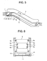
- Fig. 5 is a lateral view showing an escalator according to Embodiment 4 of the present invention.
- Fig. 6 is a sectional view taken along the line VI-VI of Fig. 5 .
- the fixation bracket 10 and the intermediate control portion 11 are disposed below the footsteps 2 on the backward passage side.
- the depth dimension of the main frame 1 is larger than that of Embodiment 1 of the present invention.
- Embodiment 4 of the present invention is identical to Embodiment 1 of the present invention in other constructional details.
- the intermediate control portion 11 is disposed below the footsteps 2 on the backward passage side, so the influences of dust, rain, and the like can further be reduced. Even in the case where other components are disposed between the footsteps 2 on the onward passage side and the footsteps 2 on the backwardpassage side, the intermediate control portion 11 can be disposed at the intermediate inclined portion.
- the intermediate control portion may be disposed below the footsteps on the backward passage side.
- the intermediate control portion may be disposed as a plurality of divided components.
- the inverter, the converter, the reactor, and the regenerative resistor may be constituted by different panels and disposed separately.
- some of the components may be disposed between the footsteps 2 on the onward passage side and the footsteps on the backward passage side, and the remaining components may be disposed below the footsteps on the backward passage side.
- the heat generating components disposed in the intermediate control portion should not be limited to the inverter, the converter, the reactor, and the regenerative resistor.
- the inverter only one or some of the inverter, the converter, the reactor, and the regenerative resistor may be disposed in the intermediate control portion.
- at least the inverter is preferably disposed in the intermediate control portion.
- Components that do not generate heat in particular can also be disposed in the intermediate control portion together with the heat generating components.
- the present invention is also applicable to a moving walkway.
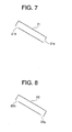
- Each of the intermediate control portions 11, 15a, and 15b illustrated in Embodiments 1 to 4 of the present invention has, for example, one of cases 21 to 24 shown in Figs. 7 to 10 , respectively. That is, the heat generating components such as the inverter and the like are accommodated within each of the cases 21 to 24.
- the case 21 shown in Fig. 7 has an intake port 21a and an exhaust port 21b.
- the intake port 21a is provided to a lower end surface of the case 21 and opens diagonally downward.
- the exhaust port 21b is provided to an upper end portion of a bottom surface of the case 21 and opens downward.
- the intake port 21a is arranged at a position lower than the exhaust port 21b when the case 21 is mounted onto the main frame 1.
- the case 22 shown in Fig. 8 has an intake port 22a and an exhaust port 22b.
- the intake port 22a is provided to a lower end portion of a bottom surface of the case 22 and opens diagonally downward.
- the exhaust port 22b is provided to an upper end portion of the bottom surface of the case 22 and opens diagonally downward.
- the intake port 22a is arranged at a position lower than the exhaust port 22b when the case 22 is mounted onto the main frame 1.
- the case 23 shown in Fig. 9 has an intake port 23a and an exhaust port 23b.
- the intake port 23a is provided to a lower end surface of the case 23 and opens diagonally downward.
- the exhaust port 23b is provided to an upper end surface of the case 23 and opens diagonally upward.
- the intake port 23a is arranged at a position lower than the exhaust port 23b when the case 23 is mounted onto the main frame 1.
- a hood portion 23c for preventing foreign matters (water, dust, and the like) from entering the exhaust port 23b is provided above the exhaust port 23b.
- the case 24 shown in Fig. 10 has an intake port 24a and an exhaust port 24b.
- the intake port 24a is provided to a lower end portion of a bottom surface of the case 24 and opens diagonally downward.
- the exhaust port 24b is provided to an upper end surface of the case 24 and opens diagonally upward.
- the intake port 24a is arranged at a position lower than the exhaust port 24b when the case 24 is mounted onto the main frame 1.
- a hood portion 24c for preventing foreign matters (water, dust, and the like) from entering the exhaust port 24b is provided above the exhaust port 24b.
- the intake ports 21a to 24a are provided at positions lower than the exhaust ports 21b to 24b, respectively, so the air warmed within each of the cases 21 to 24 is swiftly discharged from a corresponding one of the exhaust ports 21b to 24b, and fresh air is hence swiftly taken in from a corresponding one of the intake ports 21a to 24a.
- the heat generating components can be cooled efficiently.
- the cases 23 and 24 are provided with the hood portions 23c and 24c, respectively, so the water and dust that have dropped from gaps among the footsteps 2 can be prevented from entering each of the cases 23 and 24 with a simple construction.
- hood portions may be provided above the intake ports, respectively. Also, hood portions may be provided above both the intake port and the exhaust port, respectively. Further, a plurality of intake ports and a plurality of exhaust ports may be provided. Furthermore, each of the cases may be provided with a fan for forced cooling, fins for discharging heat, or the like.
Landscapes
- Escalators And Moving Walkways (AREA)
Abstract
Description
- The present invention relates to a passenger conveyor having footsteps whose operation speed is controlled by an operation control device including heat a generating component such as an inverter.
- In a conventional escalator, an inverter box and a relay box for performing inverter control of a driving machine are accommodated within an upper machine room (e.g., see Patent Document 1).
- Patent Document 1:
JP 2002-362872 A - In the conventional escalator constructed as described above, the inverter box and the relay box are accommodated within the upper machine room, so the maintenance space within the upper machine room is small. In the case where heat generating components such as an inverter are installed within the upper machine room, heat discharging means and cooling means need to be provided in the upper machine room. However, due to architectural restrictions, it is difficult to secure a space for installing the heat discharging means and the cooling means.
- The present invention has been made to solve the above-mentioned problems, and it is therefore an obj ect of the present invention to provide a passenger conveyor that makes it possible to dispose heat generating components efficiently and secure a maintenance space within a machine room.
- A passenger conveyor according to the present invention includes: a main frame; a plurality of footsteps provided on the main frame and coupled to one another endlessly to be rotated; a footstep driving device for driving the footsteps; and an operation control device for controlling the footstep driving device, in which: the operation control device has an intermediate control portion installed at a lengthwise intermediate portion of the main frame; and the intermediate control portion includes heat generating component that generates heat during operation.
-
-
Fig. 1 is a lateral view showing an escalator according to Embodiment 1 of the present invention. -
Fig. 2 is a sectional view taken along the line II-II ofFig. 1 . -
Fig. 3 is a lateral view showing an escalator according toEmbodiment 2 of the present invention. -
Fig. 4 is a lateral view showing an escalator according to Embodiment 3 of the present invention. -
Fig. 5 is a lateral view showing an escalator according to Embodiment 4 of the present invention. -
Fig. 6 is a sectional view taken along the line VI-VI ofFig. 5 . -
Fig. 7 is a sectional view showing a first example of a case of an intermediate control portion shown in each ofFigs. 1 to 6 . -
Fig. 8 is a sectional view showing a second example of the case of the intermediate control portion shown in each ofFigs. 1 to 6 . -
Fig. 9 is a sectional view showing a third example of the case of the intermediate control portion shown in each ofFigs. 1 to 6 . -
Fig. 10 is a sectional view showing a fourth example of the case of the intermediate control portion shown in each ofFigs. 1 to 6 . - Preferred embodiments of the present invention will be described hereinafter with reference to the drawings.
-
Fig. 1 is a lateral view showing an escalator according to Embodiment 1 of the present invention.Fig. 2 is a sectional view taken along the line II-II ofFig. 1 . Referring toFigs. 1 and 2 , a main frame (truss) 1 is bridged between an upper floor and a lower floor. The main frame 1 has an upper horizontal portion, an intermediate inclined portion, and a lower horizontal portion. The main frame 1 is provided with a plurality offootsteps 2 coupled to one another endlessly. Thefootsteps 2 are rotated within the main frame 1. Each of thefootsteps 2 is provided with a pair ofdriving rollers rollers - A pair of
driving rails driving rollers rails rollers - A
machine room 7 is provided at an upper end portion of the main frame 1 (below a floor located in the vicinity of an upper platform). Afootstep driving device 8 for driving thefootsteps 2 and a main control portion (main control panel) 9 are accommodated within themachine room 7. Thefootstep driving device 8 has a drivingmotor 8a serving as a driving source. - A
fixation bracket 10 is fixed to a lengthwise intermediate portion of the main frame 1, that is, an intermediate portion of the intermediate inclined portion thereof. Thefixation bracket 10 is parallel and horizontal to a width direction of thefootsteps 2. An intermediate control portion (intermediate control panel) 11 is fixed to thefixation bracket 10. The intermediate control portion 11 is disposed between thefootsteps 2 on an onward passage side and thefootsteps 2 on a backward passage side with an inclination in the same direction as an inclination direction of the intermediate inclined portion of the main frame 1. More specifically, the intermediate control portion 11 is inclined parallel to the intermediate inclined portion of the main frame 1. The intermediate control portion 11 includes components for controlling the operation speed of thefootsteps 2, more specifically, an inverter, a converter, a reactor, and a regenerative resistor. - The inverter creates an alternating current corresponding to an arbitrary voltage and an arbitrary frequency from a direct-current voltage produced by the converter, with a view of controlling the
driving motor 8a as an alternating-current motor to generate a required torque efficiently. The inverter creates the alternating current through the switching of the direct-current voltage, and hence generates heat corresponding to a switching loss. - A diode converter or a transistor converter is used as the converter. The diode converter and the transistor converter each create a direct-current voltage from an alternating current of a commercial power supply (with a constant voltage and a frequency of 50 Hz or 60 Hz). The transistor converter has a function of returning regenerative energy to the power supply. In addition, the converter creates the direct-current voltage through the switching of the alternating current, and hence generates heat corresponding to a switching loss.
- The reactor functions as a filter for preventing the outflow of a harmonic and a surge voltage generated through the operations of the inverter and the converter so that the harmonic and the surge voltage do not adversely affect the commercial power supply or the
driving motor 8a. The energy of high-frequency components absorbed by the reactor as the filter is converted into heat, so the reactor generates this heat. - In the case where the driving
motor 8a is turned on by an external force at a speed higher than an intended operation speed, for example, when the escalator is operated downward or stopped with a high on-board ratio, the regenerative resistor converts the energy returned (regenerated) from thedriving motor 8a into heat and consumes this heat. - As described above, the inverter, the converter, the reactor, and the regenerative resistor, which are disposed in the intermediate control portion 11, are all heat generating components that generate heat during operation. Thus, at least one of these heat generating components (e.g., the inverter) is provided with a heat pipe for cooling.
- The operation control device for controlling the
footstep driving device 8 has themain control portion 9 and the intermediate control portion 11. The intermediate control portion 11 is connected to themain control portion 9 via acable 12. Themain control portion 9 is connected to thedriving motor 8a via acable 20. That is, a control signal from the intermediate control portion 11 is input to the drivingmotor 8a via themain control portion 9. However, it is also possible to connect the intermediate control portion 11 to the drivingmotor 8a via a cable so that a control signal from the intermediate control portion 11 is directly input to thedriving motor 8a. - The
main control portion 9 is provided with an interface portion connected communicably to the intermediate control portion 11. The interface portion is provided with an operation portion for inputting changes in the parameters of the inverter and the converter, and a display portion for confirming the states of the inverter and the converter within themachine room 7. Themain control portion 9 has a microcomputer. - In the escalator constructed as described above, the intermediate control portion 11 is installed at the lengthwise intermediate portion of the main frame 1, and the inverter, the converter, the reactor, the regenerative resistor, and the like are disposed in the intermediate control portion 11. Therefore, the heat generating components can be disposed efficiently, and the layout within the
machine room 7 allows an extra space. As a result, a sufficient maintenance space can be secured within themachine room 7. - The heat generated from the heat generating components such as the inverter, the converter, the reactor, the regenerative resistor, and the like can be discharged efficiently from among the
footsteps 2 located above the intermediate control portion 11. The air around the intermediate control portion 11 is stirred due to the movement of thefootsteps 2, so the efficiency in discharging heat from the heat generating components can be enhanced. Also, the temperature within themachine room 7 is restrained from rising. - In addition, the intermediate control portion 11 is disposed with an inclination, so the heat pipe provided in at least one of the heat generating components is also disposed with an inclination. Thus, the surface area of a liquid (e.g., distilled water) within the heat pipe is enlarged in comparison with a case where the intermediate control portion 11 is disposed vertically. Accordingly, a reduction in thermal resistance and an improvement in cooling efficiency are achieved.
- Still further, the intermediate control portion 11 is disposed between the
footsteps 2 on the onward passage side and thefootsteps 2 on the backward passage side, and the intermediate control portion 11 can therefore be exposed simply by removing thefootsteps 2 on the onward passage side, so good maintainability is ensured. Also, the intermediate control portion 11 can be disposed without changing the depth of the main frame 1. - The
main control portion 9 within themachine room 7 is provided with the interface portion, so the states of the components in the intermediate control portion 11 can be confirmed and the settings thereof can be changed without removing thefootsteps 2. - Reference will be made next to
Fig. 3. Fig. 3 is a lateral view showing an escalator according toEmbodiment 2 of the present invention. In this example, a firstfootstep driving device 13a and a secondfootstep driving device 13b for driving thefootsteps 2 are disposed at the intermediate inclined portion. Thefootstep driving devices footsteps 2 on the onward passage side and thefootsteps 2 on the backward passage side. - The intermediate control portion 11 is disposed between the
footstep driving devices main control portion 9 via thecable 12, to the firstfootstep driving device 13a via acable 14a, and to the secondfootstep driving device 13b via acable 14b. That is, the intermediate control portion 11 is directly connected to thefootstep driving devices main control portion 9. Thefootstep driving devices Embodiment 2 of the present invention is identical to Embodiment 1 of the present invention in other constructional details. - With this construction as well, the heat generating components can be disposed efficiently, and a sufficient maintenance space can be secured within the
machine room 7. - Reference will be made next to
Fig. 4. Fig. 4 is a lateral view showing an escalator according to Embodiment 3 of the present invention. Referring toFig.4 ,afirstintermediate controlportion 15a for controlling the firstfootstep driving device 13a, and a secondintermediate control portion 15b for controlling the secondfootstep driving device 13b are disposed at the intermediate inclined portion. The firstintermediate control portion 15a is connected to themain control portion 9 via thecable 12a, and to the firstfootstep driving device 13a via thecable 14a. The secondintermediate control portion 15b is connected to themain control portion 9 via thecable 12b, and to the secondfootstep driving device 13b via thecable 14b. - As described above, the
intermediate control portions footstep driving devices machine room 7. - Reference will be made next to
Fig. 5. Fig. 5 is a lateral view showing an escalator according to Embodiment 4 of the present invention.Fig. 6 is a sectional view taken along the line VI-VI ofFig. 5 . Referring toFigs. 5 and 6 , thefixation bracket 10 and the intermediate control portion 11 are disposed below thefootsteps 2 on the backward passage side. Thus, the depth dimension of the main frame 1 is larger than that of Embodiment 1 of the present invention. Embodiment 4 of the present invention is identical to Embodiment 1 of the present invention in other constructional details. - In the escalator constructed as described above, the intermediate control portion 11 is disposed below the
footsteps 2 on the backward passage side, so the influences of dust, rain, and the like can further be reduced. Even in the case where other components are disposed between thefootsteps 2 on the onward passage side and thefootsteps 2 on the backwardpassage side, the intermediate control portion 11 can be disposed at the intermediate inclined portion. - In the escalator illustrated in each of
Embodiments 2 and 3 of the present invention, the intermediate control portion may be disposed below the footsteps on the backward passage side.
The intermediate control portion may be disposed as a plurality of divided components. For example, the inverter, the converter, the reactor, and the regenerative resistor may be constituted by different panels and disposed separately. In this case, some of the components may be disposed between thefootsteps 2 on the onward passage side and the footsteps on the backward passage side, and the remaining components may be disposed below the footsteps on the backward passage side.
Further, the heat generating components disposed in the intermediate control portion should not be limited to the inverter, the converter, the reactor, and the regenerative resistor.
Still further, only one or some of the inverter, the converter, the reactor, and the regenerative resistor may be disposed in the intermediate control portion. In this case, from the standpoints of the amount of heat generation and the space for installation, at least the inverter is preferably disposed in the intermediate control portion.
Components that do not generate heat in particular can also be disposed in the intermediate control portion together with the heat generating components.
In addition, although the descriptions of the escalator have been given in each of the foregoing examples, the present invention is also applicable to a moving walkway. - Each of the
intermediate control portions cases 21 to 24 shown inFigs. 7 to 10 , respectively. That is, the heat generating components such as the inverter and the like are accommodated within each of thecases 21 to 24. - The
case 21 shown inFig. 7 has an intake port 21a and an exhaust port 21b. The intake port 21a is provided to a lower end surface of thecase 21 and opens diagonally downward. The exhaust port 21b is provided to an upper end portion of a bottom surface of thecase 21 and opens downward. The intake port 21a is arranged at a position lower than the exhaust port 21b when thecase 21 is mounted onto the main frame 1. - The
case 22 shown inFig. 8 has anintake port 22a and anexhaust port 22b. Theintake port 22a is provided to a lower end portion of a bottom surface of thecase 22 and opens diagonally downward. Theexhaust port 22b is provided to an upper end portion of the bottom surface of thecase 22 and opens diagonally downward. Theintake port 22a is arranged at a position lower than theexhaust port 22b when thecase 22 is mounted onto the main frame 1. - The
case 23 shown inFig. 9 has anintake port 23a and anexhaust port 23b. Theintake port 23a is provided to a lower end surface of thecase 23 and opens diagonally downward. Theexhaust port 23b is provided to an upper end surface of thecase 23 and opens diagonally upward. Theintake port 23a is arranged at a position lower than theexhaust port 23b when thecase 23 is mounted onto the main frame 1. In addition, ahood portion 23c for preventing foreign matters (water, dust, and the like) from entering theexhaust port 23b is provided above theexhaust port 23b. - The
case 24 shown inFig. 10 has anintake port 24a and anexhaust port 24b. Theintake port 24a is provided to a lower end portion of a bottom surface of thecase 24 and opens diagonally downward. Theexhaust port 24b is provided to an upper end surface of thecase 24 and opens diagonally upward. Theintake port 24a is arranged at a position lower than theexhaust port 24b when thecase 24 is mounted onto the main frame 1. In addition, ahood portion 24c for preventing foreign matters (water, dust, and the like) from entering theexhaust port 24b is provided above theexhaust port 24b. - In the
cases 21 to 24 constructed as described above, the intake ports 21a to 24a are provided at positions lower than the exhaust ports 21b to 24b, respectively, so the air warmed within each of thecases 21 to 24 is swiftly discharged from a corresponding one of the exhaust ports 21b to 24b, and fresh air is hence swiftly taken in from a corresponding one of the intake ports 21a to 24a. As a result, the heat generating components can be cooled efficiently. - The
cases hood portions footsteps 2 can be prevented from entering each of thecases - The hood portions may be provided above the intake ports, respectively. Also, hood portions may be provided above both the intake port and the exhaust port, respectively.
Further, a plurality of intake ports and a plurality of exhaust ports may be provided.
Furthermore, each of the cases may be provided with a fan for forced cooling, fins for discharging heat, or the like.
Claims (8)
- A passenger conveyor comprising:a main frame;a plurality of footsteps provided on the main frame and coupled to one another endlessly to be rotated;a footstep driving device for driving the footsteps; andan operation control device for controlling the footstep driving device, wherein:the operation control device has an intermediate control portion installed at a lengthwise intermediate portion of the main frame; andthe intermediate control portion includes heat generating component that generates heat during operation.
- A passenger conveyor according to Claim 1, wherein the heat generating component included in the intermediate control portion includes at least one of an inverter, a converter, a reactor, and a regenerative resistor.
- A passenger conveyor according to Claim 1, wherein:the main frame is provided at one lengthwise end thereof with a machine room; andthe operation control device further has an interface portion provided in the machine room and connected communicably to the intermediate control portion.
- A passenger conveyor according to Claim 1, wherein:the main frame has an intermediate inclined portion; andthe intermediate control portion is disposed with an inclination in a same direction as an inclination direction of the intermediate inclined portion.
- A passenger conveyor according to Claim 1, wherein the intermediate control portion is disposed between the footsteps on an onward passage side and the footsteps on a backward passage side.
- A passenger conveyor according to Claim 1, wherein the intermediate control portion is disposed below the footsteps on a backward passage side.
- A passenger conveyor according to Claim 1, wherein:the intermediate control portion has a case for accommodating the heat generating component;the case is provided with an intake port and an exhaust port; andthe intake port is provided at a position lower than the exhaust port.
- A passenger conveyor according to Claim 1, wherein:the intermediate control portion has a case for accommodating the heat generating component;the case is provided with an intake port and an exhaust port; andat least one of the intake port and the exhaust port is provided thereabove with a hood portion for preventing intrusion of foreign matters.
Applications Claiming Priority (1)
| Application Number | Priority Date | Filing Date | Title |
|---|---|---|---|
| PCT/JP2006/313059 WO2008001454A1 (en) | 2006-06-30 | 2006-06-30 | Passenger conveyor |
Publications (2)
| Publication Number | Publication Date |
|---|---|
| EP2036848A1 true EP2036848A1 (en) | 2009-03-18 |
| EP2036848A4 EP2036848A4 (en) | 2013-03-20 |
Family
ID=38845229
Family Applications (1)
| Application Number | Title | Priority Date | Filing Date |
|---|---|---|---|
| EP06767667A Withdrawn EP2036848A4 (en) | 2006-06-30 | 2006-06-30 | PASSENGER TRANSPORT SYSTEM |
Country Status (5)
| Country | Link |
|---|---|
| EP (1) | EP2036848A4 (en) |
| JP (1) | JP5225677B2 (en) |
| KR (1) | KR100980157B1 (en) |
| CN (1) | CN101253118B (en) |
| WO (1) | WO2008001454A1 (en) |
Cited By (2)
| Publication number | Priority date | Publication date | Assignee | Title |
|---|---|---|---|---|
| DE102009034345A1 (en) * | 2009-07-23 | 2011-01-27 | Kone Corp. | Method and device for operating a passenger transport device |
| CN105480829A (en) * | 2014-10-06 | 2016-04-13 | 株式会社日立制作所 | Passenger transportation device |
Families Citing this family (1)
| Publication number | Priority date | Publication date | Assignee | Title |
|---|---|---|---|---|
| JP2016060547A (en) * | 2014-09-12 | 2016-04-25 | 東芝エレベータ株式会社 | Escalator |
Family Cites Families (9)
| Publication number | Priority date | Publication date | Assignee | Title |
|---|---|---|---|---|
| JPS485431Y1 (en) * | 1969-11-17 | 1973-02-10 | ||
| JPS56124667U (en) * | 1980-02-26 | 1981-09-22 | ||
| JPH03147696A (en) * | 1989-11-02 | 1991-06-24 | Hitachi Ltd | Escalator with intermediate horizontal section |
| JP2507670B2 (en) * | 1990-05-30 | 1996-06-12 | 株式会社日立製作所 | Passenger conveyor |
| JPH0895471A (en) * | 1994-09-29 | 1996-04-12 | Tec Corp | Image forming device |
| JP2001302161A (en) * | 2000-04-13 | 2001-10-31 | Hitachi Building Systems Co Ltd | Passenger conveyor control device |
| JP2002362872A (en) * | 2001-06-08 | 2002-12-18 | Hitachi Building Systems Co Ltd | Escalator device |
| JP4031248B2 (en) * | 2002-01-22 | 2008-01-09 | 三菱電機株式会社 | Inclined part high-speed escalator |
| JP3625820B1 (en) * | 2003-08-20 | 2005-03-02 | 株式会社東芝 | Washing machine |
-
2006
- 2006-06-30 EP EP06767667A patent/EP2036848A4/en not_active Withdrawn
- 2006-06-30 JP JP2007521733A patent/JP5225677B2/en not_active Expired - Fee Related
- 2006-06-30 CN CN2006800318018A patent/CN101253118B/en not_active Expired - Fee Related
- 2006-06-30 WO PCT/JP2006/313059 patent/WO2008001454A1/en not_active Ceased
- 2006-06-30 KR KR1020087004598A patent/KR100980157B1/en not_active Expired - Fee Related
Cited By (3)
| Publication number | Priority date | Publication date | Assignee | Title |
|---|---|---|---|---|
| DE102009034345A1 (en) * | 2009-07-23 | 2011-01-27 | Kone Corp. | Method and device for operating a passenger transport device |
| DE102009034345B4 (en) * | 2009-07-23 | 2013-01-03 | Kone Corp. | Method and device for operating a passenger transport device |
| CN105480829A (en) * | 2014-10-06 | 2016-04-13 | 株式会社日立制作所 | Passenger transportation device |
Also Published As
| Publication number | Publication date |
|---|---|
| KR100980157B1 (en) | 2010-09-03 |
| JPWO2008001454A1 (en) | 2009-11-26 |
| WO2008001454A1 (en) | 2008-01-03 |
| CN101253118B (en) | 2011-08-10 |
| EP2036848A4 (en) | 2013-03-20 |
| KR20080046641A (en) | 2008-05-27 |
| CN101253118A (en) | 2008-08-27 |
| JP5225677B2 (en) | 2013-07-03 |
Similar Documents
| Publication | Publication Date | Title |
|---|---|---|
| CN1184126C (en) | Elevator control system | |
| CA2837622C (en) | Elevator shaft termination with a elevator-monitoring arrangement | |
| JP2507670B2 (en) | Passenger conveyor | |
| CN103508294B (en) | Lift facility | |
| EP2036848A1 (en) | Passenger conveyor | |
| JP4597648B2 (en) | Elevator control device | |
| JP4581637B2 (en) | Split device group elevator | |
| EP1467453A2 (en) | Arrangement for the placement of frequency converters | |
| JP5380262B2 (en) | Power converter and elevator control device | |
| CN104024142B (en) | Drives and elevator electronics in the base plate | |
| WO2009075672A1 (en) | Integrated elevator machine motor and drive | |
| JP4782398B2 (en) | Elevator control device | |
| CN112888645B (en) | elevator control panel | |
| JP2013256369A (en) | Passenger conveyor | |
| JPH10291607A (en) | Cargo storage device | |
| CN1968884B (en) | Cooling device for elevator shaft | |
| JPWO2013150617A1 (en) | Elevator equipment | |
| JP2008230813A (en) | Main control board automatic cleaning system for elevator | |
| JP2009113960A (en) | Elevator car control device | |
| JP4873426B2 (en) | Elevator equipment | |
| JP2008297093A (en) | Elevator equipment | |
| JP2016074502A (en) | Passenger conveyor | |
| JP2016060547A (en) | Escalator | |
| JP2005287243A (en) | switchboard | |
| JP2002362872A (en) | Escalator device |
Legal Events
| Date | Code | Title | Description |
|---|---|---|---|
| PUAI | Public reference made under article 153(3) epc to a published international application that has entered the european phase |
Free format text: ORIGINAL CODE: 0009012 |
|
| 17P | Request for examination filed |
Effective date: 20080207 |
|
| AK | Designated contracting states |
Kind code of ref document: A1 Designated state(s): AT BE BG CH CY CZ DE DK EE ES FI FR GB GR HU IE IS IT LI LT LU LV MC NL PL PT RO SE SI SK TR |
|
| AX | Request for extension of the european patent |
Extension state: AL BA HR MK RS |
|
| RBV | Designated contracting states (corrected) |
Designated state(s): DE NL |
|
| DAX | Request for extension of the european patent (deleted) | ||
| A4 | Supplementary search report drawn up and despatched |
Effective date: 20130218 |
|
| RIC1 | Information provided on ipc code assigned before grant |
Ipc: B66B 21/04 20060101ALI20130212BHEP Ipc: B66B 25/00 20060101AFI20130212BHEP |
|
| 17Q | First examination report despatched |
Effective date: 20150901 |
|
| STAA | Information on the status of an ep patent application or granted ep patent |
Free format text: STATUS: THE APPLICATION IS DEEMED TO BE WITHDRAWN |
|
| 18D | Application deemed to be withdrawn |
Effective date: 20160923 |