EP2036650A1 - Joining method and a resultant article - Google Patents
Joining method and a resultant article Download PDFInfo
- Publication number
- EP2036650A1 EP2036650A1 EP08252675A EP08252675A EP2036650A1 EP 2036650 A1 EP2036650 A1 EP 2036650A1 EP 08252675 A EP08252675 A EP 08252675A EP 08252675 A EP08252675 A EP 08252675A EP 2036650 A1 EP2036650 A1 EP 2036650A1
- Authority
- EP
- European Patent Office
- Prior art keywords
- joint
- component part
- component
- sealing
- component parts
- Prior art date
- Legal status (The legal status is an assumption and is not a legal conclusion. Google has not performed a legal analysis and makes no representation as to the accuracy of the status listed.)
- Granted
Links
- 238000000034 method Methods 0.000 title claims abstract description 57
- 238000005304 joining Methods 0.000 title description 7
- 238000007789 sealing Methods 0.000 claims abstract description 23
- 239000011236 particulate material Substances 0.000 claims abstract description 21
- 238000004519 manufacturing process Methods 0.000 claims abstract description 12
- 239000007787 solid Substances 0.000 claims abstract description 11
- 238000009792 diffusion process Methods 0.000 claims abstract description 10
- 230000008595 infiltration Effects 0.000 claims abstract description 8
- 238000001764 infiltration Methods 0.000 claims abstract description 8
- 239000000463 material Substances 0.000 claims description 27
- 239000011888 foil Substances 0.000 claims description 12
- 239000000843 powder Substances 0.000 claims description 10
- 239000011230 binding agent Substances 0.000 claims description 9
- 238000003754 machining Methods 0.000 claims description 9
- 238000005480 shot peening Methods 0.000 claims description 6
- 239000000853 adhesive Substances 0.000 claims description 5
- 230000001070 adhesive effect Effects 0.000 claims description 5
- 239000007789 gas Substances 0.000 description 14
- 230000004888 barrier function Effects 0.000 description 9
- 238000005266 casting Methods 0.000 description 7
- 239000012071 phase Substances 0.000 description 7
- 239000010936 titanium Substances 0.000 description 5
- XKRFYHLGVUSROY-UHFFFAOYSA-N Argon Chemical compound [Ar] XKRFYHLGVUSROY-UHFFFAOYSA-N 0.000 description 4
- VYPSYNLAJGMNEJ-UHFFFAOYSA-N Silicium dioxide Chemical compound O=[Si]=O VYPSYNLAJGMNEJ-UHFFFAOYSA-N 0.000 description 4
- 238000010438 heat treatment Methods 0.000 description 4
- PEDCQBHIVMGVHV-UHFFFAOYSA-N Glycerine Chemical compound OCC(O)CO PEDCQBHIVMGVHV-UHFFFAOYSA-N 0.000 description 3
- RTAQQCXQSZGOHL-UHFFFAOYSA-N Titanium Chemical compound [Ti] RTAQQCXQSZGOHL-UHFFFAOYSA-N 0.000 description 3
- 239000000470 constituent Substances 0.000 description 3
- 238000011109 contamination Methods 0.000 description 3
- 230000000694 effects Effects 0.000 description 3
- 238000002844 melting Methods 0.000 description 3
- 230000008018 melting Effects 0.000 description 3
- 229910052719 titanium Inorganic materials 0.000 description 3
- 239000002699 waste material Substances 0.000 description 3
- 229910001209 Low-carbon steel Inorganic materials 0.000 description 2
- 229910045601 alloy Inorganic materials 0.000 description 2
- 239000000956 alloy Substances 0.000 description 2
- 229910052786 argon Inorganic materials 0.000 description 2
- 239000004568 cement Substances 0.000 description 2
- 239000000919 ceramic Substances 0.000 description 2
- 238000007796 conventional method Methods 0.000 description 2
- 238000013461 design Methods 0.000 description 2
- 239000012768 molten material Substances 0.000 description 2
- 239000002245 particle Substances 0.000 description 2
- 230000002093 peripheral effect Effects 0.000 description 2
- 239000004576 sand Substances 0.000 description 2
- XLYOFNOQVPJJNP-UHFFFAOYSA-N water Substances O XLYOFNOQVPJJNP-UHFFFAOYSA-N 0.000 description 2
- 230000003313 weakening effect Effects 0.000 description 2
- 238000003466 welding Methods 0.000 description 2
- 238000003491 array Methods 0.000 description 1
- 230000009286 beneficial effect Effects 0.000 description 1
- 239000001913 cellulose Substances 0.000 description 1
- 229920002678 cellulose Polymers 0.000 description 1
- 239000002826 coolant Substances 0.000 description 1
- 230000000593 degrading effect Effects 0.000 description 1
- 238000011161 development Methods 0.000 description 1
- 238000009826 distribution Methods 0.000 description 1
- 239000000428 dust Substances 0.000 description 1
- 238000010894 electron beam technology Methods 0.000 description 1
- 238000005242 forging Methods 0.000 description 1
- 239000012535 impurity Substances 0.000 description 1
- 239000007788 liquid Substances 0.000 description 1
- 239000002184 metal Substances 0.000 description 1
- 229910052751 metal Inorganic materials 0.000 description 1
- 239000000203 mixture Substances 0.000 description 1
- 229920000642 polymer Polymers 0.000 description 1
- 230000001141 propulsive effect Effects 0.000 description 1
- 238000005204 segregation Methods 0.000 description 1
- 239000000377 silicon dioxide Substances 0.000 description 1
- 239000007790 solid phase Substances 0.000 description 1
- 239000002904 solvent Substances 0.000 description 1
- 238000003860 storage Methods 0.000 description 1
- 238000012546 transfer Methods 0.000 description 1
Images


Classifications
-
- B—PERFORMING OPERATIONS; TRANSPORTING
- B23—MACHINE TOOLS; METAL-WORKING NOT OTHERWISE PROVIDED FOR
- B23K—SOLDERING OR UNSOLDERING; WELDING; CLADDING OR PLATING BY SOLDERING OR WELDING; CUTTING BY APPLYING HEAT LOCALLY, e.g. FLAME CUTTING; WORKING BY LASER BEAM
- B23K20/00—Non-electric welding by applying impact or other pressure, with or without the application of heat, e.g. cladding or plating
- B23K20/02—Non-electric welding by applying impact or other pressure, with or without the application of heat, e.g. cladding or plating by means of a press ; Diffusion bonding
- B23K20/021—Isostatic pressure welding
-
- B—PERFORMING OPERATIONS; TRANSPORTING
- B23—MACHINE TOOLS; METAL-WORKING NOT OTHERWISE PROVIDED FOR
- B23K—SOLDERING OR UNSOLDERING; WELDING; CLADDING OR PLATING BY SOLDERING OR WELDING; CUTTING BY APPLYING HEAT LOCALLY, e.g. FLAME CUTTING; WORKING BY LASER BEAM
- B23K20/00—Non-electric welding by applying impact or other pressure, with or without the application of heat, e.g. cladding or plating
- B23K20/24—Preliminary treatment
-
- B—PERFORMING OPERATIONS; TRANSPORTING
- B23—MACHINE TOOLS; METAL-WORKING NOT OTHERWISE PROVIDED FOR
- B23K—SOLDERING OR UNSOLDERING; WELDING; CLADDING OR PLATING BY SOLDERING OR WELDING; CUTTING BY APPLYING HEAT LOCALLY, e.g. FLAME CUTTING; WORKING BY LASER BEAM
- B23K2101/00—Articles made by soldering, welding or cutting
- B23K2101/001—Turbines
-
- Y—GENERAL TAGGING OF NEW TECHNOLOGICAL DEVELOPMENTS; GENERAL TAGGING OF CROSS-SECTIONAL TECHNOLOGIES SPANNING OVER SEVERAL SECTIONS OF THE IPC; TECHNICAL SUBJECTS COVERED BY FORMER USPC CROSS-REFERENCE ART COLLECTIONS [XRACs] AND DIGESTS
- Y10—TECHNICAL SUBJECTS COVERED BY FORMER USPC
- Y10T—TECHNICAL SUBJECTS COVERED BY FORMER US CLASSIFICATION
- Y10T29/00—Metal working
- Y10T29/49—Method of mechanical manufacture
- Y10T29/49316—Impeller making
- Y10T29/49318—Repairing or disassembling
-
- Y—GENERAL TAGGING OF NEW TECHNOLOGICAL DEVELOPMENTS; GENERAL TAGGING OF CROSS-SECTIONAL TECHNOLOGIES SPANNING OVER SEVERAL SECTIONS OF THE IPC; TECHNICAL SUBJECTS COVERED BY FORMER USPC CROSS-REFERENCE ART COLLECTIONS [XRACs] AND DIGESTS
- Y10—TECHNICAL SUBJECTS COVERED BY FORMER USPC
- Y10T—TECHNICAL SUBJECTS COVERED BY FORMER US CLASSIFICATION
- Y10T29/00—Metal working
- Y10T29/49—Method of mechanical manufacture
- Y10T29/49718—Repairing
- Y10T29/49719—Seal or element thereof
-
- Y—GENERAL TAGGING OF NEW TECHNOLOGICAL DEVELOPMENTS; GENERAL TAGGING OF CROSS-SECTIONAL TECHNOLOGIES SPANNING OVER SEVERAL SECTIONS OF THE IPC; TECHNICAL SUBJECTS COVERED BY FORMER USPC CROSS-REFERENCE ART COLLECTIONS [XRACs] AND DIGESTS
- Y10—TECHNICAL SUBJECTS COVERED BY FORMER USPC
- Y10T—TECHNICAL SUBJECTS COVERED BY FORMER US CLASSIFICATION
- Y10T29/00—Metal working
- Y10T29/49—Method of mechanical manufacture
- Y10T29/49718—Repairing
- Y10T29/49721—Repairing with disassembling
- Y10T29/49723—Repairing with disassembling including reconditioning of part
- Y10T29/49725—Repairing with disassembling including reconditioning of part by shaping
- Y10T29/49726—Removing material
- Y10T29/49728—Removing material and by a metallurgical operation, e.g., welding, diffusion bonding, casting
Definitions
- the present invention relates to a joining method and an article formed thereby and is more particularly related to manufacturing an article by joining component parts by diffusion bonding. It finds particular application in joining components to form components of a gas turbine engine in which the joints must be of high integrity. However, it is also applicable to diverse other applications.
- Such components may be components for a gas turbine engine, such as an integrally bladed disc (known as a blisk) for a compressor or turbine stage.
- a gas turbine engine such as an integrally bladed disc (known as a blisk) for a compressor or turbine stage.
- Such components are machined from wrought material. Whilst machining from a wrought material block provides a component with good mechanical properties, it can result in large amounts of material being machined away as waste. Furthermore, to produce complex shapes, particularly having tight tolerances, may require considerable machining time and / or complex tooling to achieve the desired profiles.
- An alternative conventional method of producing such articles or components is by casting, which produces less waste material than machining from wrought.
- Complex components may require additional protrusions to assist in supporting the component and controlling material distribution during the casting process. Therefore, cast components may require subsequent machining to remove these additional protrusions. Nevertheless there is less material wastage, and hence expense, in casting complex components than in machining from wrought.
- one problem with this method is that casting is a relatively lengthy process since a sacrificial mould must be formed, the molten material poured into the mould, the mould and molten material slowly cooled and then the mould removed.
- Another problem with casting is that the mechanical properties of a cast component are relatively poor due to porosity caused by entrapped gases and shrinkage, inhomogeneous structure, inclusions and segregation within the component.
- the component is also prone to significant shrinkage due to the large thermal expansion coefficient during the liquid to solid phase change. In most cases this leads to a requirement for the casting to be larger than the desired end component size.
- the poor mechanical properties may make castings unsuitable for some applications, especially those in fatigue situations, or lead to a high scrap rate in production due to the high product integrity required.
- a still further conventional method of joining components is by electron beam welding as shown in US 5,390,413 .
- this is an effective joining method
- a problem with it is the microstructural changes and phase changes caused in and around the weld area by the heat effects. This can weaken the bond between component parts, stress the component parts and / or change the properties of the resultant article.
- Other problems are the relatively large amount of post-weld machining required to achieve the desired shape, the component design limitations imposed by the heavy tooling and required welding motion, and the high levels of capital investment and development work required to produce new components.
- the present invention seeks to provide a method of manufacturing an article by joining component parts, and an article formed thereby, that seeks to address the aforementioned problems.
- the present invention provides a method of manufacturing an article by diffusion bonding, the method comprising the steps of assembling first and second component parts having a joint therebetween; sealing the joint against infiltration by solid particulate material, without causing phase change of the component parts; and applying heat and isostatic pressure via a solid particulate material to form a consolidated joint by diffusion bonding.
- the method further comprises the step of machining the consolidated joint to provide the required surface finish.
- the step of assembling the component parts comprises forming a slot in the first component part and inserting at least a part of the second component part into the slot in the first component part to form an interference fit joint.
- the step of sealing the joint comprises smearing material from one or both of the component parts across the joint.
- the smearing is performed by burnishing the joint with a burnishing tool.
- the step of sealing the joint comprises shot peening the joint.
- the material used in the shot peening is the same material as that used in the component parts.
- the step of sealing the joint comprises securing a thin foil sheet across the joint.
- the thin foil sheet comprises mild steel.
- the thin foil sheet is bound to the joint by adhesive. More preferably the adhesive is a ceramic cement.
- the step of sealing the joint comprises applying a powder in a binder across the joint.
- the powder is the same material as the component parts. More preferably the powder comprises particles with a diameter of less than 20 microns.
- the binder comprises a water-based binder.
- the first component part is a disc and the second component part is a blade.
- a second aspect of the present invention provides a method according to any of the previous eight paragraphs wherein the method further comprises, between the assembling and sealing steps, the step of assembling at least one further component part, the or each further component part having a further joint with the first component part and / or the second component part.
- a third aspect of the present invention provides a method according to the same eight paragraphs wherein the method further comprises, between the sealing and applying heat and isostatic pressure steps, the steps of assembling at least one further component part, the or each further component part having a further joint with the first component part and / or the second component part and sealing the further joint against infiltration by solid particulate material, without causing phase change of the component parts.
- a final aspect of the present invention provides a gas turbine engine comprising an article manufactured by the method described above.
- a gas turbine engine 10 is shown in Figure 1 and comprises an air intake 12 and a propulsive fan 14 that generates two airflows A and B.
- the gas turbine engine 10 comprises, in axial flow A, an intermediate pressure compressor 16, a high pressure compressor 18, a combustor 20, a high pressure turbine 22, an intermediate pressure turbine 24, a low pressure turbine 26 and an exhaust nozzle 28.
- a nacelle 30 surrounds the gas turbine engine 10 and defines, in axial flow B, a bypass duct 32.
- the fan 14, compressors 16, 18 and turbines 22, 24, 26 may all be formed as integrally bladed discs, or blisks 34.
- a typical blisk 34 is shown in Figure 2 and comprises a disc 36 integrally formed with one or more arrays of blades 38 on its peripheral surface. Typically the disc 36 and blades 38 are formed separately and then joined together to form the blisk 34.
- the method of the present invention finds particular utility in forming blisks from a disc and a plurality of blades.
- a disc 36 has a slot 40 formed in its peripheral surface.
- a blade 38 with a widened root portion 42 is pushed into the slot 40 to form an interference fit.
- a joint 44 is formed between the disc 36 and the root portion 42 of the blade 38.
- Particulate material that may contaminate the joint includes the particulate material used to transfer heat and isostatic pressure but can also include dust or other foreign matter that may accumulate on the assembly or the constituent parts 36, 38 during storage prior to assembly or between assembly and the application of heat and pressure.
- the disc 36 is typically machined from a wrought block of titanium 6/4 and the blades 38 are typically forged from titanium 6/4.
- other materials suitable to the application may be contemplated without departing from the scope of the invention herein described.
- the second step of the method of the present invention is concerned with sealing the joint 44 against infiltration by particulate material.
- Figures 4 - 7 are enlargements of the joint area, marked as J on Figure 3 , showing respectively four embodiments of the sealing step of the method of the present invention. Each shows part of the disc 36, the root portion 42 of the blade 38 and the joint 44 therebetween.
- Figure 4 shows a step of smearing material from the root portion 42 of the blade 38 across the joint 44 and onto the disc 36.
- This forms an impenetrable barrier layer 46 across the joint 44 without significantly disrupting the profile of either the root portion 42 of the blade 38 or the disc 36.
- the barrier layer 46 is formed by burnishing.
- a burnishing tool 48 is brought into contact with the surface of the component to be smeared and rotated, either clockwise or anticlockwise, as shown by arrow 50. This disrupts the material on the surface of the component and spreads it to form the barrier layer 46, which is impermeable to particulate material but may not be impermeable to gases.
- the material may be smeared from the disc 36 across the joint 44 and onto the root portion 42 of the blade 38 to form the barrier layer 46. It will generally be a matter of convenience or design which component the material is smeared from.
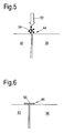
- FIG. 5 shows a second embodiment of a sealing step of the method of the present invention.
- a shot peening source 52 is located above and traverses along the joint 44.
- the source 52 discharges shots 54 towards the joint 44.
- the shots 54 are the same material as the disc 36 and / or the root portion 42 of the blade 38 to prevent contamination of the joint 44, for example titanium 6/4.
- the shots 54 may be a different material.
- the impact of the shots 54 on the joint 44 locally plastically deforms the surface of the components 42, 36 around the joint 44 to compress the joint 44 and thereby close its edges together. This forms a barrier at the joint 44 that is impermeable to particulate material, but not necessary to gases.
- no heating or melting of the root portion 42 of the blade 38 or the disc 36 is caused by shot peening and hence there is no phase change or microstructural changes.
- Figure 6 shows a third embodiment of a sealing step of the method of the present invention.
- a thin foil sheet 56 is placed over the joint 44 so that it overlaps onto both the disc 36 and the root portion 42 of the blade 38.
- the thin foil sheet 56 is preferably secured to the components 42, 36 to improve the impermeability of the barrier thereformed and to allow the blisk 34 to be rotated, for example to enable other blades 38 to be inserted into slots 40 in the disc 36 prior to the application of heat and isostatic pressure.
- Any known method of securing the thin foil sheet 56 to the components 42, 36 may be used as known in the art, none of which require the blade 38 or the disc 36 to be heated or melted or to undergo phase changes.
- the foil sheet 56 may be wrapped around the joint 44.
- the foil sheet 56 may be secured using adhesive, particularly a ceramic cement.
- the foil sheet 56 may comprises a mild steel. Alternatively, it may comprise the same material as the root portion 42 of the blade 38 and / or the disc 36, particularly Ti 6/4 to avoid contamination of the joint 44.
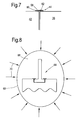
- a fourth embodiment of the sealing step of the method of the present invention is shown in Figure 7 .
- a paste 58 comprising powder 60 in a binder 62 is applied across the joint 44 to form a barrier layer that is impenetrable to particulate material, but not necessarily to gases.
- the paste 58 is applied without heating or melting and therefore does not cause phase changes or microstructural changes.
- the powder 60 comprises the same material as the disc 36 and root portion 42 of the blade 38, being a metal, particularly Ti 6/4. This prevents contamination of the joint 44.
- the powder 60 may comprise a different material.
- the powder particles 60 have a diameter of less than 20 microns.
- the paste 58 typically comprises mainly powder 60 with a few percentage of the total volume comprising the binder 62.
- the binder 62 may be any suitable composition as is known in the art.
- a typical aqueous binder 62 comprises 200g water, 0.5g glycerol and 1.5g cellulose.
- other aqueous, solvent or polymer based binders may be used as is well known in the art.
- This forms a paste 58 that is sufficiently adhesive to adhere to the components 42, 36 and that forms a smooth barrier layer to prevent infiltration of the joint 44 by particulate material during the step of applying heat and isostatic pressure.
- the sealed assembly 64 comprising the disc 36 and blade or blades 38, with the joints 44 sealed by any of the embodiments described above is prepared for the application of heat and isostatic pressure.
- the sealed assembly 64 is surrounded by solid particulate material 66, typically silica sand or an alternative inert sand.
- solid particulate material 66 typically silica sand or an alternative inert sand.
- a pliant chamber 68 Surrounding and enclosing the sealed assembly 64 and the particulate material 66 is a pliant chamber 68, which can deform under applied pressure and is gas impermeable. A vacuum is then created within the pliant chamber 68.
- the final step of the method of the present invention involves applying heat and isostatic pressure 70 to the pliant chamber 68.
- the isostatic pressure 70 typically supplied by pressurising argon against the pliant chamber 68, deforms the wall of the pliant chamber 68 inwardly towards the sealed assembly 64 whilst both the heat and isostatic pressure 70 are transmitted through the solid particulate material 66 to the sealed assembly 64.
- This has the effect of diffusion bonding the component parts of the sealed assembly 64 together to form a blisk 34 as shown in Figure 2 .
- the barrier formed across the joint 44 by any of the embodiments of the sealing step prevents any of the solid particulate material 66 entering the joint 44 and thereby weakening it or altering the mechanical properties of it.
- the blisk 34 may be machined to provide the desired surface profile of the blisk 34 and to remove any minor surface impurities, for example from the thin foil sheet 56.
- the method of the present invention provides a fully consolidated, diffusion bonded component, blisk 34, with substantially the same material properties as the constituent component parts, disc 36 and blades 38, produced by machining from a wrought block or forging.
- the method of the present invention has been described with respect to manufacturing a blisk, it is equally applicable to the manufacture of other components within a gas turbine engine including, but not limited to, outlet guide vanes and centrifugal compressors. Similarly, the method can be used to manufacture articles and components by diffusion bonding in other industries in which there is a requirement to form components from constituent parts without degrading the mechanical properties in or near the joint.
- Different materials or alloys may be utilised with equal felicity in the method of the present invention.
- Two component parts formed of different materials or alloys may be joined by the method of the present invention to form a graded functionality component.
- isostatic pressure source has been described as argon, any suitable alternative as known in the art may be substituted to derive the benefits of the present invention.
- the article produced is cheaper and easier to manufacture by the method of the present invention than by prior art methods.
- the sealing performed has a less stringent sealing requirement, since it need withstand only particulate material and not gas infiltration.
Landscapes
- Engineering & Computer Science (AREA)
- Mechanical Engineering (AREA)
- Pressure Welding/Diffusion-Bonding (AREA)
- Powder Metallurgy (AREA)
Abstract
Description
- The present invention relates to a joining method and an article formed thereby and is more particularly related to manufacturing an article by joining component parts by diffusion bonding. It finds particular application in joining components to form components of a gas turbine engine in which the joints must be of high integrity. However, it is also applicable to diverse other applications.
- There are many industries in which it is necessary to produce relatively complex components having good mechanical properties but that are relatively cheap, produce little waste material and have a low scrap rate in production. Such components may be components for a gas turbine engine, such as an integrally bladed disc (known as a blisk) for a compressor or turbine stage.
- Typically such components are machined from wrought material. Whilst machining from a wrought material block provides a component with good mechanical properties, it can result in large amounts of material being machined away as waste. Furthermore, to produce complex shapes, particularly having tight tolerances, may require considerable machining time and / or complex tooling to achieve the desired profiles.
- An alternative conventional method of producing such articles or components is by casting, which produces less waste material than machining from wrought. Complex components may require additional protrusions to assist in supporting the component and controlling material distribution during the casting process. Therefore, cast components may require subsequent machining to remove these additional protrusions. Nevertheless there is less material wastage, and hence expense, in casting complex components than in machining from wrought. However, one problem with this method is that casting is a relatively lengthy process since a sacrificial mould must be formed, the molten material poured into the mould, the mould and molten material slowly cooled and then the mould removed.
- Another problem with casting is that the mechanical properties of a cast component are relatively poor due to porosity caused by entrapped gases and shrinkage, inhomogeneous structure, inclusions and segregation within the component. The component is also prone to significant shrinkage due to the large thermal expansion coefficient during the liquid to solid phase change. In most cases this leads to a requirement for the casting to be larger than the desired end component size. The poor mechanical properties may make castings unsuitable for some applications, especially those in fatigue situations, or lead to a high scrap rate in production due to the high product integrity required.
- A still further conventional method of joining components is by electron beam welding as shown in
US 5,390,413 . Although this is an effective joining method, a problem with it is the microstructural changes and phase changes caused in and around the weld area by the heat effects. This can weaken the bond between component parts, stress the component parts and / or change the properties of the resultant article. Other problems are the relatively large amount of post-weld machining required to achieve the desired shape, the component design limitations imposed by the heavy tooling and required welding motion, and the high levels of capital investment and development work required to produce new components. - The present invention seeks to provide a method of manufacturing an article by joining component parts, and an article formed thereby, that seeks to address the aforementioned problems.
- Accordingly the present invention provides a method of manufacturing an article by diffusion bonding, the method comprising the steps of assembling first and second component parts having a joint therebetween; sealing the joint against infiltration by solid particulate material, without causing phase change of the component parts; and applying heat and isostatic pressure via a solid particulate material to form a consolidated joint by diffusion bonding.
- Preferably the method further comprises the step of machining the consolidated joint to provide the required surface finish.
- Preferably the step of assembling the component parts comprises forming a slot in the first component part and inserting at least a part of the second component part into the slot in the first component part to form an interference fit joint.
- Preferably the step of sealing the joint comprises smearing material from one or both of the component parts across the joint. Preferably the smearing is performed by burnishing the joint with a burnishing tool.
- Alternatively the step of sealing the joint comprises shot peening the joint. Preferably the material used in the shot peening is the same material as that used in the component parts.
- Alternatively the step of sealing the joint comprises securing a thin foil sheet across the joint. Preferably the thin foil sheet comprises mild steel. Preferably the thin foil sheet is bound to the joint by adhesive. More preferably the adhesive is a ceramic cement.
- Alternatively the step of sealing the joint comprises applying a powder in a binder across the joint. Preferably the powder is the same material as the component parts. More preferably the powder comprises particles with a diameter of less than 20 microns. Preferably the binder comprises a water-based binder.
- Preferably the first component part is a disc and the second component part is a blade.
- A second aspect of the present invention provides a method according to any of the previous eight paragraphs wherein the method further comprises, between the assembling and sealing steps, the step of assembling at least one further component part, the or each further component part having a further joint with the first component part and / or the second component part.
- A third aspect of the present invention provides a method according to the same eight paragraphs wherein the method further comprises, between the sealing and applying heat and isostatic pressure steps, the steps of assembling at least one further component part, the or each further component part having a further joint with the first component part and / or the second component part and sealing the further joint against infiltration by solid particulate material, without causing phase change of the component parts.
- A final aspect of the present invention provides a gas turbine engine comprising an article manufactured by the method described above.
- The present invention will be more fully described by way of example with reference to the accompanying drawings, in which:
-
Figure 1 is a sectional side view of a gas turbine engine. -
Figure 2 is a perspective view of a blisk manufactured according to the method of the present invention. -
Figure 3 is a schematic side view of a blisk assembly at the first step in the method of the present invention. -
Figure 4 is an enlargement of the joint showing a first embodiment of the second step of the method of the present invention. -
Figure 5 is an enlargement of the joint showing a second embodiment of the second step of the method of the present invention. -
Figure 6 is an enlargement of the joint showing a third embodiment of the second step of the method of the present invention. -
Figure 7 is an enlargement of the joint showing a fourth embodiment of the second step of the method of the present invention. -
Figure 8 is a schematic side view of a blisk assembly at the final step in the method of the present invention. - A
gas turbine engine 10 is shown inFigure 1 and comprises anair intake 12 and apropulsive fan 14 that generates two airflows A and B. Thegas turbine engine 10 comprises, in axial flow A, anintermediate pressure compressor 16, ahigh pressure compressor 18, acombustor 20, ahigh pressure turbine 22, anintermediate pressure turbine 24, alow pressure turbine 26 and anexhaust nozzle 28. Anacelle 30 surrounds thegas turbine engine 10 and defines, in axial flow B, abypass duct 32. - The
fan 14,compressors turbines blisks 34. Atypical blisk 34 is shown inFigure 2 and comprises adisc 36 integrally formed with one or more arrays ofblades 38 on its peripheral surface. Typically thedisc 36 andblades 38 are formed separately and then joined together to form theblisk 34. The method of the present invention finds particular utility in forming blisks from a disc and a plurality of blades. - The method of the present invention will now be described with reference to the assembly shown in
Figure 3 . In the first step of the manufacturing method of the present invention adisc 36 has aslot 40 formed in its peripheral surface. Ablade 38 with a widenedroot portion 42 is pushed into theslot 40 to form an interference fit. Ajoint 44 is formed between thedisc 36 and theroot portion 42 of theblade 38. Although thejoint 44 is formed as an interference fit, this is not a sufficiently tight joint to prevent particulate material from entering the joint, and thereby weakening it, during the application of heat and isostatic pressure which constitutes the final step of the method. Particulate material that may contaminate the joint includes the particulate material used to transfer heat and isostatic pressure but can also include dust or other foreign matter that may accumulate on the assembly or theconstituent parts - The
disc 36 is typically machined from a wrought block of titanium 6/4 and theblades 38 are typically forged from titanium 6/4. However, other materials suitable to the application may be contemplated without departing from the scope of the invention herein described. - The second step of the method of the present invention is concerned with sealing the joint 44 against infiltration by particulate material.
Figures 4 - 7 are enlargements of the joint area, marked as J onFigure 3 , showing respectively four embodiments of the sealing step of the method of the present invention. Each shows part of thedisc 36, theroot portion 42 of theblade 38 and the joint 44 therebetween. -
Figure 4 shows a step of smearing material from theroot portion 42 of theblade 38 across the joint 44 and onto thedisc 36. This forms animpenetrable barrier layer 46 across the joint 44 without significantly disrupting the profile of either theroot portion 42 of theblade 38 or thedisc 36. Thebarrier layer 46 is formed by burnishing. In the figure, aburnishing tool 48 is brought into contact with the surface of the component to be smeared and rotated, either clockwise or anticlockwise, as shown byarrow 50. This disrupts the material on the surface of the component and spreads it to form thebarrier layer 46, which is impermeable to particulate material but may not be impermeable to gases. There is no requirement to heat the component during burnishing, either generally or in the vicinity of the joint 44. The process of burnishing the joint 44, or smearing material across it, does not cause heating or melting of either theroot portion 42 of theblade 38 or thedisc 36. This is beneficial because it prevents the microstructural changes and phase changes that are produced around areas of significant heating, for example in and around welded joints. It also removes the need for additional heat sinks or coolant application to try to counteract these effects. - Alternatively the material may be smeared from the
disc 36 across the joint 44 and onto theroot portion 42 of theblade 38 to form thebarrier layer 46. It will generally be a matter of convenience or design which component the material is smeared from. -
Figure 5 shows a second embodiment of a sealing step of the method of the present invention. Ashot peening source 52 is located above and traverses along the joint 44. Thesource 52discharges shots 54 towards the joint 44. Preferably theshots 54 are the same material as thedisc 36 and / or theroot portion 42 of theblade 38 to prevent contamination of the joint 44, for example titanium 6/4. Alternatively, theshots 54 may be a different material. The impact of theshots 54 on the joint 44 locally plastically deforms the surface of thecomponents root portion 42 of theblade 38 or thedisc 36 is caused by shot peening and hence there is no phase change or microstructural changes. -
Figure 6 shows a third embodiment of a sealing step of the method of the present invention. Athin foil sheet 56 is placed over the joint 44 so that it overlaps onto both thedisc 36 and theroot portion 42 of theblade 38. Thethin foil sheet 56 is preferably secured to thecomponents blisk 34 to be rotated, for example to enableother blades 38 to be inserted intoslots 40 in thedisc 36 prior to the application of heat and isostatic pressure. Any known method of securing thethin foil sheet 56 to thecomponents blade 38 or thedisc 36 to be heated or melted or to undergo phase changes. Typically thefoil sheet 56 may be wrapped around the joint 44. Alternatively, thefoil sheet 56 may be secured using adhesive, particularly a ceramic cement. - The
foil sheet 56 may comprises a mild steel. Alternatively, it may comprise the same material as theroot portion 42 of theblade 38 and / or thedisc 36, particularly Ti 6/4 to avoid contamination of the joint 44. - A fourth embodiment of the sealing step of the method of the present invention is shown in
Figure 7 . Apaste 58 comprisingpowder 60 in abinder 62 is applied across the joint 44 to form a barrier layer that is impenetrable to particulate material, but not necessarily to gases. Thepaste 58 is applied without heating or melting and therefore does not cause phase changes or microstructural changes. Preferably thepowder 60 comprises the same material as thedisc 36 androot portion 42 of theblade 38, being a metal, particularly Ti 6/4. This prevents contamination of the joint 44. Alternatively thepowder 60 may comprise a different material. Typically thepowder particles 60 have a diameter of less than 20 microns. Thepaste 58 typically comprises mainlypowder 60 with a few percentage of the total volume comprising thebinder 62. - The
binder 62 may be any suitable composition as is known in the art. A typicalaqueous binder 62 comprises 200g water, 0.5g glycerol and 1.5g cellulose. However, other aqueous, solvent or polymer based binders may be used as is well known in the art. This forms apaste 58 that is sufficiently adhesive to adhere to thecomponents - The final step in the method of the present invention is shown in
Figure 8 . The sealedassembly 64, comprising thedisc 36 and blade orblades 38, with thejoints 44 sealed by any of the embodiments described above is prepared for the application of heat and isostatic pressure. The sealedassembly 64 is surrounded by solidparticulate material 66, typically silica sand or an alternative inert sand. Surrounding and enclosing the sealedassembly 64 and theparticulate material 66 is apliant chamber 68, which can deform under applied pressure and is gas impermeable. A vacuum is then created within thepliant chamber 68. - The final step of the method of the present invention involves applying heat and
isostatic pressure 70 to thepliant chamber 68. Theisostatic pressure 70, typically supplied by pressurising argon against thepliant chamber 68, deforms the wall of thepliant chamber 68 inwardly towards the sealedassembly 64 whilst both the heat andisostatic pressure 70 are transmitted through the solidparticulate material 66 to the sealedassembly 64. This has the effect of diffusion bonding the component parts of the sealedassembly 64 together to form ablisk 34 as shown inFigure 2 . The barrier formed across the joint 44 by any of the embodiments of the sealing step prevents any of the solidparticulate material 66 entering the joint 44 and thereby weakening it or altering the mechanical properties of it. - Subsequent to the application of heat and isostatic pressure the
blisk 34, particularly around where the joint 44 was, may be machined to provide the desired surface profile of theblisk 34 and to remove any minor surface impurities, for example from thethin foil sheet 56. - The method of the present invention provides a fully consolidated, diffusion bonded component,
blisk 34, with substantially the same material properties as the constituent component parts,disc 36 andblades 38, produced by machining from a wrought block or forging. - Although the method of the present invention has been described with respect to manufacturing a blisk, it is equally applicable to the manufacture of other components within a gas turbine engine including, but not limited to, outlet guide vanes and centrifugal compressors. Similarly, the method can be used to manufacture articles and components by diffusion bonding in other industries in which there is a requirement to form components from constituent parts without degrading the mechanical properties in or near the joint.
- Different materials or alloys may be utilised with equal felicity in the method of the present invention. Two component parts formed of different materials or alloys may be joined by the method of the present invention to form a graded functionality component.
- Although the isostatic pressure source has been described as argon, any suitable alternative as known in the art may be substituted to derive the benefits of the present invention.
- It will be appreciated that the article produced is cheaper and easier to manufacture by the method of the present invention than by prior art methods. The sealing performed has a less stringent sealing requirement, since it need withstand only particulate material and not gas infiltration.
Claims (15)
- A method of manufacturing an article (34) by diffusion bonding, the method comprising the steps ofa) assembling first (36) and second (38) component parts having a joint (44) therebetween;b) sealing the joint (44) against infiltration by solid particulate material, without causing phase change of the component parts; andc) applying heat and isostatic pressure (70) via a solid particulate material (66) to form a consolidated joint by diffusion bonding.
- A method as claimed in claim 1 wherein the method further comprises the step of machining the consolidated joint to provide the required surface finish.
- A method as claimed in claim 1 wherein the step of assembling the component parts (36, 38) comprises forming a slot (40) in the first component part (36) and inserting at least a part (42) of the second component part (38) into the slot (40) in the first component part (36) to form an interference fit joint (44).
- A method as claimed in any of claims 1 to 3 wherein the step of sealing the joint (44) comprises smearing material from one or both of the component parts (36, 38) across the joint (44).
- A method as claimed in claim 4 wherein the smearing is performed by burnishing the joint (44) with a burnishing tool (48).
- A method as claimed in any of claims 1 to 3 wherein the step of sealing the joint (44) comprises shot peening the joint (44).
- A method as claimed in claim 6 wherein the material used in the shot peening is the same material as that used in the component parts (36, 38).
- A method as claimed in any of claims 1 to 3 wherein the step of sealing the joint (44) comprises securing a thin foil sheet (56) across the joint (44).
- A method as claimed in claim 8 wherein the thin foil sheet (56) is bound to the joint (44) by adhesive.
- A method as claimed in any of claims 1 to 3 wherein the step of sealing the joint (44) comprises applying a powder (60) in a binder (62) across the joint (44).
- A method as claimed in claim 10 wherein the powder (60) is the same material as the component parts (36, 38).
- A method as claimed in any preceding claim wherein the first component part (36) is a disc and the second component part (38) is a blade.
- A method as claimed in any preceding claim wherein the method further comprises, between steps 1a) and 1b), the step of assembling at least one further component part, the or each further component part having a further joint with the first component part and / or the second component part.
- A method as claimed in any of claims 1 to 14 wherein the method further comprises, between steps 1b) and 1c), the steps of assembling at least one further component part, the or each further component part having a further joint with the first component part and / or the second component part; and sealing the further joint against infiltration by solid particulate material, without causing phase change of the component parts.
- A gas turbine engine (10) comprising an article (34) manufactured by the method of any preceding claim.
Applications Claiming Priority (1)
| Application Number | Priority Date | Filing Date | Title |
|---|---|---|---|
| GBGB0718026.8A GB0718026D0 (en) | 2007-09-15 | 2007-09-15 | Joining method and a resultant article |
Publications (2)
| Publication Number | Publication Date |
|---|---|
| EP2036650A1 true EP2036650A1 (en) | 2009-03-18 |
| EP2036650B1 EP2036650B1 (en) | 2016-03-23 |
Family
ID=38659023
Family Applications (1)
| Application Number | Title | Priority Date | Filing Date |
|---|---|---|---|
| EP08252675.7A Ceased EP2036650B1 (en) | 2007-09-15 | 2008-08-12 | Joining method |
Country Status (3)
| Country | Link |
|---|---|
| US (1) | US8322595B2 (en) |
| EP (1) | EP2036650B1 (en) |
| GB (1) | GB0718026D0 (en) |
Cited By (2)
| Publication number | Priority date | Publication date | Assignee | Title |
|---|---|---|---|---|
| EP2540963A3 (en) * | 2011-06-30 | 2017-07-26 | General Electric Company | Turbine disk preform, welded turbine rotor made therewith and methods of making the same |
| EP3597348A1 (en) * | 2018-07-18 | 2020-01-22 | Rolls-Royce plc | A method of diffusion bonding |
Families Citing this family (2)
| Publication number | Priority date | Publication date | Assignee | Title |
|---|---|---|---|---|
| US8727203B2 (en) | 2010-09-16 | 2014-05-20 | Howmedica Osteonics Corp. | Methods for manufacturing porous orthopaedic implants |
| GB201522522D0 (en) * | 2015-12-21 | 2016-02-03 | Rolls Royce Plc | A fan blade root block assembly |
Citations (5)
| Publication number | Priority date | Publication date | Assignee | Title |
|---|---|---|---|---|
| GB2109274A (en) * | 1981-11-13 | 1983-06-02 | Rolls Royce | Gas turbine engine rotor assembly |
| US4485961A (en) * | 1982-03-29 | 1984-12-04 | Asea Aktiebolag | Welding by hot isostatic pressing (HIP) |
| US4529452A (en) * | 1984-07-30 | 1985-07-16 | United Technologies Corporation | Process for fabricating multi-alloy components |
| WO2005123310A1 (en) * | 2004-06-18 | 2005-12-29 | Metso Powdermet Oy | Method for manufacturing composite material with hot isostatic pressing, and a composite material |
| US20060086776A1 (en) | 2004-10-22 | 2006-04-27 | Gandy David W | Method to join or repair superalloy hot section turbine components using hot isostatic processing |
Family Cites Families (10)
| Publication number | Priority date | Publication date | Assignee | Title |
|---|---|---|---|---|
| US3483610A (en) * | 1967-06-08 | 1969-12-16 | Bell Telephone Labor Inc | Thermocompression bonding of foil leads |
| CA1042641A (en) * | 1975-12-24 | 1978-11-21 | Westinghouse Canada Limited | Manufacture of composites for turbine blades |
| US4241135A (en) * | 1979-02-09 | 1980-12-23 | General Electric Company | Polycrystalline diamond body/silicon carbide substrate composite |
| CA1156562A (en) | 1980-06-23 | 1983-11-08 | George S. Hoppin, Iii | Dual alloy turbine wheels |
| DE3607699A1 (en) * | 1986-03-08 | 1987-09-10 | Messerschmitt Boelkow Blohm | METHOD FOR DIFFUSION WELDING WITH ISOSTATIC PRESSURE |
| GB2271524B (en) * | 1992-10-16 | 1994-11-09 | Rolls Royce Plc | Bladed disc assembly by hip diffusion bonding |
| DE10237763B4 (en) * | 2002-08-17 | 2006-01-12 | Schott Ag | Process for the preparation of insoluble cohesive bonds of components made of oxide-dispersed (ODS) metallic materials by welding and components produced by the process |
| AU2003303439A1 (en) * | 2002-12-20 | 2004-07-22 | Applied Materials, Inc. | Micromachined intergrated fluid delivery system |
| GB0327043D0 (en) * | 2003-11-18 | 2004-04-07 | Rolls Royce Plc | A method of manufacturing an article by applying heat and pressure, a method of connecting a pipe to a sealed assembly and a connector for use therein |
| US7732033B2 (en) * | 2005-08-26 | 2010-06-08 | The Curators Of The University Of Missouri | Sealants for structural member joints and methods of using same |
-
2007
- 2007-09-15 GB GBGB0718026.8A patent/GB0718026D0/en not_active Ceased
-
2008
- 2008-08-12 EP EP08252675.7A patent/EP2036650B1/en not_active Ceased
- 2008-08-25 US US12/197,445 patent/US8322595B2/en not_active Expired - Fee Related
Patent Citations (5)
| Publication number | Priority date | Publication date | Assignee | Title |
|---|---|---|---|---|
| GB2109274A (en) * | 1981-11-13 | 1983-06-02 | Rolls Royce | Gas turbine engine rotor assembly |
| US4485961A (en) * | 1982-03-29 | 1984-12-04 | Asea Aktiebolag | Welding by hot isostatic pressing (HIP) |
| US4529452A (en) * | 1984-07-30 | 1985-07-16 | United Technologies Corporation | Process for fabricating multi-alloy components |
| WO2005123310A1 (en) * | 2004-06-18 | 2005-12-29 | Metso Powdermet Oy | Method for manufacturing composite material with hot isostatic pressing, and a composite material |
| US20060086776A1 (en) | 2004-10-22 | 2006-04-27 | Gandy David W | Method to join or repair superalloy hot section turbine components using hot isostatic processing |
Cited By (2)
| Publication number | Priority date | Publication date | Assignee | Title |
|---|---|---|---|---|
| EP2540963A3 (en) * | 2011-06-30 | 2017-07-26 | General Electric Company | Turbine disk preform, welded turbine rotor made therewith and methods of making the same |
| EP3597348A1 (en) * | 2018-07-18 | 2020-01-22 | Rolls-Royce plc | A method of diffusion bonding |
Also Published As
| Publication number | Publication date |
|---|---|
| GB0718026D0 (en) | 2007-10-24 |
| US8322595B2 (en) | 2012-12-04 |
| EP2036650B1 (en) | 2016-03-23 |
| US20090072010A1 (en) | 2009-03-19 |
Similar Documents
| Publication | Publication Date | Title |
|---|---|---|
| EP2286953B1 (en) | A method of joining components using sinterable powder and relative displacement of the components | |
| EP2236235B1 (en) | A high temperature additive manufacturing system for making near net shape airfoil leading edge protection with a cladded mandrel | |
| US7966707B2 (en) | Method for repairing superalloy components using inserts | |
| DE102008052030B4 (en) | Method for connecting at least one turbine blade with a turbine disk or a turbine ring | |
| EP1775054B1 (en) | Weld closure of through-holes in a nickel-base superalloy hollow airfoil | |
| CN1800425A (en) | Preform and method of repairing nickel-base superalloys and components repaired thereby | |
| EP2901023B1 (en) | Aluminum brazing of hollow titanium fan blades | |
| EP3381603B1 (en) | Hybrid article, method for forming hybrid article and method for welding | |
| EP2353750A1 (en) | Welding process and component produced therefrom | |
| US8240999B2 (en) | Internally supported airfoil and method for internally supporting a hollow airfoil during manufacturing | |
| EP2173512B1 (en) | A joining and a repair method | |
| EP2036650B1 (en) | Joining method | |
| US20150211372A1 (en) | Hot isostatic pressing to heal weld cracks | |
| EP1808263B1 (en) | Chordwidth restoration of a trailing edge of a turbine airfoil by laser clad | |
| EP1702709A1 (en) | Assembly and method of manufacture of a component by hot isostatic pressing using tooling pieces for creating a cavity with the parts of the component | |
| EP1952917B1 (en) | A method of manufacturing a component by consolidating powder material | |
| US20190376396A1 (en) | Turbine blisk and process of making | |
| CN110630342A (en) | Turbine component featuring capture coating for thermal insulation | |
| CN115194284A (en) | Furnace-free brazing method | |
| RU2785029C1 (en) | Repairment of end part of turbine component, using composite pre-sintered mold of boron-doped base | |
| DE102008058142A1 (en) | Method for producing and / or repairing a rotor of a turbomachine and rotor for this purpose | |
| DE102008058141A1 (en) | Method for producing a blade for a rotor of a turbomachine |
Legal Events
| Date | Code | Title | Description |
|---|---|---|---|
| PUAI | Public reference made under article 153(3) epc to a published international application that has entered the european phase |
Free format text: ORIGINAL CODE: 0009012 |
|
| AK | Designated contracting states |
Kind code of ref document: A1 Designated state(s): AT BE BG CH CY CZ DE DK EE ES FI FR GB GR HR HU IE IS IT LI LT LU LV MC MT NL NO PL PT RO SE SI SK TR |
|
| AX | Request for extension of the european patent |
Extension state: AL BA MK RS |
|
| 17P | Request for examination filed |
Effective date: 20090420 |
|
| 17Q | First examination report despatched |
Effective date: 20090528 |
|
| AKX | Designation fees paid |
Designated state(s): DE FR GB |
|
| RAP1 | Party data changed (applicant data changed or rights of an application transferred) |
Owner name: ROLLS-ROYCE PLC |
|
| GRAP | Despatch of communication of intention to grant a patent |
Free format text: ORIGINAL CODE: EPIDOSNIGR1 |
|
| INTG | Intention to grant announced |
Effective date: 20160112 |
|
| GRAS | Grant fee paid |
Free format text: ORIGINAL CODE: EPIDOSNIGR3 |
|
| GRAA | (expected) grant |
Free format text: ORIGINAL CODE: 0009210 |
|
| AK | Designated contracting states |
Kind code of ref document: B1 Designated state(s): DE FR GB |
|
| REG | Reference to a national code |
Ref country code: GB Ref legal event code: FG4D |
|
| REG | Reference to a national code |
Ref country code: DE Ref legal event code: R096 Ref document number: 602008043019 Country of ref document: DE |
|
| REG | Reference to a national code |
Ref country code: FR Ref legal event code: PLFP Year of fee payment: 9 |
|
| REG | Reference to a national code |
Ref country code: DE Ref legal event code: R097 Ref document number: 602008043019 Country of ref document: DE |
|
| PLBE | No opposition filed within time limit |
Free format text: ORIGINAL CODE: 0009261 |
|
| STAA | Information on the status of an ep patent application or granted ep patent |
Free format text: STATUS: NO OPPOSITION FILED WITHIN TIME LIMIT |
|
| 26N | No opposition filed |
Effective date: 20170102 |
|
| REG | Reference to a national code |
Ref country code: FR Ref legal event code: PLFP Year of fee payment: 10 |
|
| REG | Reference to a national code |
Ref country code: FR Ref legal event code: PLFP Year of fee payment: 11 |
|
| PGFP | Annual fee paid to national office [announced via postgrant information from national office to epo] |
Ref country code: GB Payment date: 20220823 Year of fee payment: 15 Ref country code: DE Payment date: 20220826 Year of fee payment: 15 |
|
| PGFP | Annual fee paid to national office [announced via postgrant information from national office to epo] |
Ref country code: FR Payment date: 20220824 Year of fee payment: 15 |
|
| P01 | Opt-out of the competence of the unified patent court (upc) registered |
Effective date: 20230528 |
|
| REG | Reference to a national code |
Ref country code: DE Ref legal event code: R119 Ref document number: 602008043019 Country of ref document: DE |
|
| GBPC | Gb: european patent ceased through non-payment of renewal fee |
Effective date: 20230812 |
|
| PG25 | Lapsed in a contracting state [announced via postgrant information from national office to epo] |
Ref country code: GB Free format text: LAPSE BECAUSE OF NON-PAYMENT OF DUE FEES Effective date: 20230812 |
|
| PG25 | Lapsed in a contracting state [announced via postgrant information from national office to epo] |
Ref country code: GB Free format text: LAPSE BECAUSE OF NON-PAYMENT OF DUE FEES Effective date: 20230812 Ref country code: FR Free format text: LAPSE BECAUSE OF NON-PAYMENT OF DUE FEES Effective date: 20230831 Ref country code: DE Free format text: LAPSE BECAUSE OF NON-PAYMENT OF DUE FEES Effective date: 20240301 |