EP2036600A1 - Apparatus and method for the concentration and dilution of specific gas - Google Patents
Apparatus and method for the concentration and dilution of specific gas Download PDFInfo
- Publication number
- EP2036600A1 EP2036600A1 EP06833611A EP06833611A EP2036600A1 EP 2036600 A1 EP2036600 A1 EP 2036600A1 EP 06833611 A EP06833611 A EP 06833611A EP 06833611 A EP06833611 A EP 06833611A EP 2036600 A1 EP2036600 A1 EP 2036600A1
- Authority
- EP
- European Patent Office
- Prior art keywords
- gas
- ozone
- concentrating
- chamber
- concentrated
- Prior art date
- Legal status (The legal status is an assumption and is not a legal conclusion. Google has not performed a legal analysis and makes no representation as to the accuracy of the status listed.)
- Granted
Links
- 238000000034 method Methods 0.000 title claims description 39
- 238000010790 dilution Methods 0.000 title claims description 12
- 239000012895 dilution Substances 0.000 title claims description 12
- 239000007789 gas Substances 0.000 claims abstract description 1021
- CBENFWSGALASAD-UHFFFAOYSA-N Ozone Chemical compound [O-][O+]=O CBENFWSGALASAD-UHFFFAOYSA-N 0.000 claims abstract description 702
- MYMOFIZGZYHOMD-UHFFFAOYSA-N Dioxygen Chemical compound O=O MYMOFIZGZYHOMD-UHFFFAOYSA-N 0.000 claims abstract description 176
- 229910001882 dioxygen Inorganic materials 0.000 claims abstract description 176
- 239000000463 material Substances 0.000 claims abstract description 103
- 238000009833 condensation Methods 0.000 claims abstract description 83
- 230000005494 condensation Effects 0.000 claims abstract description 83
- 239000002245 particle Substances 0.000 claims abstract description 82
- 230000008016 vaporization Effects 0.000 claims abstract description 81
- 230000005540 biological transmission Effects 0.000 claims abstract description 78
- 238000009834 vaporization Methods 0.000 claims abstract description 76
- 238000001816 cooling Methods 0.000 claims abstract description 52
- 239000012528 membrane Substances 0.000 claims abstract description 48
- 238000007865 diluting Methods 0.000 claims description 94
- CURLTUGMZLYLDI-UHFFFAOYSA-N Carbon dioxide Chemical compound O=C=O CURLTUGMZLYLDI-UHFFFAOYSA-N 0.000 claims description 66
- 239000001569 carbon dioxide Substances 0.000 claims description 43
- 229910002092 carbon dioxide Inorganic materials 0.000 claims description 43
- IJGRMHOSHXDMSA-UHFFFAOYSA-N Atomic nitrogen Chemical compound N#N IJGRMHOSHXDMSA-UHFFFAOYSA-N 0.000 claims description 39
- 230000008014 freezing Effects 0.000 claims description 36
- 238000007710 freezing Methods 0.000 claims description 36
- 239000007788 liquid Substances 0.000 claims description 26
- 239000002994 raw material Substances 0.000 claims description 19
- 238000006243 chemical reaction Methods 0.000 claims description 18
- 238000009826 distribution Methods 0.000 claims description 11
- 238000010438 heat treatment Methods 0.000 claims description 9
- 229910001873 dinitrogen Inorganic materials 0.000 claims description 8
- 239000000919 ceramic Substances 0.000 claims description 6
- 239000011521 glass Substances 0.000 claims description 6
- 229910052751 metal Inorganic materials 0.000 claims description 5
- 239000002184 metal Substances 0.000 claims description 5
- 238000009413 insulation Methods 0.000 claims description 4
- 239000004809 Teflon Substances 0.000 claims description 3
- 229920006362 Teflon® Polymers 0.000 claims description 3
- 229910010293 ceramic material Inorganic materials 0.000 claims description 3
- 239000011347 resin Substances 0.000 claims description 3
- 229920005989 resin Polymers 0.000 claims description 3
- 239000012798 spherical particle Substances 0.000 claims description 2
- QVGXLLKOCUKJST-UHFFFAOYSA-N atomic oxygen Chemical compound [O] QVGXLLKOCUKJST-UHFFFAOYSA-N 0.000 abstract description 63
- 239000001301 oxygen Substances 0.000 abstract description 63
- 229910052760 oxygen Inorganic materials 0.000 abstract description 63
- 239000012530 fluid Substances 0.000 abstract 1
- GRYLNZFGIOXLOG-UHFFFAOYSA-N Nitric acid Chemical compound O[N+]([O-])=O GRYLNZFGIOXLOG-UHFFFAOYSA-N 0.000 description 32
- 238000012545 processing Methods 0.000 description 31
- 238000010586 diagram Methods 0.000 description 29
- 239000000126 substance Substances 0.000 description 27
- 239000010408 film Substances 0.000 description 21
- 229910017604 nitric acid Inorganic materials 0.000 description 21
- 238000001179 sorption measurement Methods 0.000 description 21
- 239000004065 semiconductor Substances 0.000 description 18
- 230000000694 effects Effects 0.000 description 17
- 239000003463 adsorbent Substances 0.000 description 16
- 229910052757 nitrogen Inorganic materials 0.000 description 16
- 230000008901 benefit Effects 0.000 description 15
- 238000004519 manufacturing process Methods 0.000 description 15
- 238000004880 explosion Methods 0.000 description 13
- 230000006870 function Effects 0.000 description 12
- 125000004430 oxygen atom Chemical group O* 0.000 description 12
- 230000003247 decreasing effect Effects 0.000 description 11
- 230000007246 mechanism Effects 0.000 description 11
- 229920006395 saturated elastomer Polymers 0.000 description 10
- 102100036293 Calcium-binding mitochondrial carrier protein SCaMC-3 Human genes 0.000 description 9
- 108091006464 SLC25A23 Proteins 0.000 description 9
- 239000012535 impurity Substances 0.000 description 9
- 239000011810 insulating material Substances 0.000 description 9
- 239000002699 waste material Substances 0.000 description 9
- 230000003197 catalytic effect Effects 0.000 description 7
- 230000008569 process Effects 0.000 description 7
- 239000002912 waste gas Substances 0.000 description 7
- 238000003795 desorption Methods 0.000 description 6
- 102100036289 Calcium-binding mitochondrial carrier protein SCaMC-2 Human genes 0.000 description 5
- 108091006455 SLC25A25 Proteins 0.000 description 5
- 239000006227 byproduct Substances 0.000 description 5
- 230000006866 deterioration Effects 0.000 description 5
- 150000002500 ions Chemical class 0.000 description 5
- 230000008018 melting Effects 0.000 description 5
- 238000002844 melting Methods 0.000 description 5
- 238000012544 monitoring process Methods 0.000 description 5
- XLYOFNOQVPJJNP-UHFFFAOYSA-N water Substances O XLYOFNOQVPJJNP-UHFFFAOYSA-N 0.000 description 5
- QGZKDVFQNNGYKY-UHFFFAOYSA-N Ammonia Chemical compound N QGZKDVFQNNGYKY-UHFFFAOYSA-N 0.000 description 4
- 238000004140 cleaning Methods 0.000 description 4
- 238000011109 contamination Methods 0.000 description 4
- 238000013461 design Methods 0.000 description 4
- 239000011229 interlayer Substances 0.000 description 4
- 229910044991 metal oxide Inorganic materials 0.000 description 4
- VNWKTOKETHGBQD-UHFFFAOYSA-N methane Chemical compound C VNWKTOKETHGBQD-UHFFFAOYSA-N 0.000 description 4
- 238000007254 oxidation reaction Methods 0.000 description 4
- 230000015572 biosynthetic process Effects 0.000 description 3
- 229910052799 carbon Inorganic materials 0.000 description 3
- 238000006555 catalytic reaction Methods 0.000 description 3
- 239000012141 concentrate Substances 0.000 description 3
- 238000000354 decomposition reaction Methods 0.000 description 3
- 230000008021 deposition Effects 0.000 description 3
- 238000010494 dissociation reaction Methods 0.000 description 3
- 230000005593 dissociations Effects 0.000 description 3
- 239000000203 mixture Substances 0.000 description 3
- 102100036290 Calcium-binding mitochondrial carrier protein SCaMC-1 Human genes 0.000 description 2
- OKTJSMMVPCPJKN-UHFFFAOYSA-N Carbon Chemical compound [C] OKTJSMMVPCPJKN-UHFFFAOYSA-N 0.000 description 2
- 108091006463 SLC25A24 Proteins 0.000 description 2
- 101100023111 Schizosaccharomyces pombe (strain 972 / ATCC 24843) mfc1 gene Proteins 0.000 description 2
- VYPSYNLAJGMNEJ-UHFFFAOYSA-N Silicium dioxide Chemical compound O=[Si]=O VYPSYNLAJGMNEJ-UHFFFAOYSA-N 0.000 description 2
- 229910021529 ammonia Inorganic materials 0.000 description 2
- 239000012159 carrier gas Substances 0.000 description 2
- 238000002485 combustion reaction Methods 0.000 description 2
- 238000007796 conventional method Methods 0.000 description 2
- 238000011049 filling Methods 0.000 description 2
- 230000006872 improvement Effects 0.000 description 2
- 239000010410 layer Substances 0.000 description 2
- 125000004433 nitrogen atom Chemical group N* 0.000 description 2
- 230000002093 peripheral effect Effects 0.000 description 2
- 230000001699 photocatalysis Effects 0.000 description 2
- 238000006552 photochemical reaction Methods 0.000 description 2
- BASFCYQUMIYNBI-UHFFFAOYSA-N platinum Chemical compound [Pt] BASFCYQUMIYNBI-UHFFFAOYSA-N 0.000 description 2
- 229910001220 stainless steel Inorganic materials 0.000 description 2
- 239000010935 stainless steel Substances 0.000 description 2
- 239000010409 thin film Substances 0.000 description 2
- VYZAMTAEIAYCRO-UHFFFAOYSA-N Chromium Chemical compound [Cr] VYZAMTAEIAYCRO-UHFFFAOYSA-N 0.000 description 1
- XUIMIQQOPSSXEZ-UHFFFAOYSA-N Silicon Chemical compound [Si] XUIMIQQOPSSXEZ-UHFFFAOYSA-N 0.000 description 1
- 239000002250 absorbent Substances 0.000 description 1
- 230000002745 absorbent Effects 0.000 description 1
- 239000002253 acid Substances 0.000 description 1
- 125000004429 atom Chemical group 0.000 description 1
- 238000010923 batch production Methods 0.000 description 1
- 230000033228 biological regulation Effects 0.000 description 1
- 239000003054 catalyst Substances 0.000 description 1
- 230000008859 change Effects 0.000 description 1
- 229910052804 chromium Inorganic materials 0.000 description 1
- 239000011651 chromium Substances 0.000 description 1
- 230000003749 cleanliness Effects 0.000 description 1
- 239000002826 coolant Substances 0.000 description 1
- 238000005260 corrosion Methods 0.000 description 1
- 230000007797 corrosion Effects 0.000 description 1
- 238000001784 detoxification Methods 0.000 description 1
- 238000011161 development Methods 0.000 description 1
- 230000005684 electric field Effects 0.000 description 1
- 230000007613 environmental effect Effects 0.000 description 1
- 230000008020 evaporation Effects 0.000 description 1
- 238000001704 evaporation Methods 0.000 description 1
- 238000002309 gasification Methods 0.000 description 1
- PCHJSUWPFVWCPO-UHFFFAOYSA-N gold Chemical compound [Au] PCHJSUWPFVWCPO-UHFFFAOYSA-N 0.000 description 1
- 239000010931 gold Substances 0.000 description 1
- 229910052737 gold Inorganic materials 0.000 description 1
- 230000005283 ground state Effects 0.000 description 1
- 239000012212 insulator Substances 0.000 description 1
- 230000010354 integration Effects 0.000 description 1
- WPBNNNQJVZRUHP-UHFFFAOYSA-L manganese(2+);methyl n-[[2-(methoxycarbonylcarbamothioylamino)phenyl]carbamothioyl]carbamate;n-[2-(sulfidocarbothioylamino)ethyl]carbamodithioate Chemical compound [Mn+2].[S-]C(=S)NCCNC([S-])=S.COC(=O)NC(=S)NC1=CC=CC=C1NC(=S)NC(=O)OC WPBNNNQJVZRUHP-UHFFFAOYSA-L 0.000 description 1
- 150000004767 nitrides Chemical class 0.000 description 1
- -1 nitrogen ions Chemical class 0.000 description 1
- NJPPVKZQTLUDBO-UHFFFAOYSA-N novaluron Chemical compound C1=C(Cl)C(OC(F)(F)C(OC(F)(F)F)F)=CC=C1NC(=O)NC(=O)C1=C(F)C=CC=C1F NJPPVKZQTLUDBO-UHFFFAOYSA-N 0.000 description 1
- 230000003647 oxidation Effects 0.000 description 1
- 229910052697 platinum Inorganic materials 0.000 description 1
- 239000011148 porous material Substances 0.000 description 1
- 230000002265 prevention Effects 0.000 description 1
- 230000002035 prolonged effect Effects 0.000 description 1
- 230000005855 radiation Effects 0.000 description 1
- 238000011160 research Methods 0.000 description 1
- 230000004043 responsiveness Effects 0.000 description 1
- 229910002027 silica gel Inorganic materials 0.000 description 1
- 239000000741 silica gel Substances 0.000 description 1
- 229910052710 silicon Inorganic materials 0.000 description 1
- 239000010703 silicon Substances 0.000 description 1
- 229910052814 silicon oxide Inorganic materials 0.000 description 1
- 238000001228 spectrum Methods 0.000 description 1
- 239000002341 toxic gas Substances 0.000 description 1
Images


Classifications
-
- B—PERFORMING OPERATIONS; TRANSPORTING
- B01—PHYSICAL OR CHEMICAL PROCESSES OR APPARATUS IN GENERAL
- B01D—SEPARATION
- B01D5/00—Condensation of vapours; Recovering volatile solvents by condensation
-
- B—PERFORMING OPERATIONS; TRANSPORTING
- B01—PHYSICAL OR CHEMICAL PROCESSES OR APPARATUS IN GENERAL
- B01D—SEPARATION
- B01D53/00—Separation of gases or vapours; Recovering vapours of volatile solvents from gases; Chemical or biological purification of waste gases, e.g. engine exhaust gases, smoke, fumes, flue gases, aerosols
- B01D53/002—Separation of gases or vapours; Recovering vapours of volatile solvents from gases; Chemical or biological purification of waste gases, e.g. engine exhaust gases, smoke, fumes, flue gases, aerosols by condensation
-
- B—PERFORMING OPERATIONS; TRANSPORTING
- B01—PHYSICAL OR CHEMICAL PROCESSES OR APPARATUS IN GENERAL
- B01D—SEPARATION
- B01D53/00—Separation of gases or vapours; Recovering vapours of volatile solvents from gases; Chemical or biological purification of waste gases, e.g. engine exhaust gases, smoke, fumes, flue gases, aerosols
- B01D53/22—Separation of gases or vapours; Recovering vapours of volatile solvents from gases; Chemical or biological purification of waste gases, e.g. engine exhaust gases, smoke, fumes, flue gases, aerosols by diffusion
-
- C—CHEMISTRY; METALLURGY
- C01—INORGANIC CHEMISTRY
- C01B—NON-METALLIC ELEMENTS; COMPOUNDS THEREOF; METALLOIDS OR COMPOUNDS THEREOF NOT COVERED BY SUBCLASS C01C
- C01B13/00—Oxygen; Ozone; Oxides or hydroxides in general
- C01B13/02—Preparation of oxygen
- C01B13/0229—Purification or separation processes
- C01B13/0248—Physical processing only
- C01B13/0251—Physical processing only by making use of membranes
-
- C—CHEMISTRY; METALLURGY
- C01—INORGANIC CHEMISTRY
- C01B—NON-METALLIC ELEMENTS; COMPOUNDS THEREOF; METALLOIDS OR COMPOUNDS THEREOF NOT COVERED BY SUBCLASS C01C
- C01B13/00—Oxygen; Ozone; Oxides or hydroxides in general
- C01B13/10—Preparation of ozone
-
- C—CHEMISTRY; METALLURGY
- C01—INORGANIC CHEMISTRY
- C01B—NON-METALLIC ELEMENTS; COMPOUNDS THEREOF; METALLOIDS OR COMPOUNDS THEREOF NOT COVERED BY SUBCLASS C01C
- C01B13/00—Oxygen; Ozone; Oxides or hydroxides in general
- C01B13/10—Preparation of ozone
- C01B13/11—Preparation of ozone by electric discharge
-
- F—MECHANICAL ENGINEERING; LIGHTING; HEATING; WEAPONS; BLASTING
- F25—REFRIGERATION OR COOLING; COMBINED HEATING AND REFRIGERATION SYSTEMS; HEAT PUMP SYSTEMS; MANUFACTURE OR STORAGE OF ICE; LIQUEFACTION SOLIDIFICATION OF GASES
- F25J—LIQUEFACTION, SOLIDIFICATION OR SEPARATION OF GASES OR GASEOUS OR LIQUEFIED GASEOUS MIXTURES BY PRESSURE AND COLD TREATMENT OR BY BRINGING THEM INTO THE SUPERCRITICAL STATE
- F25J3/00—Processes or apparatus for separating the constituents of gaseous or liquefied gaseous mixtures involving the use of liquefaction or solidification
- F25J3/06—Processes or apparatus for separating the constituents of gaseous or liquefied gaseous mixtures involving the use of liquefaction or solidification by partial condensation
-
- B—PERFORMING OPERATIONS; TRANSPORTING
- B01—PHYSICAL OR CHEMICAL PROCESSES OR APPARATUS IN GENERAL
- B01D—SEPARATION
- B01D2256/00—Main component in the product gas stream after treatment
- B01D2256/14—Ozone
-
- C—CHEMISTRY; METALLURGY
- C01—INORGANIC CHEMISTRY
- C01B—NON-METALLIC ELEMENTS; COMPOUNDS THEREOF; METALLOIDS OR COMPOUNDS THEREOF NOT COVERED BY SUBCLASS C01C
- C01B2201/00—Preparation of ozone by electrical discharge
- C01B2201/80—Additional processes occurring alongside the electrical discharges, e.g. catalytic processes
- C01B2201/82—Treatment with ultraviolet light
-
- C—CHEMISTRY; METALLURGY
- C01—INORGANIC CHEMISTRY
- C01B—NON-METALLIC ELEMENTS; COMPOUNDS THEREOF; METALLOIDS OR COMPOUNDS THEREOF NOT COVERED BY SUBCLASS C01C
- C01B2210/00—Purification or separation of specific gases
- C01B2210/0043—Impurity removed
- C01B2210/0092—Ozone
-
- Y—GENERAL TAGGING OF NEW TECHNOLOGICAL DEVELOPMENTS; GENERAL TAGGING OF CROSS-SECTIONAL TECHNOLOGIES SPANNING OVER SEVERAL SECTIONS OF THE IPC; TECHNICAL SUBJECTS COVERED BY FORMER USPC CROSS-REFERENCE ART COLLECTIONS [XRACs] AND DIGESTS
- Y02—TECHNOLOGIES OR APPLICATIONS FOR MITIGATION OR ADAPTATION AGAINST CLIMATE CHANGE
- Y02C—CAPTURE, STORAGE, SEQUESTRATION OR DISPOSAL OF GREENHOUSE GASES [GHG]
- Y02C20/00—Capture or disposal of greenhouse gases
- Y02C20/40—Capture or disposal of greenhouse gases of CO2
Definitions
- the present invention relates to an apparatus and a method for selectively condensing only a specific gas or selectively transmitting other gases than a specific gas from a gas containing plural gas species, so as to concentrate or dilute the specific gas.
- it relates to an apparatus for concentrating and diluting a specific gas and a method therefor, in which by using only one chamber with a simple constitution without plural concentrating steps and retrieving steps, a specific gas is selectively condensed or other gases than the specific gas are selectively transmitted to form a diluted gas in a diluted gas retrieving part of the chamber, and simultaneously the condensed liquid is moved by gravitation to a concentrated gas retrieving part at a lower part of the chamber and is then gasified, so as to form a concentrated gas in the concentrated gas retrieving part of the chamber, whereby the concentrated gas and the diluted gas can be separately retrieved continuously from the two gas retrieving parts of the chamber.
- a conventional apparatus for concentrating and diluting only a specific gas from a gas containing plural gas species includes an ozone concentrating apparatus, a NOx or Freon removing apparatus, a CO 2 removing apparatus and the like.
- an ozone concentrating apparatus a NOx or Freon removing apparatus, a CO 2 removing apparatus and the like.
- only a specific gas is cooled and is once liquefied or adsorbed on an absorbent, such as silica gel, and in the next step, the gas substance having been liquefied or adsorbed on the adsorbent is again gasified through evaporation or desorption by heating, whereby the specific gas is concentrated.
- a gas having been concentrated by using the apparatus is utilized as a chemical reactive gas for an apparatus for producing a semiconductor, whereby it is applied to a production technique of a semiconductor having higher quality, and is applied to an environmental improvement technique, such as detoxification of a concentrated toxic gas through heat or catalytic reaction.
- a first example of a conventional apparatus for concentrating and diluting a specific gas is such an apparatus that about 10% (220 g/Nm 3 ) or less of an ozonized gas (oxygen: 90%, ozone: 10%) generated with an ozone generator is fed to a chamber cooled to from 80 K (-193°C) to 100 K (-173°C) to liquefy only an ozone gas, in the next step the gas part in the chamber is vacuumized with an evacuating device, in the further next step the liquefied ozone gas is heated to a temperature around from 128 K (-145°C) to 133 K (-140°C) with a heating means, such as a heater, to convert the vacuumized gas part to a 100% ozone gas at from 50 Torr (53 hPa) to 70 Torr (100 hPa), which corresponds to the vapor pressure of ozone, and the vaporized ozone is retrieved (as described, for example, in Patent Document 1).
- a second example of a conventional apparatus for concentrating and diluting a specific gas is such an apparatus that an ozonized gas generated with an ozone generator is fed to a chamber having filled therein an adsorbent and having been cooled to a low temperature (-60°C) to adsorb only an ozone gas to the adsorbent (adsorbing step), and in the next step the gas part in the chamber is evacuated to vacuum with an evacuating device, in the further next step the ozone gas adsorbed to the adsorbent is heated to a temperature around 0°C with a heating means, such as a heater, whereby a 95% concentrated ozone gas at about 100 Torr (53 hPa) is retrieved from the vacuumized adsorbent part at a flow rate of about 500 cc/min (desorbing step) (as described, for example, in Patent Document 2).
- a heating means such as a heater
- Patent Document 2 in order to retrieve the concentrated ozone gas continuously, the adsorbing step and the desorbing step are repeated alternately in time series by providing three of the aforementioned chamber having filled therein the adsorbent, and an ozonized gas having a high concentration can be fed stably by providing a buffer tank. It is also disclosed therein that an oxygen gas and the like are fed to the buffer tank along with the concentrated ozone gas, whereby an ozonized gas having an ozone concentration of from 30 to 95% can be fed.
- nonvolatile semiconductor memory device nonvolatile memory
- a control electrode and a floating gate electrode are formed in such a manner that an extremely thin oxide film of about 2 nm is formed, and as an oxide film forming means capable of suppressing an interlayer leakage electric current, a low temperature oxidation chemical reaction with a superhigh purity ozonized gas containing no impurity other than oxide and ozone gas having 20% (440 g/Nm 3 ) or more and irradiation of an ultraviolet ray or plasma discharge is used to form an oxide film having good quality, whereby such an oxide film can be realized that satisfies the aforementioned thickness and the requirement for electric current regulation (as described, for example, in Patent Document 3).
- the application field of a conventional apparatus for concentrating and diluting a specific gas includes an apparatus for removing a NOx gas or a Freon gas and an apparatus for removing a CO 2 gas.
- the apparatus for removing a NOx gas, a Freon gas or CO 2 gas includes plural steps, i.e., in the first step a gas containing a NOx gas, a Freon gas or a CO 2 gas is adsorbed to an adsorbent at a low temperature or under pressure, in the second step the gas is desorbed at a high temperature or in a depressurized state, and then in the third step the desorbed NOx, Freon or CO 2 gas is decomposed and removed through heat, chemical reaction or catalytic chemical reaction.
- a NOx gas derived from a combustion waste gas is adsorbed to a metallic oxide substance by making the gas in contact with the metallic oxide substance, whereby the NOx gas contained in the combustion waste gas is removed (apparatus for diluting a NOx gas) (as described, for example, in Patent Document 4).
- Appatus for diluting a NOx gas as described, for example, in Patent Document 4.
- the application field of a conventional apparatus for concentrating and diluting a specific gas includes an apparatus for removing a CO 2 gas.
- a waste gas containing a carbon dioxide gas is adsorbed to porous tubes to remove a CO 2 gas from the waste gas (as described, for example, in Patent Document 5), and air in a room containing a carbon dioxide gas is made in contact with a carbon dioxide gas adsorbing sheet with a fan to adsorb a carbon dioxide gas to the carbon dioxide gas adsorbing sheet, whereby the air in the room is cleaned (apparatus for diluting a CO 2 gas) (as described, for example, in Patent Document 6).
- the NOx or CO 2 gas thus adsorbed with the apparatus for removing a NOx or CO 2 gas is reduced to an N 2 gas or converted to ammonia, carbon or methane through heat, discharge or catalytic chemical reaction on a surface of a metallic oxide substance, so as to contribute a processing technique with high efficiency.
- Impurity gases contained in an ozone gas generated with an ozone generator are accumulated as an impurity liquid in a liquefaction container through the liquefying and adsorbing steps of ozone, whereby there is a necessity of removing the impurity liquid periodically, or the impurity liquid remains as being adsorbed to the adsorbent to be a factor of deterioration in performance of ozone adsorption.
- Upon vaporizing the liquefied ozone liquid or adsorbed ozone by heating if they are rapidly heated, abrupt vaporization or desorption occurs from the ozone liquid or adsorbed ozone to cause danger of explosion due to rapid increase of the gas pressure.
- an ozone gas generated with an ozone generator is continuously fed to a liquefaction chamber or an adsorption chamber to liquefy the gas to a prescribed amount or to adsorb once the gas the adsorbent to around 100% ozone, and the gas that cannot be liquefied or the ozone gas that cannot be adsorbed is discarded to a waste ozone apparatus, which brings about such a problem that an ozone gas cannot be effectively concentrated.
- the invention has been made in view of the aforementioned problems and is to provide an apparatus and a method capable of continuously concentrating and diluting a specific gas with only one apparatus and one process step.
- the invention is also to realize such an apparatus that can be easily controlled in amount, pressure and degree of concentrating of a concentrated gas, is excellent in safety and compactness, and is inexpensive.
- the apparatus for concentrating and diluting a specific gas of the invention is characterized in that the apparatus contains a specific gas concentrating system including a chamber having filled therein a particle material for condensation and vaporization capable of selectively condensing the specific gas or having equipped therein a gas transmission member selectively transmitting other gases than the specific gas and a freezing machine that cools the specific gas fed to the chamber to a predetermined cool temperature, and a gas feeding and retrieving system having a feeding port feeding a gas containing plural gas species, a diluted gas retrieving port retrieving a gas containing the specific gas having been diluted, and a concentrated gas retrieving port retrieving a gas containing the specific gas having been concentrated, wherein the diluted gas retrieving part of the gas fed to the chamber is performed dilution of the specific gas by selectively condensing the specific gas on a surface of the particle material or the gas transmission member through cooling with the freezing machine or by selectively transmitting the other gases than the specific gas by the gas transmission member, and wherein the concentrated gas retrieving
- the method for concentrating and diluting a specific gas of the invention is a method for concentrating and diluting a specific gas from a gas containing plural gas species characterized by introducing a specific gas containing the plural gas species to a gas concentrating and diluting chamber having filled therein a particle material for condensation and vaporization the specific gas or having equipped therein a gas transmission member selectively transmitting other gases than the specific gas, with a function of cooling the gas in the chamber equipped therein; cooling the gas in the chamber with a gas feeding and retrieving system having a function of retrieving a gas containing the specific gas having been diluted or retrieving a gas containing the specific gas having been concentrated, thereby selectively condensing only the specific gas or selectively transmitting the other gases than the specific gas on a surface of the particle material for condensation and vaporization or the gas transmission member, so as to realize dilution of the specific gas by a diluted gas retrieving part of the chamber; and heating a surrounding of a concentrated gas retrieving part of the chamber while
- the method for concentrating and diluting a specific gas of the invention is characterized by, in the aforementioned apparatus for concentrating and diluting a specific gas containing the chamber having filled therein the particle material, providing at least one of an automatic pressure controller (APC) controlling an inner pressure of the chamber and a mass flow rate controller (MFC) controlling a flow rate of a gas retrieved from the chamber, on at least one of the gas retrieving port of the diluted gas retrieving part and the gas retrieving port of the concentrated gas retrieving part of the chamber of the chamber, automatically controlling the inner pressure of the chamber to a prescribed pressure with the automatic pressure controller (APC), and setting a flow rate of a gas containing the specific gas having been diluted retrieved from the diluted gas retrieving part of the chamber through them with the mass flow rate controller (MFC), thereby enabling automatic control of a concentrated gas concentration and flow rate upon continuously retrieving a gas containing the specific gas having been concentrated.
- APC automatic pressure controller
- MFC mass flow rate controller
- only a specific gas can be continuously separated into a diluted gas and a concentrated gas with only one step, whereby such an advantage can be obtained that provides an apparatus for concentrating and diluting a specific gas that is improved in process efficiency, has a small size, is inexpensive, and has safety, as compared to the conventional art, and provides a method for concentrating and diluting a specific gas therefor.
- a chamber having filled therein a particle material for condensation and vaporization selectively condensing the specific gas or having equipped therein a gas transmission member selectively transmitting other gases than the specific gas is cooled, so as to cool a gas containing plural gas species fed to the chamber, and by the cooling effect of the gas, the adsorption rate of the specific gas is improved to improve the effect of selectively condensing the specific gas on the particle material for condensation and vaporization.
- the invention also has an advantage of further improving the effect of selectively transmitting the other gases than the specific gas through the gas transmission material by cooling the gas.
- a means for continuously retrieving the concentrated gas of the specific gas from a gas retrieving pipe through the automatic pressure controller (APC) having a flow rate controlling means automatically controlling the pressure of the chamber is provided, and the diluted gas of the specific gas is continuously retrieved from a gas retrieving pipe through a flow rate controller having a means capable of controlling the flow rate with a mass flow rate controller or a flow rate valve provided on an upper part of the chamber, whereby the concentration of the diluted gas and the flow rate and the concentration of the concentrated gas of the specific gas can be controlled by setting the flow rate of the diluted gas of the specific gas, and a stable concentrated gas can be retrieved.
- APC automatic pressure controller
- an automatic pressure controller I or a gas pressure controlling valve I controlling the inner pressure P1 of the chamber of the diluted gas having the specific gas removed by transmitting other gases than the specific gas at the diluted gas retrieving part of the chamber
- an automatic pressure controller II or a gas pressure controlling valve II controlling an inner pressure P2 at the concentrated gas retrieving part of the chamber is provided
- an ozonized gas containing an ozone gas is used as the gas containing plural gas species that is fed to the concentrating and diluting apparatus, and the gas transmission member is constituted with a Teflon (a trade name) membrane material or a ceramic material, whereby the gas transmission member can have ozone resistance or NOx resistance to provide an advantage of providing a stable concentrating and diluting apparatus having a longer service life.
- an ozonized gas containing an ozone gas is used as the gas containing plural gas species that is fed to the concentrating and diluting apparatus, and the temperature for cooling the gas in the chamber with the freezing machine for cooling is set at -100°C or more, whereby a freezing machine for an extremely low temperature exceeding -100°C may not be used, and the thermal insulation structure of the chamber is simplified, thereby making the concentrating and diluting apparatus inexpensive.
- an ozonized gas containing an ozone gas is used as the gas containing plural gas species that is fed to the concentrating and diluting apparatus, and the ozonized gas diluted gas (oxygen gas) retrieved from the diluted gas retrieving part of the chamber is made to have a high pressure with a gas compressor to reuse the gas as a raw material gas for an ozone gas generator, whereby such an advantage is obtained that an oxygen gas can be efficiently an ozonized gas.
- the apparatus for concentrating and diluting a specific gas containing the chamber having equipped therein the particle material of the invention for providing a temperature distribution in the chamber having a less temperature distribution in the radial direction and a prescribed temperature gradient in the axial direction, upon cooling the concentrating chamber, the thickness of the thermal insulating material around the chamber is adjusted, the arrangement of the particles for condensation having been filled is made to be a layer form, the shape of the particle material for condensation and vaporization is made to be a spherical shape with a part of the side surface thereof being flattened, to make the flattened parts of the spherical particle material for condensation and vaporization in contact with each other upon filling in the chamber, whereby the cooling distribution in the concentrating chamber can be uniform in the radial direction and can have a large temperature distribution in the axial direction, and thus the condensation effect and the vaporization effect of the specific gas by cooling can be efficiently conducted to provide such an effect that the concentrated gas can be retrieved compactly and inexpensively.
- the material of the particle material for condensation and vaporization is glass, ceramics or a metal that does not undergo chemical reaction with the gas containing plural gas species, whereby the specific gas can be easily condensed and vaporized.
- the material of the particle material for condensation and vaporization is glass, ceramics or a resin material, and the surface of the particles is coated with a metallic film that does not undergo chemical reaction with the gas containing plural gas species, whereby the metallic film good in thermal conductivity can be preferentially cooled and heated, and thus the specific gas can be rapidly condensed and vaporized, thereby enabling dilution and concentration of the gas with higher responsiveness.
- the liquefied gas concentrating and diluting apparatuses are provided plurally as a multistage cascade to improve the degree of concentrating and the degree of diluting of the concentrated gas and the diluted gas of the specific gas, whereby the gas can be separated into gases being further diluted and concentrated.
- an ozonized gas containing an ozone gas is used as the gas containing plural gas species that is introduced to the concentrating and diluting apparatus, and ozone of the ozonized gas is concentrated to be an ozone gas having a high concentration, whereby semiconductors having high quality can be produced in a low temperature state by utilizing chemical reaction of the ozone gas having a high concentration in the field of semiconductors.
- an ozonized gas having a concentration of about 116,629 ppm (250 g/Nm 3 ) or more generated with an ozone generator generating an ozone gas is used as the gas containing plural gas species that is introduced to the concentrating and diluting apparatus, and ozone of the ozonized gas is concentrated to be an ozone gas having a high concentration, whereby such an advantage is obtained that an ozone gas can be efficiently concentrated.
- an ozonized gas generated with a nitrogen-free ozone generator generating an ozone gas from a high purity oxygen gas having an addition amount of a nitrogen gas of 1 ppm or less is used as the gas containing plural gas species that is introduced to the concentrating and diluting apparatus, and ozone of the ozonized gas is concentrated to be an ozone gas having a high concentration, whereby an ozone gas with a less amount of NOx gas can be concentrated to reduce deposition of metallic contamination due to a NOx gas, and thus semiconductors having higher quality can be produced in the field of semiconductors.
- air containing a carbon dioxide (CO 2 ) gas is used as the gas containing plural gas species that is introduced to the concentrating and diluting apparatus, and the carbon dioxide (CO 2 ) gas of air containing a carbon dioxide gas is concentrated to separate into air containing carbon dioxide (CO 2 ) having been concentrated and air containing carbon dioxide (CO 2 ) having been diluted (cleaned), whereby a large amount of an atmospheric gas can be concentrated and diluted by an inexpensive system. Furthermore, such an advantage is obtained that concentrated carbon dioxide (CO 2 ) can be efficiently decomposed or solidified.
- air containing a NOx (such as NO 2 , N 2 O, NO, N 2 O 5 and HNO 3 vapor) gas or a Freon gas is used as the gas containing plural gas species that is introduced to the concentrating and diluting apparatus, and the NOx gas of air containing a NOx gas is concentrated to separate into air containing NOx having been concentrated and air containing NOx having been diluted (cleaned), whereby a large amount of an atmospheric gas can be concentrated and diluted by an inexpensive system.
- a concentrated NOx (such as NO 2 , N 2 O, NO, N 2 O 5 and HNO 3 vapor) gas and a Freon gas can be efficiently decomposed.
- An embodiment 1 of the invention shows an example of an apparatus capable of selectively concentrating or diluting a specific gas (ozone gas) from a gas composition (oxygen gas and ozone gas) generated as an ozonized gas containing an ozone gas in a prescribed concentration in an oxygen gas with an ozone generator with an oxygen gas as a raw material gas.
- the embodiment 1 of the invention will be described with reference to Fig. 1 , Fig. 2-a, Fig. 2-b , Fig. 2-c and Figs. 4 to 6 .
- FIG. 1 is a system block diagram of an ozone gas concentrating device showing the entire ozone concentrating system of the embodiment 1, in which an ozone gas as the specific gas is selectively condensed, and condensed ozone is vaporized (to an ozone gas).
- Fig. 2-a is a schematic illustration showing the principle of ozone concentration in the embodiment 1.
- Fig. 2-b is a characteristic diagram where the gases having ozone concentrated and ozone diluted are retrieved in the embodiment 1.
- 2-b shows, as an example, a design concentrated ozone concentrating characteristics (a) and a design diluted ozone concentrating characteristics (b) with respect to the flow rate of the ozonized gas capable of being retrieved upon inputting an ozone gas having an ozone flow rate of 9.2 L/min and an ozone concentration of 350 g/Nm 3 to an ozone concentrating chamber 1 of the invention.
- Fig. 2-c is a block diagram showing the gas pressure balance and the gas distribution mechanism for concentrating the fed ozone gas and retrieving the diluted gas upon feeding the ozone gas to the ozone concentrating system of the invention.
- Fig. 4 is an ozone vapor pressure characteristic diagram, in which (a) shows a temperature condition range where ozone of the fed ozonized oxygen gas is condensed, and (b) shows a temperature condition range where condensed ozone is vaporized.
- Fig. 5 is an illustration showing the structure and constitution of the particle material for condensation and vaporization that is filled in the chamber for condensing an ozone gas to flow condensed ozone to the lower part and to separate the diluted ozonized gas to the upper part.
- Fig. 6 shows the explosion limit characteristics of an ozone gas concentration with respect to the gas pressure, and the gas pressure-ozone concentration characteristics showing the conventional ozone concentrating characteristics and the ozone concentrating characteristics of the invention.
- the ozone concentrating system as an embodiment of the invention is effective particularly in the case where an oxide film with high quality is necessarily formed with a clean ozone gas having a high ozone gas concentration of from about 200, 000 ppm (428 g/Nm 3 ) to 350,000 ppm (750 g/Nm 3 ) and an ozone gas suppressed in byproducts, such as NOx.
- an oxygen gas is fed to an ozone generating system 200 from a raw material gas cylinder 4 for generating an ozone gas mainly containing at least oxygen.
- ozone generating system 200 for example, ozonized oxygen of about 163,000 ppm (350 g/Nm 3 ) is generated.
- the ozone concentrating system 100 is constituted by two ozone concentrating chambers 11 and 12, a metallic cooling plate 15 disposed at an upper part of the ozone concentrating chambers 11 and 12 to surround them, a freezing machine 14 disposed on the outer periphery of the metallic cooling plate 15 for cooling the ozone concentrating chambers 11 and 12 to a temperature where ozone is condensed, and a heat retention material 16 disposed further surrounding them for maintaining a temperature where condensed ozone is vaporized.
- Two temperature distributions i.e., the temperature where ozone is condensed, and the temperature where ozone is vaporized, can be constituted in the upper part and the lower part of the ozone concentrating chambers 11 and 12, as described above.
- the ozone concentrating chambers 11 and 12 are filled with a large number of pieces of a particle member 13 for condensation and vaporization, and the ozonized oxygen gas generated in the ozone generator 21 is fed from substantially the center part of the ozone concentrating chambers 11 and 12, and gas retrieving ports 20 and 22 are provided on the upper end and the lower end for separating the fed ozonized oxygen gas into two directions, i.e., the direction to the upper part and the direction to the lower part.
- An automatic back pressure controller (APC) 1B controlling consistently the pressure in the ozone concentrating chambers 11 and 12 to a constant value is provided at the lower gas retrieving port 22, so as to retrieve ozonized oxygen (concentrated ozone gas).
- a mass flow rate controller (MFC) 1A capable of automatically controlling the flow rate upon retrieving the gas in the ozone concentrating chambers 11 and 12 is provided at the upper gas retrieving port 20, so as to retrieve ozonized oxygen (diluted ozone gas) at a constant flow rate.
- the ozonized oxygen gas having been separated upward is cooled to condense an ozone gas selectively on the surface of the particle member 13 for condensation and vaporization in the upper part with the gas temperature being decreased, whereby an oxygen-rich gas (diluted ozonized oxygen gas), which is not condensed on the surface of the particle member 13 for condensation and vaporization, can be retrieved from the upper part.
- an oxygen-rich gas diluted ozonized oxygen gas
- Ozone having been condensed on the surface of the particle member 13 for condensation and vaporization in the upper part of the ozone concentrating chambers 11 and 12 grows to a liquid that exceeds the surface tension of the particle member for condensation and vaporization, and then flows downward by gravitation along the surface of the particle member 13 for condensation and vaporization.
- the liquefied ozone flowing downward is vaporized since the surface temperature of the particle member for condensation and vaporization in the lower part is increased to the vaporization temperature, and vaporized ozone is added to the ozonized oxygen gas separated to the lower part of the chambers, whereby an ozone-rich gas (concentrated ozonized oxygen gas) can be retrieved from the lower part.
- the detailed constitutions and means of the freezing machine 14 for cooling the surrounding of the ozone concentrating chambers 11 and 12 and the heat retention material 16 are schematically shown in the figure, and peripheral facilities are omitted from the figure. While the heat retention material 16 is shown in the figure symbolically as a thermal insulating material, the heat retention material 16 is constituted by adding a vacuum thermal insulation system.
- Numeral 17d denotes an emergency valve for discarding the entire ozonized oxygen gas in the ozone concentrating chambers without concentrating, and the gas flows in the piping path to the waste ozone apparatus (which is not shown in the figure) by bypassing the piping path of the mass flow rate controller 1A.
- Numeral 71 denotes a thermocouple for measuring the temperature of the metallic cooling plate 15.
- Numeral 73 denotes a pressure gage for monitoring the pressure in the ozone concentrating chambers 11 and 12.
- Numeral 74A denotes an ozone concentration detector for the ozone concentrated gas
- 74B denotes an ozone concentration detector for the ozonized gas fed from the ozone generator 21.
- Numeral 9 denotes a total controlling system of the ozone concentrating system, as shown in Fig.2C , setting the ozone raw material gas flow rate Q1, the ozone generator pressure P0, the diluted ozonized gas flow rate Q2 and the inner pressure P2 of the ozone concentrating chambers, monitoring the temperature of the cooling plate 15, the ozone concentration of the fed ozonized oxygen gas, the concentrated ozone concentration, and the inner pressure of the ozone concentrating chambers, controlling switching of the valves for inputting and outputting of the ozone concentrating chambers 11 and 12, displaying the concentrations and the flow rates of the respective parts, and sending signals to the outside.
- Numerals 7A and 7B denote vacuum evacuating devices for making negative pressure for the gas pressure of the ozone processing system 300 and the ozone concentrating system 100, and 35 and 36 denote pressure gages for matching the gas pressures of the concentrated gas retrieving port 22 and the diluted gas retrieving port 20 of the ozone concentrating system 100.
- the function and operation of the ozone concentrating system of the embodiment 1 of the invention will be described. Under the state where the valve 17a provided in the vicinity of the gas feeding port 10 at the center part of the ozone concentrating chambers 11 and 12 is closed, the ozone concentrating chambers 11 and 12, the ozone processing chamber 3 and the gas piping system are evacuated to vacuum with the vacuum evacuating devices 7A and 7B to remove the gas remaining inside and to remove impurities.
- the valves 17b, 17c and 17d of the ozone concentrating system 100, the valve of the ozone processing system 300, and the flow rate controlling valves 31, 32, 33 and 34 are fully opened.
- the mass flow rate controller (MFC) 1A and the automatic pressure controller (APC) 1B are also opened.
- the freezing machine 14 provided on the outer periphery of the ozone concentrating chambers 11 and 12 is operated to freeze the chambers to the prescribed temperature ranges, respectively.
- the metallic cooling plate 15 provided on the outer periphery of the ozone concentrating chambers 11 and 12 has a structure having good thermal conductivity and exerting freezing capability sufficiently since it is cooled around an extremely low temperature.
- the thermal insulating material 16 In order to maintain the upper part of the ozone concentrating chambers 11 and 12 to a temperature where ozone can be selectively condensed (for example, from -134 to -160°C), the thermal insulating material 16 has a large thickness. In order to maintain the lower part of the ozone concentrating chambers 11 and 12 to a temperature (for example, from -134 to -112°C) higher than the cooling temperature of the upper part, the thermal insulating material 16 has a small thickness.
- the flow rate controlling valves 32 and 33 of the ozone processing system 300 are closed to maintain vacuum the interior of the ozone processing chamber 3.
- valve 17a which is the ozonized gas feeding port 10 of the ozone concentrating system 100 is opened to feed 10 L/min of an oxygen gas to the ozone concentrating chambers 11 and 12 of the ozone concentrating system from the oxygen cylinder 4 through the ozone generating system 200, and to discharge to the waste ozone processing apparatus 5 and the processed gas decomposing chamber 8.
- the oxygen gas flow rate is controlled to an oxygen gas flow rate of 10 L/min with the mass flow rate controller 2A, and the gas pressure in the ozone generator 21 is controlled to a constant value of 0.25 MPa with the automatic pressure controller 2B.
- the gas flow rate at the diluted gas retrieving port 20 is set to 3.6 L/min with the mass flow rate controller 1A, and the gas pressure in the ozone concentrating chambers 11 and 12 is set to a negative pressure of -0.5 MPa (about 380 Torr) with the automatic pressure controller 1B at the concentrated gas retrieving port 22, whereby an oxygen gas of 6.4 L/min flows at the diluted gas retrieving port 20 and is discharged to the processed gas decomposing chamber 8 through the bypass piping path of the ozone processing system 300.
- an alternating electric current is applied to the ozone generator 21 of the ozone generating system 200 to effect silent electric discharge, whereby an ozonized oxygen gas having a flow rate of about 9. 185 L/min and an ozone concentration of 350 g/Nm 3 is generated with the ozone generator 21 and fed to the ozone concentrating chambers 11 and 12.
- the ozonized oxygen gas is separated and continuously fed to the diluting side at 3.6 L/min and to the concentrating side at 5.6 L/min.
- the surface temperature of the particle material 13 for condensation and vaporization has become a low temperature sufficient for selectively condensing ozone.
- Ozone thus condensed on the surface of the particle material 13 for condensation and vaporization grows to liquid ozone on the surface of the particle material 13 since the ozonized oxygen gas is continuously fed.
- the grown liquid ozone flows downward to the lower part by gravitation along the surface of the particle material 13 for condensation and vaporization since the surface thereof is a smooth surface without unevenness.
- the liquid ozone thus flowing downward to the lower part is made in contact with the particle material 13 for condensation and vaporization filled in the lower part of the ozone concentrating chambers 11 and 12.
- the surface temperature of the particle material 13 for condensation and vaporization in the lower part of the ozone concentrating chambers 11 and 12 is set at a high temperature sufficient for vaporizing liquid ozone, liquid ozone is vaporized from the surface of the particle material 13, and the vaporized ozone gas is added to the ozonized oxygen gas flowing in the lower part of the ozone concentrating chambers 11 and 12, whereby a concentrated ozonized oxygen gas 18 is formed.
- Condensation of a gas depends on a temperature of the gas and a temperature of a substance, to which the gas adsorbed, and in physical sense, when the gas temperature becomes equal to or lower than the saturated vapor pressure temperature, a gas exceeding the saturated vapor amount is condensed. Condensation of a gas also depends on the adsorbed amount of the substance, to which the gas is adsorbed, and in the case where the substance, to which the gas is adsorbed, is miniaturized to increase the surface area of the substance, such an effect is obtained that the gas can be condensed at a higher temperature than the saturated vapor pressure temperature of the gas.
- an ozone gas is condensed at about from -112 to -134°C of the saturated vapor pressure characteristics, but in the case where the substance is miniaturized, it can be condensed at a high temperature range of from 0 to -100°C. Accordingly, in the case where the particle material 13 for condensation and vaporization of the embodiment 1 of the invention is miniaturized, it can be condensed at a high temperature range (0 to -100°C) to make higher the cooling temperature of the freezing machine, whereby an ozone gas can be condensed with a general purpose freezing machine, the freezing machine can be reduced in size, the thermal insulating material and the like of the chambers can be thinned, and thus the entire apparatus can be inexpensive.
- the concentrated ozonized oxygen gas 18 and the diluted ozonized oxygen gas 19, which are concentrated and diluted at the upper and lower parts of the ozone concentrating chambers 11 and 12, thus separated are retrieved from the retrieving ports therefor to the outside through the ozone concentration meter 74A, the automatic pressure controller 1B, and the mass flow rate controller 1A.
- the controlling valves 32 and 34 of the bypass piping path of the ozone processing system 300 are fully closed, and the controlling valves 31 and 33 for feeding to the ozone processing chamber 3 are opened, whereby the concentrated ozone gas is diffused in the entire ozone processing chamber 3 through adiabatic expansion.
- the pressure in the ozone processing chamber 3 is managed and adjusted with the pressure gage 35 and the valve 33, and the ozone process is effected after making the temperature of the material to be processed (such as a wafer) in the ozone processing chamber 3 to a processing temperature, whereby an oxide thin film with high quality can be obtained on the surface of the material to be processed (such as a wafer).
- Devices of the ozone concentrating system, apparatuses, valve operations and detailed signal lines of sensors are not apparently shown herein, but the aforementioned operations can be totally controlled and monitored with the controlling system 9.
- Fig. 2-b shows the ozone concentrating characteristics of the concentrated oxygen gas and the diluted oxygen gas retrieved from the ozone gas concentrating system of the embodiment 1 of the invention with respect to the flow rates thereof, respectively.
- the characteristic curve 2001 shows the ozone concentration fed from the ozone generating system 200 to the ozone concentrating system 100.
- the characteristic curve 2003 shows the concentrated ozone concentrating characteristic to the ozonized oxygen gas flow rate retrieved from the lower part of the ozone concentrating chambers
- the characteristic curve 2004 shows the diluted ozone concentrating characteristic to the ozonized oxygen gas flow rate retrieved from the upper part of the ozone concentrating chambers.
- the fed raw material flow rate is 10 L/min
- a gas of an ozone concentration of 350 g/Nm 3 and a flow rate of about 9.2 L/min as the ozonized gas generated from the ozone generating system 200 is input to the ozone concentration system 100
- a diluted ozonized oxygen gas diluted to 70 g/Nm 3 at a flow rate of 3.6 L/min is retrieved from the upper part of the ozone concentrating system 100
- a concentrated ozonized oxygen gas concentrated to 500 g/Nm 3 at a flow rate of 5.6 L/min is retrieved from the lower part of the ozone concentrating system.
- Fig. 2-c is a block diagram showing the gas pressure balance and the gas distribution mechanism of the aforementioned ozone concentrating system of the invention.
- numeral 2A denotes a mass flow rate controller MFC1 controlling the flow rate of the raw material gas fed to the ozone generator
- 2B denotes an automatic back pressure controller APC1 controlling the pressure in the ozone generator 21 to a constant pressure (for example, 0.25 MPa) to control output of the ozonized oxygen gas
- 1A denotes a mass flow rate controller MFC2 capable of controlling the flow rate Q2 of the diluted gas retrieved from the ozone concentrating system 100
- 1B denotes an automatic back pressure controller APC2 controlling the gas pressure in the ozone concentrating system 100 to a prescribed pressure consistently.
- the ozone concentration of the diluted ozonized oxygen gas is diluted from 350 g/Nm 3 to 70 g/Nm 3 , and the diluted ozonized oxygen gas is ozone-processed with the waste ozone processing apparatus 5 and discharged to the outside.
- the flow rate of the concentrated ozonized oxygen gas output from the lower part of the ozone concentrating system 100 and APC2 (1B) is 5.6L/min, and an ozonized oxygen gas concentrated from 350 g/Nm 3 to 500 g/Nm 3 can be continuously retrieved.
- the ozonized oxygen gas having an ozone concentration of 350 g/Nm 3 obtained from the ozone generating system 200 is cooled to condense ozone on the surface of the particle material 13 for condensation and vaporization filled in the ozone concentrating chambers 11 and 12, such a low temperature is necessary that is equal to or lower than the temperature of the saturated vapor pressure of an ozone concentration of 350 g/Nm 3 (163, 333 ppm).
- an ozonized oxygen gas having an ozone concentration of 350 g/Nm 3 can be sufficiently condensed, as shown by the arrow in Fig. 4(a) .
- the particle material 13 for condensation and vaporization is miniaturized, it can be condensed at a high temperature range (from 0 to -100°C), and thus the cooling temperature of the freezing machine can be increased.
- a temperature of from -112 to -134°C higher than the condensing temperature is provided, as shown by the arrow in Fig. 4(b) . Since upon rapidly increasing the temperature of condensed ozone, liquefied ozone is vaporized almost instantaneously to form heat due to rapid increase in pressure in the ozone concentrating chambers and decomposition ozone associated therewith, it is desirable that the temperature is gradually increased to vaporize ozone.
- a part having a temperature range for example, from -134 to -160°C
- a part having a temperature range for example, from -134 to -112°C
- condensed ozone can be vaporized
- one ozone concentrating chambers and condensed ozone is moved by utilizing flow of liquid and gravitation to the part where condensed ozone can be vaporized, and then vaporized, whereby an ozonized oxygen gas having an ozone concentration of 350 g/m 3 can be further increased in ozone concentration.
- the particle material 13 for condensation and vaporization is miniaturized, it can be condensed at a high temperature range (from 0 to -100°C), whereby the cooling temperature of the freezing machine can be increased.
- the particle material 13 for condensation and vaporization filled in the ozone concentrating chambers 11 and 12 has a special shape of a special shape with multifaceted planes on side surfaces, as shown in Fig. 5 .
- each pieces of the particle material 13 for condensation and vaporization are in contact with each other through planes in the radial direction of the chambers to form a structure having large thermal conduction.
- each pieces of the particle material 13 for condensation and vaporization are contact with each other through points or are disposed with gaps, whereby thermal conduction in the axial direction is considerably small.
- the ozone concentrating chambers 11 and 12 can be cooled with a considerably flat temperature distribution in the radial direction of the chambers by cooling the ozone concentrating chambers 11 and 12 from the periphery thereof with the freezing machine 14. Accordingly, the ozonized oxygen gas passing through the particle material 13 for condensation and vaporization is uniformly cooled, whereby an ozone gas can be selectively condensed on the surface of the particle material for condensation and vaporization with high efficiency. Since the particle material for condensation and vaporization has a spherical shape, condensed ozone flows downward by gravitation along the spherical surface.
- the liquid ozone flows downward, and since the particle material 13 for condensation and vaporization filled in the lower part is set at a high temperature, the liquid ozone along the surface of the particle material 13 for condensation and vaporization is vaporized to realize a high concentration of the ozonized oxygen gas (ozone concentration), thereby retrieving the concentrated ozonized oxygen gas from the lower part.
- the particle material 13 for condensation and vaporization has large thermal conduction in the radial direction owing to the special shape, but also, while not shown in the figure, the particle material 13 for condensation and vaporization is formed with glass, ceramics or a resin material, which is a substance having a small thermal conductivity, and has a metal of thickness 1 mm or less having a high thermal conductivity vapor-deposited on the surface thereof. According to the constitution, only the metallic part vapor-deposited on the surface of the particle material for condensation and vaporization having a small thermal capacity can be cooled preferentially, and thus condensation and vaporization of a gas can be effected with high efficiency.
- the material of the metal to be vapor-deposited is preferably a metal having ozone resistance, and gold, platinum or the like are preferably vapor-deposited.
- a method for decreasing the thermal capacity of the particle material 13 for condensation and vaporization having the special shape it is functionally effective to make hollow the center part of the particle material for condensation and vaporization.
- Patent Document 1 The explosion limit of the ozonized oxygen gas with respect to the gas pressure is disclosed in Patent Document 1 and Non-patent Document 1. It has been said about the explosion limit from these literatures that a 100% ozone gas does not explode under a gas pressure of 0.5 MPa (386 Torr) or less in terms of absolute pressure. In the case where the gas pressure becomes 0.5 MPa (386 Torr) or more in terms of absolute pressure, it has been ordinarily said that the explosion limit of an ozone gas is an ozone concentration exceeding 1,104 g/Nm 3 in terms of an atmosphere converted concentration.
- the explosion limit characteristics with respect to the gas pressure are shown by the characteristic curve 2000 in Fig. 6 .
- the characteristic curves 1000 and 1001 show the ozone concentrating characteristics by an ozone concentrating method with a conventional liquid ozone apparatus or adsorption apparatus.
- the characteristic curve 2003 shows ozone concentrating characteristics by the condensation-vaporization method of the invention.
- the entire amount of an ozone gas to be retrieved is once liquefied or adsorbed in an adsorbing or liquefying step shown by the encircled number 1 in Fig. 6 , then the interior of the apparatus is evacuated to vacuum in the vacuum step shown by the encircled number 2, then the apparatus in vacuum is heated for gasifying to form an around 100% ozone gas as in the encircled number 3, and ozone is diluted with a carrier gas as in the encircled number 4, whereby a prescribed concentrated ozonized gas is retrieved.
- the ozone concentrating efficiency is as considerably poor as about 40% at most. It is necessary in the step 2 to form high concentration ozone of nearly 100%, and thus such a problem arises that a large protection device is necessary, and the temperature and pressure are necessarily managed sufficiently, for consistently preventing explosion from occurring in the step of forming the high concentration ozone through desorption from the liquefied or adsorbed ozone.
- an ozone gas is condensed in the ozone concentrating chambers 11 and 12, and substantially simultaneously, condensed ozone is vaporized to obtain a high concentration, whereby a gas that has not been concentrated in the ozone gas generated by the ozone generator is only an ozone gas that has not been condensed in the ozone concentrating chambers 11 and 12, and thus ozone can be concentrated with considerably high efficiency.
- the highly concentrating step is effected based on the ozone concentration generated by the ozone generator 21, there is such an advantage that the risk of explosion can be significantly reduced.
- condensed ozone is a slight amount of liquid on the surface of the particle material for condensation and vaporization, and upon vaporizing it, it is gradually vaporized at the temperature of the surface of the particle material for condensation and vaporization, and the spatial volume of the particle material for condensation and vaporization is small, whereby there is no risk of accelerating vaporization.
- the ozone concentrating chambers 11 and 12 are each constituted by a single chamber, they each may be constituted by a flange structure containing an upper part and a lower part that are separated to each other and formed of stainless steel. In this case, it is possible that the temperature of the condensation accelerating zone in the upper part and the temperature of the vaporization accelerating zone in the lower part are sufficiently managed, and a thermal insulating flange constituted by ceramics, glass or the like is inserted between the two stainless steel flanges. Furthermore, two freezing machines are separately provided to control the temperatures independently.
- the embodiment 2 of the invention shows an example of an apparatus capable of selectively concentrating or diluting a specific gas (ozone gas) from a gas composition (oxygen gas and ozone gas) generated as an ozonized gas containing an ozone gas in a prescribed concentration in an oxygen gas with an ozone generator 200 with an oxygen gas as a raw material gas.
- a specific gas ozone gas
- a gas composition oxygen gas and ozone gas
- FIG. 7 is a system block diagram of an ozone gas concentrating device showing the entire ozone concentrating system, in which an oxygen gas as other gases than an ozone gas is selectively transmitted through a sheet in a thin membrane form to increase the ozone concentration in the ozonized gas, whereby the ozonized gas is concentrated.
- Fig. 8 is a schematic illustration showing the principle of ozone concentration in the embodiment 2.
- FIG. 9 is a schematic illustration of an ozone concentrating system, as an example, showing a gas piping and an arrangement of devices in the case where an ozonized gas having an ozone flow rate of 9.2 L/min and an ozone concentration of 350 g/Nm 3 (160, 000 ppm) is input to the ozone concentrating chamber 100 of the invention.
- Figs. 10 and 11 are characteristic diagrams, in which for describing the concentrating mechanism of the invention, the difference in adsorption amount and transmission amount of ozone and oxygen contained in the ozonized gas obtained experimentally is shown in terms of magnification, and the cooling temperature dependency of the magnification is shown.
- Fig. 9 is a block diagram showing the gas pressure balance and the gas distribution mechanism for concentrating the fed ozone gas and retrieving the diluted gas upon feeding the ozone gas to the ozone concentrating system of the invention.
- an ozonized gas having a pressure of 0.25 MPa (P0) is fed to the ozone concentrating chamber from the ozone generator, the pressure on the concentrating side of the ozone concentrating chamber is set, for example, to 0.2 MPa (P2), and the pressure on the diluting side is set, for example, to around 0.02 MPa (P1), which is near the atmospheric pressure, whereby the concentrated ozonized gas and the diluted gas are retrieved to the outside.
- the diluted gas around the atmospheric pressure thus retrieved is increased in pressure, for example, to about from 0.3 to 0.5 MPa with an oxygen compressor 79.
- an oxygen gas transmitted in the ozone concentrating system is returned to the raw material gas in the step preceding the ozone generator with the oxygen compressor.
- the ozone concentrating system of the embodiment 2 of the invention is a system in which only an oxygen gas is selectively transmitted through a thin membrane, and thus it is particularly effective for concentrating an ozonized gas that has less factors of accelerating deterioration of the membrane. That is, it is particularly effective to the case where a nitrogen-free ozone generator having no nitrogen added is used as the ozone generator, and the ozonized gas output from the ozone generator contains byproducts, such as NOx, in an amount as small as possible.
- the ozone concentrating system of the embodiment 2 of the invention is particularly effective for the case where it is necessary to form an oxide film having high quality with a clean ozone gas with a high concentration of about from 200,000 ppm (428 g/Nm 3 ) to 350, 000 ppm (750 g/Nm 3 ) and an ozone gas suppressed in byproducts, such as NOx.
- an oxygen gas is fed to an ozone generating system 200 from a raw material gas cylinder 4 for generating an ozone gas mainly containing at least oxygen.
- ozonized oxygen of about 163, 000 ppm (350 g/Nm 3 ) is generated.
- the ozone concentrating system 100 is constituted by an ozone concentrating chamber 11, a metallic cooling plate 15 disposed at an upper part of the ozone concentrating chamber 11 to surround it, a freezing machine 14 capable of cooling by feeding a cooling medium from a freezing apparatus provided outside, and a heat retention material 16 disposed further surrounding them for maintaining a temperature where condensed ozone is vaporized.
- the gas space is divided into upper and lower with an oxygen transmission membrane (130) in a thin membrane form.
- the ozonized gas generated by the ozone generator 200 is fed to the lower side of the divided two gas spaces, and the gas pressure of the lower space is set to 0.2 MPa (P2) with an automatic pressure controller APC (1B).
- the other gases space is controlled to have a pressure lower than the gas pressure of the lower space with an automatic pressure controller APC (3B). In this embodiment, it is set to 0.02 MPa (P1), which is near the atmospheric pressure.
- the oxygen transmission membrane (130) in a thin membrane form in the ozone concentrating chamber 11 is a sheet constituted by extremely fine pores, and it is contrived that the sheet is folded in several tens times to constitute one module to increase the contact area with the ozonized gas.
- the oxygen transmission membrane (130) is so constituted to have a vertical space constitution that in the case where the ozone gas is adsorbed to each other or ozone is adsorbed to the wall, whereby the ozonized gas becomes ozone clusters (vapor) having a large weight, it falls down to the lower side by gravitation, and an oxygen gas and an ozone gas in a monomolecular form having a small weight raised up to the upper side.
- the ozonized gas fed to the ozone concentrating chamber 11 is concentrated in the chamber to a concentrated ozonized gas, which can be retrieved from the lower part through the automatic pressure controller APC (1B) and fed to the ozone processing system 300.
- the diluted gas thus diluted can be retrieved from the upper part through the automatic pressure controller APC (3B), and the gas is processed with the waste ozone apparatus 5 and discharged to the atmosphere or reused.
- the interior of the ozone concentrating chamber 11 is divided into two spaces with the oxygen transmission membrane (130) disposed in the chamber.
- an ozonized gas at a prescribed pressure P2 is placed, and the other space is evacuated to a pressure P1 around the atmospheric pressure.
- a density gradient of the gas is provided to the oxygen transmission membrane (130) dividing the chamber.
- ozone gas molecules in the ozonized gas are accelerated in adsorption to the oxygen transmission membrane (130) and among the ozone gas molecules as compared to an oxygen gas, whereby ozone is condensed (selective condensation) on the surface of the membrane, and the ozone gas itself becomes an ozone vapor containing molecules attached to each other (ozone clusters).
- the gas is in the state, condensed ozone on the membrane and the ozone clusters fall downward by gravitation, and the thermal velocity of the ozone molecules is entirely decreased.
- an oxygen gas is more liable to be transmitted through the membrane, and an oxygen gas is selectively transmitted to discharge a gas rich in oxygen (diluted ozonized oxygen gas) from the upper part.
- An ozone gas that is not transmitted through the oxygen transmission membrane (130) remains in the lower space of the ozone concentrating chamber 11, and as a result, a gas rich in ozone (concentrated ozonized oxygen gas) can be retrieved from the lower part.
- the detailed constitutions and means of the freezing machine 14 for cooling the surrounding of the ozone concentrating chamber 11 and the heat retention material 16 are schematically shown in the figure, and peripheral facilities are omitted from the figure. While the heat retention material 16 is shown in the figure symbolically as a thermal insulating material, the heat retention material 16 is constituted by adding a vacuum thermal insulation system.
- Numeral 17d denotes an emergency valve for discarding the entire ozonized oxygen gas in the ozone concentrating chamber without concentrating, and the gas flows in the piping path to the waste ozone apparatus (which is not shown in the figure) by bypassing the piping path of the automatic pressure controller 3B.
- Numeral 71 denotes a thermocouple for measuring the temperature of the metallic cooling plate 15.
- Numeral 73 denotes a pressure gage for monitoring the pressure in the ozone concentrating chamber 11.
- Numeral 74A denotes an ozone concentration detector for the ozone concentrated gas, and 74B denotes an ozone concentration detector for the ozonized gas fed from the ozone generator 21.
- Numeral 9 denotes a total controlling system of the ozone concentrating system setting the ozone raw material gas flow rate Q1, the ozone generator pressure P0, the diluted ozonized gas flow rate Q2, the diluted gas discharge pressure P1 and the inner pressure P2 of the ozone concentrating chamber, monitoring the temperature of the cooling plate 15, the ozone concentration of the fed ozonized oxygen gas, the concentrated ozone concentration, and the inner pressure of the ozone concentrating chamber, controlling switching of the valves for inputting and outputting of the ozone concentrating chamber 11, displaying the concentrations and the flow rates of the respective parts, and sending signals to the outside.
- Numerals 7A denotes a vacuum evacuating device for making negative pressure for the ozone processing system 300 and the ozone concentrating system 100
- 35 and 36 denote pressure gages for matching the gas pressures of the concentrated gas retrieving port 22 and the diluted gas retrieving port 20 of the ozone concentrating system 100.
- the function and operation of the ozone concentrating system of the embodiment 2 of the invention will be described. Under the state where the valve 17a provided in the vicinity of the gas feeding port 10 at the center part of the ozone concentrating chamber 11 is closed, the ozone concentrating chamber 11, the ozone processing chamber 3 and the gas piping system are evacuated to vacuum with the vacuum evacuating device 7A to remove the gas remaining inside and to remove impurities. For the operation, the valves 17b, 17c and 17d of the ozone concentrating system 100, the valve of the ozone processing system 300, and the flow rate controlling valves 31, 32, 33 and 34 are fully opened.
- the automatic pressure controller (APC) 1B is also opened.
- the freezing machine provided on the outer periphery of the ozone concentrating chamber 11 is operated to freeze the chamber to the prescribed temperature ranges.
- the metallic cooling plate 15 provided on the outer periphery of the ozone concentrating chamber 11 has a structure having good thermal conductivity and exerting freezing capability sufficiently for cooling.
- the thermal insulating material 16 In order to maintain the upper part of the ozone concentrating chamber 11 to a temperature where adsorption of ozone and transmission of oxygen gas can be accelerated (for example, from -65°C), the thermal insulating material 16 has a large thickness. In order to maintain the lower part of the ozone concentrating chamber 11 to a temperature (for example, 0°C) higher than the cooling temperature of the upper part, the thermal insulating material 16 has a small thickness.
- the flow rate controlling valves 32 and 33 of the ozone processing system 300 are closed to maintain vacuum the interior of the ozone processing chamber 3.
- valve 17a which is the ozonized gas feeding port 10 of the ozone concentrating system 100 is opened to feed 10 L/min of an oxygen gas to the ozone concentrating chamber 11 of the ozone concentrating system from the oxygen cylinder 4 through the ozone generating system 200, and to discharge to the waste ozone processing apparatus 5 and the processed gas decomposing chamber 8.
- the oxygen gas flow rate is controlled to an oxygen gas flow rate of 10 L/min with the mass flow rate controller 2A, and the gas pressure in the ozone generator 21 is controlled to a constant value of 0.25 MPa with the automatic pressure controller 2B.
- the gas pressure at the diluted gas retrieving port is set to P1 around the atmospheric pressure with the automatic gas pressure controller 3B, and the gas pressure in the ozone concentrating chamber 11 is set to 0.2 MPa with the automatic pressure controller 1B at the concentrated gas retrieving port, whereby an oxygen gas flows at the concentrated gas retrieving port 20 and is discharged to the processed gas decomposing chamber 8 through the bypass piping path of the ozone processing system 300.
- an alternating electric current is applied to the ozone generator 21 of the ozone generating system 200 to effect silent electric discharge, whereby an ozonized oxygen gas having a flow rate of about 9.185 L/min and an ozone concentration of 350 g/Nm 3 is generated with the ozone generator 21 and fed to the ozone concentrating chamber 11.
- the ozonized oxygen gas is separated to the concentrated ozonized gas, which is continuously fed, when the pressure of the ozone concentrating chamber 11 is controlled to 0.2 MPa, and the discharge pressure of the upper dilution side is controlled to 0.02 MPa.
- a part of an oxygen gas of the ozonized gas of 350 g/Nm 3 fed from the ozone generator 21 is transmitted through the oxygen transmission membrane (130) and discharged to the dilution side (i.e., the upper part of the concentrating chamber 11).
- Fig. 8 is a schematic diagram showing the ozone concentration mechanism of the embodiment 2 of the invention.
- an oxygen gas is consistently transmitted through the oxygen transmission membrane (130) by the pressure difference (P2-P1) provided on the surface thereof. Since the oxygen transmission membrane (130) is entirely cooled, ozone gas molecules in the ozonized gas are accelerated in adsorption to the oxygen transmission membrane (130) and among the ozone gas molecules as compared to an oxygen gas, whereby ozone is condensed (selective condensation) on the surface of the membrane, and the ozone gas itself becomes an ozone vapor containing molecules attached to each other (ozone clusters).
- Condensation of a gas depends on a temperature of the gas and a temperature of a substance, to which the gas adsorbed, and in physical sense, when the gas temperature becomes equal to or lower than the saturated vapor pressure temperature, a gas exceeding the saturated vapor amount is condensed. Condensation of a gas also depends on the adsorbed amount of the substance, to which the gas is adsorbed, and in the case where the substance, to which the gas is adsorbed, is miniaturized to increase the surface area of the substance, such an effect is obtained that the gas can be condensed at a higher temperature than the saturated vapor pressure temperature of the gas.
- an ozone gas is condensed at about from -112 to -134°C of the saturated vapor pressure characteristics, but in the case where the surface area of the substance is increased, it can be condensed at a high temperature range of from 0 to -100°C.
- the oxygen transmission membrane (130) of the embodiment 2 of the invention can be condensed at a high temperature range (0 to -100°C) to facilitate selective transmission of oxygen through the oxygen transmission membrane (130), and to make higher the cooling temperature of the freezing machine, whereby an ozone gas can be condensed with a general purpose freezing machine, the freezing machine can be reduced in size, the thermal insulating material and the like of the chambers can be thinned, and thus the entire apparatus can be inexpensive.
- the concentrated ozonized oxygen gas 18 and the diluted ozonized oxygen gas 19, which are concentrated and diluted at the upper and lower parts of the ozone concentrating chamber 11, thus separated are retrieved from the retrieving ports therefor to the outside through the ozone concentration meter 74A, the automatic pressure controller 1B and the automatic pressure controller 3B.
- the controlling valves 32 and 34 of the bypass piping path of the ozone processing system 300 are fully closed, and the controlling valves 31 and 33 for feeding to the ozone processing chamber 3 are opened, whereby the concentrated ozone gas is diffused in the entire ozone processing chamber 3 through adiabatic expansion.
- the pressure in the ozone processing chamber 3 is managed and adjusted with the pressure gage 35 and the valve 33, and the ozone process is effected after making the temperature of the material to be processed (such as a wafer) in the ozone processing chamber 3 to a processing temperature, whereby an oxide thin film with high quality can be obtained on the surface of the material to be processed (such as a wafer).
- Devices of the ozone concentrating system, apparatuses, valve operations and detailed signal lines of sensors are not apparently shown herein, but the aforementioned operations can be totally controlled and monitored with the controlling system 9.
- Fig. 9 is a block diagram showing the gas pressure balance and the gas distribution mechanism of the aforementioned ozone concentrating system of the embodiment 2 of the invention.
- numeral 2A denotes a mass flow rate controller MFC1 controlling the flow rate of the raw material gas fed to the ozone generator
- 2B denotes an automatic back pressure controller APC1 controlling the pressure in the ozone generator 21 to a constant pressure (for example, 0.25 MPa) to control output of the ozonized oxygen gas
- 1A denotes an automatic back pressure controller APC3 capable of controlling the pressure P1 of the diluted gas discharged from the ozone concentrating system 100
- 1B denotes an automatic back pressure controller APC2 controlling the gas pressure in the ozone concentrating system 100 to a prescribed pressure consistently.
- Numeral 79 denotes an oxygen compressor for increasing the pressure of the diluted gas discharged from the ozone concentrating system 100.
- the prescribed pressure P2 is set to 0.2 MPa with APC2 (1B), whereby the open/close degree of a needle valve in APC2 (1B) is automatically controlled to control the ozonized gas pressure on the concentrating space in the ozone concentrating chamber to 0.2 MPa (P2) consistently.
- APC3 (3B) on the diluted gas retrieving side is set to 0.05 MPa, which is around the atmospheric pressure, whereby the open/close degree of a needle valve in APC3 (3B) is automatically controlled to control the pressure on the dilution space in the upper part of the ozone concentrating chamber to a constant value of 0.05 MPa (P1).
- an oxygen gas in the ozonized oxygen gas on the concentrating space side flows to the diluting space side by being selectively transmitted through the oxygen transmission membrane (130), whereby the diluted ozonized gas (oxygen gas) can be retrieved through APC3 (3B) with the pressure balance of 0.05 MPa (P1) maintained.
- the oxygen gas can be efficiently utilized in such a manner that the gas obtained by compressing the diluted ozonized thus retrieved with the oxygen compressor 79 is added to the piping on the side of the cylinder for feeding the raw material gas of the ozone generator.
- the ozone concentration of the ozonized gas on the concentrating space side is increased by selectively transmitting an oxygen gas through the oxygen transmission membrane (130), whereby the concentrated ozonized gas can be continuously retrieved through APC2 (1B).
- APC2 APC2
- the pressure P2 on the concentrating side of the ozone concentrating chamber can be from 0.1 to 0.5 MPa, and the pressure difference (P2-P1) between the diluting space and the concentrating space can be sufficiently ensured with the pressure P1 on the diluting side higher than the atmospheric pressure, whereby such a function can be obtained that an oxygen gas can be selectively transmitted by the oxygen transmission membrane (130).
- the pressure of the ozonized gas fed from the oxygen generator is 0.5 MPa or more, however, the ozone concentration generated in the ozone generator is considerably low, and it is not effective since the concentrated ozone concentration that can be retrieved becomes low.
- the pressure difference (P2-P1) between the diluting space and the concentrating space varies to provide such an effect that the ozone concentration of the concentrated ozonized gas thus retrieved can be controlled.
- the ozone concentration and flow rate of the concentrated ozonized gas that can be retrieved can be controlled depending on the flow rate and concentration of the ozonized gas fed from the ozone generator.
- an ozone gas Upon cooling an ozonized gas, an ozone gas increases the adsorbed amounts to the adsorption substance and among molecules of the ozone gas, as compared to an oxygen gas, as shown in Fig. 10 (i.e., selective adsorption effect of ozone gas upon cooling).
- the amount of an oxygen gas that is transmitted through the oxygen transmission membrane (130) is larger than an ozone gas since an ozone gas is 2/3 in mass and small in size of one molecule as compared to an ozone molecule.
- Fig. 11 is a characteristic diagram showing the transmission magnification of the oxygen gas with respect to the ozone gas of the oxygen transmission membrane (130) calculated in consideration of the adsorption effect of ozone and difference in mass between oxygen and ozone.
- Figs. 10 and 11 in the case where the interior of the concentrating chamber is cooled particularly to from 0 to -100°C, an oxygen gas can be efficiently transmitted. In the case where it is cooled to -100°C or lower, there arises such a problem that commercially available refrigerating machines therefor are lessened and become expensive, and the thermal insulator of the ozone concentrating chamber is necessarily thickened.
- the oxygen transmission membrane (130) is shown, but it may be a sintered material capable of transmitting an oxygen gas, and the material therefor is preferably a ceramic material or Teflon (a trade name) having ozone resistance.
- the generator forms a NOx gas and nitric acid (ENO 3 ) in addition to an ozone gas, and the NOx gas and nitric acid (HNO 3 ) accelerates deterioration of the oxygen transmission membrane (130). Accordingly, the service life of the ozone concentrating chamber is shortened.
- the entire amount of an ozone gas to be retrieved is once liquefied or adsorbed in an adsorbing or liquefying step shown by the encircled number 1 in Fig. 6 , then the interior of the apparatus is evacuated to vacuum in the vacuum step shown by the encircled number 2, then the apparatus in vacuum is heated for gasifying to form an around 100% ozone gas as in the encircled number 3, and ozone is diluted with a carrier gas as in the encircled number 4, whereby a prescribed concentrated ozonized gas is retrieved.
- the ozone concentrating efficiency is as considerably poor as about 40% at most. It is necessary in the step 2 to form high concentration ozone of nearly 100%, and thus such a problem arises that a large protection device is necessary, and the temperature and pressure are necessarily managed sufficiently, for consistently preventing explosion from occurring in the step of forming the high concentration ozone through desorption from the liquefied or adsorbed ozone.
- an ozone gas is selectively condensed in the ozone concentrating chamber 11, and the chamber is divided by the oxygen transmission membrane (130) with a pressure difference, whereby an oxygen gas is selectively transmitted through the oxygen transmission membrane (130), and the transmitted gas is continuously discharged, so as to increase the concentration. Accordingly, ozone can be concentrated with significantly high efficiency. Furthermore, in the apparatus, since the highly concentrating step is effected based on the ozone concentration generated by the ozone generator 21, there is such an advantage that the risk of explosion can be significantly reduced.
- An ozonized gas containing an ozone gas is used as the gas containing plural gas species fed to the apparatus for concentrating and diluting, the pressure P1 of the diluted gas retrieving part is equal to or higher than the atmospheric pressure (0 MPa), and the pressure P2 of the concentrated gas retrieving part is set to a range of from 0.1 to 0.5 MPa, whereby the pressure difference (P2-P1) between the diluting space and the concentrating space can be sufficiently ensured (0.1 MPa or more) to obtain an effect of selectively transmitting an oxygen gas through the oxygen transmission membrane (130), and no vacuum equipment is necessary since the pressure P1 of the retrieving part is equal to or higher than the atmospheric pressure (0 MPa).
- An ozonized gas containing an ozone gas is used as the gas containing plural gas species fed to the apparatus for concentrating and diluting, and the ozone gas diluted gas (oxygen gas) retrieved from the diluted gas retrieving part of the chamber is increased in pressure with the gas compressor, so as to reuse the gas as a raw material gas of the ozone gas generator, whereby an oxygen gas can be efficiently used.
- An ozonized gas containing an ozone gas is used as the gas containing plural gas species fed to the ozone concentrating system, and a nitrogen-free ozone generator generating an ozone gas from a high purity oxygen gas having an addition amount of a nitrogen gas of 1 ppm or less is used as the ozone generator generating an ozonized gas, whereby the concentrated ozonized gas having a stable concentration can be retrieved from the ozone concentrating chamber for a prolonged period of time, and thus such an effect is obtained that the reliability of formation of an oxide film with ozone in a semiconductor production apparatus can be improved.
- the apparatuses for concentrating and diluting a specific gas such as the ozone concentration apparatuses of the embodiment 2 are provided plurally as a multistage cascade, the degree of concentrating can be improved.
- FIG. 3 shows a use example of the ozone concentrating system of the embodiments 1 and 2.
- Fig. 12 is a diagram showing comparison of concentrated ozone concentration characteristics with respect to the flow rate of the ozonized oxygen in the conventional concentrated ozone apparatus, and concentrated ozone concentration characteristics of an example of the invention
- Figs. 13-a and 13-b are diagrams showing examples of single wafer type and batch type apparatuses, in which concentrated ozone of the invention is applied to formation of an oxide film in a semiconductor production apparatus.
- Fig. 14 shows vapor pressure characteristics of gas species contained in an ozone gas.
- Fig. 12 shows the concentrated ozone concentration characteristics with respect to the flow rate (SCCM) of ozonized oxygen, in which the characteristic curve 2005 shows the ozone concentration characteristics by a conventional liquid ozone apparatus, and the characteristic curve 2006 shows the ozone concentration characteristics by a conventional adsorption ozone apparatus.
- the characteristic curve 2007 shows an example of ozone concentration characteristics of the invention, and the region 2008 shows the target region of high concentration ozone that is to be demanded in future for a batch type ozone CVD apparatus in the semiconductor manufacturing industry.
- an ozonized oxygen gas having a high concentration can be obtained without using a too large apparatus, and the ozone generated amount of the ozone generator can also be suppressed owing to the high efficiency in concentrating, whereby such an advantage is obtained that the system can be reduced in size.
- an ozonized oxygen gas is utilized in a CVD process for forming an interlayer dielectric film and the like in the production process of an integrated circuit (IC) device.
- an ozonized oxygen gas having been concentrated to have a high concentration can be suppressed in loss in oxidation reaction, such as return to an oxygen gas due to collision with other gases (oxygen gas) than an ozone gas, and active oxygen having been efficiently converted from ozone undergoes oxidation reaction with a substance to be oxidized, whereby an oxide film having good quality capable of suppressing leakage electric current can be formed at a high rate.
- it is being studied to employ a high concentration ozonized oxygen gas in a mass production line in future.
- the supplied ozone flow rate which is the aforementioned problem, is 3,000 SCCM (3 L/min) for obtaining high concentration ozonized oxygen as shown in Fig. 12 .
- the supplying pressure of an ozone gas is managed to set a low pressure in a conventional apparatus due to the explosion limit shown in Fig. 6 , but in the ozone concentrating apparatus of the invention, since an ozone gas is increased in concentration based on the concentration obtained from the ozone generator 21, there is reduced risk of rapid increase in pressure as compared to a conventional apparatus, and thus the supplying pressure can be increased as compared to a conventional apparatus.
- a concentrated ozone gas can be uniformly filled in the entire CVD chamber 3, and an interlayer dielectric film can be formed with a small yield.
- numeral 31 denotes an ozone supplying valve
- 33 denotes a processed gas discharge valve
- 36 denotes a nozzle pipe for diffusing an ozonized oxygen gas 18.
- the nozzle pipe 36 has plural nozzle holes 36a having a diameter of 1 mm or less opened therein.
- Numeral 37 denotes a wafer as a material to be processed
- 38 in Fig. 13-a denotes a pedestal having equipped therewith a heater (which is not shown in the figure).
- Numeral 39 in Fig. 13-b denotes a heater for heating a wafer from the outside of the chamber 3.
- a concentrated ozonized gas contains an impurity gas other than an oxygen gas depending on the operation temperature for concentrating.
- an ozone generator 21 uses a gas containing several percent of less of a nitrogen gas in an oxygen gas, as a raw material gas, and it is becoming apparent that NOx clusters, such as NO 2 , generated through discharge chemical reaction of the nitrogen gas accelerate dissociation of oxygen atoms to form ozone.
- Table 1 describes an ozone generation mechanism with a raw material gas, oxygen and nitrogen, and in an ordinary ozone generator, a raw material gas containing a slight amount of nitrogen added to an oxygen gas is subjected to light, electron dissociation and chemical catalytic reaction by high electric field silent electric discharge to form an ozone gas.
- ozone is generated by the following reaction formulae.
- a nitrogen gas having a low ionization potential generates electrons having high energy of about from 7 to 10 eV through silent electric discharge with a short gap of 0.1 mm.
- a nitrogen gas is excited to a negative ion N 2 - B 2 through collision of the high energy electrons and the N 2 molecules in the ground state of the nitrogen gas, and the excited ions N 2 - B 2 undergo deexcitation to the first negative band.
- ultraviolet light discharge light hv having a radiation spectrum of from 360 to 430 nm is radiated.
- nitrogen is dissociated to nitrogen atoms, and a slight amount of an NO 2 gas is generated through chemical reaction of the dissociated nitrogen atoms and an oxygen gas (step 1).
- step 2 In the case where a slight amount of the thus generated NO 2 gas is irradiated with discharge light hv having a specific wavelength (from 360 to 430 nm), an NO gas and O atoms are generated through photochemical reaction. An NO 2 gas and O atoms are generated through chemical reaction of the NO gas and an O 2 gas (step 2). In the step 2, a slight amount of an NO 2 gas functions as a catalyst to generate a large amount of O atoms.
- Byproducts are also generated in addition to generation of ozone, and chemical reaction shown in step 4, i.e., chemical reaction of an NO 2 gas and O 3 (ozone) generates an N 2 O 5 gas, chemical reaction of nitrogen ions and O ions generates N 2 O, and a slight amount of water contained in the cylinder and NO ions generate a slight amount of nitric acid clusters, whereby these byproducts are generated in the ozonized oxygen gas thus retrieved.
- chemical reaction shown in step 4 i.e., chemical reaction of an NO 2 gas and O 3 (ozone) generates an N 2 O 5 gas
- chemical reaction of nitrogen ions and O ions generates N 2 O
- a slight amount of water contained in the cylinder and NO ions generate a slight amount of nitric acid clusters, whereby these byproducts are generated in the ozonized oxygen gas thus retrieved.
- the density of the high energy electrons capable of dissociating O atoms during discharge is about from 10 9 to 10 10 per unit volume (per m 3 ), and such a mechanism has been believed without explanation that ozone of from several percent by volume to 20% by volume (0.3 ⁇ 10 19 per cm 3 ) is generated with such an extremely small electron density.
- an ozone generator is developed by selecting a photocatalytic substance capable of substituting the catalytic function of the NOx clusters, such as NO 2 , assuming the aforementioned principle, and a nitrogen-free ozone generator is commercially available.
- an ozone gas generated from an ordinary ozone generator contains NOx since nitrogen is contained in a raw material gas.
- the NOx gas output from the ozone generator is almost N 2 O 5 , N 2 O and nitric acid clusters HNO 3 .
- N 2 O 5 is liquefied at 0°C or less to be N 2 O 5 clusters present in the ozone gas.
- N 2 O has a melting point around -90°C.
- Fig. 14 Research on vapor pressure characteristics of the gas species contained in the ozone generator reveals Fig. 14 . Accordingly, since liquefaction occurs at 80 k (-193°C) in an ozone concentrating apparatus, in which ozone is concentrated by liquefaction, not only ozone but also an N 2 O gas, nitric acid clusters HNO 3 and N 2 O 5 clusters are liquefied and vaporized at 100 K (-173°C), whereby a concentrated ozone gas containing substantially no NOx can be obtained.
- an adsorption type ozone concentrating apparatus concentrating ozone by adsorption, since adsorption occurs at about -60°C, in an ozonized oxygen gas generated from the ozone generator, not only ozone but also an N 2 O gas, nitric acid clusters HNO 3 and N 2 O 5 clusters are adsorbed. In order to desorb ozone having been adsorbed at 0°C, an N 2 O gas having a higher temperature of vapor pressure characteristics than an ozone gas is output as a mixture with an ozone gas in a concentrated ozone gas.
- Nitric acid clusters HNO 3 and N 2 O 5 clusters are partially vaporized and output in a concentrated ozone gas as nitric acid clusters HNO 3 and N 2 O 5 clusters, but almost entire acid clusters HNO 3 and N 2 O 5 clusters remains as being adsorbed on the adsorbent. Accordingly, HNO 3 and N 2 O 5 are accumulated in the adsorbent to cause deterioration in performance of the adsorbent.
- an oxygen transmission membrane (130) selectively transmitting an oxygen gas other than an ozone gas is used, so as to remove an oxygen gas in an ozonized gas
- ozone is selectively condensed by utilizing adsorption at a low temperature of -60°C, and condensed ozone is vaporized at -0°C, whereby an N 2 O gas, nitric acid clusters HNO 3 and N 2 O 5 clusters generated in the ozone generator are contained in the concentrated ozone gas, but an N 2 O gas, nitric acid clusters HNO 3 and N 2 O 3 clusters are not accumulated in the ozone concentrating apparatus.
- an ozone CVD apparatus for forming an interlayer dielectric film as a semiconductor production apparatus
- an N 2 O gas, nitric acid clusters HNO 3 and N 2 O 5 clusters are contained in an ozonized oxygen gas
- they causes deposition of a metallic contamination substance, such as metallic chromium and manganese, at a part where the ozonized oxygen gas is in contact with the part of the apparatus in the gas, and the metallic contamination invades in the oxide film to deteriorate insulating property of the oxide film, which brings about increase in leakage electric current.
- a metallic contamination substance such as metallic chromium and manganese
- a nitrogen-free ozone generator using a photocatalytic substance capable of generating ozone by feeding a high purity oxygen gas of 99.999% or more containing no nitrogen is used as the ozone generator, whereby a concentrated ozonized oxygen gas that is considerably decreased in amount of NOx can be provided.
- Fig. 15 is a diagram showing a nitrogen addition rate of a raw material gas in an ozone generator and an NO 2 amount (converted value) generated by the ozone generator.
- the generated ozonized oxygen gas is bubbled in pure water to dissolve NOx in pure water as nitric acid (HNO 3 ), and the ion amount of NO 3 - dissolved in pure water is measured to measure NOx generated in the ozone generator.
- the NO 2 gas amount generated in the ozone generator can be calculated from the NO 3 - ion amount.
- the characteristic curve 2009 is calculated from Table 3 of Patent Document 8.
- the characteristic curve 2010 shows the characteristics obtained by measuring in the apparatus of the invention. The figure shows that NO 2 is generated in an amount of 100, 000 vol/ppb at a nitrogen addition rate of about 1%, and when the nitrogen addition rate is decreased, the NO 2 amount is decreased.
- a nitrogen-free ozone generator generating ozone only with a high purity oxygen gas of 99.99% or more, the nitrogen content is 0.005% or less, and the NO 2 amount generated in this case is 0.001 vol/ppb (region 2011) or less, i.e., ozonized oxygen to be fed has a considerably small NOx amount, so as to provide a high concentration ozonized oxygen gas containing substantially no NOx in an ozone gas concentrated.
- Figs. 3-a and 3-b show an ozone concentrating system 100 of an embodiment 4 of the invention.
- this embodiment shows an example where the constitution of the freezing machine 14, the arrangement of the particle material 13 for condensation and vaporization in the concentrating chambers 11 and 12, and the like are changed.
- the freezing machine is divided into two, 14a and 14b, the freezing machine 14a is disposed at the upper part of the concentrating chambers 11 and 12, and the freezing machine 14b is disposed at the lower part thereof.
- the cooling temperature is the optimum temperature for selectively condensing an ozone gas, thereby making an ozone condensation zone.
- the cooling temperature is a temperature range where ozone is gradually vaporized, thereby making an ozone vaporization zone.
- the freezing machine is divided into three, 14a, 14b and 14c, the freezing machine 14a is disposed at the upper part of the concentrating chambers 11 and 12, the freezing machine 14b is disposed at the lower part thereof, and the freezing machine 14c is disposed at the bottom part of the concentrating chambers 11 and 12.
- the cooling temperature is the optimum temperature for selectively condensing an ozone gas, thereby making an ozone condensation zone.
- the cooling temperature is a temperature range where condensed ozone is gradually vaporized, thereby making an ozone vaporization zone.
- the cooling temperature is set about a temperature (from -60 to 0°C) equal to or high than -112°C.
- the particle material for condensation and vaporization is filled also in the bottom part of the concentrating chambers 11 and 12. According to the constitution, condensed ozone is vaporized in the vaporization zone, and liquid ozone that has not been sufficiently vaporized in the zone falls downward to the bottom part and is certainly vaporized in this zone.
- the particle material for condensation and vaporization is also filled in the bottom part to increase the surface area of the particle material for condensation and vaporization at a low temperature, whereby rapid gasification is prevented.
- the particle material for condensation and vaporization is also filled in the bottom part to increase the surface area of the particle material for condensation and vaporization at a low temperature, whereby rapid gasification is prevented.
- a NOx gas contained in air mainly includes NO 2 , N 2 O 5 , N 2 O, NO and HNO 3 .
- N 2 O 5 and HNO 3 have a high melting point and are present in a cluster state (vapor state) but not in a gas state around 0°C.
- the melting points of NO 2 , N 2 O and NO are about -60°C, -140°C and -180°C, respectively, as shown in the vapor pressure characteristics in Fig. 14 .
- a Freon gas discharged to the atmosphere has a melting point of about from -70 to -30°C.
- a carbon dioxide gas (CO 2 ) has a melting point of about -140°C as shown in vapor pressure characteristics in Fig. 16 . Accordingly, in order to dilute (clean) or concentrate these gases, it is necessary to change the cooling temperature of the concentrating chamber depending on the target gas for diluting or concentrating.
- the gas having been concentrated is a corrosive gas, and it is necessary to select materials having sufficient corrosion resistance for parts, such as pipings and valves, for the concentrated gas.
- Fig. 17 is an illustration showing a constitution of an apparatus for cleaning or concentrating air containing a NOx gas, a Freon gas and a carbon dioxide gas according to the embodiment 5.
- numeral 6 denotes a compressor for compressing an atmospheric gas
- 171 denotes a controlling valve for feeding the compressed atmospheric gas under controlling in flow rate
- 172, 173, 174 and 176 are valves for controlling pressures in gas concentrations systems 100A, 100B and 100C to retrieve a flow rate of a concentrated ozonized gas
- 175 denotes a control valve for retrieving the diluted (cleaned) gas.
- Numerals 182, 183, 184 and 185 denote gas flow rate meters.
- the gas concentrating apparatuses 100A, 100B and 100C have the same constitution as the ozone concentrating system 100 shown in Fig. 1 , in which upper parts of the chambers in the gas concentrating apparatuses 100A, 100B and 100C are condensing zones, and lower parts thereof are vaporizing zones for gasifying a liquid condensed at the upper parts, with both zones being cooled.
- the atmospheric air containing a NOx gas, a Freon gas and a carbon dioxide gas generally contains from 1 to several hundreds ppm of a NOx gas, a Freon gas and a carbon dioxide gas, and in order to concentrate the atmospheric air efficiently, it is compressed to about from 0.3 to 1 MPa with the compressor 6, and then continuously fed (Q1) to the gas concentrating apparatus with the controlling valve 171.
- the flow rate of the diluted gas retrieved from the upper part is controlled with the valve 175, and a concentrated gas is retrieved at a flow rate Q3 by controlling the pressures of the gas concentrating apparatuses I, II and III by controlling the valves 172, 173, 174 and 176.
- the retrieved concentrated gas of a flow rate Q3 is decomposed with a gas decomposing apparatus 81.
- the flow rates Q2 and Q3 of dilution (cleaning) with respect to the fed flow amount Q1 are controlled to have the following flow rate balance by controlling the valves 175, 172, 173, 174 and 176 with monitoring the flow rates displayed in the flow rate meter 185, 182, 183 and 184.
- a mass flow rate controller (MFC) is provided on the side for retrieving diluted ozone
- an automatic pressure controller (APC) is provided on the side for retrieving concentrated ozone, so as to maintain the pressure in the zone concentrating chamber constant and to control the flow rate of diluted ozone, whereby the concentrated ozone flow rate is distributed, but the same advantage as in the invention can be obtained by providing a mass flow rate controller (MFC) on the side for retrieving concentrated ozone, and APC on the side for retrieving diluted ozone.
- the flow rate on the side for retrieving diluted ozone is controlled with MFC, but the same advantage as in the invention can be obtained by controlling the flow rate with a valve instead of MFC.
- APC is used on the side for retrieving concentrated ozone for automatically control the flow rate for retrieving to maintain the pressure in the ozone concentrating chamber constant, but the same advantage as in the invention can be obtained by making the pressure in the ozone concentrating chamber constant with a combination of MFC and a pressure gage, or a flow rate controlling valve and a pressure gage, instead of APC.
- the performance of the efficiency in concentrating ozone and the performance, such as compactness, inexpensiveness and light weight, of the apparatus in the invention can be further improved by optimizing the design in the invention including the constitution of the freezing machine, the size and amount of the material for condensation and vaporization in the ozone concentrating chamber, the diameter, material and length of the ozone concentrating chamber, the length where the material for condensation and vaporization is filled, which are determined by the thermal boundary layer, viscosity, specific heat and thermal conductivity in the stream of the ozonized oxygen gas, and the thermal conductivity, specific heat and the like of the ozone concentrating chamber, in addition to the constitution and functions of the ozone concentrating chamber of the invention.
- the invention contributes to improvement in production efficiency by applying to, in addition to the semiconductor production technique, such industrial fields as the field of supplying an ozone gas, the field of removing CO 2 in the atmospheric air, and the field of removing NOx and Freon contained in a waste gas.
Landscapes
- Chemical & Material Sciences (AREA)
- Organic Chemistry (AREA)
- Inorganic Chemistry (AREA)
- Analytical Chemistry (AREA)
- Engineering & Computer Science (AREA)
- Chemical Kinetics & Catalysis (AREA)
- Oil, Petroleum & Natural Gas (AREA)
- General Chemical & Material Sciences (AREA)
- Physics & Mathematics (AREA)
- Mechanical Engineering (AREA)
- Thermal Sciences (AREA)
- General Engineering & Computer Science (AREA)
- Oxygen, Ozone, And Oxides In General (AREA)
- Separation By Low-Temperature Treatments (AREA)
- Separation Using Semi-Permeable Membranes (AREA)
Abstract
Description
- The present invention relates to an apparatus and a method for selectively condensing only a specific gas or selectively transmitting other gases than a specific gas from a gas containing plural gas species, so as to concentrate or dilute the specific gas. In particular, it relates to an apparatus for concentrating and diluting a specific gas and a method therefor, in which by using only one chamber with a simple constitution without plural concentrating steps and retrieving steps, a specific gas is selectively condensed or other gases than the specific gas are selectively transmitted to form a diluted gas in a diluted gas retrieving part of the chamber, and simultaneously the condensed liquid is moved by gravitation to a concentrated gas retrieving part at a lower part of the chamber and is then gasified, so as to form a concentrated gas in the concentrated gas retrieving part of the chamber, whereby the concentrated gas and the diluted gas can be separately retrieved continuously from the two gas retrieving parts of the chamber.
- A conventional apparatus for concentrating and diluting only a specific gas from a gas containing plural gas species includes an ozone concentrating apparatus, a NOx or Freon removing apparatus, a CO2 removing apparatus and the like. In the techniques of the conventional apparatuses, only a specific gas is cooled and is once liquefied or adsorbed on an absorbent, such as silica gel, and in the next step, the gas substance having been liquefied or adsorbed on the adsorbent is again gasified through evaporation or desorption by heating, whereby the specific gas is concentrated. A gas having been concentrated by using the apparatus is utilized as a chemical reactive gas for an apparatus for producing a semiconductor, whereby it is applied to a production technique of a semiconductor having higher quality, and is applied to an environmental improvement technique, such as detoxification of a concentrated toxic gas through heat or catalytic reaction.
- A first example of a conventional apparatus for concentrating and diluting a specific gas is such an apparatus that about 10% (220 g/Nm3) or less of an ozonized gas (oxygen: 90%, ozone: 10%) generated with an ozone generator is fed to a chamber cooled to from 80 K (-193°C) to 100 K (-173°C) to liquefy only an ozone gas, in the next step the gas part in the chamber is vacuumized with an evacuating device, in the further next step the liquefied ozone gas is heated to a temperature around from 128 K (-145°C) to 133 K (-140°C) with a heating means, such as a heater, to convert the vacuumized gas part to a 100% ozone gas at from 50 Torr (53 hPa) to 70 Torr (100 hPa), which corresponds to the vapor pressure of ozone, and the vaporized ozone is retrieved (as described, for example, in Patent Document 1).
- A second example of a conventional apparatus for concentrating and diluting a specific gas is such an apparatus that an ozonized gas generated with an ozone generator is fed to a chamber having filled therein an adsorbent and having been cooled to a low temperature (-60°C) to adsorb only an ozone gas to the adsorbent (adsorbing step), and in the next step the gas part in the chamber is evacuated to vacuum with an evacuating device, in the further next step the ozone gas adsorbed to the adsorbent is heated to a temperature around 0°C with a heating means, such as a heater, whereby a 95% concentrated ozone gas at about 100 Torr (53 hPa) is retrieved from the vacuumized adsorbent part at a flow rate of about 500 cc/min (desorbing step) (as described, for example, in Patent Document 2).
- In
Patent Document 2, in order to retrieve the concentrated ozone gas continuously, the adsorbing step and the desorbing step are repeated alternately in time series by providing three of the aforementioned chamber having filled therein the adsorbent, and an ozonized gas having a high concentration can be fed stably by providing a buffer tank. It is also disclosed therein that an oxygen gas and the like are fed to the buffer tank along with the concentrated ozone gas, whereby an ozonized gas having an ozone concentration of from 30 to 95% can be fed. - In the field of production of semiconductors, there is severe competition in development for realizing a highly integrated semiconductor device, and for example, there is such a proposal that in a production process of a nonvolatile semiconductor memory device (nonvolatile memory) having a silicon oxide film formed on a nitride film on a silicon wafer, a control electrode and a floating gate electrode are formed in such a manner that an extremely thin oxide film of about 2 nm is formed, and as an oxide film forming means capable of suppressing an interlayer leakage electric current, a low temperature oxidation chemical reaction with a superhigh purity ozonized gas containing no impurity other than oxide and ozone gas having 20% (440 g/Nm3) or more and irradiation of an ultraviolet ray or plasma discharge is used to form an oxide film having good quality, whereby such an oxide film can be realized that satisfies the aforementioned thickness and the requirement for electric current regulation (as described, for example, in Patent Document 3).
- In the field of production of semiconductors, it is important to form an oxide film having high quality for increasing the integration degree. Accordingly, importance is given to a technique of continuously supplying a superhigh purity ozonized gas of 20% (440 g/Nm3) or more, i.e., a highly concentrated ozone gas, economically in large quantity with safety. The application field of a conventional apparatus for concentrating and diluting a specific gas includes an apparatus for removing a NOx gas or a Freon gas and an apparatus for removing a CO2 gas. The apparatus for removing a NOx gas, a Freon gas or CO2 gas includes plural steps, i.e., in the first step a gas containing a NOx gas, a Freon gas or a CO2 gas is adsorbed to an adsorbent at a low temperature or under pressure, in the second step the gas is desorbed at a high temperature or in a depressurized state, and then in the third step the desorbed NOx, Freon or CO2 gas is decomposed and removed through heat, chemical reaction or catalytic chemical reaction.
- As an example of the conventional apparatus for removing a NOx gas, there is proposed that a NOx gas derived from a combustion waste gas is adsorbed to a metallic oxide substance by making the gas in contact with the metallic oxide substance, whereby the NOx gas contained in the combustion waste gas is removed (apparatus for diluting a NOx gas) (as described, for example, in Patent Document 4). The application field of a conventional apparatus for concentrating and diluting a specific gas includes an apparatus for removing a CO2 gas. As the apparatus for removing a CO2 gas, such apparatuses are proposed that a waste gas containing a carbon dioxide gas is adsorbed to porous tubes to remove a CO2 gas from the waste gas (as described, for example, in Patent Document 5), and air in a room containing a carbon dioxide gas is made in contact with a carbon dioxide gas adsorbing sheet with a fan to adsorb a carbon dioxide gas to the carbon dioxide gas adsorbing sheet, whereby the air in the room is cleaned (apparatus for diluting a CO2 gas) (as described, for example, in Patent Document 6). The NOx or CO2 gas thus adsorbed with the apparatus for removing a NOx or CO2 gas is reduced to an N2 gas or converted to ammonia, carbon or methane through heat, discharge or catalytic chemical reaction on a surface of a metallic oxide substance, so as to contribute a processing technique with high efficiency.
- Patent Document 1:
-
JP-A-2001-133141 - Patent Document 2:
-
JP-A-11-335102 - Patent Document 3:
-
JP-A-2005-347679 - Patent Document 4:
-
JP-A-6-15174 - Patent Document 5:
-
JP-A-2000-262837 - Patent Document 6:
-
JP-A-11-244652 - Patent Document 7:
-
JP-A-2004-359537 3,642,572 - Patent Document 8:
-
JP-A-9-208202 - Non-patent Document 1:
- "Advanced Water Cleaning Technique centering on Ozone", p. 48-49, published by Sanshu Shobo (July 17, 1990)
- In the conventional technique of concentrating an ozonized gas as a specific gas, in the first step an ozone gas generated with an ozone generator is cooled to liquefy or adsorb to an adsorbent as shown in
Patent Documents - Impurity gases contained in an ozone gas generated with an ozone generator are accumulated as an impurity liquid in a liquefaction container through the liquefying and adsorbing steps of ozone, whereby there is a necessity of removing the impurity liquid periodically, or the impurity liquid remains as being adsorbed to the adsorbent to be a factor of deterioration in performance of ozone adsorption.
Upon vaporizing the liquefied ozone liquid or adsorbed ozone by heating, if they are rapidly heated, abrupt vaporization or desorption occurs from the ozone liquid or adsorbed ozone to cause danger of explosion due to rapid increase of the gas pressure. - Accordingly, since the rapid vaporization or desorption must be prevented from occurring, and the vaporization or desorption must be effected in a low pressure state, there is such a problem that flow rate of a concentrated ozone gas to be obtained becomes less amount and only a concentrated ozonized gas having a low pressure can be supplied, and there are such problems that in the field of production of semiconductors, mass production (batch process) cannot be attained, and a concentrated ozonized gas cannot be dispersed uniformly to a wafer processing chamber. Furthermore, an ozone gas generated with an ozone generator is continuously fed to a liquefaction chamber or an adsorption chamber to liquefy the gas to a prescribed amount or to adsorb once the gas the adsorbent to around 100% ozone, and the gas that cannot be liquefied or the ozone gas that cannot be adsorbed is discarded to a waste ozone apparatus, which brings about such a problem that an ozone gas cannot be effectively concentrated.
- In the conventional technique of removing a NOx or CO2 gas as a specific gas to clean a waste gas or air in a room (dilution of a specific gas), when the adsorption amount of the adsorbent is saturated, such a problem arises that the adsorbent is necessarily regenerated or replaced. Furthermore, in the case where the NOx or CO2 gas as a specific gas is reduced to an N2 gas or converted to ammonia, carbon or methane through heat, discharge or catalytic chemical reaction on a surface of a metallic oxide substance, there is such a problem that the gas cannot be processed efficiently.
- The invention has been made in view of the aforementioned problems and is to provide an apparatus and a method capable of continuously concentrating and diluting a specific gas with only one apparatus and one process step. The invention is also to realize such an apparatus that can be easily controlled in amount, pressure and degree of concentrating of a concentrated gas, is excellent in safety and compactness, and is inexpensive.
- The apparatus for concentrating and diluting a specific gas of the invention is characterized in that the apparatus contains a specific gas concentrating system including a chamber having filled therein a particle material for condensation and vaporization capable of selectively condensing the specific gas or having equipped therein a gas transmission member selectively transmitting other gases than the specific gas and a freezing machine that cools the specific gas fed to the chamber to a predetermined cool temperature, and a gas feeding and retrieving system having a feeding port feeding a gas containing plural gas species, a diluted gas retrieving port retrieving a gas containing the specific gas having been diluted, and a concentrated gas retrieving port retrieving a gas containing the specific gas having been concentrated, wherein the diluted gas retrieving part of the gas fed to the chamber is performed dilution of the specific gas by selectively condensing the specific gas on a surface of the particle material or the gas transmission member through cooling with the freezing machine or by selectively transmitting the other gases than the specific gas by the gas transmission member, and wherein the concentrated gas retrieving part of the gas fed to the chamber is performed concentration of the specific gas by vaporizing the condensed gas on the surface of the particle material or the gas transmission member through heating a surrounding of the concentrated gas retrieving part, thereby continuously retrieving the gas containing the specific gas having been diluted through the diluted gas retrieving part of the chamber or continuously retrieving the gas containing the specific gas having been concentrated through the concentrated gas retrieving part of the chamber.
- The method for concentrating and diluting a specific gas of the invention is a method for concentrating and diluting a specific gas from a gas containing plural gas species characterized by introducing a specific gas containing the plural gas species to a gas concentrating and diluting chamber having filled therein a particle material for condensation and vaporization the specific gas or having equipped therein a gas transmission member selectively transmitting other gases than the specific gas, with a function of cooling the gas in the chamber equipped therein; cooling the gas in the chamber with a gas feeding and retrieving system having a function of retrieving a gas containing the specific gas having been diluted or retrieving a gas containing the specific gas having been concentrated, thereby selectively condensing only the specific gas or selectively transmitting the other gases than the specific gas on a surface of the particle material for condensation and vaporization or the gas transmission member, so as to realize dilution of the specific gas by a diluted gas retrieving part of the chamber; and heating a surrounding of a concentrated gas retrieving part of the chamber while streaming down a liquid condensed on the surface of the particle material to a lower part of the chamber by gravitation, thereby vaporizing the condensed gas on the surface of the particle material to realize high concentration of the specific gas at a concentrated gas retrieving part of the chamber, and continuously retrieving a gas containing the specific gas having been diluted from the diluted gas retrieving part of the chamber or a gas containing the specific gas having been concentrated from the concentrated gas retrieving part of the chamber.
- The method for concentrating and diluting a specific gas of the invention is characterized by, in the aforementioned apparatus for concentrating and diluting a specific gas containing the chamber having filled therein the particle material, providing at least one of an automatic pressure controller (APC) controlling an inner pressure of the chamber and a mass flow rate controller (MFC) controlling a flow rate of a gas retrieved from the chamber, on at least one of the gas retrieving port of the diluted gas retrieving part and the gas retrieving port of the concentrated gas retrieving part of the chamber of the chamber, automatically controlling the inner pressure of the chamber to a prescribed pressure with the automatic pressure controller (APC), and setting a flow rate of a gas containing the specific gas having been diluted retrieved from the diluted gas retrieving part of the chamber through them with the mass flow rate controller (MFC), thereby enabling automatic control of a concentrated gas concentration and flow rate upon continuously retrieving a gas containing the specific gas having been concentrated.
- The method for concentrating and diluting a specific gas of the invention is characterized by, in the aforementioned apparatus for concentrating and diluting a specific gas containing the chamber having filled therein the gas transmission member, making pressures at the diluted gas retrieving part and the concentrated gas retrieving part to P1 and P2, respectively, by providing an automatic pressure controller I (APC I) or a gas pressure controlling valve I controlling an inner pressure P1 of the chamber of a diluted gas having the specific gas removed by transmitting other gases than the specific gas at the diluted gas retrieving part of the chamber, and providing an automatic pressure controller II (APC II) or a gas pressure controlling valve II controlling an inner pressure P2 at the concentrated gas retrieving part of the chamber, thereby producing a gas pressure difference ΔP (= P2 - P1) on sides between the gas transmitting member, continuously retrieving a gas containing the specific gas having been diluted from the diluted gas retrieving part of the chamber and a gas containing the specific gas having been concentrated from the concentrated gas retrieving part of the chamber through them, varying at least one set pressures of the automatic pressure controller I (APC I) and the automatic pressure controller II (APC II), thereby enabling control of a concentrated gas concentration upon continuously retrieving the gas containing the specific gas having been concentrated.
- According to the first aspect of the invention, only a specific gas can be continuously separated into a diluted gas and a concentrated gas with only one step, whereby such an advantage can be obtained that provides an apparatus for concentrating and diluting a specific gas that is improved in process efficiency, has a small size, is inexpensive, and has safety, as compared to the conventional art, and provides a method for concentrating and diluting a specific gas therefor.
- According to the second aspect of the invention, a chamber having filled therein a particle material for condensation and vaporization selectively condensing the specific gas or having equipped therein a gas transmission member selectively transmitting other gases than the specific gas is cooled, so as to cool a gas containing plural gas species fed to the chamber, and by the cooling effect of the gas, the adsorption rate of the specific gas is improved to improve the effect of selectively condensing the specific gas on the particle material for condensation and vaporization. The invention also has an advantage of further improving the effect of selectively transmitting the other gases than the specific gas through the gas transmission material by cooling the gas.
- According to the apparatus for concentrating and diluting a specific gas containing the chamber having equipped therein the particle material of the invention, a means for continuously retrieving the concentrated gas of the specific gas from a gas retrieving pipe through the automatic pressure controller (APC) having a flow rate controlling means automatically controlling the pressure of the chamber is provided, and the diluted gas of the specific gas is continuously retrieved from a gas retrieving pipe through a flow rate controller having a means capable of controlling the flow rate with a mass flow rate controller or a flow rate valve provided on an upper part of the chamber, whereby the concentration of the diluted gas and the flow rate and the concentration of the concentrated gas of the specific gas can be controlled by setting the flow rate of the diluted gas of the specific gas, and a stable concentrated gas can be retrieved.
- According to the apparatus for concentrating and diluting a specific gas containing the chamber having equipped therein the gas transmission member of the invention, an automatic pressure controller I (APC I) or a gas pressure controlling valve I controlling the inner pressure P1 of the chamber of the diluted gas having the specific gas removed by transmitting other gases than the specific gas at the diluted gas retrieving part of the chamber is provided, an automatic pressure controller II (APC II) or a gas pressure controlling valve II controlling an inner pressure P2 at the concentrated gas retrieving part of the chamber is provided, and a gas pressure difference ΔP (= P2 - P1) between the diluted gas retrieving part and the concentrated gas retrieving part is provided, whereby the transmission amount of the gas other than the specific gas can be increased to separate the gas to a higher concentration, and a stable concentrated gas can be retrieved.
- According to the apparatus for concentrating and diluting a specific gas containing the chamber having equipped therein the gas transmission member of the invention, the inner pressure P1 in the chamber at the retrieving part of the diluted gas having the specific gas removed by transmitting the other gases than the specific gas is set to the atmospheric pressure (0 MPa) or more, and the pressure P2 at the concentrated gas retrieving part is set to a range of from 0.1 MPa to 0.5 MPa, to provide a gas pressure difference ΔP (= P2 - P1) between sides of the gas transmission members of 0.1 MPa or more, whereby the diluted gas can be released without necessity of decreasing the pressure at the diluted gas retrieving part below the atmospheric pressure to separate the gas to a higher concentration, and a stable concentrated gas can be retrieved.
- According to the apparatus for concentrating and diluting a specific gas containing the chamber having equipped therein the gas transmission member of the invention, an ozonized gas containing an ozone gas is used as the gas containing plural gas species that is fed to the concentrating and diluting apparatus, and the gas transmission member is constituted with a Teflon (a trade name) membrane material or a ceramic material, whereby the gas transmission member can have ozone resistance or NOx resistance to provide an advantage of providing a stable concentrating and diluting apparatus having a longer service life.
- According to another aspect of the invention, an ozonized gas containing an ozone gas is used as the gas containing plural gas species that is fed to the concentrating and diluting apparatus, and the temperature for cooling the gas in the chamber with the freezing machine for cooling is set at -100°C or more, whereby a freezing machine for an extremely low temperature exceeding -100°C may not be used, and the thermal insulation structure of the chamber is simplified, thereby making the concentrating and diluting apparatus inexpensive.
- According to still another aspect of the invention, an ozonized gas containing an ozone gas is used as the gas containing plural gas species that is fed to the concentrating and diluting apparatus, and the ozonized gas diluted gas (oxygen gas) retrieved from the diluted gas retrieving part of the chamber is made to have a high pressure with a gas compressor to reuse the gas as a raw material gas for an ozone gas generator, whereby such an advantage is obtained that an oxygen gas can be efficiently an ozonized gas.
- According to the apparatus for concentrating and diluting a specific gas containing the chamber having equipped therein the particle material of the invention, for providing a temperature distribution in the chamber having a less temperature distribution in the radial direction and a prescribed temperature gradient in the axial direction, upon cooling the concentrating chamber, the thickness of the thermal insulating material around the chamber is adjusted, the arrangement of the particles for condensation having been filled is made to be a layer form, the shape of the particle material for condensation and vaporization is made to be a spherical shape with a part of the side surface thereof being flattened, to make the flattened parts of the spherical particle material for condensation and vaporization in contact with each other upon filling in the chamber, whereby the cooling distribution in the concentrating chamber can be uniform in the radial direction and can have a large temperature distribution in the axial direction, and thus the condensation effect and the vaporization effect of the specific gas by cooling can be efficiently conducted to provide such an effect that the concentrated gas can be retrieved compactly and inexpensively.
- According to the apparatus for concentrating and diluting a specific gas containing the chamber having equipped therein the particle material of the invention, the material of the particle material for condensation and vaporization is glass, ceramics or a metal that does not undergo chemical reaction with the gas containing plural gas species, whereby the specific gas can be easily condensed and vaporized.
- According to the apparatus for concentrating and diluting a specific gas containing the chamber having equipped therein the particle material of the invention, the material of the particle material for condensation and vaporization is glass, ceramics or a resin material, and the surface of the particles is coated with a metallic film that does not undergo chemical reaction with the gas containing plural gas species, whereby the metallic film good in thermal conductivity can be preferentially cooled and heated, and thus the specific gas can be rapidly condensed and vaporized, thereby enabling dilution and concentration of the gas with higher responsiveness.
- According to still another aspect of the invention, the liquefied gas concentrating and diluting apparatuses are provided plurally as a multistage cascade to improve the degree of concentrating and the degree of diluting of the concentrated gas and the diluted gas of the specific gas, whereby the gas can be separated into gases being further diluted and concentrated.
- According to still another aspect of the invention, an ozonized gas containing an ozone gas is used as the gas containing plural gas species that is introduced to the concentrating and diluting apparatus, and ozone of the ozonized gas is concentrated to be an ozone gas having a high concentration, whereby semiconductors having high quality can be produced in a low temperature state by utilizing chemical reaction of the ozone gas having a high concentration in the field of semiconductors.
- According to still another aspect of the invention, an ozonized gas having a concentration of about 116,629 ppm (250 g/Nm3) or more generated with an ozone generator generating an ozone gas is used as the gas containing plural gas species that is introduced to the concentrating and diluting apparatus, and ozone of the ozonized gas is concentrated to be an ozone gas having a high concentration, whereby such an advantage is obtained that an ozone gas can be efficiently concentrated.
- According to still another aspect of the invention, an ozonized gas generated with a nitrogen-free ozone generator generating an ozone gas from a high purity oxygen gas having an addition amount of a nitrogen gas of 1 ppm or less is used as the gas containing plural gas species that is introduced to the concentrating and diluting apparatus, and ozone of the ozonized gas is concentrated to be an ozone gas having a high concentration, whereby an ozone gas with a less amount of NOx gas can be concentrated to reduce deposition of metallic contamination due to a NOx gas, and thus semiconductors having higher quality can be produced in the field of semiconductors.
- According to still another aspect of the invention, air containing a carbon dioxide (CO2) gas is used as the gas containing plural gas species that is introduced to the concentrating and diluting apparatus, and the carbon dioxide (CO2) gas of air containing a carbon dioxide gas is concentrated to separate into air containing carbon dioxide (CO2) having been concentrated and air containing carbon dioxide (CO2) having been diluted (cleaned), whereby a large amount of an atmospheric gas can be concentrated and diluted by an inexpensive system. Furthermore, such an advantage is obtained that concentrated carbon dioxide (CO2) can be efficiently decomposed or solidified.
- According to still another aspect of the invention, air containing a NOx (such as NO2, N2O, NO, N2O5 and HNO3 vapor) gas or a Freon gas is used as the gas containing plural gas species that is introduced to the concentrating and diluting apparatus, and the NOx gas of air containing a NOx gas is concentrated to separate into air containing NOx having been concentrated and air containing NOx having been diluted (cleaned), whereby a large amount of an atmospheric gas can be concentrated and diluted by an inexpensive system. Furthermore, such an advantage is obtained that a concentrated NOx (such as NO2, N2O, NO, N2O5 and HNO3 vapor) gas and a Freon gas can be efficiently decomposed.
-
- [
Fig. 1] Fig. 1 is an illustration of an ozone concentrating system showing a constitution of ozone gas concentration in an embodiment 1 (selective condensation of an ozone gas) of the invention. - [
Fig. 2-a] Fig. 2-a is a schematic illustration showing a concentration mechanism of an ozonized oxygen gas in the embodiment 1 (selective condensation of an ozone gas) of the invention, in which an ozonized oxygen gas is fed and separated into an oxygen gas containing an ozone gas having been concentrated and an oxygen gas containing an ozone gas having been diluted. - [
Fig. 2-b] Fig. 2-b is a characteristic diagram showing ozone concentrating characteristics with respect to the flow rates of the concentrated oxygen gas and the diluted oxygen gas to be retrieved in the ozone gas concentrating system of the first embodiment (selective condensation of an ozone gas) of the invention. - [
Fig. 2-c] Fig. 2-c is a block diagram showing a gas controlling system of an ozone gas concentrating system apparatus showing flow rate control and pressure control in a system of from feed of an ozonized oxygen gas to retrieval of the concentrated oxygen gas and the diluted oxygen gas in the ozone gas concentrating system of the embodiment 1 (selective condensation of an ozone gas) of the invention. - [
Fig. 3-a} Fig. 3-a shows an ozone concentrating chamber main body of an ozone gas concentrating system in an embodiment 2 (selective condensation of an ozone gas) of the invention. - [
Fig. 3-b] Fig. 3-b shows another example of an ozone concentrating chamber main body of an ozone gas concentrating system in the embodiment 2 (selective condensation of an ozone gas) of the invention. - [
Fig. 4] Fig. 4 is a characteristic diagram showing a gas temperature of the ozone concentrating chamber and condensation characteristics and vaporization characteristics of an ozone gas in theembodiments 1 and 2 (selective condensation of an ozone gas) of the invention. - [
Fig. 5] Fig. 5 is an illustration showing the structure and constitution of a particle material for condensation and vaporization for condensing an ozone gas in an ozone concentrating chamber to separate into a diluted oxygen gas and liquefied ozone in theembodiments 1 and 2 (selective condensation of an ozone gas) of the invention. - [
Fig. 6] Fig. 6 is a diagram showing a usable ozone concentration region with respect to a pressure of an ozone concentrated oxygen gas, and a relationship between output concentrating characteristics of a conventional concentrated ozonized oxygen gas apparatus and output concentrating characteristics of a concentrated ozonized oxygen gas apparatus of theembodiments - [
Fig. 7] Fig. 7 is a system diagram of an ozone gas concentrating system showing a constitution of ozone gas concentration in another embodiment (selective transmission of an oxygen gas) of the invention. - [
Fig. 8] Fig. 8 is a schematic diagram showing a concentration mechanism of an ozonized oxygen gas in another embodiment (selective transmission of an oxygen gas) of the invention, in which an ozonized oxygen gas is fed and separated to an oxygen gas containing an ozone gas having been concentrated and an oxygen gas containing an ozone gas having been diluted. - [
Fig. 9] Fig. 9 is a block diagram showing a gas controlling system of an ozone gas concentrating system apparatus showing flow rate control and pressure control in a system of from feed of an ozonized oxygen gas to retrieval of the concentrated oxygen gas and the diluted oxygen gas in the ozone gas concentrating system of another embodiment (selective transmission of an oxygen gas) of the invention. - [
Fig. 10] Fig. 10 is a characteristic diagram showing temperature dependency of an adsorbed amount of ozone with respect to an adsorbed amount of an oxygen gas upon cooling a concentrating chamber of an ozone gas concentrating system in the invention. - [
Fig. 11] Fig. 11 is a characteristic diagram showing temperature dependency of a magnification of a transmission amount of an oxygen gas with respect to a transmission amount of an ozone gas through a membrane upon cooling a concentrating chamber of an ozone gas concentrating system in the invention. [Fig. 12] Fig. 12 is a diagram showing relationship between concentrated ozone concentration characteristics with respect to a flow rate of a concentrated ozonized oxygen gas that can be output and using regions of concentrated ozone in theembodiments - [
Fig. 13-a] Fig. 13-a is a constitutional diagram of a single wafer type CVD apparatus utilizing concentrated ozonized oxygen of the ozone gas concentrating system apparatus of theembodiments - [
Fig. 13-b] Fig. 13-b is a constitutional diagram of a batch type CVD apparatus utilizing concentrated ozonized oxygen of the ozone gas concentrating system apparatus of theembodiments - [
Fig. 14] Fig. 14 is a diagram showing relationship between vapor pressures of gas species contained in an ozonized oxygen gas, and temperature regions of a conventional concentrated ozonized oxygen gas apparatus and temperature regions of a concentrated ozonized oxygen gas apparatus of theembodiments - [
Fig. 15] Fig. 15 is a diagram showing a nitrogen addition rate in an ozone generator and a NOx amount contained in ozonized oxygen retrieved from the ozone generator. - [
Fig. 16] Fig. 16 is a diagram showing vapor pressure characteristics of oxygen, nitrogen, Freon and a carbon dioxide gas. - [
Fig. 17] Fig. 17 is an illustration of a carbon dioxide gas concentration and decomposition system apparatus showing constitution of concentration and dilution of a carbon dioxide gas contained in air and a waste gas in an embodiment 3 of the invention. - An
embodiment 1 of the invention shows an example of an apparatus capable of selectively concentrating or diluting a specific gas (ozone gas) from a gas composition (oxygen gas and ozone gas) generated as an ozonized gas containing an ozone gas in a prescribed concentration in an oxygen gas with an ozone generator with an oxygen gas as a raw material gas. Theembodiment 1 of the invention will be described with reference toFig. 1 ,Fig. 2-a, Fig. 2-b ,Fig. 2-c andFigs. 4 to 6 .Fig. 1 is a system block diagram of an ozone gas concentrating device showing the entire ozone concentrating system of theembodiment 1, in which an ozone gas as the specific gas is selectively condensed, and condensed ozone is vaporized (to an ozone gas).Fig. 2-a is a schematic illustration showing the principle of ozone concentration in theembodiment 1.Fig. 2-b is a characteristic diagram where the gases having ozone concentrated and ozone diluted are retrieved in theembodiment 1.Fig. 2-b shows, as an example, a design concentrated ozone concentrating characteristics (a) and a design diluted ozone concentrating characteristics (b) with respect to the flow rate of the ozonized gas capable of being retrieved upon inputting an ozone gas having an ozone flow rate of 9.2 L/min and an ozone concentration of 350 g/Nm3 to anozone concentrating chamber 1 of the invention. -
Fig. 2-c is a block diagram showing the gas pressure balance and the gas distribution mechanism for concentrating the fed ozone gas and retrieving the diluted gas upon feeding the ozone gas to the ozone concentrating system of the invention.Fig. 4 is an ozone vapor pressure characteristic diagram, in which (a) shows a temperature condition range where ozone of the fed ozonized oxygen gas is condensed, and (b) shows a temperature condition range where condensed ozone is vaporized.Fig. 5 is an illustration showing the structure and constitution of the particle material for condensation and vaporization that is filled in the chamber for condensing an ozone gas to flow condensed ozone to the lower part and to separate the diluted ozonized gas to the upper part. -
Fig. 6 shows the explosion limit characteristics of an ozone gas concentration with respect to the gas pressure, and the gas pressure-ozone concentration characteristics showing the conventional ozone concentrating characteristics and the ozone concentrating characteristics of the invention. - The ozone concentrating system as an embodiment of the invention is effective particularly in the case where an oxide film with high quality is necessarily formed with a clean ozone gas having a high ozone gas concentration of from about 200, 000 ppm (428 g/Nm3) to 350,000 ppm (750 g/Nm3) and an ozone gas suppressed in byproducts, such as NOx.
- The ozone concentrating system as an embodiment of the invention will be described. In
Figs. 1 and2-a, an oxygen gas is fed to anozone generating system 200 from a rawmaterial gas cylinder 4 for generating an ozone gas mainly containing at least oxygen. In theozone generating system 200, for example, ozonized oxygen of about 163,000 ppm (350 g/Nm3) is generated. Theozone concentrating system 100 is constituted by twoozone concentrating chambers metallic cooling plate 15 disposed at an upper part of theozone concentrating chambers machine 14 disposed on the outer periphery of themetallic cooling plate 15 for cooling theozone concentrating chambers heat retention material 16 disposed further surrounding them for maintaining a temperature where condensed ozone is vaporized. - Two temperature distributions, i.e., the temperature where ozone is condensed, and the temperature where ozone is vaporized, can be constituted in the upper part and the lower part of the
ozone concentrating chambers ozone concentrating chambers particle member 13 for condensation and vaporization, and the ozonized oxygen gas generated in theozone generator 21 is fed from substantially the center part of theozone concentrating chambers gas retrieving ports - An automatic back pressure controller (APC) 1B controlling consistently the pressure in the
ozone concentrating chambers gas retrieving port 22, so as to retrieve ozonized oxygen (concentrated ozone gas). A mass flow rate controller (MFC) 1A capable of automatically controlling the flow rate upon retrieving the gas in theozone concentrating chambers gas retrieving port 20, so as to retrieve ozonized oxygen (diluted ozone gas) at a constant flow rate. - In the
ozone concentrating chambers particle member 13 for condensation and vaporization filled in the chambers is cooled to a temperature where an ozone gas is condensed, the ozonized oxygen gas having been separated upward is cooled to condense an ozone gas selectively on the surface of theparticle member 13 for condensation and vaporization in the upper part with the gas temperature being decreased, whereby an oxygen-rich gas (diluted ozonized oxygen gas), which is not condensed on the surface of theparticle member 13 for condensation and vaporization, can be retrieved from the upper part. Ozone having been condensed on the surface of theparticle member 13 for condensation and vaporization in the upper part of theozone concentrating chambers particle member 13 for condensation and vaporization. The liquefied ozone flowing downward is vaporized since the surface temperature of the particle member for condensation and vaporization in the lower part is increased to the vaporization temperature, and vaporized ozone is added to the ozonized oxygen gas separated to the lower part of the chambers, whereby an ozone-rich gas (concentrated ozonized oxygen gas) can be retrieved from the lower part. - The detailed constitutions and means of the freezing
machine 14 for cooling the surrounding of theozone concentrating chambers heat retention material 16 are schematically shown in the figure, and peripheral facilities are omitted from the figure. While theheat retention material 16 is shown in the figure symbolically as a thermal insulating material, theheat retention material 16 is constituted by adding a vacuum thermal insulation system.Numeral 17d denotes an emergency valve for discarding the entire ozonized oxygen gas in the ozone concentrating chambers without concentrating, and the gas flows in the piping path to the waste ozone apparatus (which is not shown in the figure) by bypassing the piping path of the massflow rate controller 1A.Numeral 71 denotes a thermocouple for measuring the temperature of themetallic cooling plate 15.Numeral 73 denotes a pressure gage for monitoring the pressure in theozone concentrating chambers Numeral 74A denotes an ozone concentration detector for the ozone concentrated gas, and 74B denotes an ozone concentration detector for the ozonized gas fed from theozone generator 21. -
Numeral 9 denotes a total controlling system of the ozone concentrating system, as shown inFig.2C , setting the ozone raw material gas flow rate Q1, the ozone generator pressure P0, the diluted ozonized gas flow rate Q2 and the inner pressure P2 of the ozone concentrating chambers, monitoring the temperature of the coolingplate 15, the ozone concentration of the fed ozonized oxygen gas, the concentrated ozone concentration, and the inner pressure of the ozone concentrating chambers, controlling switching of the valves for inputting and outputting of theozone concentrating chambers Numerals ozone processing system 300 and theozone concentrating system gas retrieving port 22 and the dilutedgas retrieving port 20 of theozone concentrating system 100. - The function and operation of the ozone concentrating system of the
embodiment 1 of the invention will be described. Under the state where thevalve 17a provided in the vicinity of thegas feeding port 10 at the center part of theozone concentrating chambers ozone concentrating chambers vacuum evacuating devices valves ozone concentrating system 100, the valve of theozone processing system 300, and the flowrate controlling valves - The mass flow rate controller (MFC) 1A and the automatic pressure controller (APC) 1B are also opened. The freezing
machine 14 provided on the outer periphery of theozone concentrating chambers metallic cooling plate 15 provided on the outer periphery of theozone concentrating chambers ozone concentrating chambers material 16 has a large thickness. In order to maintain the lower part of theozone concentrating chambers material 16 has a small thickness. - After sufficiently evacuated to vacuum, and confirming that the
ozone concentrating chambers pressure gage 73 and thethermocouple 71, the flowrate controlling valves ozone processing system 300 are closed to maintain vacuum the interior of the ozone processing chamber 3. In the state where the flowrate controlling valve 17d on the dilutedgas retrieving port 20 of theozone concentrating system 100 is fully closed, thevalve 17a, which is the ozonizedgas feeding port 10, of theozone concentrating system 100 is opened to feed 10 L/min of an oxygen gas to theozone concentrating chambers oxygen cylinder 4 through theozone generating system 200, and to discharge to the wasteozone processing apparatus 5 and the processedgas decomposing chamber 8. - In the
ozone generating system 200, the oxygen gas flow rate is controlled to an oxygen gas flow rate of 10 L/min with the massflow rate controller 2A, and the gas pressure in theozone generator 21 is controlled to a constant value of 0.25 MPa with theautomatic pressure controller 2B.
In theozone concentrating system 100, the gas flow rate at the dilutedgas retrieving port 20 is set to 3.6 L/min with the massflow rate controller 1A, and the gas pressure in theozone concentrating chambers automatic pressure controller 1B at the concentratedgas retrieving port 22, whereby an oxygen gas of 6.4 L/min flows at the dilutedgas retrieving port 20 and is discharged to the processedgas decomposing chamber 8 through the bypass piping path of theozone processing system 300. - After setting to the state where an oxygen gas can be continuously fed, an alternating electric current is applied to the
ozone generator 21 of theozone generating system 200 to effect silent electric discharge, whereby an ozonized oxygen gas having a flow rate of about 9. 185 L/min and an ozone concentration of 350 g/Nm3 is generated with theozone generator 21 and fed to theozone concentrating chambers particle material 13 for condensation and vaporization has become a low temperature sufficient for selectively condensing ozone. Accordingly, only ozone contained in 350 g/Nm3 of the ozonized oxygen gas fed to the diluting side (upper part of the concentratingchambers 11 and 12) is condensed on the surface of theparticle material 13 for condensation and vaporization filled in theozone concentrating chambers oxygen gas 19 is formed in the upper part of the concentratingchambers - Ozone thus condensed on the surface of the
particle material 13 for condensation and vaporization grows to liquid ozone on the surface of theparticle material 13 since the ozonized oxygen gas is continuously fed. The grown liquid ozone flows downward to the lower part by gravitation along the surface of theparticle material 13 for condensation and vaporization since the surface thereof is a smooth surface without unevenness. The liquid ozone thus flowing downward to the lower part is made in contact with theparticle material 13 for condensation and vaporization filled in the lower part of theozone concentrating chambers particle material 13 for condensation and vaporization in the lower part of theozone concentrating chambers particle material 13, and the vaporized ozone gas is added to the ozonized oxygen gas flowing in the lower part of theozone concentrating chambers oxygen gas 18 is formed. - Condensation of a gas depends on a temperature of the gas and a temperature of a substance, to which the gas adsorbed, and in physical sense, when the gas temperature becomes equal to or lower than the saturated vapor pressure temperature, a gas exceeding the saturated vapor amount is condensed. Condensation of a gas also depends on the adsorbed amount of the substance, to which the gas is adsorbed, and in the case where the substance, to which the gas is adsorbed, is miniaturized to increase the surface area of the substance, such an effect is obtained that the gas can be condensed at a higher temperature than the saturated vapor pressure temperature of the gas. For example, an ozone gas is condensed at about from -112 to -134°C of the saturated vapor pressure characteristics, but in the case where the substance is miniaturized, it can be condensed at a high temperature range of from 0 to -100°C. Accordingly, in the case where the
particle material 13 for condensation and vaporization of theembodiment 1 of the invention is miniaturized, it can be condensed at a high temperature range (0 to -100°C) to make higher the cooling temperature of the freezing machine, whereby an ozone gas can be condensed with a general purpose freezing machine, the freezing machine can be reduced in size, the thermal insulating material and the like of the chambers can be thinned, and thus the entire apparatus can be inexpensive. - The concentrated ozonized
oxygen gas 18 and the diluted ozonizedoxygen gas 19, which are concentrated and diluted at the upper and lower parts of theozone concentrating chambers ozone concentration meter 74A, theautomatic pressure controller 1B, and the massflow rate controller 1A. After confirming that the concentrated ozonizedoxygen gas 18 has been stably concentrated to a prescribed ozone concentration with theozone concentration meter 74A, the controllingvalves ozone processing system 300 are fully closed, and the controllingvalves - The pressure in the ozone processing chamber 3 is managed and adjusted with the
pressure gage 35 and thevalve 33, and the ozone process is effected after making the temperature of the material to be processed (such as a wafer) in the ozone processing chamber 3 to a processing temperature, whereby an oxide thin film with high quality can be obtained on the surface of the material to be processed (such as a wafer).
Devices of the ozone concentrating system, apparatuses, valve operations and detailed signal lines of sensors are not apparently shown herein, but the aforementioned operations can be totally controlled and monitored with the controllingsystem 9. -
Fig. 2-b shows the ozone concentrating characteristics of the concentrated oxygen gas and the diluted oxygen gas retrieved from the ozone gas concentrating system of theembodiment 1 of the invention with respect to the flow rates thereof, respectively. In the figure, thecharacteristic curve 2001 shows the ozone concentration fed from theozone generating system 200 to theozone concentrating system 100. Thecharacteristic curve 2003 shows the concentrated ozone concentrating characteristic to the ozonized oxygen gas flow rate retrieved from the lower part of the ozone concentrating chambers, thecharacteristic curve 2004 shows the diluted ozone concentrating characteristic to the ozonized oxygen gas flow rate retrieved from the upper part of the ozone concentrating chambers.
As the design values of the embodiment, the fed raw material flow rate is 10 L/min, a gas of an ozone concentration of 350 g/Nm3 and a flow rate of about 9.2 L/min as the ozonized gas generated from theozone generating system 200 is input to theozone concentration system 100, a diluted ozonized oxygen gas diluted to 70 g/Nm3 at a flow rate of 3.6 L/min is retrieved from the upper part of theozone concentrating system 100, and a concentrated ozonized oxygen gas concentrated to 500 g/Nm3 at a flow rate of 5.6 L/min is retrieved from the lower part of the ozone concentrating system. -
Fig. 2-c is a block diagram showing the gas pressure balance and the gas distribution mechanism of the aforementioned ozone concentrating system of the invention.
In the figure, numeral 2A denotes a mass flow rate controller MFC1 controlling the flow rate of the raw material gas fed to theozone generator ozone generator 21 to a constant pressure (for example, 0.25 MPa) to control output of the ozonized oxygen gas, 1A denotes a mass flow rate controller MFC2 capable of controlling the flow rate Q2 of the diluted gas retrieved from theozone concentrating system ozone concentrating system 100 to a prescribed pressure consistently. - For example, upon setting the prescribed pressure P2 to -0.05 MPa (about 380 Torr) with APC2 (1B), when the gas pressure in the ozone concentrating chambers is set to a constant value of -0.05 MPa (about 380 Torr), and the flow rate of the diluted ozonized oxygen gas is se to 3.6 L/min with the mass flow rate controller (MFC2), the ozone concentration of the diluted ozonized oxygen gas is diluted from 350 g/Nm3 to 70 g/Nm3, and the diluted ozonized oxygen gas is ozone-processed with the waste
ozone processing apparatus 5 and discharged to the outside. The flow rate of the concentrated ozonized oxygen gas output from the lower part of theozone concentrating system 100 and APC2 (1B) is 5.6L/min, and an ozonized oxygen gas concentrated from 350 g/Nm3 to 500 g/Nm3 can be continuously retrieved. - As shown in
Fig. 2-b(b) , when the flow rate of the diluted ozonized gas retrieved from MFC2 (1A) is increased, the amount of ozone condensed from the ozone gas in the ozone concentrating system is increased, APC2 (1B) automatically controls to maintain the constant pressure in the ozone concentrating system, the flow rate of the concentrated ozonized oxygen gas output from the lower part of the ozone concentrating chambers is decreased, and the ozone amount thus condensed is vaporized at the lower part of the ozone concentrating chambers to form an ozone gas, whereby the operation functions to retrieve an ozonized gas having been concentrated to a high concentration from the lower part. - The ozonized oxygen gas having an ozone concentration of 350 g/Nm3 obtained from the
ozone generating system 200 is cooled to condense ozone on the surface of theparticle material 13 for condensation and vaporization filled in theozone concentrating chambers Fig. 4(a) . In the case where theparticle material 13 for condensation and vaporization is miniaturized, it can be condensed at a high temperature range (from 0 to -100°C), and thus the cooling temperature of the freezing machine can be increased. - In order to vaporize the condensed ozone gas under the ozonized oxygen gas having an ozone concentration of 350 g/Nm3 flowing, a temperature of from -112 to -134°C higher than the condensing temperature is provided, as shown by the arrow in
Fig. 4(b) . Since upon rapidly increasing the temperature of condensed ozone, liquefied ozone is vaporized almost instantaneously to form heat due to rapid increase in pressure in the ozone concentrating chambers and decomposition ozone associated therewith, it is desirable that the temperature is gradually increased to vaporize ozone. - As having been described, a part having a temperature range (for example, from -134 to -160°C) where ozone can be selectively condensed from an ozonized oxygen gas and a part having a temperature range (for example, from -134 to -112°C) where condensed ozone can be vaporized are formed in one ozone concentrating chambers, and condensed ozone is moved by utilizing flow of liquid and gravitation to the part where condensed ozone can be vaporized, and then vaporized, whereby an ozonized oxygen gas having an ozone concentration of 350 g/m3 can be further increased in ozone concentration. Furthermore, in the case where the
particle material 13 for condensation and vaporization is miniaturized, it can be condensed at a high temperature range (from 0 to -100°C), whereby the cooling temperature of the freezing machine can be increased. - The
particle material 13 for condensation and vaporization filled in theozone concentrating chambers Fig. 5 . Upon filling theparticle material 13 for condensation and vaporization is filled in theozone concentrating chambers particle material 13 for condensation and vaporization are in contact with each other through planes in the radial direction of the chambers to form a structure having large thermal conduction. In the axial direction, each pieces of theparticle material 13 for condensation and vaporization are contact with each other through points or are disposed with gaps, whereby thermal conduction in the axial direction is considerably small. - In the case where the
particle material 13 for condensation and vaporization is filled in theozone concentrating chambers ozone concentrating chambers ozone concentrating chambers machine 14. Accordingly, the ozonized oxygen gas passing through theparticle material 13 for condensation and vaporization is uniformly cooled, whereby an ozone gas can be selectively condensed on the surface of the particle material for condensation and vaporization with high efficiency. Since the particle material for condensation and vaporization has a spherical shape, condensed ozone flows downward by gravitation along the spherical surface. The liquid ozone flows downward, and since theparticle material 13 for condensation and vaporization filled in the lower part is set at a high temperature, the liquid ozone along the surface of theparticle material 13 for condensation and vaporization is vaporized to realize a high concentration of the ozonized oxygen gas (ozone concentration), thereby retrieving the concentrated ozonized oxygen gas from the lower part. - Not only the
particle material 13 for condensation and vaporization has large thermal conduction in the radial direction owing to the special shape, but also, while not shown in the figure, theparticle material 13 for condensation and vaporization is formed with glass, ceramics or a resin material, which is a substance having a small thermal conductivity, and has a metal ofthickness 1 mm or less having a high thermal conductivity vapor-deposited on the surface thereof. According to the constitution, only the metallic part vapor-deposited on the surface of the particle material for condensation and vaporization having a small thermal capacity can be cooled preferentially, and thus condensation and vaporization of a gas can be effected with high efficiency.
In the concentrating apparatus of an ozonized oxygen gas of the invention, the material of the metal to be vapor-deposited is preferably a metal having ozone resistance, and gold, platinum or the like are preferably vapor-deposited.
As a method for decreasing the thermal capacity of theparticle material 13 for condensation and vaporization having the special shape, it is functionally effective to make hollow the center part of the particle material for condensation and vaporization. - The explosion limit of the ozonized oxygen gas with respect to the gas pressure is disclosed in
Patent Document 1 andNon-patent Document 1. It has been said about the explosion limit from these literatures that a 100% ozone gas does not explode under a gas pressure of 0.5 MPa (386 Torr) or less in terms of absolute pressure. In the case where the gas pressure becomes 0.5 MPa (386 Torr) or more in terms of absolute pressure, it has been ordinarily said that the explosion limit of an ozone gas is an ozone concentration exceeding 1,104 g/Nm3 in terms of an atmosphere converted concentration. The explosion limit characteristics with respect to the gas pressure are shown by thecharacteristic curve 2000 inFig. 6 . - While the explosion limit varies depending on a NOx gas, SOx and a carbonized substance gas contained in the ozonized oxygen gas, a metallic impurity amount and a gas temperature thereof, it is preferred to use in the ozone concentration range within the limit characteristic range.
InFig. 6 , thecharacteristic curves characteristic curve 2003 shows ozone concentrating characteristics by the condensation-vaporization method of the invention. - In the ozone concentrating method by a conventional liquid apparatus or adsorption apparatus, the entire amount of an ozone gas to be retrieved is once liquefied or adsorbed in an adsorbing or liquefying step shown by the encircled
number 1 inFig. 6 , then the interior of the apparatus is evacuated to vacuum in the vacuum step shown by the encirclednumber 2, then the apparatus in vacuum is heated for gasifying to form an around 100% ozone gas as in the encircled number 3, and ozone is diluted with a carrier gas as in the encirclednumber 4, whereby a prescribed concentrated ozonized gas is retrieved. Accordingly, it is necessary to process unnecessary ozone with a waste ozone apparatus in thesteps 1 to 3, and thus the ozone concentrating efficiency is as considerably poor as about 40% at most. It is necessary in thestep 2 to form high concentration ozone of nearly 100%, and thus such a problem arises that a large protection device is necessary, and the temperature and pressure are necessarily managed sufficiently, for consistently preventing explosion from occurring in the step of forming the high concentration ozone through desorption from the liquefied or adsorbed ozone. - In the ozone concentrating method by the condensation-vaporization of the invention, on the other hand, based on the ozone concentration generated from the
ozone generator 21, an ozone gas is condensed in theozone concentrating chambers ozone concentrating chambers ozone generator 21, there is such an advantage that the risk of explosion can be significantly reduced.
That is, condensed ozone is a slight amount of liquid on the surface of the particle material for condensation and vaporization, and upon vaporizing it, it is gradually vaporized at the temperature of the surface of the particle material for condensation and vaporization, and the spatial volume of the particle material for condensation and vaporization is small, whereby there is no risk of accelerating vaporization. - While the
ozone concentrating chambers - The
embodiment 2 of the invention shows an example of an apparatus capable of selectively concentrating or diluting a specific gas (ozone gas) from a gas composition (oxygen gas and ozone gas) generated as an ozonized gas containing an ozone gas in a prescribed concentration in an oxygen gas with anozone generator 200 with an oxygen gas as a raw material gas.
Theembodiment 2 of the invention will be described with reference toFigs. 7 ,8 ,9 ,10 and11 .Fig. 7 is a system block diagram of an ozone gas concentrating device showing the entire ozone concentrating system, in which an oxygen gas as other gases than an ozone gas is selectively transmitted through a sheet in a thin membrane form to increase the ozone concentration in the ozonized gas, whereby the ozonized gas is concentrated.Fig. 8 is a schematic illustration showing the principle of ozone concentration in theembodiment 2.Fig. 9 is a schematic illustration of an ozone concentrating system, as an example, showing a gas piping and an arrangement of devices in the case where an ozonized gas having an ozone flow rate of 9.2 L/min and an ozone concentration of 350 g/Nm3 (160, 000 ppm) is input to theozone concentrating chamber 100 of the invention.Figs. 10 and11 are characteristic diagrams, in which for describing the concentrating mechanism of the invention, the difference in adsorption amount and transmission amount of ozone and oxygen contained in the ozonized gas obtained experimentally is shown in terms of magnification, and the cooling temperature dependency of the magnification is shown. -
Fig. 9 is a block diagram showing the gas pressure balance and the gas distribution mechanism for concentrating the fed ozone gas and retrieving the diluted gas upon feeding the ozone gas to the ozone concentrating system of the invention.
In this example, an ozonized gas having a pressure of 0.25 MPa (P0) is fed to the ozone concentrating chamber from the ozone generator, the pressure on the concentrating side of the ozone concentrating chamber is set, for example, to 0.2 MPa (P2), and the pressure on the diluting side is set, for example, to around 0.02 MPa (P1), which is near the atmospheric pressure, whereby the concentrated ozonized gas and the diluted gas are retrieved to the outside. The diluted gas around the atmospheric pressure thus retrieved is increased in pressure, for example, to about from 0.3 to 0.5 MPa with anoxygen compressor 79. Such a constitution is employed that an oxygen gas transmitted in the ozone concentrating system is returned to the raw material gas in the step preceding the ozone generator with the oxygen compressor. - The ozone concentrating system of the
embodiment 2 of the invention is a system in which only an oxygen gas is selectively transmitted through a thin membrane, and thus it is particularly effective for concentrating an ozonized gas that has less factors of accelerating deterioration of the membrane. That is, it is particularly effective to the case where a nitrogen-free ozone generator having no nitrogen added is used as the ozone generator, and the ozonized gas output from the ozone generator contains byproducts, such as NOx, in an amount as small as possible. - The ozone concentrating system of the
embodiment 2 of the invention is particularly effective for the case where it is necessary to form an oxide film having high quality with a clean ozone gas with a high concentration of about from 200,000 ppm (428 g/Nm3) to 350, 000 ppm (750 g/Nm3) and an ozone gas suppressed in byproducts, such as NOx. - The constitution of the ozone concentrating system will be described. In
Figs. 7 and8 , an oxygen gas is fed to anozone generating system 200 from a rawmaterial gas cylinder 4 for generating an ozone gas mainly containing at least oxygen. In theozone generating system 200, for example, ozonized oxygen of about 163, 000 ppm (350 g/Nm3) is generated. Theozone concentrating system 100 is constituted by anozone concentrating chamber 11, ametallic cooling plate 15 disposed at an upper part of theozone concentrating chamber 11 to surround it, a freezingmachine 14 capable of cooling by feeding a cooling medium from a freezing apparatus provided outside, and aheat retention material 16 disposed further surrounding them for maintaining a temperature where condensed ozone is vaporized. - In the
ozone concentrating chamber 11, the gas space is divided into upper and lower with an oxygen transmission membrane (130) in a thin membrane form. The ozonized gas generated by theozone generator 200 is fed to the lower side of the divided two gas spaces, and the gas pressure of the lower space is set to 0.2 MPa (P2) with an automatic pressure controller APC (1B). The other gases space is controlled to have a pressure lower than the gas pressure of the lower space with an automatic pressure controller APC (3B). In this embodiment, it is set to 0.02 MPa (P1), which is near the atmospheric pressure. The oxygen transmission membrane (130) in a thin membrane form in theozone concentrating chamber 11 is a sheet constituted by extremely fine pores, and it is contrived that the sheet is folded in several tens times to constitute one module to increase the contact area with the ozonized gas. The oxygen transmission membrane (130) is so constituted to have a vertical space constitution that in the case where the ozone gas is adsorbed to each other or ozone is adsorbed to the wall, whereby the ozonized gas becomes ozone clusters (vapor) having a large weight, it falls down to the lower side by gravitation, and an oxygen gas and an ozone gas in a monomolecular form having a small weight raised up to the upper side. The ozonized gas fed to theozone concentrating chamber 11 is concentrated in the chamber to a concentrated ozonized gas, which can be retrieved from the lower part through the automatic pressure controller APC (1B) and fed to theozone processing system 300. The diluted gas thus diluted can be retrieved from the upper part through the automatic pressure controller APC (3B), and the gas is processed with thewaste ozone apparatus 5 and discharged to the atmosphere or reused. - The interior of the
ozone concentrating chamber 11 is divided into two spaces with the oxygen transmission membrane (130) disposed in the chamber. In one space of the two divided spaces, an ozonized gas at a prescribed pressure P2 is placed, and the other space is evacuated to a pressure P1 around the atmospheric pressure. According to the procedure, a density gradient of the gas is provided to the oxygen transmission membrane (130) dividing the chamber. Furthermore, since the oxygen transmission membrane (130) is entirely cooled, ozone gas molecules in the ozonized gas are accelerated in adsorption to the oxygen transmission membrane (130) and among the ozone gas molecules as compared to an oxygen gas, whereby ozone is condensed (selective condensation) on the surface of the membrane, and the ozone gas itself becomes an ozone vapor containing molecules attached to each other (ozone clusters). In the case where the gas is in the state, condensed ozone on the membrane and the ozone clusters fall downward by gravitation, and the thermal velocity of the ozone molecules is entirely decreased. On the surface of the oxygen transmission membrane (130) with the ozonized gas in the state, an oxygen gas is more liable to be transmitted through the membrane, and an oxygen gas is selectively transmitted to discharge a gas rich in oxygen (diluted ozonized oxygen gas) from the upper part. An ozone gas that is not transmitted through the oxygen transmission membrane (130) remains in the lower space of theozone concentrating chamber 11, and as a result, a gas rich in ozone (concentrated ozonized oxygen gas) can be retrieved from the lower part. - The detailed constitutions and means of the freezing
machine 14 for cooling the surrounding of theozone concentrating chamber 11 and theheat retention material 16 are schematically shown in the figure, and peripheral facilities are omitted from the figure. While theheat retention material 16 is shown in the figure symbolically as a thermal insulating material, theheat retention material 16 is constituted by adding a vacuum thermal insulation system.Numeral 17d denotes an emergency valve for discarding the entire ozonized oxygen gas in the ozone concentrating chamber without concentrating, and the gas flows in the piping path to the waste ozone apparatus (which is not shown in the figure) by bypassing the piping path of theautomatic pressure controller 3B.Numeral 71 denotes a thermocouple for measuring the temperature of themetallic cooling plate 15.Numeral 73 denotes a pressure gage for monitoring the pressure in theozone concentrating chamber 11.Numeral 74A denotes an ozone concentration detector for the ozone concentrated gas, and 74B denotes an ozone concentration detector for the ozonized gas fed from theozone generator 21. -
Numeral 9 denotes a total controlling system of the ozone concentrating system setting the ozone raw material gas flow rate Q1, the ozone generator pressure P0, the diluted ozonized gas flow rate Q2, the diluted gas discharge pressure P1 and the inner pressure P2 of the ozone concentrating chamber, monitoring the temperature of the coolingplate 15, the ozone concentration of the fed ozonized oxygen gas, the concentrated ozone concentration, and the inner pressure of the ozone concentrating chamber, controlling switching of the valves for inputting and outputting of theozone concentrating chamber 11, displaying the concentrations and the flow rates of the respective parts, and sending signals to the outside.Numerals 7A denotes a vacuum evacuating device for making negative pressure for theozone processing system 300 and theozone concentrating system gas retrieving port 22 and the dilutedgas retrieving port 20 of theozone concentrating system 100. - The function and operation of the ozone concentrating system of the
embodiment 2 of the invention will be described. Under the state where thevalve 17a provided in the vicinity of thegas feeding port 10 at the center part of theozone concentrating chamber 11 is closed, theozone concentrating chamber 11, the ozone processing chamber 3 and the gas piping system are evacuated to vacuum with thevacuum evacuating device 7A to remove the gas remaining inside and to remove impurities. For the operation, thevalves ozone concentrating system 100, the valve of theozone processing system 300, and the flowrate controlling valves - The automatic pressure controller (APC) 1B is also opened. The freezing machine provided on the outer periphery of the
ozone concentrating chamber 11 is operated to freeze the chamber to the prescribed temperature ranges. Themetallic cooling plate 15 provided on the outer periphery of theozone concentrating chamber 11 has a structure having good thermal conductivity and exerting freezing capability sufficiently for cooling. In order to maintain the upper part of theozone concentrating chamber 11 to a temperature where adsorption of ozone and transmission of oxygen gas can be accelerated (for example, from -65°C), the thermal insulatingmaterial 16 has a large thickness. In order to maintain the lower part of theozone concentrating chamber 11 to a temperature (for example, 0°C) higher than the cooling temperature of the upper part, the thermal insulatingmaterial 16 has a small thickness. - After sufficiently evacuated to vacuum, and confirming that the
ozone concentrating chamber 11 is cooled to the prescribed cooling temperature ranges, with thepressure gage 73 and thethermocouple 71, the flowrate controlling valves ozone processing system 300 are closed to maintain vacuum the interior of the ozone processing chamber 3. In the state where the flowrate controlling valve 17d on the dilutedgas retrieving port 20 of theozone concentrating system 100 is fully closed, thevalve 17a, which is the ozonizedgas feeding port 10, of theozone concentrating system 100 is opened to feed 10 L/min of an oxygen gas to theozone concentrating chamber 11 of the ozone concentrating system from theoxygen cylinder 4 through theozone generating system 200, and to discharge to the wasteozone processing apparatus 5 and the processedgas decomposing chamber 8. - In the
ozone generating system 200, the oxygen gas flow rate is controlled to an oxygen gas flow rate of 10 L/min with the massflow rate controller 2A, and the gas pressure in theozone generator 21 is controlled to a constant value of 0.25 MPa with theautomatic pressure controller 2B.
In theozone concentrating system 100, the gas pressure at the diluted gas retrieving port is set to P1 around the atmospheric pressure with the automaticgas pressure controller 3B, and the gas pressure in theozone concentrating chamber 11 is set to 0.2 MPa with theautomatic pressure controller 1B at the concentrated gas retrieving port, whereby an oxygen gas flows at the concentratedgas retrieving port 20 and is discharged to the processedgas decomposing chamber 8 through the bypass piping path of theozone processing system 300. - After setting to the state where an oxygen gas can be continuously fed, an alternating electric current is applied to the
ozone generator 21 of theozone generating system 200 to effect silent electric discharge, whereby an ozonized oxygen gas having a flow rate of about 9.185 L/min and an ozone concentration of 350 g/Nm3 is generated with theozone generator 21 and fed to theozone concentrating chamber 11. According to the operation, the ozonized oxygen gas is separated to the concentrated ozonized gas, which is continuously fed, when the pressure of theozone concentrating chamber 11 is controlled to 0.2 MPa, and the discharge pressure of the upper dilution side is controlled to 0.02 MPa. A part of an oxygen gas of the ozonized gas of 350 g/Nm3 fed from theozone generator 21 is transmitted through the oxygen transmission membrane (130) and discharged to the dilution side (i.e., the upper part of the concentrating chamber 11). -
Fig. 8 is a schematic diagram showing the ozone concentration mechanism of theembodiment 2 of the invention. As shown in the figure, an oxygen gas is consistently transmitted through the oxygen transmission membrane (130) by the pressure difference (P2-P1) provided on the surface thereof. Since the oxygen transmission membrane (130) is entirely cooled, ozone gas molecules in the ozonized gas are accelerated in adsorption to the oxygen transmission membrane (130) and among the ozone gas molecules as compared to an oxygen gas, whereby ozone is condensed (selective condensation) on the surface of the membrane, and the ozone gas itself becomes an ozone vapor containing molecules attached to each other (ozone clusters). In the case where the gas is in the state, condensed ozone on the membrane and the ozone clusters fall downward by gravitation, and the thermal velocity of the ozone molecules is entirely decreased. An ozone gas that is not transmitted through the oxygen transmission membrane (130) remains in the lower space of theozone concentrating chamber 11, and as a result, a gas rich in ozone (concentrated ozonized oxygen gas) can be retrieved from the lower part. - Condensation of a gas depends on a temperature of the gas and a temperature of a substance, to which the gas adsorbed, and in physical sense, when the gas temperature becomes equal to or lower than the saturated vapor pressure temperature, a gas exceeding the saturated vapor amount is condensed. Condensation of a gas also depends on the adsorbed amount of the substance, to which the gas is adsorbed, and in the case where the substance, to which the gas is adsorbed, is miniaturized to increase the surface area of the substance, such an effect is obtained that the gas can be condensed at a higher temperature than the saturated vapor pressure temperature of the gas. For example, an ozone gas is condensed at about from -112 to -134°C of the saturated vapor pressure characteristics, but in the case where the surface area of the substance is increased, it can be condensed at a high temperature range of from 0 to -100°C. Accordingly, in the case where the oxygen transmission membrane (130) of the
embodiment 2 of the invention is enlarged, it can be condensed at a high temperature range (0 to -100°C) to facilitate selective transmission of oxygen through the oxygen transmission membrane (130), and to make higher the cooling temperature of the freezing machine, whereby an ozone gas can be condensed with a general purpose freezing machine, the freezing machine can be reduced in size, the thermal insulating material and the like of the chambers can be thinned, and thus the entire apparatus can be inexpensive. - In
Fig. 7 , the concentrated ozonizedoxygen gas 18 and the diluted ozonizedoxygen gas 19, which are concentrated and diluted at the upper and lower parts of theozone concentrating chamber 11, thus separated are retrieved from the retrieving ports therefor to the outside through theozone concentration meter 74A, theautomatic pressure controller 1B and theautomatic pressure controller 3B. After confirming that the concentrated ozonizedoxygen gas 18 has been stably concentrated to a prescribed ozone concentration with theozone concentration meter 74A, the controllingvalves ozone processing system 300 are fully closed, and the controllingvalves - The pressure in the ozone processing chamber 3 is managed and adjusted with the
pressure gage 35 and thevalve 33, and the ozone process is effected after making the temperature of the material to be processed (such as a wafer) in the ozone processing chamber 3 to a processing temperature, whereby an oxide thin film with high quality can be obtained on the surface of the material to be processed (such as a wafer).
Devices of the ozone concentrating system, apparatuses, valve operations and detailed signal lines of sensors are not apparently shown herein, but the aforementioned operations can be totally controlled and monitored with the controllingsystem 9. -
Fig. 9 is a block diagram showing the gas pressure balance and the gas distribution mechanism of the aforementioned ozone concentrating system of theembodiment 2 of the invention.
In the figure, numeral 2A denotes a mass flow rate controller MFC1 controlling the flow rate of the raw material gas fed to theozone generator ozone generator 21 to a constant pressure (for example, 0.25 MPa) to control output of the ozonized oxygen gas, 1A denotes an automatic back pressure controller APC3 capable of controlling the pressure P1 of the diluted gas discharged from theozone concentrating system ozone concentrating system 100 to a prescribed pressure consistently.Numeral 79 denotes an oxygen compressor for increasing the pressure of the diluted gas discharged from theozone concentrating system 100. - For example, the prescribed pressure P2 is set to 0.2 MPa with APC2 (1B), whereby the open/close degree of a needle valve in APC2 (1B) is automatically controlled to control the ozonized gas pressure on the concentrating space in the ozone concentrating chamber to 0.2 MPa (P2) consistently. In the state with the constant pressure, APC3 (3B) on the diluted gas retrieving side is set to 0.05 MPa, which is around the atmospheric pressure, whereby the open/close degree of a needle valve in APC3 (3B) is automatically controlled to control the pressure on the dilution space in the upper part of the ozone concentrating chamber to a constant value of 0.05 MPa (P1). In the case where a pressure difference of 0.15 MPa (= P2-P1) is provided with the APCs to the spaces in the ozone concentrating chamber with the oxygen transmission membrane (130) intervening between them, an oxygen gas in the ozonized oxygen gas on the concentrating space side flows to the diluting space side by being selectively transmitted through the oxygen transmission membrane (130), whereby the diluted ozonized gas (oxygen gas) can be retrieved through APC3 (3B) with the pressure balance of 0.05 MPa (P1) maintained. The oxygen gas can be efficiently utilized in such a manner that the gas obtained by compressing the diluted ozonized thus retrieved with the
oxygen compressor 79 is added to the piping on the side of the cylinder for feeding the raw material gas of the ozone generator. The ozone concentration of the ozonized gas on the concentrating space side is increased by selectively transmitting an oxygen gas through the oxygen transmission membrane (130), whereby the concentrated ozonized gas can be continuously retrieved through APC2 (1B). In order to increase the concentrating degree of the ozonized gas on the concentrating space side of the ozone concentrating chamber, it is necessary to increase the transmission amount of an oxygen gas through the oxygen transmission membrane (130), and it is effective therefor that the pressure difference (P2-P1) between the diluting space and the concentrating space is increased, the surface area of the oxygen transmission membrane (130) is increased, and the ozonized gas is cooled by cooling the ozone concentrating chamber, whereby the selective transmission amount of the oxygen gas through the oxygen transmission membrane (130) is increased. - By setting the pressure of the ozonized gas fed from the ozone generator to from 0.1 to 0.5 MPa, the pressure P2 on the concentrating side of the ozone concentrating chamber can be from 0.1 to 0.5 MPa, and the pressure difference (P2-P1) between the diluting space and the concentrating space can be sufficiently ensured with the pressure P1 on the diluting side higher than the atmospheric pressure, whereby such a function can be obtained that an oxygen gas can be selectively transmitted by the oxygen transmission membrane (130). In the case where the pressure of the ozonized gas fed from the oxygen generator is 0.5 MPa or more, however, the ozone concentration generated in the ozone generator is considerably low, and it is not effective since the concentrated ozone concentration that can be retrieved becomes low.
In the case where one of the pressures P1 and P2 of APC2 (1B) and APC3 (3B) is controlled, the pressure difference (P2-P1) between the diluting space and the concentrating space varies to provide such an effect that the ozone concentration of the concentrated ozonized gas thus retrieved can be controlled. - In the apparatus, such an effect is obtained that the ozone concentration and flow rate of the concentrated ozonized gas that can be retrieved can be controlled depending on the flow rate and concentration of the ozonized gas fed from the ozone generator.
- Upon cooling an ozonized gas, an ozone gas increases the adsorbed amounts to the adsorption substance and among molecules of the ozone gas, as compared to an oxygen gas, as shown in
Fig. 10 (i.e., selective adsorption effect of ozone gas upon cooling). The amount of an oxygen gas that is transmitted through the oxygen transmission membrane (130) is larger than an ozone gas since an ozone gas is 2/3 in mass and small in size of one molecule as compared to an ozone molecule. Furthermore, upon cooling the ozonized gas, ozone is facilitated in adsorption to a substance or among molecules of the ozone gas, whereby the transmission amount of an oxygen gas is increased with respect to the ozone gas, and thus the amount of the oxygen gas is selectively increased by cooling.
Fig. 11 is a characteristic diagram showing the transmission magnification of the oxygen gas with respect to the ozone gas of the oxygen transmission membrane (130) calculated in consideration of the adsorption effect of ozone and difference in mass between oxygen and ozone. As seen fromFigs. 10 and11 , in the case where the interior of the concentrating chamber is cooled particularly to from 0 to -100°C, an oxygen gas can be efficiently transmitted. In the case where it is cooled to -100°C or lower, there arises such a problem that commercially available refrigerating machines therefor are lessened and become expensive, and the thermal insulator of the ozone concentrating chamber is necessarily thickened. - In the apparatus for concentrating an ozonized oxygen gas of the embodiment, the oxygen transmission membrane (130) is shown, but it may be a sintered material capable of transmitting an oxygen gas, and the material therefor is preferably a ceramic material or Teflon (a trade name) having ozone resistance.
- In the case where a large amount (several hundreds ppm or more) of nitrogen is contained in the gas fed to the ozone gas generator, the generator forms a NOx gas and nitric acid (ENO3) in addition to an ozone gas, and the NOx gas and nitric acid (HNO3) accelerates deterioration of the oxygen transmission membrane (130). Accordingly, the service life of the ozone concentrating chamber is shortened.
- In the ozone concentrating method by a conventional liquid apparatus or adsorption apparatus, the entire amount of an ozone gas to be retrieved is once liquefied or adsorbed in an adsorbing or liquefying step shown by the encircled
number 1 inFig. 6 , then the interior of the apparatus is evacuated to vacuum in the vacuum step shown by the encirclednumber 2, then the apparatus in vacuum is heated for gasifying to form an around 100% ozone gas as in the encircled number 3, and ozone is diluted with a carrier gas as in the encirclednumber 4, whereby a prescribed concentrated ozonized gas is retrieved. Accordingly, it is necessary to process unnecessary ozone with a waste ozone apparatus in thesteps 1 to 3, and thus the ozone concentrating efficiency is as considerably poor as about 40% at most. It is necessary in thestep 2 to form high concentration ozone of nearly 100%, and thus such a problem arises that a large protection device is necessary, and the temperature and pressure are necessarily managed sufficiently, for consistently preventing explosion from occurring in the step of forming the high concentration ozone through desorption from the liquefied or adsorbed ozone. - In the ozone concentrating method by the
embodiment 2 of the invention, on the other hand, based on the ozone concentration generated from theozone generator 21, an ozone gas is selectively condensed in theozone concentrating chamber 11, and the chamber is divided by the oxygen transmission membrane (130) with a pressure difference, whereby an oxygen gas is selectively transmitted through the oxygen transmission membrane (130), and the transmitted gas is continuously discharged, so as to increase the concentration. Accordingly, ozone can be concentrated with significantly high efficiency.
Furthermore, in the apparatus, since the highly concentrating step is effected based on the ozone concentration generated by theozone generator 21, there is such an advantage that the risk of explosion can be significantly reduced. - An ozonized gas containing an ozone gas is used as the gas containing plural gas species fed to the apparatus for concentrating and diluting, the pressure P1 of the diluted gas retrieving part is equal to or higher than the atmospheric pressure (0 MPa), and the pressure P2 of the concentrated gas retrieving part is set to a range of from 0.1 to 0.5 MPa, whereby the pressure difference (P2-P1) between the diluting space and the concentrating space can be sufficiently ensured (0.1 MPa or more) to obtain an effect of selectively transmitting an oxygen gas through the oxygen transmission membrane (130), and no vacuum equipment is necessary since the pressure P1 of the retrieving part is equal to or higher than the atmospheric pressure (0 MPa).
- An ozonized gas containing an ozone gas is used as the gas containing plural gas species fed to the apparatus for concentrating and diluting, and the ozone gas diluted gas (oxygen gas) retrieved from the diluted gas retrieving part of the chamber is increased in pressure with the gas compressor, so as to reuse the gas as a raw material gas of the ozone gas generator, whereby an oxygen gas can be efficiently used.
- An ozonized gas containing an ozone gas is used as the gas containing plural gas species fed to the ozone concentrating system, and a nitrogen-free ozone generator generating an ozone gas from a high purity oxygen gas having an addition amount of a nitrogen gas of 1 ppm or less is used as the ozone generator generating an ozonized gas, whereby the concentrated ozonized gas having a stable concentration can be retrieved from the ozone concentrating chamber for a prolonged period of time, and thus such an effect is obtained that the reliability of formation of an oxide film with ozone in a semiconductor production apparatus can be improved.
- In the case where the apparatuses for concentrating and diluting a specific gas, such as the ozone concentration apparatuses of the
embodiment 2, are provided plurally as a multistage cascade, the degree of concentrating can be improved. - An embodiment 3 shows a use example of the ozone concentrating system of the
embodiments Fig. 12 is a diagram showing comparison of concentrated ozone concentration characteristics with respect to the flow rate of the ozonized oxygen in the conventional concentrated ozone apparatus, and concentrated ozone concentration characteristics of an example of the invention, andFigs. 13-a and 13-b are diagrams showing examples of single wafer type and batch type apparatuses, in which concentrated ozone of the invention is applied to formation of an oxide film in a semiconductor production apparatus.Fig. 14 shows vapor pressure characteristics of gas species contained in an ozone gas. -
Fig. 12 shows the concentrated ozone concentration characteristics with respect to the flow rate (SCCM) of ozonized oxygen, in which thecharacteristic curve 2005 shows the ozone concentration characteristics by a conventional liquid ozone apparatus, and thecharacteristic curve 2006 shows the ozone concentration characteristics by a conventional adsorption ozone apparatus. Thecharacteristic curve 2007 shows an example of ozone concentration characteristics of the invention, and theregion 2008 shows the target region of high concentration ozone that is to be demanded in future for a batch type ozone CVD apparatus in the semiconductor manufacturing industry. - By using the ozone concentrating system described in the
embodiments - In a semiconductor production apparatus utilizing ozone, an ozonized oxygen gas is utilized in a CVD process for forming an interlayer dielectric film and the like in the production process of an integrated circuit (IC) device.
In particular, an ozonized oxygen gas having been concentrated to have a high concentration can be suppressed in loss in oxidation reaction, such as return to an oxygen gas due to collision with other gases (oxygen gas) than an ozone gas, and active oxygen having been efficiently converted from ozone undergoes oxidation reaction with a substance to be oxidized, whereby an oxide film having good quality capable of suppressing leakage electric current can be formed at a high rate. According to the advantage, it is being studied to employ a high concentration ozonized oxygen gas in a mass production line in future. Furthermore, since oxidation reaction is accelerated with high concentration ozone, thermal energy for dissociating ozone to active oxygen can be decreased, whereby it receives attention as a gas necessary for the purpose of low temperature oxide film formation. Under the existing circumstances, a concentrated ozonized oxygen gas can be concentrated to nearly 100% highly concentrated ozone, but the flow rate and supplying pressure of supplied ozone are low, and there are problems in continuous supplying and in supplying the concentrated ozonized oxygen gas at a stable concentration. Accordingly, there has been made such a constitution for avoiding the problems that an ozone concentrating apparatus and a semiconductor processing apparatus (such as a CVD apparatus) are connected with a piping that is as short as possible to integrate the apparatuses. - In the ozone concentrating apparatuses of the
embodiments Fig. 12 . The supplying pressure of an ozone gas is managed to set a low pressure in a conventional apparatus due to the explosion limit shown inFig. 6 , but in the ozone concentrating apparatus of the invention, since an ozone gas is increased in concentration based on the concentration obtained from theozone generator 21, there is reduced risk of rapid increase in pressure as compared to a conventional apparatus, and thus the supplying pressure can be increased as compared to a conventional apparatus. - In the case where a single wafer type CVD apparatus shown in
Fig. 13-a and a batch type CVD apparatus shown inFig. 13-b are provided by utilizing the advantages of the concentrated ozone apparatuses of theembodiments Figs. 13-a and 13-b , numeral 31 denotes an ozone supplying valve, 33 denotes a processed gas discharge valve, and 36 denotes a nozzle pipe for diffusing an ozonizedoxygen gas 18. Thenozzle pipe 36 has plural nozzle holes 36a having a diameter of 1 mm or less opened therein.Numeral 37 denotes a wafer as a material to be processed, and 38 inFig. 13-a denotes a pedestal having equipped therewith a heater (which is not shown in the figure).Numeral 39 inFig. 13-b denotes a heater for heating a wafer from the outside of the chamber 3. - In the apparatuses, in the state where the processed
gas discharge valve 33 is opened to evacuate the interior of the CVD chamber 3 to vacuum, when the processedgas discharge valve 33 is closed, and theozone supplying valve 31 is fully opened, an ozone gas of a supplying pressure P1 is once accumulated in thenozzle pipe 36, and the ozonizedoxygen gas 18 is diffused by adiabatic expansion into the chamber 3 through thenozzle part 36 with the difference in pressure from the vacuum chamber pressure P1, so as to be filled in the entire chamber 3.
The ozone gas output from thenozzle part 36 undergoes adiabatic expansion to provide such an effect that the gas is cooled to a low temperature to prevent the ozone gas from being decomposed. - Upon concentrating ozone, a concentrated ozonized gas contains an impurity gas other than an oxygen gas depending on the operation temperature for concentrating.
In general, as described in Patent Document 7, anozone generator 21 uses a gas containing several percent of less of a nitrogen gas in an oxygen gas, as a raw material gas, and it is becoming apparent that NOx clusters, such as NO2, generated through discharge chemical reaction of the nitrogen gas accelerate dissociation of oxygen atoms to form ozone. - Table 1 describes an ozone generation mechanism with a raw material gas, oxygen and nitrogen, and in an ordinary ozone generator, a raw material gas containing a slight amount of nitrogen added to an oxygen gas is subjected to light, electron dissociation and chemical catalytic reaction by high electric field silent electric discharge to form an ozone gas. In the mechanism of generating an ozone gas through light, electron dissociation and chemical catalytic reaction, ozone is generated by the following reaction formulae.
- A nitrogen gas having a low ionization potential generates electrons having high energy of about from 7 to 10 eV through silent electric discharge with a short gap of 0.1 mm. A nitrogen gas is excited to a negative ion N2 -B2 through collision of the high energy electrons and the N2 molecules in the ground state of the nitrogen gas, and the excited ions N2 -B2 undergo deexcitation to the first negative band. Upon deexcitation, ultraviolet light (discharge light hv) having a radiation spectrum of from 360 to 430 nm is radiated.
In the case where nitrogen N2 and high energy electrons collide with each other, or nitrogen N2 is irradiated with the discharge light hv, nitrogen is dissociated to nitrogen atoms, and a slight amount of an NO2 gas is generated through chemical reaction of the dissociated nitrogen atoms and an oxygen gas (step 1). - In the case where a slight amount of the thus generated NO2 gas is irradiated with discharge light hv having a specific wavelength (from 360 to 430 nm), an NO gas and O atoms are generated through photochemical reaction. An NO2 gas and O atoms are generated through chemical reaction of the NO gas and an O2 gas (step 2). In the
step 2, a slight amount of an NO2 gas functions as a catalyst to generate a large amount of O atoms. - Upon generating a large amount of O atoms in the discharge field, since the pressure of the discharge field where ozone is generated is in a state of high pressure plasma of about 0.25 MPa, collision of molecules and atoms are almost triple collision. Energy is exchanged through the triple collision chemical reaction of O atoms, O2 molecules, the wall (M) and the like, and O3 (ozone) is generated in an amount corresponding to O atoms thus generated (step 3). Accordingly, since O atoms are generated in a large amount through the catalytic function of NO2, ozone can be efficiently generated in a high concentration.
- Byproducts are also generated in addition to generation of ozone, and chemical reaction shown in
step 4, i.e., chemical reaction of an NO2 gas and O3 (ozone) generates an N2O5 gas, chemical reaction of nitrogen ions and O ions generates N2O, and a slight amount of water contained in the cylinder and NO ions generate a slight amount of nitric acid clusters, whereby these byproducts are generated in the ozonized oxygen gas thus retrieved. -
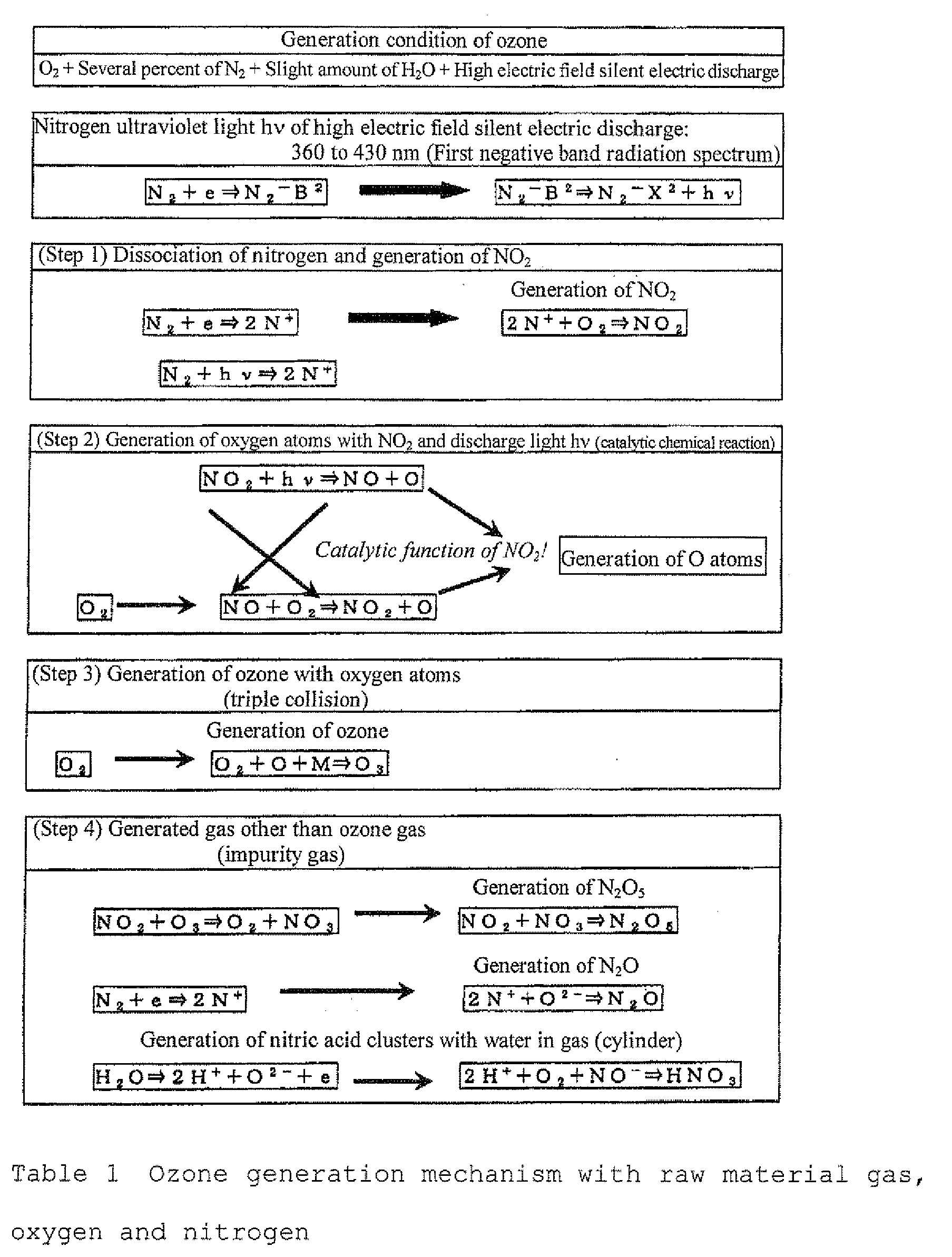
- That is, a large amount of O atoms is generated through catalytic function of NOx clusters, such as NO2, so as to generate ozone. Accordingly, upon considering that an ozone concentration (about several percent by volume to 20% by volume), which is about 10,000 times the NO2 amount, is generated through the catalytic function of several tens ppm of NO2 and the photochemical reaction of the discharge light, the phenomenon is physically appropriate, and it can be explained that ozone can be sufficiently generated. It has been considered that high energy electrons generated through short gap silent electric discharge with a gap of 0.1 mm and an oxygen gas collide with each other to generate O atoms. However, although high energy electrons capable of dissociating O atoms can be generated through silent electric discharge, the density of the high energy electrons capable of dissociating O atoms during discharge is about from 109 to 1010 per unit volume (per m3), and such a mechanism has been believed without explanation that ozone of from several percent by volume to 20% by volume (0.3 × 10¹⁹ per cm3) is generated with such an extremely small electron density. In recent years, an ozone generator is developed by selecting a photocatalytic substance capable of substituting the catalytic function of the NOx clusters, such as NO2, assuming the aforementioned principle, and a nitrogen-free ozone generator is commercially available.
However, an ozone gas generated from an ordinary ozone generator contains NOx since nitrogen is contained in a raw material gas. The NOx gas output from the ozone generator is almost N2O5, N2O and nitric acid clusters HNO3. N2O5 is liquefied at 0°C or less to be N2O5 clusters present in the ozone gas. N2O has a melting point around -90°C. - Research on vapor pressure characteristics of the gas species contained in the ozone generator reveals
Fig. 14 . Accordingly, since liquefaction occurs at 80 k (-193°C) in an ozone concentrating apparatus, in which ozone is concentrated by liquefaction, not only ozone but also an N2O gas, nitric acid clusters HNO3 and N2O5 clusters are liquefied and vaporized at 100 K (-173°C), whereby a concentrated ozone gas containing substantially no NOx can be obtained. In this method, however, upon liquefying, an N2O gas, nitric acid clusters HNO3 and N2O5 clusters in a liquefied state remain in the apparatus, and an N2O gas, nitric acid clusters HNO3 and N2O5 clusters are necessarily removed (removal of NOx) periodically. - In an adsorption type ozone concentrating apparatus concentrating ozone by adsorption, since adsorption occurs at about -60°C, in an ozonized oxygen gas generated from the ozone generator, not only ozone but also an N2O gas, nitric acid clusters HNO3 and N2O5 clusters are adsorbed. In order to desorb ozone having been adsorbed at 0°C, an N2O gas having a higher temperature of vapor pressure characteristics than an ozone gas is output as a mixture with an ozone gas in a concentrated ozone gas. Nitric acid clusters HNO3 and N2O5 clusters are partially vaporized and output in a concentrated ozone gas as nitric acid clusters HNO3 and N2O5 clusters, but almost entire acid clusters HNO3 and N2O5 clusters remains as being adsorbed on the adsorbent. Accordingly, HNO3 and N2O5 are accumulated in the adsorbent to cause deterioration in performance of the adsorbent.
- In an ozone concentrating apparatus, in which ozone is selectively condensed, and condensed ozone is vaporized in the same space, or an oxygen transmission membrane (130) selectively transmitting an oxygen gas other than an ozone gas is used, so as to remove an oxygen gas in an ozonized gas, for example, ozone is selectively condensed by utilizing adsorption at a low temperature of -60°C, and condensed ozone is vaporized at -0°C, whereby an N2O gas, nitric acid clusters HNO3 and N2O5 clusters generated in the ozone generator are contained in the concentrated ozone gas, but an N2O gas, nitric acid clusters HNO3 and N2O3 clusters are not accumulated in the ozone concentrating apparatus. Accordingly, it is not necessary to remove NOx periodically, which is the case in a liquid type ozone concentrating apparatus, and there is no problem in deterioration in performance of an adsorbent, which is the case in an adsorption type ozone concentrating apparatus, whereby an apparatus having higher practicality can be provided.
- In an ozone CVD apparatus for forming an interlayer dielectric film as a semiconductor production apparatus, when an N2O gas, nitric acid clusters HNO3 and N2O5 clusters are contained in an ozonized oxygen gas, they causes deposition of a metallic contamination substance, such as metallic chromium and manganese, at a part where the ozonized oxygen gas is in contact with the part of the apparatus in the gas, and the metallic contamination invades in the oxide film to deteriorate insulating property of the oxide film, which brings about increase in leakage electric current. Thus, there is a problem of failing to form an oxide film with good quality. Such an ozone gas is demanded that is decreased as much as possible in amount of NOx, which causes deposition of a metallic contamination substance. Accordingly, in the ozone concentrating apparatus of the invention, a nitrogen-free ozone generator using a photocatalytic substance capable of generating ozone by feeding a high purity oxygen gas of 99.999% or more containing no nitrogen is used as the ozone generator, whereby a concentrated ozonized oxygen gas that is considerably decreased in amount of NOx can be provided.
-
Fig. 15 is a diagram showing a nitrogen addition rate of a raw material gas in an ozone generator and an NO2 amount (converted value) generated by the ozone generator. As a means for measuring NOx contained in an ozonized oxygen gas having ozone generated, the generated ozonized oxygen gas is bubbled in pure water to dissolve NOx in pure water as nitric acid (HNO3), and the ion amount of NO3 - dissolved in pure water is measured to measure NOx generated in the ozone generator. The NO2 gas amount generated in the ozone generator can be calculated from the NO3 - ion amount. - In
Fig. 15 , thecharacteristic curve 2009 is calculated from Table 3 ofPatent Document 8. Thecharacteristic curve 2010 shows the characteristics obtained by measuring in the apparatus of the invention. The figure shows that NO2 is generated in an amount of 100, 000 vol/ppb at a nitrogen addition rate of about 1%, and when the nitrogen addition rate is decreased, the NO2 amount is decreased. In a nitrogen-free ozone generator generating ozone only with a high purity oxygen gas of 99.99% or more, the nitrogen content is 0.005% or less, and the NO2 amount generated in this case is 0.001 vol/ppb (region 2011) or less, i.e., ozonized oxygen to be fed has a considerably small NOx amount, so as to provide a high concentration ozonized oxygen gas containing substantially no NOx in an ozone gas concentrated. -
Figs. 3-a and3-b show anozone concentrating system 100 of anembodiment 4 of the invention. As compared to theembodiment 1 described with reference toFig. 1 , this embodiment shows an example where the constitution of the freezingmachine 14, the arrangement of theparticle material 13 for condensation and vaporization in the concentratingchambers Fig. 3-a , the freezing machine is divided into two, 14a and 14b, the freezingmachine 14a is disposed at the upper part of the concentratingchambers machine 14b is disposed at the lower part thereof. In the upper part, the cooling temperature is the optimum temperature for selectively condensing an ozone gas, thereby making an ozone condensation zone. In the lower part, the cooling temperature is a temperature range where ozone is gradually vaporized, thereby making an ozone vaporization zone. - In
Fig. 3-b , the freezing machine is divided into three, 14a, 14b and 14c, the freezingmachine 14a is disposed at the upper part of the concentratingchambers machine 14b is disposed at the lower part thereof, and the freezingmachine 14c is disposed at the bottom part of the concentratingchambers chambers chambers - In order to prevent liquid ozone accumulated on the bottom part from being rapidly vaporized, such a constitution is provided that the particle material for condensation and vaporization is also filled in the bottom part to increase the surface area of the particle material for condensation and vaporization at a low temperature, whereby rapid gasification is prevented.
In the invention, while a system for concentrating an ozone gas with one stage of condensation-vaporization zone is shown, it is possible that further several stages of concentrating chambers are provided for the diluted ozone gas, whereby nearly 100% of the ozone gas generated from the ozone generator is condensed to obtain high concentration ozonized oxygen. - While a concentrating system of an ozonized oxygen gas has been described in the
aforementioned embodiments 1 to 4, the invention may be utilized as such a measure, as another example, that air containing a NOx gas, Freon gas or a carbon dioxide gas is cleaned (diluted) or concentrated to improve efficiency of decomposition process of a NOx gas, Freon gas or a carbon dioxide gas. A NOx gas contained in air mainly includes NO2, N2O5, N2O, NO and HNO3. N2O5 and HNO3 have a high melting point and are present in a cluster state (vapor state) but not in a gas state around 0°C. The melting points of NO2, N2O and NO are about -60°C, -140°C and -180°C, respectively, as shown in the vapor pressure characteristics inFig. 14 . - A Freon gas discharged to the atmosphere has a melting point of about from -70 to -30°C. A carbon dioxide gas (CO2) has a melting point of about -140°C as shown in vapor pressure characteristics in
Fig. 16 . Accordingly, in order to dilute (clean) or concentrate these gases, it is necessary to change the cooling temperature of the concentrating chamber depending on the target gas for diluting or concentrating. The gas having been concentrated is a corrosive gas, and it is necessary to select materials having sufficient corrosion resistance for parts, such as pipings and valves, for the concentrated gas. -
Fig. 17 is an illustration showing a constitution of an apparatus for cleaning or concentrating air containing a NOx gas, a Freon gas and a carbon dioxide gas according to theembodiment 5.
In the figure, numeral 6 denotes a compressor for compressing an atmospheric gas, 171 denotes a controlling valve for feeding the compressed atmospheric gas under controlling in flow rate, 172, 173, 174 and 176 are valves for controlling pressures ingas concentrations systems Numerals - The
gas concentrating apparatuses ozone concentrating system 100 shown inFig. 1 , in which upper parts of the chambers in thegas concentrating apparatuses compressor 6, and then continuously fed (Q1) to the gas concentrating apparatus with the controllingvalve 171. - After obtaining the state, the flow rate of the diluted gas retrieved from the upper part is controlled with the
valve 175, and a concentrated gas is retrieved at a flow rate Q3 by controlling the pressures of the gas concentrating apparatuses I, II and III by controlling thevalves gas decomposing apparatus 81. The flow rates Q2 and Q3 of dilution (cleaning) with respect to the fed flow amount Q1 are controlled to have the following flow rate balance by controlling thevalves flow rate meter -
- Q1:
- 40 L/min
- Q2:
- 30 L/min
- QA:
- 6 L/min,
- QB:
- 3 L/min,
- QC:
- 1 L/min
- As having been described, in the apparatus for cleaning and concentrating air containing a NOx gas, a Freon gas and a carbon dioxide gas, it is necessary that concentrating and diluting of a considerably large flow rate are demanded, and the apparatus is inexpensive, while the quality, such as controllability and stability, may be low, and such measures as explosion prevention are not necessary, as compared to the ozone concentrating system apparatus. In order to realize the apparatus, since a mass flow rate controller (MFC) and an automatic pressure controller (APC), which are used in the ozone concentrating system, cannot be used, all the flow rates in the respective parts are manually controlled with the controlling valves and flow rate meters as shown in
Fig. 17 .
In order to increase the cleanliness degree of the diluted (cleaned) gas, a multistage constitution with the second and third step gas concentrating apparatuses for further diluting the diluted gas from the first step. - In the ozone concentrating apparatus of the invention, a mass flow rate controller (MFC) is provided on the side for retrieving diluted ozone, and an automatic pressure controller (APC) is provided on the side for retrieving concentrated ozone, so as to maintain the pressure in the zone concentrating chamber constant and to control the flow rate of diluted ozone, whereby the concentrated ozone flow rate is distributed, but the same advantage as in the invention can be obtained by providing a mass flow rate controller (MFC) on the side for retrieving concentrated ozone, and APC on the side for retrieving diluted ozone.
- The flow rate on the side for retrieving diluted ozone is controlled with MFC, but the same advantage as in the invention can be obtained by controlling the flow rate with a valve instead of MFC.
- APC is used on the side for retrieving concentrated ozone for automatically control the flow rate for retrieving to maintain the pressure in the ozone concentrating chamber constant, but the same advantage as in the invention can be obtained by making the pressure in the ozone concentrating chamber constant with a combination of MFC and a pressure gage, or a flow rate controlling valve and a pressure gage, instead of APC.
- The performance of the efficiency in concentrating ozone and the performance, such as compactness, inexpensiveness and light weight, of the apparatus in the invention can be further improved by optimizing the design in the invention including the constitution of the freezing machine, the size and amount of the material for condensation and vaporization in the ozone concentrating chamber, the diameter, material and length of the ozone concentrating chamber, the length where the material for condensation and vaporization is filled, which are determined by the thermal boundary layer, viscosity, specific heat and thermal conductivity in the stream of the ozonized oxygen gas, and the thermal conductivity, specific heat and the like of the ozone concentrating chamber, in addition to the constitution and functions of the ozone concentrating chamber of the invention.
- The invention contributes to improvement in production efficiency by applying to, in addition to the semiconductor production technique, such industrial fields as the field of supplying an ozone gas, the field of removing CO2 in the atmospheric air, and the field of removing NOx and Freon contained in a waste gas.
Claims (23)
- An apparatus for concentrating and diluting a specific gas characterized by comprising;
a specific gas concentrating system including a chamber having filled therein a particle material for condensation and vaporization capable of selectively condensing the specific gas or having equipped therein a gas transmission member selectively transmitting other gases than the specific gas and a freezing machine that cools the specific gas fed to the chamber to a predetermined cool temperature, and
a gas feeding and retrieving system having a feeding port feeding a gas containing plural gas species, a diluted gas retrieving port retrieving a gas containing the specific gas having been diluted, and a concentrated gas retrieving port retrieving a gas containing the specific gas having been concentrated,
wherein the diluted gas retrieving part of the gas fed to the chamber is performed dilution of the specific gas by selectively condensing the specific gas on a surface of the particle material or the gas transmission member through cooling with the freezing machine or by selectively transmitting the other gases than the specific gas by the gas transmission member, and
wherein the concentrated gas retrieving part of the gas fed to the chamber is performed concentration of the specific gas by vaporizing the condensed gas on the surface of the particle material or the gas transmission member through heating a surrounding of the concentrated gas retrieving part, thereby continuously retrieving the gas containing the specific gas having been diluted through the diluted gas retrieving part of the chamber or continuously retrieving the gas containing the specific gas having been concentrated through the concentrated gas retrieving part of the chamber. - The apparatus for concentrating and diluting a specific gas according to claim 1, wherein said freezing machine is provided on the diluted gas retrieving side of the chamber and cool the gas to a cool temperature accelerating condensation of the specific gas or transmission of other gases than the specific gas on the surface of the particle material or the gas transmission member.
- The apparatus for concentrating and diluting a specific gas according to claim 1 or 2, characterized by, in the apparatus for concentrating and diluting a specific gas containing the chamber having filled therein the particle material, providing at least one of an automatic pressure controller (APC) controlling an inner pressure of the chamber or a gas pressure controlling valve and a mass flow rate controller (MFC) controlling a flow rate of a gas retrieved from the chamber or a gas flow rate controlling valve, on either of the gas retrieving port of the diluted gas retrieving part or the gas retrieving port of the concentrated gas retrieving part of the chamber, and continuously retrieving through them a gas containing the specific gas having been diluted from the diluted gas retrieving part of the chamber and a gas containing the specific gas having been concentrated from the concentrated gas retrieving part of the chamber.
- The apparatus for concentrating and diluting a specific gas according to claim 1 or 2, characterized by, in the apparatus for concentrating and diluting a specific gas containing the chamber having filled therein the gas transmission member, providing an automatic pressure controller I (APC I) or a gas pressure controlling valve I controlling an inner pressure P1 of the chamber of a diluted gas having removed the specific gas by transmitting other gases than the specific gas at the diluted gas retrieving part of the chamber, and providing an automatic pressure controller II (APC II) or a gas pressure controlling valve II controlling an inner pressure P2 at the concentrated gas retrieving part of the chamber, thereby producing a gas pressure difference ΔP (= P2 - P1) on sides on the gas transmitting members, continuously retrieving through them a gas containing the specific gas having been diluted from the diluted gas retrieving part of the chamber and a gas containing the specific gas having been concentrated from the concentrated gas retrieving part of the chamber.
- The apparatus for concentrating and diluting a specific gas according to claim 1 or 2, characterized in that a temperature distribution is provided in a vertical direction of the chamber by a constitution of increasing upward a thermal insulation capability of a thermal insulating function provided on a periphery of the chamber.
- The apparatus for concentrating and diluting a specific gas according to claim 1 or 2, characterized in that the particle material for condensation and vaporization filled in the chamber is made to be a spherical shape with a part of the side surface thereof being flattened, and is filled in layers to make the flattened parts of the spherical particle material in contact with each other.
- The apparatus for concentrating and diluting a specific gas according to claim 5, characterized in that a material of the particle material for condensation and vaporization is glass, ceramics or a metal that does not undergo chemical reaction with the gas containing plural gas species.
- The apparatus for concentrating and diluting a specific gas according to claim 6, characterized in that a material of the particle material for condensation and vaporization is glass, ceramics or a resin material having low thermal conductivity, and a surface of the particles is coated with a metallic film having high thermal conductivity that does not undergo chemical reaction with the gas containing plural gas species.
- The apparatus for concentrating and diluting a specific gas according to claim 1, characterized in that the gas containing plural gas species fed to the apparatus for concentrating and diluting is an ozonized gas containing an ozone gas, and ozone is concentrated based on a concentration of the fed ozonized gasan ozone gas having a high concentration.

- The apparatus for concentrating and diluting a specific gas according to claim 4, characterized in that the gas containing plural gas species fed to the apparatus for concentrating and diluting is an ozonized gas containing an ozone gas, the inner pressure P1 of at the retrieving part of the diluted gas is set to the atmospheric pressure (0 MPa) or more, and the pressure P2 at the concentrated gas retrieving part is set to a range of from 0.1 MPa to 0.5 MPa, to provide a gas pressure difference in ΔP (= P2 - P1) between sides of the gas transmission members of 0.1 MPa or more.
- The apparatus for concentrating and diluting a specific gas according to claim 4, characterized in that the gas containing plural gas species fed to the apparatus for concentrating and diluting is an ozonized gas containing an ozone gas, and the gas transmission member is constituted with a Teflon (a trade name) membrane material or a ceramic material, to transmit selectively only an oxygen gas contained in the ozonized gas with the gas transmission member.
- The apparatus for concentrating and diluting a specific gas according to claim 1, characterized in that the gas containing plural gas species fed to the apparatus for concentrating and diluting is an ozonized gas containing an ozone gas, and the freezing machine is provided in a vicinity of the chamber and cools the particle material or the gas transmission member to a prescribed low temperature by setting the cooling temperature of the chamber to -100°C or more.
- The apparatus for concentrating and diluting a specific gas according to claim 1, characterized in that the gas containing plural gas species fed to the apparatus for concentrating and diluting is an ozonized gas containing an ozone gas, and the ozonized gas diluted gas (oxygen gas) retrieved from the diluted gas retrieving part of the chamber is made to have a high pressure with a gas compressor to reuse the gas as a raw material gas for an ozone gas generator.
- The apparatus for concentrating and diluting a specific gas according to claim 9, characterized in that the gas containing plural gas species fed to the ozone concentrating system is an ozonized gas containing an ozone gas, an ozone generator generating an ozonized oxygen gas is provided, and the ozonized oxygen gas generated from the ozone generator is fed as the gas containing plural gas species to a center part of the ozone concentrating system.
- The apparatus for concentrating and diluting a specific gas according to claim 1, characterized in that the gas containing plural gas species fed to the ozone concentrating system is an ozonized gas containing an ozone gas, and as an ozone generator generating the ozonized oxygen gas, a nitrogen-free ozone generator generating an ozone gas from a high purity oxygen gas having an addition amount of a nitrogen gas of 1 ppm or less is used.
- The apparatus for concentrating and diluting a specific gas according to claim 1, characterized in that the gas containing plural gas species fed to the apparatus for concentrating and diluting is air containing at least one of a carbon dioxide gas, a NOx gas and a Freon gas, the gas contained in air is concentrated to separate into air containing the gas having been concentrated and air containing the gas having been diluted (cleaned).
- The apparatus for concentrating and diluting a specific gas according to claim 1, characterized in that the apparatuses for concentrating and diluting a specific gas are provided plurally as a multistage cascade.
- The method for concentrating and diluting a specific gas from a gas containing plural gas species characterized by introducing a specific gas containing the plural gas species to a gas concentrating and diluting chamber having filled therein a particle material for condensation and vaporization the specific gas or having equipped therein a gas transmission member selectively transmitting other gases than the specific gas, with a function of cooling the gas in the chamber equipped therein; cooling the gas in the chamber with a gas feeding and retrieving system having a function of retrieving a gas containing the specific gas having been diluted or retrieving a gas containing the specific gas having been concentrated, thereby selectively condensing only the specific gas or selectively transmitting the other gases than the specific gas on a surface of the particle material for condensation and vaporization or the gas transmission member, so as to realize dilution of the specific gas by a diluted gas retrieving part of the chamber; and heating a surrounding of a concentrated gas retrieving part of the chamber while streaming down a liquid condensed on the surface of the particle material to a lower part of the chamber by gravitation, thereby vaporizing the condensed gas on the surface of the particle material to realize high concentration of the specific gas at a concentrated gas retrieving part of the chamber, and continuously retrieving a gas containing the specific gas having been diluted from the diluted gas retrieving part of the chamber or a gas containing the specific gas having been concentrated from the concentrated gas retrieving part of the chamber.
- The method for concentrating or diluting a specific gas according to claim 18, characterized by, in the apparatus for concentrating and diluting a specific gas containing the chamber having filled therein the particle material, providing at least one of an automatic pressure controller (APC) controlling an inner pressure of the chamber and a mass flow rate controller (MFC) controlling a flow rate of a gas retrieved from the chamber, on at least one of the gas retrieving port of the diluted gas retrieving part and the gas retrieving port of the concentrated gas retrieving part of the chamber, automatically controlling an inner pressure of the chamber to a prescribed pressure with the automatic pressure controller (APC), and setting a flow rate of a gas containing the specific gas having been retrieved from the diluted gas retrieving part of the chamber through them with the mass flow rate controller (MFC), thereby enabling automatic control of a concentrated gas concentration and flow rate upon continuously retrieving a gas containing the specific gas having been concentrated.
- The method for concentrating or diluting a specific gas according to claim 18, characterized by, in the apparatus for concentrating and diluting a specific gas containing the chamber having filled therein the gas transmission member, providing an automatic pressure controller I (APC I) or a gas pressure controlling valve I controlling an inner pressure P1 of the chamber of a diluted gas having the specific gas removed by transmitting other gases than the specific gas at the diluted gas retrieving part of the chamber, and providing an automatic pressure controller II (APC II) or a gas pressure controlling valve II controlling an inner pressure P2 at the concentrated gas retrieving part of the chamber, thereby producing a gas pressure difference ΔP (= P2 - P1) on sides between the gas transmitting members, continuously retrieving to the outside a gas containing the specific gas having been diluted from the diluted gas retrieving part of the chamber and a gas containing the specific gas having been concentrated from the concentrated gas retrieving part of the chamber through them, varying at least one set pressures of the automatic pressure controller I (APC I) and the automatic pressure controller II (APC II), thereby enabling control of a concentrated gas concentration upon continuously retrieving the gas containing the specific gas having been concentrated.
- The method for concentrating or diluting a specific gas according to claim 18, characterized in that the liquefied gas concentrating and diluting chambers are provided plurally as a multistage cascade to improve the degree of concentrating of the concentrated gas of the specific gas and the degree of diluting of the diluted gas of the specific gas.
- The method for concentrating or diluting a specific gas according to claim 18, characterized in that the gas containing plural gas species fed to the chamber for concentrating and diluting is an ozonized gas containing an ozone gas, and ozone in the ozonized gas is concentrated to an ozonized gas having a high concentration.
- The method for concentrating or diluting a specific gas according to claim 18, characterized in that the gas containing plural gas species fed to the chamber for concentrating and diluting is air containing at least one of a carbon dioxide gas, a NOx gas and a Freon gas, and the gas contained in air is concentrated to separate into air containing the gas having been concentrated and air containing the gas having been diluted (cleaned).
Applications Claiming Priority (2)
| Application Number | Priority Date | Filing Date | Title |
|---|---|---|---|
| PCT/JP2006/313309 WO2008004278A1 (en) | 2006-07-04 | 2006-07-04 | Apparatus for concentrating/diluting specific gas and method of concentrating/diluting specific gas |
| PCT/JP2006/323807 WO2008004321A1 (en) | 2006-07-04 | 2006-11-29 | Apparatus and method for the concentration and dilution of specific gas |
Publications (3)
| Publication Number | Publication Date |
|---|---|
| EP2036600A1 true EP2036600A1 (en) | 2009-03-18 |
| EP2036600A4 EP2036600A4 (en) | 2012-01-18 |
| EP2036600B1 EP2036600B1 (en) | 2019-02-27 |
Family
ID=38894257
Family Applications (1)
| Application Number | Title | Priority Date | Filing Date |
|---|---|---|---|
| EP06833611.4A Active EP2036600B1 (en) | 2006-07-04 | 2006-11-29 | Apparatus and method for the concentration and dilution of specific gas |
Country Status (6)
| Country | Link |
|---|---|
| US (2) | US8500874B2 (en) |
| EP (1) | EP2036600B1 (en) |
| KR (1) | KR101055136B1 (en) |
| CN (1) | CN101389387B (en) |
| TW (1) | TWI329031B (en) |
| WO (2) | WO2008004278A1 (en) |
Cited By (335)
| Publication number | Priority date | Publication date | Assignee | Title |
|---|---|---|---|---|
| US20140346650A1 (en) * | 2009-08-14 | 2014-11-27 | Asm Ip Holding B.V. | Systems and methods for thin-film deposition of metal oxides using excited nitrogen-oxygen species |
| US9167625B2 (en) | 2011-11-23 | 2015-10-20 | Asm Ip Holding B.V. | Radiation shielding for a substrate holder |
| US9169975B2 (en) | 2012-08-28 | 2015-10-27 | Asm Ip Holding B.V. | Systems and methods for mass flow controller verification |
| US9177784B2 (en) | 2012-05-07 | 2015-11-03 | Asm Ip Holdings B.V. | Semiconductor device dielectric interface layer |
| US9202727B2 (en) | 2012-03-02 | 2015-12-01 | ASM IP Holding | Susceptor heater shim |
| US9228259B2 (en) | 2013-02-01 | 2016-01-05 | Asm Ip Holding B.V. | Method for treatment of deposition reactor |
| US9240412B2 (en) | 2013-09-27 | 2016-01-19 | Asm Ip Holding B.V. | Semiconductor structure and device and methods of forming same using selective epitaxial process |
| US9299595B2 (en) | 2012-06-27 | 2016-03-29 | Asm Ip Holding B.V. | Susceptor heater and method of heating a substrate |
| US9324811B2 (en) | 2012-09-26 | 2016-04-26 | Asm Ip Holding B.V. | Structures and devices including a tensile-stressed silicon arsenic layer and methods of forming same |
| US9341296B2 (en) | 2011-10-27 | 2016-05-17 | Asm America, Inc. | Heater jacket for a fluid line |
| US9384987B2 (en) | 2012-04-04 | 2016-07-05 | Asm Ip Holding B.V. | Metal oxide protective layer for a semiconductor device |
| US9394608B2 (en) | 2009-04-06 | 2016-07-19 | Asm America, Inc. | Semiconductor processing reactor and components thereof |
| US9396934B2 (en) | 2013-08-14 | 2016-07-19 | Asm Ip Holding B.V. | Methods of forming films including germanium tin and structures and devices including the films |
| US9404587B2 (en) | 2014-04-24 | 2016-08-02 | ASM IP Holding B.V | Lockout tagout for semiconductor vacuum valve |
| US9412564B2 (en) | 2013-07-22 | 2016-08-09 | Asm Ip Holding B.V. | Semiconductor reaction chamber with plasma capabilities |
| US9447498B2 (en) | 2014-03-18 | 2016-09-20 | Asm Ip Holding B.V. | Method for performing uniform processing in gas system-sharing multiple reaction chambers |
| US9484191B2 (en) | 2013-03-08 | 2016-11-01 | Asm Ip Holding B.V. | Pulsed remote plasma method and system |
| US9558931B2 (en) | 2012-07-27 | 2017-01-31 | Asm Ip Holding B.V. | System and method for gas-phase sulfur passivation of a semiconductor surface |
| US9589770B2 (en) | 2013-03-08 | 2017-03-07 | Asm Ip Holding B.V. | Method and systems for in-situ formation of intermediate reactive species |
| US9605343B2 (en) | 2013-11-13 | 2017-03-28 | Asm Ip Holding B.V. | Method for forming conformal carbon films, structures conformal carbon film, and system of forming same |
| US9605342B2 (en) | 2012-09-12 | 2017-03-28 | Asm Ip Holding B.V. | Process gas management for an inductively-coupled plasma deposition reactor |
| US9607837B1 (en) | 2015-12-21 | 2017-03-28 | Asm Ip Holding B.V. | Method for forming silicon oxide cap layer for solid state diffusion process |
| US9627221B1 (en) | 2015-12-28 | 2017-04-18 | Asm Ip Holding B.V. | Continuous process incorporating atomic layer etching |
| US9640416B2 (en) | 2012-12-26 | 2017-05-02 | Asm Ip Holding B.V. | Single-and dual-chamber module-attachable wafer-handling chamber |
| US9647114B2 (en) | 2015-08-14 | 2017-05-09 | Asm Ip Holding B.V. | Methods of forming highly p-type doped germanium tin films and structures and devices including the films |
| US9657845B2 (en) | 2014-10-07 | 2017-05-23 | Asm Ip Holding B.V. | Variable conductance gas distribution apparatus and method |
| US9659799B2 (en) | 2012-08-28 | 2017-05-23 | Asm Ip Holding B.V. | Systems and methods for dynamic semiconductor process scheduling |
| US9711345B2 (en) | 2015-08-25 | 2017-07-18 | Asm Ip Holding B.V. | Method for forming aluminum nitride-based film by PEALD |
| US9735024B2 (en) | 2015-12-28 | 2017-08-15 | Asm Ip Holding B.V. | Method of atomic layer etching using functional group-containing fluorocarbon |
| US9754779B1 (en) | 2016-02-19 | 2017-09-05 | Asm Ip Holding B.V. | Method for forming silicon nitride film selectively on sidewalls or flat surfaces of trenches |
| US9793115B2 (en) | 2013-08-14 | 2017-10-17 | Asm Ip Holding B.V. | Structures and devices including germanium-tin films and methods of forming same |
| US9793135B1 (en) | 2016-07-14 | 2017-10-17 | ASM IP Holding B.V | Method of cyclic dry etching using etchant film |
| US9793148B2 (en) | 2011-06-22 | 2017-10-17 | Asm Japan K.K. | Method for positioning wafers in multiple wafer transport |
| US9790595B2 (en) | 2013-07-12 | 2017-10-17 | Asm Ip Holding B.V. | Method and system to reduce outgassing in a reaction chamber |
| US9812320B1 (en) | 2016-07-28 | 2017-11-07 | Asm Ip Holding B.V. | Method and apparatus for filling a gap |
| US9859151B1 (en) | 2016-07-08 | 2018-01-02 | Asm Ip Holding B.V. | Selective film deposition method to form air gaps |
| US9887082B1 (en) | 2016-07-28 | 2018-02-06 | Asm Ip Holding B.V. | Method and apparatus for filling a gap |
| US9891521B2 (en) | 2014-11-19 | 2018-02-13 | Asm Ip Holding B.V. | Method for depositing thin film |
| US9890456B2 (en) | 2014-08-21 | 2018-02-13 | Asm Ip Holding B.V. | Method and system for in situ formation of gas-phase compounds |
| US9892908B2 (en) | 2011-10-28 | 2018-02-13 | Asm America, Inc. | Process feed management for semiconductor substrate processing |
| US9899405B2 (en) | 2014-12-22 | 2018-02-20 | Asm Ip Holding B.V. | Semiconductor device and manufacturing method thereof |
| US9899291B2 (en) | 2015-07-13 | 2018-02-20 | Asm Ip Holding B.V. | Method for protecting layer by forming hydrocarbon-based extremely thin film |
| US9909214B2 (en) | 2015-10-15 | 2018-03-06 | Asm Ip Holding B.V. | Method for depositing dielectric film in trenches by PEALD |
| US9916980B1 (en) | 2016-12-15 | 2018-03-13 | Asm Ip Holding B.V. | Method of forming a structure on a substrate |
| US9960072B2 (en) | 2015-09-29 | 2018-05-01 | Asm Ip Holding B.V. | Variable adjustment for precise matching of multiple chamber cavity housings |
| US10032628B2 (en) | 2016-05-02 | 2018-07-24 | Asm Ip Holding B.V. | Source/drain performance through conformal solid state doping |
| US10043661B2 (en) | 2015-07-13 | 2018-08-07 | Asm Ip Holding B.V. | Method for protecting layer by forming hydrocarbon-based extremely thin film |
| US10083836B2 (en) | 2015-07-24 | 2018-09-25 | Asm Ip Holding B.V. | Formation of boron-doped titanium metal films with high work function |
| US10087525B2 (en) | 2015-08-04 | 2018-10-02 | Asm Ip Holding B.V. | Variable gap hard stop design |
| US10090316B2 (en) | 2016-09-01 | 2018-10-02 | Asm Ip Holding B.V. | 3D stacked multilayer semiconductor memory using doped select transistor channel |
| US10087522B2 (en) | 2016-04-21 | 2018-10-02 | Asm Ip Holding B.V. | Deposition of metal borides |
| USD830981S1 (en) | 2017-04-07 | 2018-10-16 | Asm Ip Holding B.V. | Susceptor for semiconductor substrate processing apparatus |
| US10103040B1 (en) | 2017-03-31 | 2018-10-16 | Asm Ip Holding B.V. | Apparatus and method for manufacturing a semiconductor device |
| US10134757B2 (en) | 2016-11-07 | 2018-11-20 | Asm Ip Holding B.V. | Method of processing a substrate and a device manufactured by using the method |
| US10167557B2 (en) | 2014-03-18 | 2019-01-01 | Asm Ip Holding B.V. | Gas distribution system, reactor including the system, and methods of using the same |
| US10177025B2 (en) | 2016-07-28 | 2019-01-08 | Asm Ip Holding B.V. | Method and apparatus for filling a gap |
| US10179947B2 (en) | 2013-11-26 | 2019-01-15 | Asm Ip Holding B.V. | Method for forming conformal nitrided, oxidized, or carbonized dielectric film by atomic layer deposition |
| US10190213B2 (en) | 2016-04-21 | 2019-01-29 | Asm Ip Holding B.V. | Deposition of metal borides |
| US10211308B2 (en) | 2015-10-21 | 2019-02-19 | Asm Ip Holding B.V. | NbMC layers |
| US10229833B2 (en) | 2016-11-01 | 2019-03-12 | Asm Ip Holding B.V. | Methods for forming a transition metal nitride film on a substrate by atomic layer deposition and related semiconductor device structures |
| US10236177B1 (en) | 2017-08-22 | 2019-03-19 | ASM IP Holding B.V.. | Methods for depositing a doped germanium tin semiconductor and related semiconductor device structures |
| US10249524B2 (en) | 2017-08-09 | 2019-04-02 | Asm Ip Holding B.V. | Cassette holder assembly for a substrate cassette and holding member for use in such assembly |
| US10249577B2 (en) | 2016-05-17 | 2019-04-02 | Asm Ip Holding B.V. | Method of forming metal interconnection and method of fabricating semiconductor apparatus using the method |
| US10262859B2 (en) | 2016-03-24 | 2019-04-16 | Asm Ip Holding B.V. | Process for forming a film on a substrate using multi-port injection assemblies |
| US10269558B2 (en) | 2016-12-22 | 2019-04-23 | Asm Ip Holding B.V. | Method of forming a structure on a substrate |
| US10276355B2 (en) | 2015-03-12 | 2019-04-30 | Asm Ip Holding B.V. | Multi-zone reactor, system including the reactor, and method of using the same |
| US10283353B2 (en) | 2017-03-29 | 2019-05-07 | Asm Ip Holding B.V. | Method of reforming insulating film deposited on substrate with recess pattern |
| US10312055B2 (en) | 2017-07-26 | 2019-06-04 | Asm Ip Holding B.V. | Method of depositing film by PEALD using negative bias |
| US10319588B2 (en) | 2017-10-10 | 2019-06-11 | Asm Ip Holding B.V. | Method for depositing a metal chalcogenide on a substrate by cyclical deposition |
| US10322384B2 (en) | 2015-11-09 | 2019-06-18 | Asm Ip Holding B.V. | Counter flow mixer for process chamber |
| US10340135B2 (en) | 2016-11-28 | 2019-07-02 | Asm Ip Holding B.V. | Method of topologically restricted plasma-enhanced cyclic deposition of silicon or metal nitride |
| US10343920B2 (en) | 2016-03-18 | 2019-07-09 | Asm Ip Holding B.V. | Aligned carbon nanotubes |
| US10367080B2 (en) | 2016-05-02 | 2019-07-30 | Asm Ip Holding B.V. | Method of forming a germanium oxynitride film |
| US10364496B2 (en) | 2011-06-27 | 2019-07-30 | Asm Ip Holding B.V. | Dual section module having shared and unshared mass flow controllers |
| US10381226B2 (en) | 2016-07-27 | 2019-08-13 | Asm Ip Holding B.V. | Method of processing substrate |
| US10378106B2 (en) | 2008-11-14 | 2019-08-13 | Asm Ip Holding B.V. | Method of forming insulation film by modified PEALD |
| US10381219B1 (en) | 2018-10-25 | 2019-08-13 | Asm Ip Holding B.V. | Methods for forming a silicon nitride film |
| US10388509B2 (en) | 2016-06-28 | 2019-08-20 | Asm Ip Holding B.V. | Formation of epitaxial layers via dislocation filtering |
| US10388513B1 (en) | 2018-07-03 | 2019-08-20 | Asm Ip Holding B.V. | Method for depositing silicon-free carbon-containing film as gap-fill layer by pulse plasma-assisted deposition |
| US10395919B2 (en) | 2016-07-28 | 2019-08-27 | Asm Ip Holding B.V. | Method and apparatus for filling a gap |
| US10403504B2 (en) | 2017-10-05 | 2019-09-03 | Asm Ip Holding B.V. | Method for selectively depositing a metallic film on a substrate |
| US10410943B2 (en) | 2016-10-13 | 2019-09-10 | Asm Ip Holding B.V. | Method for passivating a surface of a semiconductor and related systems |
| US10435790B2 (en) | 2016-11-01 | 2019-10-08 | Asm Ip Holding B.V. | Method of subatmospheric plasma-enhanced ALD using capacitively coupled electrodes with narrow gap |
| US10446393B2 (en) | 2017-05-08 | 2019-10-15 | Asm Ip Holding B.V. | Methods for forming silicon-containing epitaxial layers and related semiconductor device structures |
| US10458018B2 (en) | 2015-06-26 | 2019-10-29 | Asm Ip Holding B.V. | Structures including metal carbide material, devices including the structures, and methods of forming same |
| US10468261B2 (en) | 2017-02-15 | 2019-11-05 | Asm Ip Holding B.V. | Methods for forming a metallic film on a substrate by cyclical deposition and related semiconductor device structures |
| US10468251B2 (en) | 2016-02-19 | 2019-11-05 | Asm Ip Holding B.V. | Method for forming spacers using silicon nitride film for spacer-defined multiple patterning |
| US10483099B1 (en) | 2018-07-26 | 2019-11-19 | Asm Ip Holding B.V. | Method for forming thermally stable organosilicon polymer film |
| US10504742B2 (en) | 2017-05-31 | 2019-12-10 | Asm Ip Holding B.V. | Method of atomic layer etching using hydrogen plasma |
| US10501866B2 (en) | 2016-03-09 | 2019-12-10 | Asm Ip Holding B.V. | Gas distribution apparatus for improved film uniformity in an epitaxial system |
| US10510536B2 (en) | 2018-03-29 | 2019-12-17 | Asm Ip Holding B.V. | Method of depositing a co-doped polysilicon film on a surface of a substrate within a reaction chamber |
| US10529542B2 (en) | 2015-03-11 | 2020-01-07 | Asm Ip Holdings B.V. | Cross-flow reactor and method |
| US10529563B2 (en) | 2017-03-29 | 2020-01-07 | Asm Ip Holdings B.V. | Method for forming doped metal oxide films on a substrate by cyclical deposition and related semiconductor device structures |
| US10529554B2 (en) | 2016-02-19 | 2020-01-07 | Asm Ip Holding B.V. | Method for forming silicon nitride film selectively on sidewalls or flat surfaces of trenches |
| US10535516B2 (en) | 2018-02-01 | 2020-01-14 | Asm Ip Holdings B.V. | Method for depositing a semiconductor structure on a surface of a substrate and related semiconductor structures |
| US10541333B2 (en) | 2017-07-19 | 2020-01-21 | Asm Ip Holding B.V. | Method for depositing a group IV semiconductor and related semiconductor device structures |
| US10559458B1 (en) | 2018-11-26 | 2020-02-11 | Asm Ip Holding B.V. | Method of forming oxynitride film |
| US10590535B2 (en) | 2017-07-26 | 2020-03-17 | Asm Ip Holdings B.V. | Chemical treatment, deposition and/or infiltration apparatus and method for using the same |
| US10600673B2 (en) | 2015-07-07 | 2020-03-24 | Asm Ip Holding B.V. | Magnetic susceptor to baseplate seal |
| US10607895B2 (en) | 2017-09-18 | 2020-03-31 | Asm Ip Holdings B.V. | Method for forming a semiconductor device structure comprising a gate fill metal |
| US10605530B2 (en) | 2017-07-26 | 2020-03-31 | Asm Ip Holding B.V. | Assembly of a liner and a flange for a vertical furnace as well as the liner and the vertical furnace |
| US10612136B2 (en) | 2018-06-29 | 2020-04-07 | ASM IP Holding, B.V. | Temperature-controlled flange and reactor system including same |
| US10612137B2 (en) | 2016-07-08 | 2020-04-07 | Asm Ip Holdings B.V. | Organic reactants for atomic layer deposition |
| USD880437S1 (en) | 2018-02-01 | 2020-04-07 | Asm Ip Holding B.V. | Gas supply plate for semiconductor manufacturing apparatus |
| US10643904B2 (en) | 2016-11-01 | 2020-05-05 | Asm Ip Holdings B.V. | Methods for forming a semiconductor device and related semiconductor device structures |
| US10643826B2 (en) | 2016-10-26 | 2020-05-05 | Asm Ip Holdings B.V. | Methods for thermally calibrating reaction chambers |
| US10658205B2 (en) | 2017-09-28 | 2020-05-19 | Asm Ip Holdings B.V. | Chemical dispensing apparatus and methods for dispensing a chemical to a reaction chamber |
| US10658181B2 (en) | 2018-02-20 | 2020-05-19 | Asm Ip Holding B.V. | Method of spacer-defined direct patterning in semiconductor fabrication |
| US10655221B2 (en) | 2017-02-09 | 2020-05-19 | Asm Ip Holding B.V. | Method for depositing oxide film by thermal ALD and PEALD |
| US10685834B2 (en) | 2017-07-05 | 2020-06-16 | Asm Ip Holdings B.V. | Methods for forming a silicon germanium tin layer and related semiconductor device structures |
| US10683571B2 (en) | 2014-02-25 | 2020-06-16 | Asm Ip Holding B.V. | Gas supply manifold and method of supplying gases to chamber using same |
| US10692741B2 (en) | 2017-08-08 | 2020-06-23 | Asm Ip Holdings B.V. | Radiation shield |
| US10707106B2 (en) | 2011-06-06 | 2020-07-07 | Asm Ip Holding B.V. | High-throughput semiconductor-processing apparatus equipped with multiple dual-chamber modules |
| US10714385B2 (en) | 2016-07-19 | 2020-07-14 | Asm Ip Holding B.V. | Selective deposition of tungsten |
| US10714315B2 (en) | 2012-10-12 | 2020-07-14 | Asm Ip Holdings B.V. | Semiconductor reaction chamber showerhead |
| US10714350B2 (en) | 2016-11-01 | 2020-07-14 | ASM IP Holdings, B.V. | Methods for forming a transition metal niobium nitride film on a substrate by atomic layer deposition and related semiconductor device structures |
| US10714335B2 (en) | 2017-04-25 | 2020-07-14 | Asm Ip Holding B.V. | Method of depositing thin film and method of manufacturing semiconductor device |
| US10734244B2 (en) | 2017-11-16 | 2020-08-04 | Asm Ip Holding B.V. | Method of processing a substrate and a device manufactured by the same |
| US10731249B2 (en) | 2018-02-15 | 2020-08-04 | Asm Ip Holding B.V. | Method of forming a transition metal containing film on a substrate by a cyclical deposition process, a method for supplying a transition metal halide compound to a reaction chamber, and related vapor deposition apparatus |
| US10734497B2 (en) | 2017-07-18 | 2020-08-04 | Asm Ip Holding B.V. | Methods for forming a semiconductor device structure and related semiconductor device structures |
| US10755922B2 (en) | 2018-07-03 | 2020-08-25 | Asm Ip Holding B.V. | Method for depositing silicon-free carbon-containing film as gap-fill layer by pulse plasma-assisted deposition |
| US10767789B2 (en) | 2018-07-16 | 2020-09-08 | Asm Ip Holding B.V. | Diaphragm valves, valve components, and methods for forming valve components |
| US10770336B2 (en) | 2017-08-08 | 2020-09-08 | Asm Ip Holding B.V. | Substrate lift mechanism and reactor including same |
| US10770286B2 (en) | 2017-05-08 | 2020-09-08 | Asm Ip Holdings B.V. | Methods for selectively forming a silicon nitride film on a substrate and related semiconductor device structures |
| US10797133B2 (en) | 2018-06-21 | 2020-10-06 | Asm Ip Holding B.V. | Method for depositing a phosphorus doped silicon arsenide film and related semiconductor device structures |
| US10811256B2 (en) | 2018-10-16 | 2020-10-20 | Asm Ip Holding B.V. | Method for etching a carbon-containing feature |
| USD900036S1 (en) | 2017-08-24 | 2020-10-27 | Asm Ip Holding B.V. | Heater electrical connector and adapter |
| US10818758B2 (en) | 2018-11-16 | 2020-10-27 | Asm Ip Holding B.V. | Methods for forming a metal silicate film on a substrate in a reaction chamber and related semiconductor device structures |
| US10829852B2 (en) | 2018-08-16 | 2020-11-10 | Asm Ip Holding B.V. | Gas distribution device for a wafer processing apparatus |
| US10847365B2 (en) | 2018-10-11 | 2020-11-24 | Asm Ip Holding B.V. | Method of forming conformal silicon carbide film by cyclic CVD |
| US10844484B2 (en) | 2017-09-22 | 2020-11-24 | Asm Ip Holding B.V. | Apparatus for dispensing a vapor phase reactant to a reaction chamber and related methods |
| US10847371B2 (en) | 2018-03-27 | 2020-11-24 | Asm Ip Holding B.V. | Method of forming an electrode on a substrate and a semiconductor device structure including an electrode |
| US10847366B2 (en) | 2018-11-16 | 2020-11-24 | Asm Ip Holding B.V. | Methods for depositing a transition metal chalcogenide film on a substrate by a cyclical deposition process |
| USD903477S1 (en) | 2018-01-24 | 2020-12-01 | Asm Ip Holdings B.V. | Metal clamp |
| US10854498B2 (en) | 2011-07-15 | 2020-12-01 | Asm Ip Holding B.V. | Wafer-supporting device and method for producing same |
| US10858737B2 (en) | 2014-07-28 | 2020-12-08 | Asm Ip Holding B.V. | Showerhead assembly and components thereof |
| US10865475B2 (en) | 2016-04-21 | 2020-12-15 | Asm Ip Holding B.V. | Deposition of metal borides and silicides |
| US10867786B2 (en) | 2018-03-30 | 2020-12-15 | Asm Ip Holding B.V. | Substrate processing method |
| US10867788B2 (en) | 2016-12-28 | 2020-12-15 | Asm Ip Holding B.V. | Method of forming a structure on a substrate |
| US10872771B2 (en) | 2018-01-16 | 2020-12-22 | Asm Ip Holding B. V. | Method for depositing a material film on a substrate within a reaction chamber by a cyclical deposition process and related device structures |
| US10886123B2 (en) | 2017-06-02 | 2021-01-05 | Asm Ip Holding B.V. | Methods for forming low temperature semiconductor layers and related semiconductor device structures |
| US10883175B2 (en) | 2018-08-09 | 2021-01-05 | Asm Ip Holding B.V. | Vertical furnace for processing substrates and a liner for use therein |
| US10892156B2 (en) | 2017-05-08 | 2021-01-12 | Asm Ip Holding B.V. | Methods for forming a silicon nitride film on a substrate and related semiconductor device structures |
| US10896820B2 (en) | 2018-02-14 | 2021-01-19 | Asm Ip Holding B.V. | Method for depositing a ruthenium-containing film on a substrate by a cyclical deposition process |
| US10910262B2 (en) | 2017-11-16 | 2021-02-02 | Asm Ip Holding B.V. | Method of selectively depositing a capping layer structure on a semiconductor device structure |
| US10914004B2 (en) | 2018-06-29 | 2021-02-09 | Asm Ip Holding B.V. | Thin-film deposition method and manufacturing method of semiconductor device |
| US10923344B2 (en) | 2017-10-30 | 2021-02-16 | Asm Ip Holding B.V. | Methods for forming a semiconductor structure and related semiconductor structures |
| US10928731B2 (en) | 2017-09-21 | 2021-02-23 | Asm Ip Holding B.V. | Method of sequential infiltration synthesis treatment of infiltrateable material and structures and devices formed using same |
| US10934619B2 (en) | 2016-11-15 | 2021-03-02 | Asm Ip Holding B.V. | Gas supply unit and substrate processing apparatus including the gas supply unit |
| US10941490B2 (en) | 2014-10-07 | 2021-03-09 | Asm Ip Holding B.V. | Multiple temperature range susceptor, assembly, reactor and system including the susceptor, and methods of using the same |
| US10975470B2 (en) | 2018-02-23 | 2021-04-13 | Asm Ip Holding B.V. | Apparatus for detecting or monitoring for a chemical precursor in a high temperature environment |
| US11001925B2 (en) | 2016-12-19 | 2021-05-11 | Asm Ip Holding B.V. | Substrate processing apparatus |
| US11018002B2 (en) | 2017-07-19 | 2021-05-25 | Asm Ip Holding B.V. | Method for selectively depositing a Group IV semiconductor and related semiconductor device structures |
| US11015245B2 (en) | 2014-03-19 | 2021-05-25 | Asm Ip Holding B.V. | Gas-phase reactor and system having exhaust plenum and components thereof |
| US11018047B2 (en) | 2018-01-25 | 2021-05-25 | Asm Ip Holding B.V. | Hybrid lift pin |
| US11024523B2 (en) | 2018-09-11 | 2021-06-01 | Asm Ip Holding B.V. | Substrate processing apparatus and method |
| US11022879B2 (en) | 2017-11-24 | 2021-06-01 | Asm Ip Holding B.V. | Method of forming an enhanced unexposed photoresist layer |
| USD922229S1 (en) | 2019-06-05 | 2021-06-15 | Asm Ip Holding B.V. | Device for controlling a temperature of a gas supply unit |
| US11049751B2 (en) | 2018-09-14 | 2021-06-29 | Asm Ip Holding B.V. | Cassette supply system to store and handle cassettes and processing apparatus equipped therewith |
| US11056344B2 (en) | 2017-08-30 | 2021-07-06 | Asm Ip Holding B.V. | Layer forming method |
| US11056567B2 (en) | 2018-05-11 | 2021-07-06 | Asm Ip Holding B.V. | Method of forming a doped metal carbide film on a substrate and related semiconductor device structures |
| US11053591B2 (en) | 2018-08-06 | 2021-07-06 | Asm Ip Holding B.V. | Multi-port gas injection system and reactor system including same |
| US11069510B2 (en) | 2017-08-30 | 2021-07-20 | Asm Ip Holding B.V. | Substrate processing apparatus |
| US11081345B2 (en) | 2018-02-06 | 2021-08-03 | Asm Ip Holding B.V. | Method of post-deposition treatment for silicon oxide film |
| US11087997B2 (en) | 2018-10-31 | 2021-08-10 | Asm Ip Holding B.V. | Substrate processing apparatus for processing substrates |
| US11088002B2 (en) | 2018-03-29 | 2021-08-10 | Asm Ip Holding B.V. | Substrate rack and a substrate processing system and method |
| US11114294B2 (en) | 2019-03-08 | 2021-09-07 | Asm Ip Holding B.V. | Structure including SiOC layer and method of forming same |
| US11114283B2 (en) | 2018-03-16 | 2021-09-07 | Asm Ip Holding B.V. | Reactor, system including the reactor, and methods of manufacturing and using same |
| USD930782S1 (en) | 2019-08-22 | 2021-09-14 | Asm Ip Holding B.V. | Gas distributor |
| US11127589B2 (en) | 2019-02-01 | 2021-09-21 | Asm Ip Holding B.V. | Method of topology-selective film formation of silicon oxide |
| US11127617B2 (en) | 2017-11-27 | 2021-09-21 | Asm Ip Holding B.V. | Storage device for storing wafer cassettes for use with a batch furnace |
| USD931978S1 (en) | 2019-06-27 | 2021-09-28 | Asm Ip Holding B.V. | Showerhead vacuum transport |
| US11139308B2 (en) | 2015-12-29 | 2021-10-05 | Asm Ip Holding B.V. | Atomic layer deposition of III-V compounds to form V-NAND devices |
| US11139191B2 (en) | 2017-08-09 | 2021-10-05 | Asm Ip Holding B.V. | Storage apparatus for storing cassettes for substrates and processing apparatus equipped therewith |
| US11158513B2 (en) | 2018-12-13 | 2021-10-26 | Asm Ip Holding B.V. | Methods for forming a rhenium-containing film on a substrate by a cyclical deposition process and related semiconductor device structures |
| USD935572S1 (en) | 2019-05-24 | 2021-11-09 | Asm Ip Holding B.V. | Gas channel plate |
| US11171025B2 (en) | 2019-01-22 | 2021-11-09 | Asm Ip Holding B.V. | Substrate processing device |
| US11205585B2 (en) | 2016-07-28 | 2021-12-21 | Asm Ip Holding B.V. | Substrate processing apparatus and method of operating the same |
| US11217444B2 (en) | 2018-11-30 | 2022-01-04 | Asm Ip Holding B.V. | Method for forming an ultraviolet radiation responsive metal oxide-containing film |
| USD940837S1 (en) | 2019-08-22 | 2022-01-11 | Asm Ip Holding B.V. | Electrode |
| US11222772B2 (en) | 2016-12-14 | 2022-01-11 | Asm Ip Holding B.V. | Substrate processing apparatus |
| US11227789B2 (en) | 2019-02-20 | 2022-01-18 | Asm Ip Holding B.V. | Method and apparatus for filling a recess formed within a substrate surface |
| US11227782B2 (en) | 2019-07-31 | 2022-01-18 | Asm Ip Holding B.V. | Vertical batch furnace assembly |
| US11232963B2 (en) | 2018-10-03 | 2022-01-25 | Asm Ip Holding B.V. | Substrate processing apparatus and method |
| US11230766B2 (en) | 2018-03-29 | 2022-01-25 | Asm Ip Holding B.V. | Substrate processing apparatus and method |
| US11251040B2 (en) | 2019-02-20 | 2022-02-15 | Asm Ip Holding B.V. | Cyclical deposition method including treatment step and apparatus for same |
| US11251068B2 (en) | 2018-10-19 | 2022-02-15 | Asm Ip Holding B.V. | Substrate processing apparatus and substrate processing method |
| USD944946S1 (en) | 2019-06-14 | 2022-03-01 | Asm Ip Holding B.V. | Shower plate |
| US11270899B2 (en) | 2018-06-04 | 2022-03-08 | Asm Ip Holding B.V. | Wafer handling chamber with moisture reduction |
| US11274369B2 (en) | 2018-09-11 | 2022-03-15 | Asm Ip Holding B.V. | Thin film deposition method |
| US11282698B2 (en) | 2019-07-19 | 2022-03-22 | Asm Ip Holding B.V. | Method of forming topology-controlled amorphous carbon polymer film |
| US11289326B2 (en) | 2019-05-07 | 2022-03-29 | Asm Ip Holding B.V. | Method for reforming amorphous carbon polymer film |
| US11286558B2 (en) | 2019-08-23 | 2022-03-29 | Asm Ip Holding B.V. | Methods for depositing a molybdenum nitride film on a surface of a substrate by a cyclical deposition process and related semiconductor device structures including a molybdenum nitride film |
| US11286562B2 (en) | 2018-06-08 | 2022-03-29 | Asm Ip Holding B.V. | Gas-phase chemical reactor and method of using same |
| USD947913S1 (en) | 2019-05-17 | 2022-04-05 | Asm Ip Holding B.V. | Susceptor shaft |
| US11295980B2 (en) | 2017-08-30 | 2022-04-05 | Asm Ip Holding B.V. | Methods for depositing a molybdenum metal film over a dielectric surface of a substrate by a cyclical deposition process and related semiconductor device structures |
| USD948463S1 (en) | 2018-10-24 | 2022-04-12 | Asm Ip Holding B.V. | Susceptor for semiconductor substrate supporting apparatus |
| USD949319S1 (en) | 2019-08-22 | 2022-04-19 | Asm Ip Holding B.V. | Exhaust duct |
| US11306395B2 (en) | 2017-06-28 | 2022-04-19 | Asm Ip Holding B.V. | Methods for depositing a transition metal nitride film on a substrate by atomic layer deposition and related deposition apparatus |
| US11315794B2 (en) | 2019-10-21 | 2022-04-26 | Asm Ip Holding B.V. | Apparatus and methods for selectively etching films |
| US11339476B2 (en) | 2019-10-08 | 2022-05-24 | Asm Ip Holding B.V. | Substrate processing device having connection plates, substrate processing method |
| US11342216B2 (en) | 2019-02-20 | 2022-05-24 | Asm Ip Holding B.V. | Cyclical deposition method and apparatus for filling a recess formed within a substrate surface |
| US11345999B2 (en) | 2019-06-06 | 2022-05-31 | Asm Ip Holding B.V. | Method of using a gas-phase reactor system including analyzing exhausted gas |
| US11355338B2 (en) | 2019-05-10 | 2022-06-07 | Asm Ip Holding B.V. | Method of depositing material onto a surface and structure formed according to the method |
| US11361990B2 (en) | 2018-05-28 | 2022-06-14 | Asm Ip Holding B.V. | Substrate processing method and device manufactured by using the same |
| US11374112B2 (en) | 2017-07-19 | 2022-06-28 | Asm Ip Holding B.V. | Method for depositing a group IV semiconductor and related semiconductor device structures |
| US11378337B2 (en) | 2019-03-28 | 2022-07-05 | Asm Ip Holding B.V. | Door opener and substrate processing apparatus provided therewith |
| US11390946B2 (en) | 2019-01-17 | 2022-07-19 | Asm Ip Holding B.V. | Methods of forming a transition metal containing film on a substrate by a cyclical deposition process |
| US11393690B2 (en) | 2018-01-19 | 2022-07-19 | Asm Ip Holding B.V. | Deposition method |
| US11390945B2 (en) | 2019-07-03 | 2022-07-19 | Asm Ip Holding B.V. | Temperature control assembly for substrate processing apparatus and method of using same |
| US11390950B2 (en) | 2017-01-10 | 2022-07-19 | Asm Ip Holding B.V. | Reactor system and method to reduce residue buildup during a film deposition process |
| US11401605B2 (en) | 2019-11-26 | 2022-08-02 | Asm Ip Holding B.V. | Substrate processing apparatus |
| US11414760B2 (en) | 2018-10-08 | 2022-08-16 | Asm Ip Holding B.V. | Substrate support unit, thin film deposition apparatus including the same, and substrate processing apparatus including the same |
| US11424119B2 (en) | 2019-03-08 | 2022-08-23 | Asm Ip Holding B.V. | Method for selective deposition of silicon nitride layer and structure including selectively-deposited silicon nitride layer |
| US11430640B2 (en) | 2019-07-30 | 2022-08-30 | Asm Ip Holding B.V. | Substrate processing apparatus |
| US11430674B2 (en) | 2018-08-22 | 2022-08-30 | Asm Ip Holding B.V. | Sensor array, apparatus for dispensing a vapor phase reactant to a reaction chamber and related methods |
| US11437241B2 (en) | 2020-04-08 | 2022-09-06 | Asm Ip Holding B.V. | Apparatus and methods for selectively etching silicon oxide films |
| US11443926B2 (en) | 2019-07-30 | 2022-09-13 | Asm Ip Holding B.V. | Substrate processing apparatus |
| US11447861B2 (en) | 2016-12-15 | 2022-09-20 | Asm Ip Holding B.V. | Sequential infiltration synthesis apparatus and a method of forming a patterned structure |
| US11447864B2 (en) | 2019-04-19 | 2022-09-20 | Asm Ip Holding B.V. | Layer forming method and apparatus |
| USD965044S1 (en) | 2019-08-19 | 2022-09-27 | Asm Ip Holding B.V. | Susceptor shaft |
| USD965524S1 (en) | 2019-08-19 | 2022-10-04 | Asm Ip Holding B.V. | Susceptor support |
| US11469098B2 (en) | 2018-05-08 | 2022-10-11 | Asm Ip Holding B.V. | Methods for depositing an oxide film on a substrate by a cyclical deposition process and related device structures |
| US11473195B2 (en) | 2018-03-01 | 2022-10-18 | Asm Ip Holding B.V. | Semiconductor processing apparatus and a method for processing a substrate |
| US11476109B2 (en) | 2019-06-11 | 2022-10-18 | Asm Ip Holding B.V. | Method of forming an electronic structure using reforming gas, system for performing the method, and structure formed using the method |
| US11482533B2 (en) | 2019-02-20 | 2022-10-25 | Asm Ip Holding B.V. | Apparatus and methods for plug fill deposition in 3-D NAND applications |
| US11482418B2 (en) | 2018-02-20 | 2022-10-25 | Asm Ip Holding B.V. | Substrate processing method and apparatus |
| US11482412B2 (en) | 2018-01-19 | 2022-10-25 | Asm Ip Holding B.V. | Method for depositing a gap-fill layer by plasma-assisted deposition |
| US11488854B2 (en) | 2020-03-11 | 2022-11-01 | Asm Ip Holding B.V. | Substrate handling device with adjustable joints |
| US11488819B2 (en) | 2018-12-04 | 2022-11-01 | Asm Ip Holding B.V. | Method of cleaning substrate processing apparatus |
| US11492703B2 (en) | 2018-06-27 | 2022-11-08 | Asm Ip Holding B.V. | Cyclic deposition methods for forming metal-containing material and films and structures including the metal-containing material |
| US11495459B2 (en) | 2019-09-04 | 2022-11-08 | Asm Ip Holding B.V. | Methods for selective deposition using a sacrificial capping layer |
| US11499226B2 (en) | 2018-11-02 | 2022-11-15 | Asm Ip Holding B.V. | Substrate supporting unit and a substrate processing device including the same |
| US11501968B2 (en) | 2019-11-15 | 2022-11-15 | Asm Ip Holding B.V. | Method for providing a semiconductor device with silicon filled gaps |
| US11499222B2 (en) | 2018-06-27 | 2022-11-15 | Asm Ip Holding B.V. | Cyclic deposition methods for forming metal-containing material and films and structures including the metal-containing material |
| US11515187B2 (en) | 2020-05-01 | 2022-11-29 | Asm Ip Holding B.V. | Fast FOUP swapping with a FOUP handler |
| US11515188B2 (en) | 2019-05-16 | 2022-11-29 | Asm Ip Holding B.V. | Wafer boat handling device, vertical batch furnace and method |
| US11521851B2 (en) | 2020-02-03 | 2022-12-06 | Asm Ip Holding B.V. | Method of forming structures including a vanadium or indium layer |
| US11527400B2 (en) | 2019-08-23 | 2022-12-13 | Asm Ip Holding B.V. | Method for depositing silicon oxide film having improved quality by peald using bis(diethylamino)silane |
| US11527403B2 (en) | 2019-12-19 | 2022-12-13 | Asm Ip Holding B.V. | Methods for filling a gap feature on a substrate surface and related semiconductor structures |
| US11530876B2 (en) | 2020-04-24 | 2022-12-20 | Asm Ip Holding B.V. | Vertical batch furnace assembly comprising a cooling gas supply |
| US11530483B2 (en) | 2018-06-21 | 2022-12-20 | Asm Ip Holding B.V. | Substrate processing system |
| US11532757B2 (en) | 2016-10-27 | 2022-12-20 | Asm Ip Holding B.V. | Deposition of charge trapping layers |
| US11551912B2 (en) | 2020-01-20 | 2023-01-10 | Asm Ip Holding B.V. | Method of forming thin film and method of modifying surface of thin film |
| US11551925B2 (en) | 2019-04-01 | 2023-01-10 | Asm Ip Holding B.V. | Method for manufacturing a semiconductor device |
| US11562901B2 (en) | 2019-09-25 | 2023-01-24 | Asm Ip Holding B.V. | Substrate processing method |
| US11572620B2 (en) | 2018-11-06 | 2023-02-07 | Asm Ip Holding B.V. | Methods for selectively depositing an amorphous silicon film on a substrate |
| US11581186B2 (en) | 2016-12-15 | 2023-02-14 | Asm Ip Holding B.V. | Sequential infiltration synthesis apparatus |
| US11587814B2 (en) | 2019-07-31 | 2023-02-21 | Asm Ip Holding B.V. | Vertical batch furnace assembly |
| US11587815B2 (en) | 2019-07-31 | 2023-02-21 | Asm Ip Holding B.V. | Vertical batch furnace assembly |
| US11605528B2 (en) | 2019-07-09 | 2023-03-14 | Asm Ip Holding B.V. | Plasma device using coaxial waveguide, and substrate treatment method |
| USD980814S1 (en) | 2021-05-11 | 2023-03-14 | Asm Ip Holding B.V. | Gas distributor for substrate processing apparatus |
| USD980813S1 (en) | 2021-05-11 | 2023-03-14 | Asm Ip Holding B.V. | Gas flow control plate for substrate processing apparatus |
| US11610774B2 (en) | 2019-10-02 | 2023-03-21 | Asm Ip Holding B.V. | Methods for forming a topographically selective silicon oxide film by a cyclical plasma-enhanced deposition process |
| US11615970B2 (en) | 2019-07-17 | 2023-03-28 | Asm Ip Holding B.V. | Radical assist ignition plasma system and method |
| USD981973S1 (en) | 2021-05-11 | 2023-03-28 | Asm Ip Holding B.V. | Reactor wall for substrate processing apparatus |
| US11626316B2 (en) | 2019-11-20 | 2023-04-11 | Asm Ip Holding B.V. | Method of depositing carbon-containing material on a surface of a substrate, structure formed using the method, and system for forming the structure |
| US11626308B2 (en) | 2020-05-13 | 2023-04-11 | Asm Ip Holding B.V. | Laser alignment fixture for a reactor system |
| US11629406B2 (en) | 2018-03-09 | 2023-04-18 | Asm Ip Holding B.V. | Semiconductor processing apparatus comprising one or more pyrometers for measuring a temperature of a substrate during transfer of the substrate |
| US11629407B2 (en) | 2019-02-22 | 2023-04-18 | Asm Ip Holding B.V. | Substrate processing apparatus and method for processing substrates |
| US11637011B2 (en) | 2019-10-16 | 2023-04-25 | Asm Ip Holding B.V. | Method of topology-selective film formation of silicon oxide |
| US11637014B2 (en) | 2019-10-17 | 2023-04-25 | Asm Ip Holding B.V. | Methods for selective deposition of doped semiconductor material |
| US11639548B2 (en) | 2019-08-21 | 2023-05-02 | Asm Ip Holding B.V. | Film-forming material mixed-gas forming device and film forming device |
| US11639811B2 (en) | 2017-11-27 | 2023-05-02 | Asm Ip Holding B.V. | Apparatus including a clean mini environment |
| US11646184B2 (en) | 2019-11-29 | 2023-05-09 | Asm Ip Holding B.V. | Substrate processing apparatus |
| US11646205B2 (en) | 2019-10-29 | 2023-05-09 | Asm Ip Holding B.V. | Methods of selectively forming n-type doped material on a surface, systems for selectively forming n-type doped material, and structures formed using same |
| US11643724B2 (en) | 2019-07-18 | 2023-05-09 | Asm Ip Holding B.V. | Method of forming structures using a neutral beam |
| US11644758B2 (en) | 2020-07-17 | 2023-05-09 | Asm Ip Holding B.V. | Structures and methods for use in photolithography |
| US11646204B2 (en) | 2020-06-24 | 2023-05-09 | Asm Ip Holding B.V. | Method for forming a layer provided with silicon |
| US11658035B2 (en) | 2020-06-30 | 2023-05-23 | Asm Ip Holding B.V. | Substrate processing method |
| US11658029B2 (en) | 2018-12-14 | 2023-05-23 | Asm Ip Holding B.V. | Method of forming a device structure using selective deposition of gallium nitride and system for same |
| US11664199B2 (en) | 2018-10-19 | 2023-05-30 | Asm Ip Holding B.V. | Substrate processing apparatus and substrate processing method |
| US11664245B2 (en) | 2019-07-16 | 2023-05-30 | Asm Ip Holding B.V. | Substrate processing device |
| US11664267B2 (en) | 2019-07-10 | 2023-05-30 | Asm Ip Holding B.V. | Substrate support assembly and substrate processing device including the same |
| US11674220B2 (en) | 2020-07-20 | 2023-06-13 | Asm Ip Holding B.V. | Method for depositing molybdenum layers using an underlayer |
| US11680839B2 (en) | 2019-08-05 | 2023-06-20 | Asm Ip Holding B.V. | Liquid level sensor for a chemical source vessel |
| USD990534S1 (en) | 2020-09-11 | 2023-06-27 | Asm Ip Holding B.V. | Weighted lift pin |
| US11685991B2 (en) | 2018-02-14 | 2023-06-27 | Asm Ip Holding B.V. | Method for depositing a ruthenium-containing film on a substrate by a cyclical deposition process |
| USD990441S1 (en) | 2021-09-07 | 2023-06-27 | Asm Ip Holding B.V. | Gas flow control plate |
| US11688603B2 (en) | 2019-07-17 | 2023-06-27 | Asm Ip Holding B.V. | Methods of forming silicon germanium structures |
| US11705333B2 (en) | 2020-05-21 | 2023-07-18 | Asm Ip Holding B.V. | Structures including multiple carbon layers and methods of forming and using same |
| US11718913B2 (en) | 2018-06-04 | 2023-08-08 | Asm Ip Holding B.V. | Gas distribution system and reactor system including same |
| US11725277B2 (en) | 2011-07-20 | 2023-08-15 | Asm Ip Holding B.V. | Pressure transmitter for a semiconductor processing environment |
| US11725280B2 (en) | 2020-08-26 | 2023-08-15 | Asm Ip Holding B.V. | Method for forming metal silicon oxide and metal silicon oxynitride layers |
| US11735422B2 (en) | 2019-10-10 | 2023-08-22 | Asm Ip Holding B.V. | Method of forming a photoresist underlayer and structure including same |
| US11742198B2 (en) | 2019-03-08 | 2023-08-29 | Asm Ip Holding B.V. | Structure including SiOCN layer and method of forming same |
| US11767589B2 (en) | 2020-05-29 | 2023-09-26 | Asm Ip Holding B.V. | Substrate processing device |
| US11769682B2 (en) | 2017-08-09 | 2023-09-26 | Asm Ip Holding B.V. | Storage apparatus for storing cassettes for substrates and processing apparatus equipped therewith |
| US11776846B2 (en) | 2020-02-07 | 2023-10-03 | Asm Ip Holding B.V. | Methods for depositing gap filling fluids and related systems and devices |
| US11781243B2 (en) | 2020-02-17 | 2023-10-10 | Asm Ip Holding B.V. | Method for depositing low temperature phosphorous-doped silicon |
| US11781221B2 (en) | 2019-05-07 | 2023-10-10 | Asm Ip Holding B.V. | Chemical source vessel with dip tube |
| US11804364B2 (en) | 2020-05-19 | 2023-10-31 | Asm Ip Holding B.V. | Substrate processing apparatus |
| US11814747B2 (en) | 2019-04-24 | 2023-11-14 | Asm Ip Holding B.V. | Gas-phase reactor system-with a reaction chamber, a solid precursor source vessel, a gas distribution system, and a flange assembly |
| US11821078B2 (en) | 2020-04-15 | 2023-11-21 | Asm Ip Holding B.V. | Method for forming precoat film and method for forming silicon-containing film |
| US11823876B2 (en) | 2019-09-05 | 2023-11-21 | Asm Ip Holding B.V. | Substrate processing apparatus |
| US11823866B2 (en) | 2020-04-02 | 2023-11-21 | Asm Ip Holding B.V. | Thin film forming method |
| US11827981B2 (en) | 2020-10-14 | 2023-11-28 | Asm Ip Holding B.V. | Method of depositing material on stepped structure |
| US11830730B2 (en) | 2017-08-29 | 2023-11-28 | Asm Ip Holding B.V. | Layer forming method and apparatus |
| US11828707B2 (en) | 2020-02-04 | 2023-11-28 | Asm Ip Holding B.V. | Method and apparatus for transmittance measurements of large articles |
| US11830738B2 (en) | 2020-04-03 | 2023-11-28 | Asm Ip Holding B.V. | Method for forming barrier layer and method for manufacturing semiconductor device |
| US11840761B2 (en) | 2019-12-04 | 2023-12-12 | Asm Ip Holding B.V. | Substrate processing apparatus |
| US11876356B2 (en) | 2020-03-11 | 2024-01-16 | Asm Ip Holding B.V. | Lockout tagout assembly and system and method of using same |
| US11873557B2 (en) | 2020-10-22 | 2024-01-16 | Asm Ip Holding B.V. | Method of depositing vanadium metal |
| US11887857B2 (en) | 2020-04-24 | 2024-01-30 | Asm Ip Holding B.V. | Methods and systems for depositing a layer comprising vanadium, nitrogen, and a further element |
| US11885020B2 (en) | 2020-12-22 | 2024-01-30 | Asm Ip Holding B.V. | Transition metal deposition method |
| US11885023B2 (en) | 2018-10-01 | 2024-01-30 | Asm Ip Holding B.V. | Substrate retaining apparatus, system including the apparatus, and method of using same |
| USD1012873S1 (en) | 2020-09-24 | 2024-01-30 | Asm Ip Holding B.V. | Electrode for semiconductor processing apparatus |
| US11885013B2 (en) | 2019-12-17 | 2024-01-30 | Asm Ip Holding B.V. | Method of forming vanadium nitride layer and structure including the vanadium nitride layer |
| US11891696B2 (en) | 2020-11-30 | 2024-02-06 | Asm Ip Holding B.V. | Injector configured for arrangement within a reaction chamber of a substrate processing apparatus |
| US11901179B2 (en) | 2020-10-28 | 2024-02-13 | Asm Ip Holding B.V. | Method and device for depositing silicon onto substrates |
| US11898243B2 (en) | 2020-04-24 | 2024-02-13 | Asm Ip Holding B.V. | Method of forming vanadium nitride-containing layer |
| US11915929B2 (en) | 2019-11-26 | 2024-02-27 | Asm Ip Holding B.V. | Methods for selectively forming a target film on a substrate comprising a first dielectric surface and a second metallic surface |
| US11923181B2 (en) | 2019-11-29 | 2024-03-05 | Asm Ip Holding B.V. | Substrate processing apparatus for minimizing the effect of a filling gas during substrate processing |
| US11929251B2 (en) | 2019-12-02 | 2024-03-12 | Asm Ip Holding B.V. | Substrate processing apparatus having electrostatic chuck and substrate processing method |
| US11946137B2 (en) | 2020-12-16 | 2024-04-02 | Asm Ip Holding B.V. | Runout and wobble measurement fixtures |
| US11959168B2 (en) | 2020-04-29 | 2024-04-16 | Asm Ip Holding B.V. | Solid source precursor vessel |
| US11961741B2 (en) | 2020-03-12 | 2024-04-16 | Asm Ip Holding B.V. | Method for fabricating layer structure having target topological profile |
| US11967488B2 (en) | 2013-02-01 | 2024-04-23 | Asm Ip Holding B.V. | Method for treatment of deposition reactor |
| US11976359B2 (en) | 2020-01-06 | 2024-05-07 | Asm Ip Holding B.V. | Gas supply assembly, components thereof, and reactor system including same |
| US11986868B2 (en) | 2020-02-28 | 2024-05-21 | Asm Ip Holding B.V. | System dedicated for parts cleaning |
| US11987881B2 (en) | 2020-05-22 | 2024-05-21 | Asm Ip Holding B.V. | Apparatus for depositing thin films using hydrogen peroxide |
| US11996289B2 (en) | 2020-04-16 | 2024-05-28 | Asm Ip Holding B.V. | Methods of forming structures including silicon germanium and silicon layers, devices formed using the methods, and systems for performing the methods |
| US11996309B2 (en) | 2019-05-16 | 2024-05-28 | Asm Ip Holding B.V. | Wafer boat handling device, vertical batch furnace and method |
| US11993847B2 (en) | 2020-01-08 | 2024-05-28 | Asm Ip Holding B.V. | Injector |
| US11996292B2 (en) | 2019-10-25 | 2024-05-28 | Asm Ip Holding B.V. | Methods for filling a gap feature on a substrate surface and related semiconductor structures |
| US11993843B2 (en) | 2017-08-31 | 2024-05-28 | Asm Ip Holding B.V. | Substrate processing apparatus |
| US12009241B2 (en) | 2019-10-14 | 2024-06-11 | Asm Ip Holding B.V. | Vertical batch furnace assembly with detector to detect cassette |
| US12009224B2 (en) | 2020-09-29 | 2024-06-11 | Asm Ip Holding B.V. | Apparatus and method for etching metal nitrides |
| US12006572B2 (en) | 2019-10-08 | 2024-06-11 | Asm Ip Holding B.V. | Reactor system including a gas distribution assembly for use with activated species and method of using same |
| US12020934B2 (en) | 2020-07-08 | 2024-06-25 | Asm Ip Holding B.V. | Substrate processing method |
| US12025484B2 (en) | 2018-05-08 | 2024-07-02 | Asm Ip Holding B.V. | Thin film forming method |
| US12027365B2 (en) | 2020-11-24 | 2024-07-02 | Asm Ip Holding B.V. | Methods for filling a gap and related systems and devices |
| US12033885B2 (en) | 2020-01-06 | 2024-07-09 | Asm Ip Holding B.V. | Channeled lift pin |
| US12051567B2 (en) | 2020-10-07 | 2024-07-30 | Asm Ip Holding B.V. | Gas supply unit and substrate processing apparatus including gas supply unit |
| US12057314B2 (en) | 2020-05-15 | 2024-08-06 | Asm Ip Holding B.V. | Methods for silicon germanium uniformity control using multiple precursors |
Families Citing this family (36)
| Publication number | Priority date | Publication date | Assignee | Title |
|---|---|---|---|---|
| JP5481783B2 (en) * | 2007-12-10 | 2014-04-23 | 株式会社明電舎 | Ozone supply method and apparatus |
| EP2408540B1 (en) | 2009-03-16 | 2018-05-09 | Sustainable Energy Solutions, LLC | Methods and systems for separating condensable vapors from gases |
| CA2761641A1 (en) * | 2009-05-14 | 2010-11-18 | Exxonmobil Upstream Research Company | Nitrogen rejection methods and systems |
| TWI385042B (en) * | 2009-06-26 | 2013-02-11 | Iner Aec Executive Yuan | Multi-gas mixer and device for supplying mixed gas to plasma torch |
| KR101522483B1 (en) * | 2011-04-13 | 2015-05-21 | 도시바 미쓰비시덴키 산교시스템 가부시키가이샤 | Nitrogen-free ozone generation unit and ozone gas supply system |
| CN104736932B (en) | 2011-05-26 | 2017-08-25 | 可持续能源解决方案公司 | The system and method for being separated condensable vapours with light gas or liquid by recuperation low temperature process |
| US9295967B2 (en) | 2011-10-04 | 2016-03-29 | Toshiba Mitsubishi-Electric Industrial Systems Corporation | Nitrogen-free ozone generating unit |
| US9556516B2 (en) | 2013-10-09 | 2017-01-31 | ASM IP Holding B.V | Method for forming Ti-containing film by PEALD using TDMAT or TDEAT |
| US10113236B2 (en) * | 2014-05-14 | 2018-10-30 | Applied Materials, Inc. | Batch curing chamber with gas distribution and individual pumping |
| US9543180B2 (en) | 2014-08-01 | 2017-01-10 | Asm Ip Holding B.V. | Apparatus and method for transporting wafers between wafer carrier and process tool under vacuum |
| JP6385770B2 (en) * | 2014-09-22 | 2018-09-05 | 株式会社Ihi | High concentration ozone hydrate manufacturing method, apparatus for manufacturing the same, and high concentration ozone hydrate |
| JP6354539B2 (en) * | 2014-11-25 | 2018-07-11 | 東京エレクトロン株式会社 | Substrate processing apparatus, substrate processing method, and storage medium |
| US9478415B2 (en) | 2015-02-13 | 2016-10-25 | Asm Ip Holding B.V. | Method for forming film having low resistance and shallow junction depth |
| US9455138B1 (en) | 2015-11-10 | 2016-09-27 | Asm Ip Holding B.V. | Method for forming dielectric film in trenches by PEALD using H-containing gas |
| US9905420B2 (en) | 2015-12-01 | 2018-02-27 | Asm Ip Holding B.V. | Methods of forming silicon germanium tin films and structures and devices including the films |
| US11453943B2 (en) | 2016-05-25 | 2022-09-27 | Asm Ip Holding B.V. | Method for forming carbon-containing silicon/metal oxide or nitride film by ALD using silicon precursor and hydrocarbon precursor |
| US10247701B2 (en) | 2016-06-28 | 2019-04-02 | International Business Machines Corporation | Dissolved-oxygen sensor utilizing ionic oxygen motion |
| US10256490B2 (en) | 2016-06-28 | 2019-04-09 | International Business Machines Corporation | Oxygen-separating device utilizing ionic oxygen motion |
| US12040200B2 (en) | 2017-06-20 | 2024-07-16 | Asm Ip Holding B.V. | Semiconductor processing apparatus and methods for calibrating a semiconductor processing apparatus |
| US20190105598A1 (en) * | 2017-10-05 | 2019-04-11 | Numat Technologies, Inc. | Electronic gas in-situ purification |
| US10290508B1 (en) | 2017-12-05 | 2019-05-14 | Asm Ip Holding B.V. | Method for forming vertical spacers for spacer-defined patterning |
| US11031242B2 (en) | 2018-11-07 | 2021-06-08 | Asm Ip Holding B.V. | Methods for depositing a boron doped silicon germanium film |
| US12040199B2 (en) | 2018-11-28 | 2024-07-16 | Asm Ip Holding B.V. | Substrate processing apparatus for processing substrates |
| USD975665S1 (en) | 2019-05-17 | 2023-01-17 | Asm Ip Holding B.V. | Susceptor shaft |
| US11081315B2 (en) * | 2019-06-14 | 2021-08-03 | Taiwan Semiconductor Manufacturing Co., Ltd. | Ion impantation gas supply system |
| CN112309843A (en) | 2019-07-29 | 2021-02-02 | Asm Ip私人控股有限公司 | Selective deposition method for achieving high dopant doping |
| USD979506S1 (en) | 2019-08-22 | 2023-02-28 | Asm Ip Holding B.V. | Insulator |
| KR20210024423A (en) | 2019-08-22 | 2021-03-05 | 에이에스엠 아이피 홀딩 비.브이. | Method for forming a structure with a hole |
| KR20210054983A (en) | 2019-11-05 | 2021-05-14 | 에이에스엠 아이피 홀딩 비.브이. | Structures with doped semiconductor layers and methods and systems for forming same |
| TW202147543A (en) | 2020-05-04 | 2021-12-16 | 荷蘭商Asm Ip私人控股有限公司 | Semiconductor processing system |
| US12040177B2 (en) | 2020-08-18 | 2024-07-16 | Asm Ip Holding B.V. | Methods for forming a laminate film by cyclical plasma-enhanced deposition processes |
| TW202229601A (en) | 2020-08-27 | 2022-08-01 | 荷蘭商Asm Ip私人控股有限公司 | Method of forming patterned structures, method of manipulating mechanical property, device structure, and substrate processing system |
| CN112107948B (en) * | 2020-10-13 | 2021-07-23 | 中国城市建设研究院有限公司 | Wet processing equipment for household garbage incineration flue gas |
| USD1023959S1 (en) | 2021-05-11 | 2024-04-23 | Asm Ip Holding B.V. | Electrode for substrate processing apparatus |
| CN114272707B (en) * | 2021-12-30 | 2023-01-10 | 中国建筑第五工程局有限公司 | A raise dust treatment equipment for in green building work progress |
| KR20230165576A (en) * | 2022-05-27 | 2023-12-05 | 주식회사 켈스 | Selective concentration filter based on cell membrane component and manufacturing method thereof |
Citations (1)
| Publication number | Priority date | Publication date | Assignee | Title |
|---|---|---|---|---|
| EP0157564A2 (en) * | 1984-03-27 | 1985-10-09 | Reginald Mann | Separation of gaseous mixtures |
Family Cites Families (38)
| Publication number | Priority date | Publication date | Assignee | Title |
|---|---|---|---|---|
| US2473384A (en) * | 1948-01-13 | 1949-06-14 | Servel Inc | Apparatus for and method of returning purged inert gas to an absorption refrigerating system |
| DE1257121B (en) * | 1962-11-02 | 1967-12-28 | Knapsack Ag | Device for the production of ozone |
| US4271676A (en) * | 1979-10-20 | 1981-06-09 | Air Products And Chemicals, Inc. | Method and apparatus for recovering natural gas in a mine |
| JPS6122664Y2 (en) * | 1980-02-28 | 1986-07-08 | ||
| JPS56126205A (en) | 1980-03-07 | 1981-10-03 | Sumitomo Electric Industries | Compound superconductive wire and method of producing same |
| JPS5788031A (en) * | 1980-11-17 | 1982-06-01 | Hiroshi Ishizuka | Separation of zirconium tetrachloride and hafnium tetrachloride |
| JPH0610281B2 (en) * | 1983-05-10 | 1994-02-09 | トヨタ自動車株式会社 | Ceramic-metal composite fine powder |
| ATE86141T1 (en) * | 1986-11-24 | 1993-03-15 | Waltonen Lab Inc | METHOD AND DEVICE FOR EXCITING A LIQUID. |
| JPH01139802U (en) * | 1988-03-18 | 1989-09-25 | ||
| EP0335055B1 (en) * | 1988-03-31 | 1994-10-26 | ORBISPHERE LABORATORIES (INC.), Wilmington, Succursale de Collonge-Bellerive | Amperometric method |
| JPH01257103A (en) * | 1988-04-05 | 1989-10-13 | Amatani Seisakusho:Kk | Ozone concentration device |
| US5104466A (en) * | 1991-04-16 | 1992-04-14 | Morton International, Inc. | Nitrogen gas generator |
| JP2593381B2 (en) * | 1991-12-04 | 1997-03-26 | 三菱電機株式会社 | High concentration ozone production equipment |
| JPH0552689U (en) * | 1991-12-05 | 1993-07-13 | 沖電気工業株式会社 | Ozone purification equipment |
| JP2674428B2 (en) | 1992-07-06 | 1997-11-12 | 株式会社神戸製鋼所 | Catalyst for removing nitrogen oxides and method for removing nitrogen oxides |
| JP3338482B2 (en) * | 1992-10-05 | 2002-10-28 | 株式会社鈴木商館 | Ozone beam generator |
| FR2728554B1 (en) * | 1994-12-27 | 1997-06-20 | Air Liquide | PROCESS AND DEVICE FOR TREATING A GASEOUS MIXTURE COMPRISING OZONE |
| US5756054A (en) * | 1995-06-07 | 1998-05-26 | Primex Technologies Inc. | Ozone generator with enhanced output |
| JP3628461B2 (en) | 1995-11-27 | 2005-03-09 | 住友精密工業株式会社 | Method for reducing metal impurities in ozone gas piping |
| JPH09243208A (en) * | 1996-03-08 | 1997-09-19 | Aisin Seiki Co Ltd | Gas separation method and apparatus |
| JPH11199207A (en) * | 1997-12-29 | 1999-07-27 | Agency Of Ind Science & Technol | Ozone beam generation and device therefor |
| JPH11244652A (en) | 1998-03-02 | 1999-09-14 | Matsushita Electric Ind Co Ltd | Gaseous carbon dioxide adsorbent, gaseous carbon dioxide adsorptive body, removal of gaseous carbon dioxide and device therefor |
| JPH11335102A (en) | 1998-05-22 | 1999-12-07 | Iwatani Internatl Corp | Method and apparatus for continuously generating highly concentrated ozone |
| US6190436B1 (en) | 1999-03-05 | 2001-02-20 | The Boc Group, Inc. | Ozone purification process |
| JP2000262837A (en) | 1999-03-23 | 2000-09-26 | Toshiba Corp | Carbon dioxide gas removing device |
| JP3919988B2 (en) | 1999-11-09 | 2007-05-30 | 独立行政法人産業技術総合研究所 | Liquid ozone production equipment |
| JP3919989B2 (en) * | 1999-11-09 | 2007-05-30 | 独立行政法人産業技術総合研究所 | Liquid ozone production equipment |
| IL134196A (en) * | 2000-01-24 | 2003-06-24 | Agam Energy Systems Ltd | System for dehumidification of air in an enclosure |
| JP3757115B2 (en) * | 2000-12-28 | 2006-03-22 | 株式会社ノリタケカンパニーリミテド | Zeolite seed crystal and method for producing zeolite membrane using the seed crystal |
| JP3891834B2 (en) * | 2001-12-04 | 2007-03-14 | 大陽日酸株式会社 | Gas supply method and apparatus |
| JP2003206107A (en) | 2002-01-09 | 2003-07-22 | Kawasaki Heavy Ind Ltd | Concentrated ozone manufacturing apparatus |
| JP3642572B2 (en) | 2003-05-09 | 2005-04-27 | 東芝三菱電機産業システム株式会社 | Ozone generator and ozone generation method |
| JP4477422B2 (en) | 2004-06-07 | 2010-06-09 | 株式会社ルネサステクノロジ | Method for manufacturing nonvolatile semiconductor memory device |
| JP2005347673A (en) | 2004-06-07 | 2005-12-15 | Hitachi Metals Ltd | Method for mounting conductive ball and its mounting equipment |
| JP2005350323A (en) | 2004-06-14 | 2005-12-22 | Sumitomo Precision Prod Co Ltd | Ozone generating method |
| US7314506B2 (en) * | 2004-10-25 | 2008-01-01 | Matheson Tri-Gas, Inc. | Fluid purification system with low temperature purifier |
| US20060248921A1 (en) * | 2004-11-18 | 2006-11-09 | Hosford Christian S | Landfill gas purification and liquefaction process |
| US7628845B2 (en) * | 2006-03-10 | 2009-12-08 | Macronix International Co., Ltd. | Filtering device and filtering method thereof and semiconductor fabricating method |
-
2006
- 2006-07-04 WO PCT/JP2006/313309 patent/WO2008004278A1/en active Application Filing
- 2006-11-29 US US12/160,648 patent/US8500874B2/en active Active
- 2006-11-29 WO PCT/JP2006/323807 patent/WO2008004321A1/en active Application Filing
- 2006-11-29 KR KR1020087016740A patent/KR101055136B1/en active IP Right Grant
- 2006-11-29 CN CN2006800530641A patent/CN101389387B/en active Active
- 2006-11-29 EP EP06833611.4A patent/EP2036600B1/en active Active
-
2007
- 2007-07-03 TW TW096124087A patent/TWI329031B/en active
-
2013
- 2013-04-03 US US13/856,126 patent/US8608832B2/en active Active
Patent Citations (1)
| Publication number | Priority date | Publication date | Assignee | Title |
|---|---|---|---|---|
| EP0157564A2 (en) * | 1984-03-27 | 1985-10-09 | Reginald Mann | Separation of gaseous mixtures |
Non-Patent Citations (1)
| Title |
|---|
| See also references of WO2008004321A1 * |
Cited By (435)
| Publication number | Priority date | Publication date | Assignee | Title |
|---|---|---|---|---|
| US10378106B2 (en) | 2008-11-14 | 2019-08-13 | Asm Ip Holding B.V. | Method of forming insulation film by modified PEALD |
| US10844486B2 (en) | 2009-04-06 | 2020-11-24 | Asm Ip Holding B.V. | Semiconductor processing reactor and components thereof |
| US10480072B2 (en) | 2009-04-06 | 2019-11-19 | Asm Ip Holding B.V. | Semiconductor processing reactor and components thereof |
| US9394608B2 (en) | 2009-04-06 | 2016-07-19 | Asm America, Inc. | Semiconductor processing reactor and components thereof |
| US20140346650A1 (en) * | 2009-08-14 | 2014-11-27 | Asm Ip Holding B.V. | Systems and methods for thin-film deposition of metal oxides using excited nitrogen-oxygen species |
| US10804098B2 (en) | 2009-08-14 | 2020-10-13 | Asm Ip Holding B.V. | Systems and methods for thin-film deposition of metal oxides using excited nitrogen-oxygen species |
| US10707106B2 (en) | 2011-06-06 | 2020-07-07 | Asm Ip Holding B.V. | High-throughput semiconductor-processing apparatus equipped with multiple dual-chamber modules |
| US9793148B2 (en) | 2011-06-22 | 2017-10-17 | Asm Japan K.K. | Method for positioning wafers in multiple wafer transport |
| US10364496B2 (en) | 2011-06-27 | 2019-07-30 | Asm Ip Holding B.V. | Dual section module having shared and unshared mass flow controllers |
| US10854498B2 (en) | 2011-07-15 | 2020-12-01 | Asm Ip Holding B.V. | Wafer-supporting device and method for producing same |
| US11725277B2 (en) | 2011-07-20 | 2023-08-15 | Asm Ip Holding B.V. | Pressure transmitter for a semiconductor processing environment |
| US9341296B2 (en) | 2011-10-27 | 2016-05-17 | Asm America, Inc. | Heater jacket for a fluid line |
| US9892908B2 (en) | 2011-10-28 | 2018-02-13 | Asm America, Inc. | Process feed management for semiconductor substrate processing |
| US10832903B2 (en) | 2011-10-28 | 2020-11-10 | Asm Ip Holding B.V. | Process feed management for semiconductor substrate processing |
| US9167625B2 (en) | 2011-11-23 | 2015-10-20 | Asm Ip Holding B.V. | Radiation shielding for a substrate holder |
| US9202727B2 (en) | 2012-03-02 | 2015-12-01 | ASM IP Holding | Susceptor heater shim |
| US9384987B2 (en) | 2012-04-04 | 2016-07-05 | Asm Ip Holding B.V. | Metal oxide protective layer for a semiconductor device |
| US9177784B2 (en) | 2012-05-07 | 2015-11-03 | Asm Ip Holdings B.V. | Semiconductor device dielectric interface layer |
| US9299595B2 (en) | 2012-06-27 | 2016-03-29 | Asm Ip Holding B.V. | Susceptor heater and method of heating a substrate |
| US9558931B2 (en) | 2012-07-27 | 2017-01-31 | Asm Ip Holding B.V. | System and method for gas-phase sulfur passivation of a semiconductor surface |
| US9659799B2 (en) | 2012-08-28 | 2017-05-23 | Asm Ip Holding B.V. | Systems and methods for dynamic semiconductor process scheduling |
| US9169975B2 (en) | 2012-08-28 | 2015-10-27 | Asm Ip Holding B.V. | Systems and methods for mass flow controller verification |
| US10566223B2 (en) | 2012-08-28 | 2020-02-18 | Asm Ip Holdings B.V. | Systems and methods for dynamic semiconductor process scheduling |
| US10023960B2 (en) | 2012-09-12 | 2018-07-17 | Asm Ip Holdings B.V. | Process gas management for an inductively-coupled plasma deposition reactor |
| US9605342B2 (en) | 2012-09-12 | 2017-03-28 | Asm Ip Holding B.V. | Process gas management for an inductively-coupled plasma deposition reactor |
| US9324811B2 (en) | 2012-09-26 | 2016-04-26 | Asm Ip Holding B.V. | Structures and devices including a tensile-stressed silicon arsenic layer and methods of forming same |
| US11501956B2 (en) | 2012-10-12 | 2022-11-15 | Asm Ip Holding B.V. | Semiconductor reaction chamber showerhead |
| US10714315B2 (en) | 2012-10-12 | 2020-07-14 | Asm Ip Holdings B.V. | Semiconductor reaction chamber showerhead |
| US9640416B2 (en) | 2012-12-26 | 2017-05-02 | Asm Ip Holding B.V. | Single-and dual-chamber module-attachable wafer-handling chamber |
| US9228259B2 (en) | 2013-02-01 | 2016-01-05 | Asm Ip Holding B.V. | Method for treatment of deposition reactor |
| US11967488B2 (en) | 2013-02-01 | 2024-04-23 | Asm Ip Holding B.V. | Method for treatment of deposition reactor |
| US9484191B2 (en) | 2013-03-08 | 2016-11-01 | Asm Ip Holding B.V. | Pulsed remote plasma method and system |
| US10366864B2 (en) | 2013-03-08 | 2019-07-30 | Asm Ip Holding B.V. | Method and system for in-situ formation of intermediate reactive species |
| US10340125B2 (en) | 2013-03-08 | 2019-07-02 | Asm Ip Holding B.V. | Pulsed remote plasma method and system |
| US9589770B2 (en) | 2013-03-08 | 2017-03-07 | Asm Ip Holding B.V. | Method and systems for in-situ formation of intermediate reactive species |
| US9790595B2 (en) | 2013-07-12 | 2017-10-17 | Asm Ip Holding B.V. | Method and system to reduce outgassing in a reaction chamber |
| US9412564B2 (en) | 2013-07-22 | 2016-08-09 | Asm Ip Holding B.V. | Semiconductor reaction chamber with plasma capabilities |
| US9793115B2 (en) | 2013-08-14 | 2017-10-17 | Asm Ip Holding B.V. | Structures and devices including germanium-tin films and methods of forming same |
| US9396934B2 (en) | 2013-08-14 | 2016-07-19 | Asm Ip Holding B.V. | Methods of forming films including germanium tin and structures and devices including the films |
| US9240412B2 (en) | 2013-09-27 | 2016-01-19 | Asm Ip Holding B.V. | Semiconductor structure and device and methods of forming same using selective epitaxial process |
| US10361201B2 (en) | 2013-09-27 | 2019-07-23 | Asm Ip Holding B.V. | Semiconductor structure and device formed using selective epitaxial process |
| US9605343B2 (en) | 2013-11-13 | 2017-03-28 | Asm Ip Holding B.V. | Method for forming conformal carbon films, structures conformal carbon film, and system of forming same |
| US10179947B2 (en) | 2013-11-26 | 2019-01-15 | Asm Ip Holding B.V. | Method for forming conformal nitrided, oxidized, or carbonized dielectric film by atomic layer deposition |
| US10683571B2 (en) | 2014-02-25 | 2020-06-16 | Asm Ip Holding B.V. | Gas supply manifold and method of supplying gases to chamber using same |
| US10167557B2 (en) | 2014-03-18 | 2019-01-01 | Asm Ip Holding B.V. | Gas distribution system, reactor including the system, and methods of using the same |
| US10604847B2 (en) | 2014-03-18 | 2020-03-31 | Asm Ip Holding B.V. | Gas distribution system, reactor including the system, and methods of using the same |
| US9447498B2 (en) | 2014-03-18 | 2016-09-20 | Asm Ip Holding B.V. | Method for performing uniform processing in gas system-sharing multiple reaction chambers |
| US11015245B2 (en) | 2014-03-19 | 2021-05-25 | Asm Ip Holding B.V. | Gas-phase reactor and system having exhaust plenum and components thereof |
| US9404587B2 (en) | 2014-04-24 | 2016-08-02 | ASM IP Holding B.V | Lockout tagout for semiconductor vacuum valve |
| US10858737B2 (en) | 2014-07-28 | 2020-12-08 | Asm Ip Holding B.V. | Showerhead assembly and components thereof |
| US10787741B2 (en) | 2014-08-21 | 2020-09-29 | Asm Ip Holding B.V. | Method and system for in situ formation of gas-phase compounds |
| US9890456B2 (en) | 2014-08-21 | 2018-02-13 | Asm Ip Holding B.V. | Method and system for in situ formation of gas-phase compounds |
| US9657845B2 (en) | 2014-10-07 | 2017-05-23 | Asm Ip Holding B.V. | Variable conductance gas distribution apparatus and method |
| US11795545B2 (en) | 2014-10-07 | 2023-10-24 | Asm Ip Holding B.V. | Multiple temperature range susceptor, assembly, reactor and system including the susceptor, and methods of using the same |
| US10941490B2 (en) | 2014-10-07 | 2021-03-09 | Asm Ip Holding B.V. | Multiple temperature range susceptor, assembly, reactor and system including the susceptor, and methods of using the same |
| US10561975B2 (en) | 2014-10-07 | 2020-02-18 | Asm Ip Holdings B.V. | Variable conductance gas distribution apparatus and method |
| US9891521B2 (en) | 2014-11-19 | 2018-02-13 | Asm Ip Holding B.V. | Method for depositing thin film |
| US10438965B2 (en) | 2014-12-22 | 2019-10-08 | Asm Ip Holding B.V. | Semiconductor device and manufacturing method thereof |
| US9899405B2 (en) | 2014-12-22 | 2018-02-20 | Asm Ip Holding B.V. | Semiconductor device and manufacturing method thereof |
| US10529542B2 (en) | 2015-03-11 | 2020-01-07 | Asm Ip Holdings B.V. | Cross-flow reactor and method |
| US10276355B2 (en) | 2015-03-12 | 2019-04-30 | Asm Ip Holding B.V. | Multi-zone reactor, system including the reactor, and method of using the same |
| US11742189B2 (en) | 2015-03-12 | 2023-08-29 | Asm Ip Holding B.V. | Multi-zone reactor, system including the reactor, and method of using the same |
| US10458018B2 (en) | 2015-06-26 | 2019-10-29 | Asm Ip Holding B.V. | Structures including metal carbide material, devices including the structures, and methods of forming same |
| US11242598B2 (en) | 2015-06-26 | 2022-02-08 | Asm Ip Holding B.V. | Structures including metal carbide material, devices including the structures, and methods of forming same |
| US10600673B2 (en) | 2015-07-07 | 2020-03-24 | Asm Ip Holding B.V. | Magnetic susceptor to baseplate seal |
| US10043661B2 (en) | 2015-07-13 | 2018-08-07 | Asm Ip Holding B.V. | Method for protecting layer by forming hydrocarbon-based extremely thin film |
| US9899291B2 (en) | 2015-07-13 | 2018-02-20 | Asm Ip Holding B.V. | Method for protecting layer by forming hydrocarbon-based extremely thin film |
| US10083836B2 (en) | 2015-07-24 | 2018-09-25 | Asm Ip Holding B.V. | Formation of boron-doped titanium metal films with high work function |
| US10087525B2 (en) | 2015-08-04 | 2018-10-02 | Asm Ip Holding B.V. | Variable gap hard stop design |
| US9647114B2 (en) | 2015-08-14 | 2017-05-09 | Asm Ip Holding B.V. | Methods of forming highly p-type doped germanium tin films and structures and devices including the films |
| US9711345B2 (en) | 2015-08-25 | 2017-07-18 | Asm Ip Holding B.V. | Method for forming aluminum nitride-based film by PEALD |
| US10312129B2 (en) | 2015-09-29 | 2019-06-04 | Asm Ip Holding B.V. | Variable adjustment for precise matching of multiple chamber cavity housings |
| US9960072B2 (en) | 2015-09-29 | 2018-05-01 | Asm Ip Holding B.V. | Variable adjustment for precise matching of multiple chamber cavity housings |
| US9909214B2 (en) | 2015-10-15 | 2018-03-06 | Asm Ip Holding B.V. | Method for depositing dielectric film in trenches by PEALD |
| US10211308B2 (en) | 2015-10-21 | 2019-02-19 | Asm Ip Holding B.V. | NbMC layers |
| US11233133B2 (en) | 2015-10-21 | 2022-01-25 | Asm Ip Holding B.V. | NbMC layers |
| US10322384B2 (en) | 2015-11-09 | 2019-06-18 | Asm Ip Holding B.V. | Counter flow mixer for process chamber |
| US9607837B1 (en) | 2015-12-21 | 2017-03-28 | Asm Ip Holding B.V. | Method for forming silicon oxide cap layer for solid state diffusion process |
| US9735024B2 (en) | 2015-12-28 | 2017-08-15 | Asm Ip Holding B.V. | Method of atomic layer etching using functional group-containing fluorocarbon |
| US9627221B1 (en) | 2015-12-28 | 2017-04-18 | Asm Ip Holding B.V. | Continuous process incorporating atomic layer etching |
| US11956977B2 (en) | 2015-12-29 | 2024-04-09 | Asm Ip Holding B.V. | Atomic layer deposition of III-V compounds to form V-NAND devices |
| US11139308B2 (en) | 2015-12-29 | 2021-10-05 | Asm Ip Holding B.V. | Atomic layer deposition of III-V compounds to form V-NAND devices |
| US9754779B1 (en) | 2016-02-19 | 2017-09-05 | Asm Ip Holding B.V. | Method for forming silicon nitride film selectively on sidewalls or flat surfaces of trenches |
| US11676812B2 (en) | 2016-02-19 | 2023-06-13 | Asm Ip Holding B.V. | Method for forming silicon nitride film selectively on top/bottom portions |
| US10720322B2 (en) | 2016-02-19 | 2020-07-21 | Asm Ip Holding B.V. | Method for forming silicon nitride film selectively on top surface |
| US10529554B2 (en) | 2016-02-19 | 2020-01-07 | Asm Ip Holding B.V. | Method for forming silicon nitride film selectively on sidewalls or flat surfaces of trenches |
| US10468251B2 (en) | 2016-02-19 | 2019-11-05 | Asm Ip Holding B.V. | Method for forming spacers using silicon nitride film for spacer-defined multiple patterning |
| US10501866B2 (en) | 2016-03-09 | 2019-12-10 | Asm Ip Holding B.V. | Gas distribution apparatus for improved film uniformity in an epitaxial system |
| US10343920B2 (en) | 2016-03-18 | 2019-07-09 | Asm Ip Holding B.V. | Aligned carbon nanotubes |
| US10262859B2 (en) | 2016-03-24 | 2019-04-16 | Asm Ip Holding B.V. | Process for forming a film on a substrate using multi-port injection assemblies |
| US10851456B2 (en) | 2016-04-21 | 2020-12-01 | Asm Ip Holding B.V. | Deposition of metal borides |
| US10865475B2 (en) | 2016-04-21 | 2020-12-15 | Asm Ip Holding B.V. | Deposition of metal borides and silicides |
| US10087522B2 (en) | 2016-04-21 | 2018-10-02 | Asm Ip Holding B.V. | Deposition of metal borides |
| US10190213B2 (en) | 2016-04-21 | 2019-01-29 | Asm Ip Holding B.V. | Deposition of metal borides |
| US10665452B2 (en) | 2016-05-02 | 2020-05-26 | Asm Ip Holdings B.V. | Source/drain performance through conformal solid state doping |
| US11101370B2 (en) | 2016-05-02 | 2021-08-24 | Asm Ip Holding B.V. | Method of forming a germanium oxynitride film |
| US10367080B2 (en) | 2016-05-02 | 2019-07-30 | Asm Ip Holding B.V. | Method of forming a germanium oxynitride film |
| US10032628B2 (en) | 2016-05-02 | 2018-07-24 | Asm Ip Holding B.V. | Source/drain performance through conformal solid state doping |
| US10249577B2 (en) | 2016-05-17 | 2019-04-02 | Asm Ip Holding B.V. | Method of forming metal interconnection and method of fabricating semiconductor apparatus using the method |
| US10388509B2 (en) | 2016-06-28 | 2019-08-20 | Asm Ip Holding B.V. | Formation of epitaxial layers via dislocation filtering |
| US9859151B1 (en) | 2016-07-08 | 2018-01-02 | Asm Ip Holding B.V. | Selective film deposition method to form air gaps |
| US11094582B2 (en) | 2016-07-08 | 2021-08-17 | Asm Ip Holding B.V. | Selective deposition method to form air gaps |
| US11649546B2 (en) | 2016-07-08 | 2023-05-16 | Asm Ip Holding B.V. | Organic reactants for atomic layer deposition |
| US10541173B2 (en) | 2016-07-08 | 2020-01-21 | Asm Ip Holding B.V. | Selective deposition method to form air gaps |
| US11749562B2 (en) | 2016-07-08 | 2023-09-05 | Asm Ip Holding B.V. | Selective deposition method to form air gaps |
| US10612137B2 (en) | 2016-07-08 | 2020-04-07 | Asm Ip Holdings B.V. | Organic reactants for atomic layer deposition |
| US9793135B1 (en) | 2016-07-14 | 2017-10-17 | ASM IP Holding B.V | Method of cyclic dry etching using etchant film |
| US10714385B2 (en) | 2016-07-19 | 2020-07-14 | Asm Ip Holding B.V. | Selective deposition of tungsten |
| US10381226B2 (en) | 2016-07-27 | 2019-08-13 | Asm Ip Holding B.V. | Method of processing substrate |
| US10395919B2 (en) | 2016-07-28 | 2019-08-27 | Asm Ip Holding B.V. | Method and apparatus for filling a gap |
| US11205585B2 (en) | 2016-07-28 | 2021-12-21 | Asm Ip Holding B.V. | Substrate processing apparatus and method of operating the same |
| US11610775B2 (en) | 2016-07-28 | 2023-03-21 | Asm Ip Holding B.V. | Method and apparatus for filling a gap |
| US11694892B2 (en) | 2016-07-28 | 2023-07-04 | Asm Ip Holding B.V. | Method and apparatus for filling a gap |
| US10741385B2 (en) | 2016-07-28 | 2020-08-11 | Asm Ip Holding B.V. | Method and apparatus for filling a gap |
| US10177025B2 (en) | 2016-07-28 | 2019-01-08 | Asm Ip Holding B.V. | Method and apparatus for filling a gap |
| US9887082B1 (en) | 2016-07-28 | 2018-02-06 | Asm Ip Holding B.V. | Method and apparatus for filling a gap |
| US9812320B1 (en) | 2016-07-28 | 2017-11-07 | Asm Ip Holding B.V. | Method and apparatus for filling a gap |
| US11107676B2 (en) | 2016-07-28 | 2021-08-31 | Asm Ip Holding B.V. | Method and apparatus for filling a gap |
| US10090316B2 (en) | 2016-09-01 | 2018-10-02 | Asm Ip Holding B.V. | 3D stacked multilayer semiconductor memory using doped select transistor channel |
| US10410943B2 (en) | 2016-10-13 | 2019-09-10 | Asm Ip Holding B.V. | Method for passivating a surface of a semiconductor and related systems |
| US10643826B2 (en) | 2016-10-26 | 2020-05-05 | Asm Ip Holdings B.V. | Methods for thermally calibrating reaction chambers |
| US10943771B2 (en) | 2016-10-26 | 2021-03-09 | Asm Ip Holding B.V. | Methods for thermally calibrating reaction chambers |
| US11532757B2 (en) | 2016-10-27 | 2022-12-20 | Asm Ip Holding B.V. | Deposition of charge trapping layers |
| US10643904B2 (en) | 2016-11-01 | 2020-05-05 | Asm Ip Holdings B.V. | Methods for forming a semiconductor device and related semiconductor device structures |
| US11810788B2 (en) | 2016-11-01 | 2023-11-07 | Asm Ip Holding B.V. | Methods for forming a transition metal niobium nitride film on a substrate by atomic layer deposition and related semiconductor device structures |
| US10435790B2 (en) | 2016-11-01 | 2019-10-08 | Asm Ip Holding B.V. | Method of subatmospheric plasma-enhanced ALD using capacitively coupled electrodes with narrow gap |
| US10229833B2 (en) | 2016-11-01 | 2019-03-12 | Asm Ip Holding B.V. | Methods for forming a transition metal nitride film on a substrate by atomic layer deposition and related semiconductor device structures |
| US10720331B2 (en) | 2016-11-01 | 2020-07-21 | ASM IP Holdings, B.V. | Methods for forming a transition metal nitride film on a substrate by atomic layer deposition and related semiconductor device structures |
| US10714350B2 (en) | 2016-11-01 | 2020-07-14 | ASM IP Holdings, B.V. | Methods for forming a transition metal niobium nitride film on a substrate by atomic layer deposition and related semiconductor device structures |
| US10644025B2 (en) | 2016-11-07 | 2020-05-05 | Asm Ip Holding B.V. | Method of processing a substrate and a device manufactured by using the method |
| US10622375B2 (en) | 2016-11-07 | 2020-04-14 | Asm Ip Holding B.V. | Method of processing a substrate and a device manufactured by using the method |
| US10134757B2 (en) | 2016-11-07 | 2018-11-20 | Asm Ip Holding B.V. | Method of processing a substrate and a device manufactured by using the method |
| US10934619B2 (en) | 2016-11-15 | 2021-03-02 | Asm Ip Holding B.V. | Gas supply unit and substrate processing apparatus including the gas supply unit |
| US11396702B2 (en) | 2016-11-15 | 2022-07-26 | Asm Ip Holding B.V. | Gas supply unit and substrate processing apparatus including the gas supply unit |
| US10340135B2 (en) | 2016-11-28 | 2019-07-02 | Asm Ip Holding B.V. | Method of topologically restricted plasma-enhanced cyclic deposition of silicon or metal nitride |
| US11222772B2 (en) | 2016-12-14 | 2022-01-11 | Asm Ip Holding B.V. | Substrate processing apparatus |
| US11581186B2 (en) | 2016-12-15 | 2023-02-14 | Asm Ip Holding B.V. | Sequential infiltration synthesis apparatus |
| US12000042B2 (en) | 2016-12-15 | 2024-06-04 | Asm Ip Holding B.V. | Sequential infiltration synthesis apparatus and a method of forming a patterned structure |
| US11970766B2 (en) | 2016-12-15 | 2024-04-30 | Asm Ip Holding B.V. | Sequential infiltration synthesis apparatus |
| US11447861B2 (en) | 2016-12-15 | 2022-09-20 | Asm Ip Holding B.V. | Sequential infiltration synthesis apparatus and a method of forming a patterned structure |
| US9916980B1 (en) | 2016-12-15 | 2018-03-13 | Asm Ip Holding B.V. | Method of forming a structure on a substrate |
| US11001925B2 (en) | 2016-12-19 | 2021-05-11 | Asm Ip Holding B.V. | Substrate processing apparatus |
| US10784102B2 (en) | 2016-12-22 | 2020-09-22 | Asm Ip Holding B.V. | Method of forming a structure on a substrate |
| US11251035B2 (en) | 2016-12-22 | 2022-02-15 | Asm Ip Holding B.V. | Method of forming a structure on a substrate |
| US10269558B2 (en) | 2016-12-22 | 2019-04-23 | Asm Ip Holding B.V. | Method of forming a structure on a substrate |
| US10867788B2 (en) | 2016-12-28 | 2020-12-15 | Asm Ip Holding B.V. | Method of forming a structure on a substrate |
| US11390950B2 (en) | 2017-01-10 | 2022-07-19 | Asm Ip Holding B.V. | Reactor system and method to reduce residue buildup during a film deposition process |
| US12043899B2 (en) | 2017-01-10 | 2024-07-23 | Asm Ip Holding B.V. | Reactor system and method to reduce residue buildup during a film deposition process |
| US10655221B2 (en) | 2017-02-09 | 2020-05-19 | Asm Ip Holding B.V. | Method for depositing oxide film by thermal ALD and PEALD |
| US10468262B2 (en) | 2017-02-15 | 2019-11-05 | Asm Ip Holding B.V. | Methods for forming a metallic film on a substrate by a cyclical deposition and related semiconductor device structures |
| US10468261B2 (en) | 2017-02-15 | 2019-11-05 | Asm Ip Holding B.V. | Methods for forming a metallic film on a substrate by cyclical deposition and related semiconductor device structures |
| US11410851B2 (en) | 2017-02-15 | 2022-08-09 | Asm Ip Holding B.V. | Methods for forming a metallic film on a substrate by cyclical deposition and related semiconductor device structures |
| US10529563B2 (en) | 2017-03-29 | 2020-01-07 | Asm Ip Holdings B.V. | Method for forming doped metal oxide films on a substrate by cyclical deposition and related semiconductor device structures |
| US10283353B2 (en) | 2017-03-29 | 2019-05-07 | Asm Ip Holding B.V. | Method of reforming insulating film deposited on substrate with recess pattern |
| US11658030B2 (en) | 2017-03-29 | 2023-05-23 | Asm Ip Holding B.V. | Method for forming doped metal oxide films on a substrate by cyclical deposition and related semiconductor device structures |
| US10103040B1 (en) | 2017-03-31 | 2018-10-16 | Asm Ip Holding B.V. | Apparatus and method for manufacturing a semiconductor device |
| USD830981S1 (en) | 2017-04-07 | 2018-10-16 | Asm Ip Holding B.V. | Susceptor for semiconductor substrate processing apparatus |
| US10714335B2 (en) | 2017-04-25 | 2020-07-14 | Asm Ip Holding B.V. | Method of depositing thin film and method of manufacturing semiconductor device |
| US10950432B2 (en) | 2017-04-25 | 2021-03-16 | Asm Ip Holding B.V. | Method of depositing thin film and method of manufacturing semiconductor device |
| US10770286B2 (en) | 2017-05-08 | 2020-09-08 | Asm Ip Holdings B.V. | Methods for selectively forming a silicon nitride film on a substrate and related semiconductor device structures |
| US10892156B2 (en) | 2017-05-08 | 2021-01-12 | Asm Ip Holding B.V. | Methods for forming a silicon nitride film on a substrate and related semiconductor device structures |
| US10446393B2 (en) | 2017-05-08 | 2019-10-15 | Asm Ip Holding B.V. | Methods for forming silicon-containing epitaxial layers and related semiconductor device structures |
| US10504742B2 (en) | 2017-05-31 | 2019-12-10 | Asm Ip Holding B.V. | Method of atomic layer etching using hydrogen plasma |
| US10886123B2 (en) | 2017-06-02 | 2021-01-05 | Asm Ip Holding B.V. | Methods for forming low temperature semiconductor layers and related semiconductor device structures |
| US11306395B2 (en) | 2017-06-28 | 2022-04-19 | Asm Ip Holding B.V. | Methods for depositing a transition metal nitride film on a substrate by atomic layer deposition and related deposition apparatus |
| US11976361B2 (en) | 2017-06-28 | 2024-05-07 | Asm Ip Holding B.V. | Methods for depositing a transition metal nitride film on a substrate by atomic layer deposition and related deposition apparatus |
| US10685834B2 (en) | 2017-07-05 | 2020-06-16 | Asm Ip Holdings B.V. | Methods for forming a silicon germanium tin layer and related semiconductor device structures |
| US10734497B2 (en) | 2017-07-18 | 2020-08-04 | Asm Ip Holding B.V. | Methods for forming a semiconductor device structure and related semiconductor device structures |
| US11695054B2 (en) | 2017-07-18 | 2023-07-04 | Asm Ip Holding B.V. | Methods for forming a semiconductor device structure and related semiconductor device structures |
| US11164955B2 (en) | 2017-07-18 | 2021-11-02 | Asm Ip Holding B.V. | Methods for forming a semiconductor device structure and related semiconductor device structures |
| US11018002B2 (en) | 2017-07-19 | 2021-05-25 | Asm Ip Holding B.V. | Method for selectively depositing a Group IV semiconductor and related semiconductor device structures |
| US11004977B2 (en) | 2017-07-19 | 2021-05-11 | Asm Ip Holding B.V. | Method for depositing a group IV semiconductor and related semiconductor device structures |
| US11374112B2 (en) | 2017-07-19 | 2022-06-28 | Asm Ip Holding B.V. | Method for depositing a group IV semiconductor and related semiconductor device structures |
| US10541333B2 (en) | 2017-07-19 | 2020-01-21 | Asm Ip Holding B.V. | Method for depositing a group IV semiconductor and related semiconductor device structures |
| US10605530B2 (en) | 2017-07-26 | 2020-03-31 | Asm Ip Holding B.V. | Assembly of a liner and a flange for a vertical furnace as well as the liner and the vertical furnace |
| US11802338B2 (en) | 2017-07-26 | 2023-10-31 | Asm Ip Holding B.V. | Chemical treatment, deposition and/or infiltration apparatus and method for using the same |
| US10312055B2 (en) | 2017-07-26 | 2019-06-04 | Asm Ip Holding B.V. | Method of depositing film by PEALD using negative bias |
| US10590535B2 (en) | 2017-07-26 | 2020-03-17 | Asm Ip Holdings B.V. | Chemical treatment, deposition and/or infiltration apparatus and method for using the same |
| US11417545B2 (en) | 2017-08-08 | 2022-08-16 | Asm Ip Holding B.V. | Radiation shield |
| US10770336B2 (en) | 2017-08-08 | 2020-09-08 | Asm Ip Holding B.V. | Substrate lift mechanism and reactor including same |
| US11587821B2 (en) | 2017-08-08 | 2023-02-21 | Asm Ip Holding B.V. | Substrate lift mechanism and reactor including same |
| US10692741B2 (en) | 2017-08-08 | 2020-06-23 | Asm Ip Holdings B.V. | Radiation shield |
| US10249524B2 (en) | 2017-08-09 | 2019-04-02 | Asm Ip Holding B.V. | Cassette holder assembly for a substrate cassette and holding member for use in such assembly |
| US11139191B2 (en) | 2017-08-09 | 2021-10-05 | Asm Ip Holding B.V. | Storage apparatus for storing cassettes for substrates and processing apparatus equipped therewith |
| US10672636B2 (en) | 2017-08-09 | 2020-06-02 | Asm Ip Holding B.V. | Cassette holder assembly for a substrate cassette and holding member for use in such assembly |
| US11769682B2 (en) | 2017-08-09 | 2023-09-26 | Asm Ip Holding B.V. | Storage apparatus for storing cassettes for substrates and processing apparatus equipped therewith |
| US10236177B1 (en) | 2017-08-22 | 2019-03-19 | ASM IP Holding B.V.. | Methods for depositing a doped germanium tin semiconductor and related semiconductor device structures |
| USD900036S1 (en) | 2017-08-24 | 2020-10-27 | Asm Ip Holding B.V. | Heater electrical connector and adapter |
| US11830730B2 (en) | 2017-08-29 | 2023-11-28 | Asm Ip Holding B.V. | Layer forming method and apparatus |
| US11056344B2 (en) | 2017-08-30 | 2021-07-06 | Asm Ip Holding B.V. | Layer forming method |
| US11581220B2 (en) | 2017-08-30 | 2023-02-14 | Asm Ip Holding B.V. | Methods for depositing a molybdenum metal film over a dielectric surface of a substrate by a cyclical deposition process and related semiconductor device structures |
| US11069510B2 (en) | 2017-08-30 | 2021-07-20 | Asm Ip Holding B.V. | Substrate processing apparatus |
| US11295980B2 (en) | 2017-08-30 | 2022-04-05 | Asm Ip Holding B.V. | Methods for depositing a molybdenum metal film over a dielectric surface of a substrate by a cyclical deposition process and related semiconductor device structures |
| US11993843B2 (en) | 2017-08-31 | 2024-05-28 | Asm Ip Holding B.V. | Substrate processing apparatus |
| US10607895B2 (en) | 2017-09-18 | 2020-03-31 | Asm Ip Holdings B.V. | Method for forming a semiconductor device structure comprising a gate fill metal |
| US10928731B2 (en) | 2017-09-21 | 2021-02-23 | Asm Ip Holding B.V. | Method of sequential infiltration synthesis treatment of infiltrateable material and structures and devices formed using same |
| US10844484B2 (en) | 2017-09-22 | 2020-11-24 | Asm Ip Holding B.V. | Apparatus for dispensing a vapor phase reactant to a reaction chamber and related methods |
| US11387120B2 (en) | 2017-09-28 | 2022-07-12 | Asm Ip Holding B.V. | Chemical dispensing apparatus and methods for dispensing a chemical to a reaction chamber |
| US10658205B2 (en) | 2017-09-28 | 2020-05-19 | Asm Ip Holdings B.V. | Chemical dispensing apparatus and methods for dispensing a chemical to a reaction chamber |
| US11094546B2 (en) | 2017-10-05 | 2021-08-17 | Asm Ip Holding B.V. | Method for selectively depositing a metallic film on a substrate |
| US10403504B2 (en) | 2017-10-05 | 2019-09-03 | Asm Ip Holding B.V. | Method for selectively depositing a metallic film on a substrate |
| US12033861B2 (en) | 2017-10-05 | 2024-07-09 | Asm Ip Holding B.V. | Method for selectively depositing a metallic film on a substrate |
| US10734223B2 (en) | 2017-10-10 | 2020-08-04 | Asm Ip Holding B.V. | Method for depositing a metal chalcogenide on a substrate by cyclical deposition |
| US10319588B2 (en) | 2017-10-10 | 2019-06-11 | Asm Ip Holding B.V. | Method for depositing a metal chalcogenide on a substrate by cyclical deposition |
| US10923344B2 (en) | 2017-10-30 | 2021-02-16 | Asm Ip Holding B.V. | Methods for forming a semiconductor structure and related semiconductor structures |
| US10734244B2 (en) | 2017-11-16 | 2020-08-04 | Asm Ip Holding B.V. | Method of processing a substrate and a device manufactured by the same |
| US10910262B2 (en) | 2017-11-16 | 2021-02-02 | Asm Ip Holding B.V. | Method of selectively depositing a capping layer structure on a semiconductor device structure |
| US11022879B2 (en) | 2017-11-24 | 2021-06-01 | Asm Ip Holding B.V. | Method of forming an enhanced unexposed photoresist layer |
| US11639811B2 (en) | 2017-11-27 | 2023-05-02 | Asm Ip Holding B.V. | Apparatus including a clean mini environment |
| US11127617B2 (en) | 2017-11-27 | 2021-09-21 | Asm Ip Holding B.V. | Storage device for storing wafer cassettes for use with a batch furnace |
| US11682572B2 (en) | 2017-11-27 | 2023-06-20 | Asm Ip Holdings B.V. | Storage device for storing wafer cassettes for use with a batch furnace |
| US10872771B2 (en) | 2018-01-16 | 2020-12-22 | Asm Ip Holding B. V. | Method for depositing a material film on a substrate within a reaction chamber by a cyclical deposition process and related device structures |
| US11501973B2 (en) | 2018-01-16 | 2022-11-15 | Asm Ip Holding B.V. | Method for depositing a material film on a substrate within a reaction chamber by a cyclical deposition process and related device structures |
| US11393690B2 (en) | 2018-01-19 | 2022-07-19 | Asm Ip Holding B.V. | Deposition method |
| US11482412B2 (en) | 2018-01-19 | 2022-10-25 | Asm Ip Holding B.V. | Method for depositing a gap-fill layer by plasma-assisted deposition |
| US11972944B2 (en) | 2018-01-19 | 2024-04-30 | Asm Ip Holding B.V. | Method for depositing a gap-fill layer by plasma-assisted deposition |
| USD903477S1 (en) | 2018-01-24 | 2020-12-01 | Asm Ip Holdings B.V. | Metal clamp |
| US11018047B2 (en) | 2018-01-25 | 2021-05-25 | Asm Ip Holding B.V. | Hybrid lift pin |
| USD913980S1 (en) | 2018-02-01 | 2021-03-23 | Asm Ip Holding B.V. | Gas supply plate for semiconductor manufacturing apparatus |
| US10535516B2 (en) | 2018-02-01 | 2020-01-14 | Asm Ip Holdings B.V. | Method for depositing a semiconductor structure on a surface of a substrate and related semiconductor structures |
| USD880437S1 (en) | 2018-02-01 | 2020-04-07 | Asm Ip Holding B.V. | Gas supply plate for semiconductor manufacturing apparatus |
| US11735414B2 (en) | 2018-02-06 | 2023-08-22 | Asm Ip Holding B.V. | Method of post-deposition treatment for silicon oxide film |
| US11081345B2 (en) | 2018-02-06 | 2021-08-03 | Asm Ip Holding B.V. | Method of post-deposition treatment for silicon oxide film |
| US11387106B2 (en) | 2018-02-14 | 2022-07-12 | Asm Ip Holding B.V. | Method for depositing a ruthenium-containing film on a substrate by a cyclical deposition process |
| US10896820B2 (en) | 2018-02-14 | 2021-01-19 | Asm Ip Holding B.V. | Method for depositing a ruthenium-containing film on a substrate by a cyclical deposition process |
| US11685991B2 (en) | 2018-02-14 | 2023-06-27 | Asm Ip Holding B.V. | Method for depositing a ruthenium-containing film on a substrate by a cyclical deposition process |
| US10731249B2 (en) | 2018-02-15 | 2020-08-04 | Asm Ip Holding B.V. | Method of forming a transition metal containing film on a substrate by a cyclical deposition process, a method for supplying a transition metal halide compound to a reaction chamber, and related vapor deposition apparatus |
| US11482418B2 (en) | 2018-02-20 | 2022-10-25 | Asm Ip Holding B.V. | Substrate processing method and apparatus |
| US10658181B2 (en) | 2018-02-20 | 2020-05-19 | Asm Ip Holding B.V. | Method of spacer-defined direct patterning in semiconductor fabrication |
| US11939673B2 (en) | 2018-02-23 | 2024-03-26 | Asm Ip Holding B.V. | Apparatus for detecting or monitoring for a chemical precursor in a high temperature environment |
| US10975470B2 (en) | 2018-02-23 | 2021-04-13 | Asm Ip Holding B.V. | Apparatus for detecting or monitoring for a chemical precursor in a high temperature environment |
| US11473195B2 (en) | 2018-03-01 | 2022-10-18 | Asm Ip Holding B.V. | Semiconductor processing apparatus and a method for processing a substrate |
| US11629406B2 (en) | 2018-03-09 | 2023-04-18 | Asm Ip Holding B.V. | Semiconductor processing apparatus comprising one or more pyrometers for measuring a temperature of a substrate during transfer of the substrate |
| US11114283B2 (en) | 2018-03-16 | 2021-09-07 | Asm Ip Holding B.V. | Reactor, system including the reactor, and methods of manufacturing and using same |
| US10847371B2 (en) | 2018-03-27 | 2020-11-24 | Asm Ip Holding B.V. | Method of forming an electrode on a substrate and a semiconductor device structure including an electrode |
| US11398382B2 (en) | 2018-03-27 | 2022-07-26 | Asm Ip Holding B.V. | Method of forming an electrode on a substrate and a semiconductor device structure including an electrode |
| US12020938B2 (en) | 2018-03-27 | 2024-06-25 | Asm Ip Holding B.V. | Method of forming an electrode on a substrate and a semiconductor device structure including an electrode |
| US11088002B2 (en) | 2018-03-29 | 2021-08-10 | Asm Ip Holding B.V. | Substrate rack and a substrate processing system and method |
| US11230766B2 (en) | 2018-03-29 | 2022-01-25 | Asm Ip Holding B.V. | Substrate processing apparatus and method |
| US10510536B2 (en) | 2018-03-29 | 2019-12-17 | Asm Ip Holding B.V. | Method of depositing a co-doped polysilicon film on a surface of a substrate within a reaction chamber |
| US10867786B2 (en) | 2018-03-30 | 2020-12-15 | Asm Ip Holding B.V. | Substrate processing method |
| US12025484B2 (en) | 2018-05-08 | 2024-07-02 | Asm Ip Holding B.V. | Thin film forming method |
| US11469098B2 (en) | 2018-05-08 | 2022-10-11 | Asm Ip Holding B.V. | Methods for depositing an oxide film on a substrate by a cyclical deposition process and related device structures |
| US11056567B2 (en) | 2018-05-11 | 2021-07-06 | Asm Ip Holding B.V. | Method of forming a doped metal carbide film on a substrate and related semiconductor device structures |
| US11361990B2 (en) | 2018-05-28 | 2022-06-14 | Asm Ip Holding B.V. | Substrate processing method and device manufactured by using the same |
| US11908733B2 (en) | 2018-05-28 | 2024-02-20 | Asm Ip Holding B.V. | Substrate processing method and device manufactured by using the same |
| US11270899B2 (en) | 2018-06-04 | 2022-03-08 | Asm Ip Holding B.V. | Wafer handling chamber with moisture reduction |
| US11718913B2 (en) | 2018-06-04 | 2023-08-08 | Asm Ip Holding B.V. | Gas distribution system and reactor system including same |
| US11837483B2 (en) | 2018-06-04 | 2023-12-05 | Asm Ip Holding B.V. | Wafer handling chamber with moisture reduction |
| US11286562B2 (en) | 2018-06-08 | 2022-03-29 | Asm Ip Holding B.V. | Gas-phase chemical reactor and method of using same |
| US10797133B2 (en) | 2018-06-21 | 2020-10-06 | Asm Ip Holding B.V. | Method for depositing a phosphorus doped silicon arsenide film and related semiconductor device structures |
| US11296189B2 (en) | 2018-06-21 | 2022-04-05 | Asm Ip Holding B.V. | Method for depositing a phosphorus doped silicon arsenide film and related semiconductor device structures |
| US11530483B2 (en) | 2018-06-21 | 2022-12-20 | Asm Ip Holding B.V. | Substrate processing system |
| US11499222B2 (en) | 2018-06-27 | 2022-11-15 | Asm Ip Holding B.V. | Cyclic deposition methods for forming metal-containing material and films and structures including the metal-containing material |
| US11492703B2 (en) | 2018-06-27 | 2022-11-08 | Asm Ip Holding B.V. | Cyclic deposition methods for forming metal-containing material and films and structures including the metal-containing material |
| US11952658B2 (en) | 2018-06-27 | 2024-04-09 | Asm Ip Holding B.V. | Cyclic deposition methods for forming metal-containing material and films and structures including the metal-containing material |
| US11814715B2 (en) | 2018-06-27 | 2023-11-14 | Asm Ip Holding B.V. | Cyclic deposition methods for forming metal-containing material and films and structures including the metal-containing material |
| US10612136B2 (en) | 2018-06-29 | 2020-04-07 | ASM IP Holding, B.V. | Temperature-controlled flange and reactor system including same |
| US10914004B2 (en) | 2018-06-29 | 2021-02-09 | Asm Ip Holding B.V. | Thin-film deposition method and manufacturing method of semiconductor device |
| US11168395B2 (en) | 2018-06-29 | 2021-11-09 | Asm Ip Holding B.V. | Temperature-controlled flange and reactor system including same |
| US11923190B2 (en) | 2018-07-03 | 2024-03-05 | Asm Ip Holding B.V. | Method for depositing silicon-free carbon-containing film as gap-fill layer by pulse plasma-assisted deposition |
| US10755923B2 (en) | 2018-07-03 | 2020-08-25 | Asm Ip Holding B.V. | Method for depositing silicon-free carbon-containing film as gap-fill layer by pulse plasma-assisted deposition |
| US10388513B1 (en) | 2018-07-03 | 2019-08-20 | Asm Ip Holding B.V. | Method for depositing silicon-free carbon-containing film as gap-fill layer by pulse plasma-assisted deposition |
| US11646197B2 (en) | 2018-07-03 | 2023-05-09 | Asm Ip Holding B.V. | Method for depositing silicon-free carbon-containing film as gap-fill layer by pulse plasma-assisted deposition |
| US10755922B2 (en) | 2018-07-03 | 2020-08-25 | Asm Ip Holding B.V. | Method for depositing silicon-free carbon-containing film as gap-fill layer by pulse plasma-assisted deposition |
| US10767789B2 (en) | 2018-07-16 | 2020-09-08 | Asm Ip Holding B.V. | Diaphragm valves, valve components, and methods for forming valve components |
| US10483099B1 (en) | 2018-07-26 | 2019-11-19 | Asm Ip Holding B.V. | Method for forming thermally stable organosilicon polymer film |
| US11053591B2 (en) | 2018-08-06 | 2021-07-06 | Asm Ip Holding B.V. | Multi-port gas injection system and reactor system including same |
| US10883175B2 (en) | 2018-08-09 | 2021-01-05 | Asm Ip Holding B.V. | Vertical furnace for processing substrates and a liner for use therein |
| US10829852B2 (en) | 2018-08-16 | 2020-11-10 | Asm Ip Holding B.V. | Gas distribution device for a wafer processing apparatus |
| US11430674B2 (en) | 2018-08-22 | 2022-08-30 | Asm Ip Holding B.V. | Sensor array, apparatus for dispensing a vapor phase reactant to a reaction chamber and related methods |
| US11024523B2 (en) | 2018-09-11 | 2021-06-01 | Asm Ip Holding B.V. | Substrate processing apparatus and method |
| US11274369B2 (en) | 2018-09-11 | 2022-03-15 | Asm Ip Holding B.V. | Thin film deposition method |
| US11804388B2 (en) | 2018-09-11 | 2023-10-31 | Asm Ip Holding B.V. | Substrate processing apparatus and method |
| US11049751B2 (en) | 2018-09-14 | 2021-06-29 | Asm Ip Holding B.V. | Cassette supply system to store and handle cassettes and processing apparatus equipped therewith |
| US11885023B2 (en) | 2018-10-01 | 2024-01-30 | Asm Ip Holding B.V. | Substrate retaining apparatus, system including the apparatus, and method of using same |
| US11232963B2 (en) | 2018-10-03 | 2022-01-25 | Asm Ip Holding B.V. | Substrate processing apparatus and method |
| US11414760B2 (en) | 2018-10-08 | 2022-08-16 | Asm Ip Holding B.V. | Substrate support unit, thin film deposition apparatus including the same, and substrate processing apparatus including the same |
| US10847365B2 (en) | 2018-10-11 | 2020-11-24 | Asm Ip Holding B.V. | Method of forming conformal silicon carbide film by cyclic CVD |
| US10811256B2 (en) | 2018-10-16 | 2020-10-20 | Asm Ip Holding B.V. | Method for etching a carbon-containing feature |
| US11251068B2 (en) | 2018-10-19 | 2022-02-15 | Asm Ip Holding B.V. | Substrate processing apparatus and substrate processing method |
| US11664199B2 (en) | 2018-10-19 | 2023-05-30 | Asm Ip Holding B.V. | Substrate processing apparatus and substrate processing method |
| USD948463S1 (en) | 2018-10-24 | 2022-04-12 | Asm Ip Holding B.V. | Susceptor for semiconductor substrate supporting apparatus |
| US10381219B1 (en) | 2018-10-25 | 2019-08-13 | Asm Ip Holding B.V. | Methods for forming a silicon nitride film |
| US11087997B2 (en) | 2018-10-31 | 2021-08-10 | Asm Ip Holding B.V. | Substrate processing apparatus for processing substrates |
| US11735445B2 (en) | 2018-10-31 | 2023-08-22 | Asm Ip Holding B.V. | Substrate processing apparatus for processing substrates |
| US11499226B2 (en) | 2018-11-02 | 2022-11-15 | Asm Ip Holding B.V. | Substrate supporting unit and a substrate processing device including the same |
| US11866823B2 (en) | 2018-11-02 | 2024-01-09 | Asm Ip Holding B.V. | Substrate supporting unit and a substrate processing device including the same |
| US11572620B2 (en) | 2018-11-06 | 2023-02-07 | Asm Ip Holding B.V. | Methods for selectively depositing an amorphous silicon film on a substrate |
| US10818758B2 (en) | 2018-11-16 | 2020-10-27 | Asm Ip Holding B.V. | Methods for forming a metal silicate film on a substrate in a reaction chamber and related semiconductor device structures |
| US10847366B2 (en) | 2018-11-16 | 2020-11-24 | Asm Ip Holding B.V. | Methods for depositing a transition metal chalcogenide film on a substrate by a cyclical deposition process |
| US11411088B2 (en) | 2018-11-16 | 2022-08-09 | Asm Ip Holding B.V. | Methods for forming a metal silicate film on a substrate in a reaction chamber and related semiconductor device structures |
| US11798999B2 (en) | 2018-11-16 | 2023-10-24 | Asm Ip Holding B.V. | Methods for forming a metal silicate film on a substrate in a reaction chamber and related semiconductor device structures |
| US11244825B2 (en) | 2018-11-16 | 2022-02-08 | Asm Ip Holding B.V. | Methods for depositing a transition metal chalcogenide film on a substrate by a cyclical deposition process |
| US10559458B1 (en) | 2018-11-26 | 2020-02-11 | Asm Ip Holding B.V. | Method of forming oxynitride film |
| US11217444B2 (en) | 2018-11-30 | 2022-01-04 | Asm Ip Holding B.V. | Method for forming an ultraviolet radiation responsive metal oxide-containing film |
| US11488819B2 (en) | 2018-12-04 | 2022-11-01 | Asm Ip Holding B.V. | Method of cleaning substrate processing apparatus |
| US11769670B2 (en) | 2018-12-13 | 2023-09-26 | Asm Ip Holding B.V. | Methods for forming a rhenium-containing film on a substrate by a cyclical deposition process and related semiconductor device structures |
| US11158513B2 (en) | 2018-12-13 | 2021-10-26 | Asm Ip Holding B.V. | Methods for forming a rhenium-containing film on a substrate by a cyclical deposition process and related semiconductor device structures |
| US11658029B2 (en) | 2018-12-14 | 2023-05-23 | Asm Ip Holding B.V. | Method of forming a device structure using selective deposition of gallium nitride and system for same |
| US11390946B2 (en) | 2019-01-17 | 2022-07-19 | Asm Ip Holding B.V. | Methods of forming a transition metal containing film on a substrate by a cyclical deposition process |
| US11959171B2 (en) | 2019-01-17 | 2024-04-16 | Asm Ip Holding B.V. | Methods of forming a transition metal containing film on a substrate by a cyclical deposition process |
| US11171025B2 (en) | 2019-01-22 | 2021-11-09 | Asm Ip Holding B.V. | Substrate processing device |
| US11127589B2 (en) | 2019-02-01 | 2021-09-21 | Asm Ip Holding B.V. | Method of topology-selective film formation of silicon oxide |
| US11251040B2 (en) | 2019-02-20 | 2022-02-15 | Asm Ip Holding B.V. | Cyclical deposition method including treatment step and apparatus for same |
| US11482533B2 (en) | 2019-02-20 | 2022-10-25 | Asm Ip Holding B.V. | Apparatus and methods for plug fill deposition in 3-D NAND applications |
| US11798834B2 (en) | 2019-02-20 | 2023-10-24 | Asm Ip Holding B.V. | Cyclical deposition method and apparatus for filling a recess formed within a substrate surface |
| US11342216B2 (en) | 2019-02-20 | 2022-05-24 | Asm Ip Holding B.V. | Cyclical deposition method and apparatus for filling a recess formed within a substrate surface |
| US11227789B2 (en) | 2019-02-20 | 2022-01-18 | Asm Ip Holding B.V. | Method and apparatus for filling a recess formed within a substrate surface |
| US11615980B2 (en) | 2019-02-20 | 2023-03-28 | Asm Ip Holding B.V. | Method and apparatus for filling a recess formed within a substrate surface |
| US11629407B2 (en) | 2019-02-22 | 2023-04-18 | Asm Ip Holding B.V. | Substrate processing apparatus and method for processing substrates |
| US11901175B2 (en) | 2019-03-08 | 2024-02-13 | Asm Ip Holding B.V. | Method for selective deposition of silicon nitride layer and structure including selectively-deposited silicon nitride layer |
| US11424119B2 (en) | 2019-03-08 | 2022-08-23 | Asm Ip Holding B.V. | Method for selective deposition of silicon nitride layer and structure including selectively-deposited silicon nitride layer |
| US11742198B2 (en) | 2019-03-08 | 2023-08-29 | Asm Ip Holding B.V. | Structure including SiOCN layer and method of forming same |
| US11114294B2 (en) | 2019-03-08 | 2021-09-07 | Asm Ip Holding B.V. | Structure including SiOC layer and method of forming same |
| US11378337B2 (en) | 2019-03-28 | 2022-07-05 | Asm Ip Holding B.V. | Door opener and substrate processing apparatus provided therewith |
| US11551925B2 (en) | 2019-04-01 | 2023-01-10 | Asm Ip Holding B.V. | Method for manufacturing a semiconductor device |
| US11447864B2 (en) | 2019-04-19 | 2022-09-20 | Asm Ip Holding B.V. | Layer forming method and apparatus |
| US11814747B2 (en) | 2019-04-24 | 2023-11-14 | Asm Ip Holding B.V. | Gas-phase reactor system-with a reaction chamber, a solid precursor source vessel, a gas distribution system, and a flange assembly |
| US11289326B2 (en) | 2019-05-07 | 2022-03-29 | Asm Ip Holding B.V. | Method for reforming amorphous carbon polymer film |
| US11781221B2 (en) | 2019-05-07 | 2023-10-10 | Asm Ip Holding B.V. | Chemical source vessel with dip tube |
| US11355338B2 (en) | 2019-05-10 | 2022-06-07 | Asm Ip Holding B.V. | Method of depositing material onto a surface and structure formed according to the method |
| US11996309B2 (en) | 2019-05-16 | 2024-05-28 | Asm Ip Holding B.V. | Wafer boat handling device, vertical batch furnace and method |
| US11515188B2 (en) | 2019-05-16 | 2022-11-29 | Asm Ip Holding B.V. | Wafer boat handling device, vertical batch furnace and method |
| USD947913S1 (en) | 2019-05-17 | 2022-04-05 | Asm Ip Holding B.V. | Susceptor shaft |
| USD935572S1 (en) | 2019-05-24 | 2021-11-09 | Asm Ip Holding B.V. | Gas channel plate |
| USD922229S1 (en) | 2019-06-05 | 2021-06-15 | Asm Ip Holding B.V. | Device for controlling a temperature of a gas supply unit |
| US11345999B2 (en) | 2019-06-06 | 2022-05-31 | Asm Ip Holding B.V. | Method of using a gas-phase reactor system including analyzing exhausted gas |
| US11476109B2 (en) | 2019-06-11 | 2022-10-18 | Asm Ip Holding B.V. | Method of forming an electronic structure using reforming gas, system for performing the method, and structure formed using the method |
| US11908684B2 (en) | 2019-06-11 | 2024-02-20 | Asm Ip Holding B.V. | Method of forming an electronic structure using reforming gas, system for performing the method, and structure formed using the method |
| USD944946S1 (en) | 2019-06-14 | 2022-03-01 | Asm Ip Holding B.V. | Shower plate |
| USD931978S1 (en) | 2019-06-27 | 2021-09-28 | Asm Ip Holding B.V. | Showerhead vacuum transport |
| US11390945B2 (en) | 2019-07-03 | 2022-07-19 | Asm Ip Holding B.V. | Temperature control assembly for substrate processing apparatus and method of using same |
| US11746414B2 (en) | 2019-07-03 | 2023-09-05 | Asm Ip Holding B.V. | Temperature control assembly for substrate processing apparatus and method of using same |
| US11605528B2 (en) | 2019-07-09 | 2023-03-14 | Asm Ip Holding B.V. | Plasma device using coaxial waveguide, and substrate treatment method |
| US11664267B2 (en) | 2019-07-10 | 2023-05-30 | Asm Ip Holding B.V. | Substrate support assembly and substrate processing device including the same |
| US11996304B2 (en) | 2019-07-16 | 2024-05-28 | Asm Ip Holding B.V. | Substrate processing device |
| US11664245B2 (en) | 2019-07-16 | 2023-05-30 | Asm Ip Holding B.V. | Substrate processing device |
| US11688603B2 (en) | 2019-07-17 | 2023-06-27 | Asm Ip Holding B.V. | Methods of forming silicon germanium structures |
| US11615970B2 (en) | 2019-07-17 | 2023-03-28 | Asm Ip Holding B.V. | Radical assist ignition plasma system and method |
| US11643724B2 (en) | 2019-07-18 | 2023-05-09 | Asm Ip Holding B.V. | Method of forming structures using a neutral beam |
| US11282698B2 (en) | 2019-07-19 | 2022-03-22 | Asm Ip Holding B.V. | Method of forming topology-controlled amorphous carbon polymer film |
| US11430640B2 (en) | 2019-07-30 | 2022-08-30 | Asm Ip Holding B.V. | Substrate processing apparatus |
| US11443926B2 (en) | 2019-07-30 | 2022-09-13 | Asm Ip Holding B.V. | Substrate processing apparatus |
| US11227782B2 (en) | 2019-07-31 | 2022-01-18 | Asm Ip Holding B.V. | Vertical batch furnace assembly |
| US11876008B2 (en) | 2019-07-31 | 2024-01-16 | Asm Ip Holding B.V. | Vertical batch furnace assembly |
| US11587814B2 (en) | 2019-07-31 | 2023-02-21 | Asm Ip Holding B.V. | Vertical batch furnace assembly |
| US11587815B2 (en) | 2019-07-31 | 2023-02-21 | Asm Ip Holding B.V. | Vertical batch furnace assembly |
| US11680839B2 (en) | 2019-08-05 | 2023-06-20 | Asm Ip Holding B.V. | Liquid level sensor for a chemical source vessel |
| USD965044S1 (en) | 2019-08-19 | 2022-09-27 | Asm Ip Holding B.V. | Susceptor shaft |
| USD965524S1 (en) | 2019-08-19 | 2022-10-04 | Asm Ip Holding B.V. | Susceptor support |
| US11639548B2 (en) | 2019-08-21 | 2023-05-02 | Asm Ip Holding B.V. | Film-forming material mixed-gas forming device and film forming device |
| USD940837S1 (en) | 2019-08-22 | 2022-01-11 | Asm Ip Holding B.V. | Electrode |
| USD930782S1 (en) | 2019-08-22 | 2021-09-14 | Asm Ip Holding B.V. | Gas distributor |
| USD949319S1 (en) | 2019-08-22 | 2022-04-19 | Asm Ip Holding B.V. | Exhaust duct |
| US12033849B2 (en) | 2019-08-23 | 2024-07-09 | Asm Ip Holding B.V. | Method for depositing silicon oxide film having improved quality by PEALD using bis(diethylamino)silane |
| US11286558B2 (en) | 2019-08-23 | 2022-03-29 | Asm Ip Holding B.V. | Methods for depositing a molybdenum nitride film on a surface of a substrate by a cyclical deposition process and related semiconductor device structures including a molybdenum nitride film |
| US11827978B2 (en) | 2019-08-23 | 2023-11-28 | Asm Ip Holding B.V. | Methods for depositing a molybdenum nitride film on a surface of a substrate by a cyclical deposition process and related semiconductor device structures including a molybdenum nitride film |
| US11898242B2 (en) | 2019-08-23 | 2024-02-13 | Asm Ip Holding B.V. | Methods for forming a polycrystalline molybdenum film over a surface of a substrate and related structures including a polycrystalline molybdenum film |
| US11527400B2 (en) | 2019-08-23 | 2022-12-13 | Asm Ip Holding B.V. | Method for depositing silicon oxide film having improved quality by peald using bis(diethylamino)silane |
| US11495459B2 (en) | 2019-09-04 | 2022-11-08 | Asm Ip Holding B.V. | Methods for selective deposition using a sacrificial capping layer |
| US11823876B2 (en) | 2019-09-05 | 2023-11-21 | Asm Ip Holding B.V. | Substrate processing apparatus |
| US11562901B2 (en) | 2019-09-25 | 2023-01-24 | Asm Ip Holding B.V. | Substrate processing method |
| US11610774B2 (en) | 2019-10-02 | 2023-03-21 | Asm Ip Holding B.V. | Methods for forming a topographically selective silicon oxide film by a cyclical plasma-enhanced deposition process |
| US12006572B2 (en) | 2019-10-08 | 2024-06-11 | Asm Ip Holding B.V. | Reactor system including a gas distribution assembly for use with activated species and method of using same |
| US11339476B2 (en) | 2019-10-08 | 2022-05-24 | Asm Ip Holding B.V. | Substrate processing device having connection plates, substrate processing method |
| US11735422B2 (en) | 2019-10-10 | 2023-08-22 | Asm Ip Holding B.V. | Method of forming a photoresist underlayer and structure including same |
| US12009241B2 (en) | 2019-10-14 | 2024-06-11 | Asm Ip Holding B.V. | Vertical batch furnace assembly with detector to detect cassette |
| US11637011B2 (en) | 2019-10-16 | 2023-04-25 | Asm Ip Holding B.V. | Method of topology-selective film formation of silicon oxide |
| US11637014B2 (en) | 2019-10-17 | 2023-04-25 | Asm Ip Holding B.V. | Methods for selective deposition of doped semiconductor material |
| US11315794B2 (en) | 2019-10-21 | 2022-04-26 | Asm Ip Holding B.V. | Apparatus and methods for selectively etching films |
| US11996292B2 (en) | 2019-10-25 | 2024-05-28 | Asm Ip Holding B.V. | Methods for filling a gap feature on a substrate surface and related semiconductor structures |
| US11646205B2 (en) | 2019-10-29 | 2023-05-09 | Asm Ip Holding B.V. | Methods of selectively forming n-type doped material on a surface, systems for selectively forming n-type doped material, and structures formed using same |
| US11501968B2 (en) | 2019-11-15 | 2022-11-15 | Asm Ip Holding B.V. | Method for providing a semiconductor device with silicon filled gaps |
| US11626316B2 (en) | 2019-11-20 | 2023-04-11 | Asm Ip Holding B.V. | Method of depositing carbon-containing material on a surface of a substrate, structure formed using the method, and system for forming the structure |
| US11915929B2 (en) | 2019-11-26 | 2024-02-27 | Asm Ip Holding B.V. | Methods for selectively forming a target film on a substrate comprising a first dielectric surface and a second metallic surface |
| US11401605B2 (en) | 2019-11-26 | 2022-08-02 | Asm Ip Holding B.V. | Substrate processing apparatus |
| US11923181B2 (en) | 2019-11-29 | 2024-03-05 | Asm Ip Holding B.V. | Substrate processing apparatus for minimizing the effect of a filling gas during substrate processing |
| US11646184B2 (en) | 2019-11-29 | 2023-05-09 | Asm Ip Holding B.V. | Substrate processing apparatus |
| US11929251B2 (en) | 2019-12-02 | 2024-03-12 | Asm Ip Holding B.V. | Substrate processing apparatus having electrostatic chuck and substrate processing method |
| US11840761B2 (en) | 2019-12-04 | 2023-12-12 | Asm Ip Holding B.V. | Substrate processing apparatus |
| US11885013B2 (en) | 2019-12-17 | 2024-01-30 | Asm Ip Holding B.V. | Method of forming vanadium nitride layer and structure including the vanadium nitride layer |
| US11527403B2 (en) | 2019-12-19 | 2022-12-13 | Asm Ip Holding B.V. | Methods for filling a gap feature on a substrate surface and related semiconductor structures |
| US12033885B2 (en) | 2020-01-06 | 2024-07-09 | Asm Ip Holding B.V. | Channeled lift pin |
| US11976359B2 (en) | 2020-01-06 | 2024-05-07 | Asm Ip Holding B.V. | Gas supply assembly, components thereof, and reactor system including same |
| US11993847B2 (en) | 2020-01-08 | 2024-05-28 | Asm Ip Holding B.V. | Injector |
| US11551912B2 (en) | 2020-01-20 | 2023-01-10 | Asm Ip Holding B.V. | Method of forming thin film and method of modifying surface of thin film |
| US11521851B2 (en) | 2020-02-03 | 2022-12-06 | Asm Ip Holding B.V. | Method of forming structures including a vanadium or indium layer |
| US11828707B2 (en) | 2020-02-04 | 2023-11-28 | Asm Ip Holding B.V. | Method and apparatus for transmittance measurements of large articles |
| US11776846B2 (en) | 2020-02-07 | 2023-10-03 | Asm Ip Holding B.V. | Methods for depositing gap filling fluids and related systems and devices |
| US11781243B2 (en) | 2020-02-17 | 2023-10-10 | Asm Ip Holding B.V. | Method for depositing low temperature phosphorous-doped silicon |
| US11986868B2 (en) | 2020-02-28 | 2024-05-21 | Asm Ip Holding B.V. | System dedicated for parts cleaning |
| US11488854B2 (en) | 2020-03-11 | 2022-11-01 | Asm Ip Holding B.V. | Substrate handling device with adjustable joints |
| US11837494B2 (en) | 2020-03-11 | 2023-12-05 | Asm Ip Holding B.V. | Substrate handling device with adjustable joints |
| US11876356B2 (en) | 2020-03-11 | 2024-01-16 | Asm Ip Holding B.V. | Lockout tagout assembly and system and method of using same |
| US11961741B2 (en) | 2020-03-12 | 2024-04-16 | Asm Ip Holding B.V. | Method for fabricating layer structure having target topological profile |
| US11823866B2 (en) | 2020-04-02 | 2023-11-21 | Asm Ip Holding B.V. | Thin film forming method |
| US11830738B2 (en) | 2020-04-03 | 2023-11-28 | Asm Ip Holding B.V. | Method for forming barrier layer and method for manufacturing semiconductor device |
| US11437241B2 (en) | 2020-04-08 | 2022-09-06 | Asm Ip Holding B.V. | Apparatus and methods for selectively etching silicon oxide films |
| US11821078B2 (en) | 2020-04-15 | 2023-11-21 | Asm Ip Holding B.V. | Method for forming precoat film and method for forming silicon-containing film |
| US11996289B2 (en) | 2020-04-16 | 2024-05-28 | Asm Ip Holding B.V. | Methods of forming structures including silicon germanium and silicon layers, devices formed using the methods, and systems for performing the methods |
| US11530876B2 (en) | 2020-04-24 | 2022-12-20 | Asm Ip Holding B.V. | Vertical batch furnace assembly comprising a cooling gas supply |
| US11887857B2 (en) | 2020-04-24 | 2024-01-30 | Asm Ip Holding B.V. | Methods and systems for depositing a layer comprising vanadium, nitrogen, and a further element |
| US11898243B2 (en) | 2020-04-24 | 2024-02-13 | Asm Ip Holding B.V. | Method of forming vanadium nitride-containing layer |
| US11959168B2 (en) | 2020-04-29 | 2024-04-16 | Asm Ip Holding B.V. | Solid source precursor vessel |
| US11798830B2 (en) | 2020-05-01 | 2023-10-24 | Asm Ip Holding B.V. | Fast FOUP swapping with a FOUP handler |
| US11515187B2 (en) | 2020-05-01 | 2022-11-29 | Asm Ip Holding B.V. | Fast FOUP swapping with a FOUP handler |
| US11626308B2 (en) | 2020-05-13 | 2023-04-11 | Asm Ip Holding B.V. | Laser alignment fixture for a reactor system |
| US12057314B2 (en) | 2020-05-15 | 2024-08-06 | Asm Ip Holding B.V. | Methods for silicon germanium uniformity control using multiple precursors |
| US11804364B2 (en) | 2020-05-19 | 2023-10-31 | Asm Ip Holding B.V. | Substrate processing apparatus |
| US11705333B2 (en) | 2020-05-21 | 2023-07-18 | Asm Ip Holding B.V. | Structures including multiple carbon layers and methods of forming and using same |
| US11987881B2 (en) | 2020-05-22 | 2024-05-21 | Asm Ip Holding B.V. | Apparatus for depositing thin films using hydrogen peroxide |
| US11767589B2 (en) | 2020-05-29 | 2023-09-26 | Asm Ip Holding B.V. | Substrate processing device |
| US11646204B2 (en) | 2020-06-24 | 2023-05-09 | Asm Ip Holding B.V. | Method for forming a layer provided with silicon |
| US11658035B2 (en) | 2020-06-30 | 2023-05-23 | Asm Ip Holding B.V. | Substrate processing method |
| US12020934B2 (en) | 2020-07-08 | 2024-06-25 | Asm Ip Holding B.V. | Substrate processing method |
| US12055863B2 (en) | 2020-07-17 | 2024-08-06 | Asm Ip Holding B.V. | Structures and methods for use in photolithography |
| US11644758B2 (en) | 2020-07-17 | 2023-05-09 | Asm Ip Holding B.V. | Structures and methods for use in photolithography |
| US11674220B2 (en) | 2020-07-20 | 2023-06-13 | Asm Ip Holding B.V. | Method for depositing molybdenum layers using an underlayer |
| US11725280B2 (en) | 2020-08-26 | 2023-08-15 | Asm Ip Holding B.V. | Method for forming metal silicon oxide and metal silicon oxynitride layers |
| USD990534S1 (en) | 2020-09-11 | 2023-06-27 | Asm Ip Holding B.V. | Weighted lift pin |
| USD1012873S1 (en) | 2020-09-24 | 2024-01-30 | Asm Ip Holding B.V. | Electrode for semiconductor processing apparatus |
| US12009224B2 (en) | 2020-09-29 | 2024-06-11 | Asm Ip Holding B.V. | Apparatus and method for etching metal nitrides |
| US12051567B2 (en) | 2020-10-07 | 2024-07-30 | Asm Ip Holding B.V. | Gas supply unit and substrate processing apparatus including gas supply unit |
| US11827981B2 (en) | 2020-10-14 | 2023-11-28 | Asm Ip Holding B.V. | Method of depositing material on stepped structure |
| US11873557B2 (en) | 2020-10-22 | 2024-01-16 | Asm Ip Holding B.V. | Method of depositing vanadium metal |
| US11901179B2 (en) | 2020-10-28 | 2024-02-13 | Asm Ip Holding B.V. | Method and device for depositing silicon onto substrates |
| US12027365B2 (en) | 2020-11-24 | 2024-07-02 | Asm Ip Holding B.V. | Methods for filling a gap and related systems and devices |
| US11891696B2 (en) | 2020-11-30 | 2024-02-06 | Asm Ip Holding B.V. | Injector configured for arrangement within a reaction chamber of a substrate processing apparatus |
| US11946137B2 (en) | 2020-12-16 | 2024-04-02 | Asm Ip Holding B.V. | Runout and wobble measurement fixtures |
| US11885020B2 (en) | 2020-12-22 | 2024-01-30 | Asm Ip Holding B.V. | Transition metal deposition method |
| USD980813S1 (en) | 2021-05-11 | 2023-03-14 | Asm Ip Holding B.V. | Gas flow control plate for substrate processing apparatus |
| USD981973S1 (en) | 2021-05-11 | 2023-03-28 | Asm Ip Holding B.V. | Reactor wall for substrate processing apparatus |
| USD980814S1 (en) | 2021-05-11 | 2023-03-14 | Asm Ip Holding B.V. | Gas distributor for substrate processing apparatus |
| USD990441S1 (en) | 2021-09-07 | 2023-06-27 | Asm Ip Holding B.V. | Gas flow control plate |
Also Published As
| Publication number | Publication date |
|---|---|
| US8608832B2 (en) | 2013-12-17 |
| WO2008004321A1 (en) | 2008-01-10 |
| KR20080113014A (en) | 2008-12-26 |
| EP2036600A4 (en) | 2012-01-18 |
| CN101389387B (en) | 2013-08-28 |
| US8500874B2 (en) | 2013-08-06 |
| TWI329031B (en) | 2010-08-21 |
| EP2036600B1 (en) | 2019-02-27 |
| US20100162752A1 (en) | 2010-07-01 |
| CN101389387A (en) | 2009-03-18 |
| KR101055136B1 (en) | 2011-08-08 |
| WO2008004278A1 (en) | 2008-01-10 |
| US20130291718A1 (en) | 2013-11-07 |
| TW200829324A (en) | 2008-07-16 |
Similar Documents
| Publication | Publication Date | Title |
|---|---|---|
| EP2036600B1 (en) | Apparatus and method for the concentration and dilution of specific gas | |
| KR101185708B1 (en) | Apparatus for producing high-concentration ozone gas and method of producing high-concentration ozone gas | |
| US6277248B1 (en) | Ozone production facilities and method of their operation | |
| TWI476292B (en) | Boron ion implantation using alternative fluorinated boron precursors, and formation of large boron hydrides for implantation | |
| US5632868A (en) | Method and apparatus for generating ozone and methods of its use | |
| US6372097B1 (en) | Method and apparatus for efficient surface generation of pure O3 | |
| US9205392B2 (en) | Apparatus and method for preparation of compounds or intermediates thereof from a solid material, and using such compounds and intermediates | |
| KR20190022906A (en) | Ion implantation processes and apparatus | |
| WO2013051097A1 (en) | Ozone generation unit with less nitrogen added | |
| TWI583442B (en) | B2f4 manufacturing process | |
| JP5665953B2 (en) | Concentration / dilution device for specific gas and method for concentration / dilution of specific gas | |
| JP5456312B2 (en) | Specific gas concentrating / diluting device and specific gas concentrating / diluting method | |
| Koike et al. | High-concentration ozone generator for oxidation of silicon operating at atmospheric pressure | |
| JP2008297130A (en) | Method for concentrating ozone gas | |
| US5318684A (en) | Systems for the decomposition of water | |
| JP2006298701A (en) | Variable thermal resistance block, heating and cooling device and ozone feeding device | |
| Grauso et al. | A versatile cryogenic system for liquid argon detectors | |
| JP5453844B2 (en) | High concentration ozone supply method and liquid ozone storage vessel | |
| JPH11199207A (en) | Ozone beam generation and device therefor | |
| JP5470949B2 (en) | Liquid ozone accumulation control method and apparatus | |
| TW202215580A (en) | Storage and delivery of antimony-containing materials to an ion implanter | |
| JP2009292710A (en) | Ortho-para hydrogen (deuterium) separation method and ortho-para hydrogen (deuterium) separation device | |
| Rudder | F2-CH4 AND H2-CF4 GAS INTERACTIONS ACROSS A HEATED GRAPHITE ELEMENT | |
| JP2003020208A (en) | Apparatus for producing ozone |
Legal Events
| Date | Code | Title | Description |
|---|---|---|---|
| PUAI | Public reference made under article 153(3) epc to a published international application that has entered the european phase |
Free format text: ORIGINAL CODE: 0009012 |
|
| 17P | Request for examination filed |
Effective date: 20080723 |
|
| AK | Designated contracting states |
Kind code of ref document: A1 Designated state(s): AT BE BG CH CY CZ DE DK EE ES FI FR GB GR HU IE IS IT LI LT LU LV MC NL PL PT RO SE SI SK TR |
|
| AX | Request for extension of the european patent |
Extension state: AL BA HR MK RS |
|
| RBV | Designated contracting states (corrected) |
Designated state(s): DE FR GB |
|
| A4 | Supplementary search report drawn up and despatched |
Effective date: 20111221 |
|
| RIC1 | Information provided on ipc code assigned before grant |
Ipc: B01D 53/22 20060101ALI20111215BHEP Ipc: F25J 3/06 20060101ALI20111215BHEP Ipc: C01B 13/10 20060101ALI20111215BHEP Ipc: B01D 5/00 20060101AFI20111215BHEP |
|
| DAX | Request for extension of the european patent (deleted) | ||
| 17Q | First examination report despatched |
Effective date: 20161219 |
|
| GRAP | Despatch of communication of intention to grant a patent |
Free format text: ORIGINAL CODE: EPIDOSNIGR1 |
|
| INTG | Intention to grant announced |
Effective date: 20180917 |
|
| GRAS | Grant fee paid |
Free format text: ORIGINAL CODE: EPIDOSNIGR3 |
|
| GRAA | (expected) grant |
Free format text: ORIGINAL CODE: 0009210 |
|
| AK | Designated contracting states |
Kind code of ref document: B1 Designated state(s): DE FR GB |
|
| REG | Reference to a national code |
Ref country code: GB Ref legal event code: FG4D |
|
| REG | Reference to a national code |
Ref country code: DE Ref legal event code: R096 Ref document number: 602006057517 Country of ref document: DE |
|
| REG | Reference to a national code |
Ref country code: DE Ref legal event code: R097 Ref document number: 602006057517 Country of ref document: DE |
|
| PLBE | No opposition filed within time limit |
Free format text: ORIGINAL CODE: 0009261 |
|
| STAA | Information on the status of an ep patent application or granted ep patent |
Free format text: STATUS: NO OPPOSITION FILED WITHIN TIME LIMIT |
|
| 26N | No opposition filed |
Effective date: 20191128 |
|
| GBPC | Gb: european patent ceased through non-payment of renewal fee |
Effective date: 20191129 |
|
| PG25 | Lapsed in a contracting state [announced via postgrant information from national office to epo] |
Ref country code: GB Free format text: LAPSE BECAUSE OF NON-PAYMENT OF DUE FEES Effective date: 20191129 Ref country code: FR Free format text: LAPSE BECAUSE OF NON-PAYMENT OF DUE FEES Effective date: 20191130 |
|
| PGFP | Annual fee paid to national office [announced via postgrant information from national office to epo] |
Ref country code: DE Payment date: 20231003 Year of fee payment: 18 |