EP2035127B1 - Hydromechanical mixing apparatus - Google Patents
Hydromechanical mixing apparatus Download PDFInfo
- Publication number
- EP2035127B1 EP2035127B1 EP07733868A EP07733868A EP2035127B1 EP 2035127 B1 EP2035127 B1 EP 2035127B1 EP 07733868 A EP07733868 A EP 07733868A EP 07733868 A EP07733868 A EP 07733868A EP 2035127 B1 EP2035127 B1 EP 2035127B1
- Authority
- EP
- European Patent Office
- Prior art keywords
- pipe
- cleaning
- mixing apparatus
- wall
- insert
- Prior art date
- Legal status (The legal status is an assumption and is not a legal conclusion. Google has not performed a legal analysis and makes no representation as to the accuracy of the status listed.)
- Active
Links
- 238000002156 mixing Methods 0.000 title claims abstract description 54
- 238000004140 cleaning Methods 0.000 claims abstract description 41
- 239000000463 material Substances 0.000 claims abstract description 24
- 239000000843 powder Substances 0.000 claims abstract description 22
- 239000007788 liquid Substances 0.000 claims abstract description 7
- 239000000203 mixture Substances 0.000 claims abstract description 7
- 239000000428 dust Substances 0.000 claims description 21
- 239000002002 slurry Substances 0.000 claims description 12
- 238000007599 discharging Methods 0.000 claims description 11
- 229910000831 Steel Inorganic materials 0.000 claims description 3
- 238000010410 dusting Methods 0.000 claims description 3
- 239000010959 steel Substances 0.000 claims description 3
- 238000013019 agitation Methods 0.000 description 5
- 238000000034 method Methods 0.000 description 5
- XLYOFNOQVPJJNP-UHFFFAOYSA-N water Substances O XLYOFNOQVPJJNP-UHFFFAOYSA-N 0.000 description 3
- 238000012986 modification Methods 0.000 description 2
- 230000004048 modification Effects 0.000 description 2
- 239000010802 sludge Substances 0.000 description 2
- 239000007790 solid phase Substances 0.000 description 2
- 239000000243 solution Substances 0.000 description 2
- 239000010935 stainless steel Substances 0.000 description 2
- 229910001220 stainless steel Inorganic materials 0.000 description 2
- 229910000975 Carbon steel Inorganic materials 0.000 description 1
- 230000002378 acidificating effect Effects 0.000 description 1
- 239000002956 ash Substances 0.000 description 1
- 230000009286 beneficial effect Effects 0.000 description 1
- 230000000903 blocking effect Effects 0.000 description 1
- 239000010962 carbon steel Substances 0.000 description 1
- 230000015556 catabolic process Effects 0.000 description 1
- 238000006243 chemical reaction Methods 0.000 description 1
- 239000003245 coal Substances 0.000 description 1
- 239000011248 coating agent Substances 0.000 description 1
- 238000000576 coating method Methods 0.000 description 1
- 238000002485 combustion reaction Methods 0.000 description 1
- 230000001066 destructive effect Effects 0.000 description 1
- 230000000694 effects Effects 0.000 description 1
- 238000000605 extraction Methods 0.000 description 1
- 239000004744 fabric Substances 0.000 description 1
- 238000011010 flushing procedure Methods 0.000 description 1
- 239000010881 fly ash Substances 0.000 description 1
- 239000007789 gas Substances 0.000 description 1
- 238000002347 injection Methods 0.000 description 1
- 239000007924 injection Substances 0.000 description 1
- 239000007791 liquid phase Substances 0.000 description 1
- 238000012423 maintenance Methods 0.000 description 1
- 238000003801 milling Methods 0.000 description 1
- 238000003825 pressing Methods 0.000 description 1
- 238000005086 pumping Methods 0.000 description 1
- 230000001105 regulatory effect Effects 0.000 description 1
Images


Classifications
-
- B—PERFORMING OPERATIONS; TRANSPORTING
- B01—PHYSICAL OR CHEMICAL PROCESSES OR APPARATUS IN GENERAL
- B01F—MIXING, e.g. DISSOLVING, EMULSIFYING OR DISPERSING
- B01F23/00—Mixing according to the phases to be mixed, e.g. dispersing or emulsifying
- B01F23/50—Mixing liquids with solids
- B01F23/54—Mixing liquids with solids wetting solids
-
- B—PERFORMING OPERATIONS; TRANSPORTING
- B01—PHYSICAL OR CHEMICAL PROCESSES OR APPARATUS IN GENERAL
- B01F—MIXING, e.g. DISSOLVING, EMULSIFYING OR DISPERSING
- B01F25/00—Flow mixers; Mixers for falling materials, e.g. solid particles
- B01F25/70—Spray-mixers, e.g. for mixing intersecting sheets of material
- B01F25/72—Spray-mixers, e.g. for mixing intersecting sheets of material with nozzles
- B01F25/721—Spray-mixers, e.g. for mixing intersecting sheets of material with nozzles for spraying a fluid on falling particles or on a liquid curtain
-
- B—PERFORMING OPERATIONS; TRANSPORTING
- B01—PHYSICAL OR CHEMICAL PROCESSES OR APPARATUS IN GENERAL
- B01F—MIXING, e.g. DISSOLVING, EMULSIFYING OR DISPERSING
- B01F35/00—Accessories for mixers; Auxiliary operations or auxiliary devices; Parts or details of general application
- B01F35/10—Maintenance of mixers
- B01F35/12—Maintenance of mixers using mechanical means
- B01F35/122—Maintenance of mixers using mechanical means using pushers, i.e. a piston, for pushing out rests of products
-
- B—PERFORMING OPERATIONS; TRANSPORTING
- B01—PHYSICAL OR CHEMICAL PROCESSES OR APPARATUS IN GENERAL
- B01F—MIXING, e.g. DISSOLVING, EMULSIFYING OR DISPERSING
- B01F35/00—Accessories for mixers; Auxiliary operations or auxiliary devices; Parts or details of general application
- B01F35/10—Maintenance of mixers
- B01F35/145—Washing or cleaning mixers not provided for in other groups in this subclass; Inhibiting build-up of material on machine parts using other means
Definitions
- the invention relates to a hydromechanical mixing apparatus for producing a mixture of powder or granular state material and liquid.
- the hydromechanical mixing apparatuses utilise the kinetic energy of flows generated gravitationally and/or by pressure.
- gravitational flows the mixing of liquid and solid phases is carried out in the gravitation space by means of baffle elements installed in a fixed way in the gravitation space, while in the case of applying pressure generated flows, the energy required for agitation is created by the pumping of the liquid.
- Hungarian patent No. 172 922 and DE 26 02 858 A1 which discloses an apparatus in accordance with the preamble of claim 1, describe a gravitational hydromechanical mixing apparatus, known by those skilled in the art as 'hydromix', and used for producing thick slurry.
- hydromechanical mixing apparatuses It is a general characteristic of well-known hydromechanical mixing apparatuses that they have at least one mixing space into which a hopper member feeds from above the powder or granular state material.
- a slurry-type deposit On the inner wall of the feeding hopper member, a slurry-type deposit is inevitably generated during agitation. This deposit on the one hand prevents the regulated intake of an appropriate material volume and on the other reduces the efficiency of agitation.
- a further risk related to the deposit is that it may even block the whole cross section of the hopper member, and by solidifying there, it may hinder the technological process.
- a further risk is represented by the fact that the deposit may collapse under the weight of powder or granular state material arriving from above, which may cause impulsive or, as the case may be, destructive damage of the structures in the mixing space.
- a further disadvantage of the prior art mixing apparatuses is that the pipe member or pipe head generally fitted on the top of the mixing tank and designed to extract the gases and/or air from the mixing space is also prone to being blocked.
- pipe cleaning device is described in WO 2005/049240 .
- the object of the invention is to create a hydromechanical mixing apparatus for producing a mixture of powder or granular state material and liquid, in which the disadvantages of prior art solutions are eliminated.
- a further objective is the creation of a mixing apparatus which has a means designed to clean the feeding mechanism.
- a further objective is the creation of such a mixing apparatus which enables the efficient removal of deposits in members for the feeding of the material and also in those applied for extracting the air.
- the invention thus relates to a hydromechanical mixing apparatus for producing a mixture of powder or granular state material and liquid.
- the apparatus has at least one mixing space and an inlet pipe member for feeding the powder or granular state material from above into the mixing space.
- the apparatus is characterised by comprising means for cleaning an inner wall of the inlet pipe member. Said means comprise:
- a preferred embodiment is characterised in that a flange is connected to an upper edge of the pipe insert and a plurality of bidirectionally movable work cylinder pistons are connected to the flange arranged with equal spacing around the periphery.
- a pipeline feeding the powder or granular state material is inserted from above into the pipe insert and compensating cover is provided between the pipeline and the pipe insert and between the pipe insert and the pipe member, respectively, for preventing dusting and flexibly allowing the movement of the pipe insert.
- the solution according to the invention can be implemented very simply and efficiently.
- a cleaning edge is provided for facilitating cleaning.
- a particularly preferred embodiment is characterised in that it comprises a pipe head for discharging the gaseous materials therefrom, and the pipe head also comprises means for cleaning its inner wall.
- the means for cleaning the inner wall of the pipe head comprises a pipe head cleaner made of spiral fiat steel, and an actuating member - preferably a handle - protruding in a sealed manner from the pipe head.
- the pipe head cleaner according to the invention can be operated manually, because the dust slurry blocking the air outlet is a relatively rare occurrence as shown by experience. Therefore, the preferred embodiment outlined is the most cost efficient way to clean the inner wall of the pipe head provided for discharging air.
- the pipe head is preferably arranged with a substantially vertical axis, and a discharging pipeline is laterally connected thereto.
- the discharging pipeline is connected to a dust separator preferably via a safety air inlet valve and the separated dust is returned from the dust separator to the mixing space, preferably via the pipe head, in the form of dust slurry.
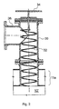
- Fig. 1 is a partial cross sectional schematic view of the assembly provided for feeding the powder or granular state material.
- the feeding assembly is preferably fitted on the lid 11 covering the upper part of a mixing space 10.
- the feeding of the powder or granular state material through the lid 11 is provided for by the pipe member 12, which enables feeding from above.
- the hydromechanical mixing apparatus has means for cleaning the inner wall of the inlet pipe member 12.
- the means according to the invention comprises a cleaning member 14, which can be moved bidirectionally in parallel with the feeding direction of the powder or granular state material along the inner wall of the inlet pipe member 12, as well as an actuating member 16 provided for displacing the cleaning member 14.
- the cleaning member 14 is formed as a pipe insert 14, which is fitted into the inlet pipe member 12, and the outer wall of the said pipe insert 14 is spaced apart from the inner wall of the pipe member 12. The appropriate spacing is ensured by sliding protrusions provided on the outer wall of the pipe insert 14 as shown in the figure.
- the at least one actuating member 16 is connected to the end of the pipe insert 14 protruding from the inlet pipe member 12.
- a flange 18 is connected to an upper edge of the pipe insert 14. With equal spacing around the periphery of the flange 18, several - in the example three - work cylinder pistons are connected thereto as actuating members.
- a pipeline or hopper 20 feeding the powder or granular state material - for example dry ash or flyash - from above is inserted into the pipe insert 14.
- a compensating cover 22 is provided for preventing dusting between the pipeline 20 and pipe insert 14 and pipe insert 14 and pipe member 12, respectively. Moving in a bellows fashion, the compensating cover 22 makes sure that the pipe insert 14 can be moved in two directions, maintaining the vacuum eventually needed in the mixing apparatus.
- a buffer made of fabric can be applied.
- the compensating cover has a thermal resistance of around 180°C and has a coating for facilitating sliding and cleaning on their inner surface.
- flushing air can be introduced into the mixing apparatus by means of an air inlet 24.
- a cleaning edge facilitating the removal of deposit is preferably provided on the bottom edge of the pipe insert 14.
- the cleaning edge is formed by conical milling of the inner wall of the pipe insert 14.
- a smudge-like deposit is generated during agitation, which can be removed by moving the pipe insert 14 cyclically up and down.
- the cleaning process may eventually be supplemented by cyclically introducing compressed air, where the air is blown in preferably in a tangential manner.
- the pipe member 12 and the cleaning member 14 are preferably made from stainless steel to make sure that the deposits can be easily slid and removed from the surfaces.
- Fig. 2 is a partial cross sectional view of the air outlet assembly of the mixing apparatus fitted with a cleaning means as shown in Fig. 1 .
- a pipe head 30 which is preferably fitted on the pipe stub located in the lid 11 a which covers the mixing space 10' from above.
- the pipe head 30 also has a means for cleaning its inner wall.
- this means includes a pipe head cleaner 32 made from spiral flat steel and an actuating member 34 - preferably a handle - connected to the pipe head cleaner 32 and protruding in a sealed manner from the pipe head 30.
- the pipe head 30 is arranged with a substantially vertical axis, and a discharging pipeline 36 is laterally connected thereto.
- the sludge consisting of the dust and thick slurry drops deposited in the pipe head 30 is removed by the pipe head cleaner 32.
- the vacuum can be maintained continuously in the mixing reservoir, while avoiding a sludge deposit.
- Both the pipe to be cleaned and the cleaner may be made of stainless steel to facilitate cleaning.
- the pipe head cleaner 32 for the air extraction of the mixing reservoir is movably affixed to the closing lid of the pipe head 30. By removing the lid, the pipe head cleaner 32 can be taken out for maintenance.
- FIG. 3 A schematic view of a further technological arrangement in association with the assembly of Fig. 2 is shown in Fig. 3 .
- the discharging pipeline 36 is connected to the dust separator 40 preferably via the safety air inlet valve 38.
- the dust separator 40 may also be preferably a bag type powder filter.
- the safety air inlet valve 38 also called the draught interrupter, protects the dust separator 40 and prevents the generation of an undesirably strong vacuum.
- the dust is delivered to the scrubber 44, where it is mixed into a dust slurry with water introduced through the scrubber water intake 46.
- the dust scrubber 44 may be made of carbon steel plate and is provided with appropriate surface protection. Depending on the dust to be treated, the dust slurry can have an alkaline or acidic reaction.
- the powder slurry is returned to the mixing space 10' via the powder slurry line 48.
- the return path can lead preferably via the pipe head 30.
- the required exhaustion for the dust separator 40 is provided by a fan 42 discharging the clean air through the air outlet 43 into the environment.
- the following objectives are achieved by discharging the air: vacuum is created in the mixing apparatus during operation, the air introduced into the mixing apparatus is quickly removed, any carbonation as a result of the CO 2 content of the air is prevented, and furthermore the slurry generated as a result of the agitation is free of bubbles.
- the hydromechanical mixing apparatus has means for cleaning the feeding member to prevent a deposit of the powder or granular state material, and preferably means for cleaning the air outlet.
- the mixing apparatus according to the invention may have a single mixing space when the two types of cleaning means shown are provided for cleaning the openings of the same mixing space.
- the invention is used in an apparatus having several mixing spaces, in which case the means designed to clean the inlet pipe member is preferably connected to a so-called premixing apparatus subassembly, and the means designed for cleaning the air outlet is connected to a main mixing space.
- the cleaning means also depicted in the figures may be constructed in other ways as well.
- an appropriately designed air injection may also be applied.
Landscapes
- Chemical & Material Sciences (AREA)
- Chemical Kinetics & Catalysis (AREA)
- Dispersion Chemistry (AREA)
- Engineering & Computer Science (AREA)
- Mechanical Engineering (AREA)
- Accessories For Mixers (AREA)
- Excavating Of Shafts Or Tunnels (AREA)
- Lubricants (AREA)
Abstract
Description
- The invention relates to a hydromechanical mixing apparatus for producing a mixture of powder or granular state material and liquid.
- In industry, it is frequently necessary to produce a mixture consisting of powder or granular state material and liquid. Such an application is the producing of a mixture - a so-called thick slurry - consisting of a solid phase combustion residue and water generated in a coal or oil-fired power station.
- The hydromechanical mixing apparatuses utilise the kinetic energy of flows generated gravitationally and/or by pressure. In the case of gravitational flows, the mixing of liquid and solid phases is carried out in the gravitation space by means of baffle elements installed in a fixed way in the gravitation space, while in the case of applying pressure generated flows, the energy required for agitation is created by the pumping of the liquid. By way of example, Hungarian patent No.
172 922 DE 26 02 858 A1 , which discloses an apparatus in accordance with the preamble of claim 1, describe a gravitational hydromechanical mixing apparatus, known by those skilled in the art as 'hydromix', and used for producing thick slurry. - It is a general characteristic of well-known hydromechanical mixing apparatuses that they have at least one mixing space into which a hopper member feeds from above the powder or granular state material. On the inner wall of the feeding hopper member, a slurry-type deposit is inevitably generated during agitation. This deposit on the one hand prevents the regulated intake of an appropriate material volume and on the other reduces the efficiency of agitation. A further risk related to the deposit is that it may even block the whole cross section of the hopper member, and by solidifying there, it may hinder the technological process. A further risk is represented by the fact that the deposit may collapse under the weight of powder or granular state material arriving from above, which may cause impulsive or, as the case may be, destructive damage of the structures in the mixing space.
- A further disadvantage of the prior art mixing apparatuses is that the pipe member or pipe head generally fitted on the top of the mixing tank and designed to extract the gases and/or air from the mixing space is also prone to being blocked. pipe cleaning device is described in
WO 2005/049240 . - The object of the invention is to create a hydromechanical mixing apparatus for producing a mixture of powder or granular state material and liquid, in which the disadvantages of prior art solutions are eliminated. A further objective is the creation of a mixing apparatus which has a means designed to clean the feeding mechanism. A further objective is the creation of such a mixing apparatus which enables the efficient removal of deposits in members for the feeding of the material and also in those applied for extracting the air.
- The invention thus relates to a hydromechanical mixing apparatus for producing a mixture of powder or granular state material and liquid. The apparatus has at least one mixing space and an inlet pipe member for feeding the powder or granular state material from above into the mixing space. The apparatus is characterised by comprising means for cleaning an inner wall of the inlet pipe member. Said means comprise:
- a cleaning member bidirectionally movable in parallel with the inlet direction, along the inner wall of the inlet pipe member, said cleaning member being a pipe insert inserted into the inlet pipe member, wherein the outer wall of the pipe insert is spaced apart from the inner wall of the pipe member, and
- an actuating member for moving the cleaning member, the actuating member being connected to the pipe insert's end protruding from the inlet pipe member.
By means of the pipe insert according to the invention, the removal of the deposit created on the inner wall of the inlet pipe member can be carried out very advantageously. - A preferred embodiment is characterised in that a flange is connected to an upper edge of the pipe insert and a plurality of bidirectionally movable work cylinder pistons are connected to the flange arranged with equal spacing around the periphery. Preferably, a pipeline feeding the powder or granular state material is inserted from above into the pipe insert and compensating cover is provided between the pipeline and the pipe insert and between the pipe insert and the pipe member, respectively, for preventing dusting and flexibly allowing the movement of the pipe insert. As a result of the beneficial movement and covering, the solution according to the invention can be implemented very simply and efficiently. Preferably, at a bottom edge of the pipe insert a cleaning edge is provided for facilitating cleaning.
- A particularly preferred embodiment is characterised in that it comprises a pipe head for discharging the gaseous materials therefrom, and the pipe head also comprises means for cleaning its inner wall. The means for cleaning the inner wall of the pipe head comprises a pipe head cleaner made of spiral fiat steel, and an actuating member - preferably a handle - protruding in a sealed manner from the pipe head. Thus, the pipe head cleaner according to the invention can be operated manually, because the dust slurry blocking the air outlet is a relatively rare occurrence as shown by experience. Therefore, the preferred embodiment outlined is the most cost efficient way to clean the inner wall of the pipe head provided for discharging air.
- The pipe head is preferably arranged with a substantially vertical axis, and a discharging pipeline is laterally connected thereto. The discharging pipeline is connected to a dust separator preferably via a safety air inlet valve and the separated dust is returned from the dust separator to the mixing space, preferably via the pipe head, in the form of dust slurry.
- The invention will hereinafter be described by way of preferred exemplary embodiments with reference to the drawings, where
-
Fig. 1 is a partial cross sectional view of the assembly provided for the feeding of the powder or granular state material with the cleaning means according to the invention, -
Fig. 2 is a partial cross sectional view of the air outlet assembly comprising a cleaning means for the mixing apparatus shown inFig. 1 , and -
Fig. 3 is a schematic view of a further technological arrangement associated with the assembly shown inFig. 2 . -
Fig. 1 is a partial cross sectional schematic view of the assembly provided for feeding the powder or granular state material. The feeding assembly is preferably fitted on thelid 11 covering the upper part of amixing space 10. The feeding of the powder or granular state material through thelid 11 is provided for by thepipe member 12, which enables feeding from above. - The hydromechanical mixing apparatus according to the invention has means for cleaning the inner wall of the
inlet pipe member 12. The means according to the invention comprises acleaning member 14, which can be moved bidirectionally in parallel with the feeding direction of the powder or granular state material along the inner wall of theinlet pipe member 12, as well as an actuatingmember 16 provided for displacing thecleaning member 14. - According to the preferred embodiment shown in the figure, the
cleaning member 14 is formed as apipe insert 14, which is fitted into theinlet pipe member 12, and the outer wall of the saidpipe insert 14 is spaced apart from the inner wall of thepipe member 12. The appropriate spacing is ensured by sliding protrusions provided on the outer wall of thepipe insert 14 as shown in the figure. The at least one actuatingmember 16 is connected to the end of the pipe insert 14 protruding from theinlet pipe member 12. - According to the depicted exemplary embodiment, a
flange 18 is connected to an upper edge of thepipe insert 14. With equal spacing around the periphery of theflange 18, several - in the example three - work cylinder pistons are connected thereto as actuating members. - A pipeline or hopper 20 feeding the powder or granular state material - for example dry ash or flyash - from above is inserted into the
pipe insert 14. A compensatingcover 22 is provided for preventing dusting between thepipeline 20 andpipe insert 14 andpipe insert 14 andpipe member 12, respectively. Moving in a bellows fashion, thecompensating cover 22 makes sure that thepipe insert 14 can be moved in two directions, maintaining the vacuum eventually needed in the mixing apparatus. Preferably, a buffer made of fabric can be applied. Preferably, the compensating cover has a thermal resistance of around 180°C and has a coating for facilitating sliding and cleaning on their inner surface. - In the embodiment shown by way of example, flushing air can be introduced into the mixing apparatus by means of an
air inlet 24. - On the bottom edge of the pipe insert 14, a cleaning edge facilitating the removal of deposit is preferably provided. Preferably, the cleaning edge is formed by conical milling of the inner wall of the pipe insert 14.
- On the inner surface of the
pipe member 12, a smudge-like deposit is generated during agitation, which can be removed by moving the pipe insert 14 cyclically up and down. The cleaning process may eventually be supplemented by cyclically introducing compressed air, where the air is blown in preferably in a tangential manner. - The
pipe member 12 and thecleaning member 14 are preferably made from stainless steel to make sure that the deposits can be easily slid and removed from the surfaces. -
Fig. 2 is a partial cross sectional view of the air outlet assembly of the mixing apparatus fitted with a cleaning means as shown inFig. 1 . For extracting the gaseous materials from the mixing space 10', there is apipe head 30 which is preferably fitted on the pipe stub located in thelid 11 a which covers the mixing space 10' from above. In a preferred embodiment, thepipe head 30 also has a means for cleaning its inner wall. Preferably, this means includes a pipe head cleaner 32 made from spiral flat steel and an actuating member 34 - preferably a handle - connected to the pipe head cleaner 32 and protruding in a sealed manner from thepipe head 30. Thepipe head 30 is arranged with a substantially vertical axis, and a dischargingpipeline 36 is laterally connected thereto. - The dusty air comprising thick slurry drops exits the mixing reservoir through the
pipe head 30. The sludge consisting of the dust and thick slurry drops deposited in thepipe head 30 is removed by thepipe head cleaner 32. By the repeated operation of the pipe head cleaner 32, the vacuum can be maintained continuously in the mixing reservoir, while avoiding a sludge deposit. Both the pipe to be cleaned and the cleaner may be made of stainless steel to facilitate cleaning. The pipe head cleaner 32 for the air extraction of the mixing reservoir is movably affixed to the closing lid of thepipe head 30. By removing the lid, the pipe head cleaner 32 can be taken out for maintenance. - A schematic view of a further technological arrangement in association with the assembly of
Fig. 2 is shown inFig. 3 . As shown in the figure, the dischargingpipeline 36 is connected to thedust separator 40 preferably via the safetyair inlet valve 38. Thedust separator 40 may also be preferably a bag type powder filter. In case thepipe head 30 is blocked as a result of a breakdown of the pipe head cleaner 32, the vacuum increases in thedust separator 40. The safetyair inlet valve 38, also called the draught interrupter, protects thedust separator 40 and prevents the generation of an undesirably strong vacuum. - From the
dust separator 40, the dust is delivered to thescrubber 44, where it is mixed into a dust slurry with water introduced through thescrubber water intake 46. Thedust scrubber 44 may be made of carbon steel plate and is provided with appropriate surface protection. Depending on the dust to be treated, the dust slurry can have an alkaline or acidic reaction. The powder slurry is returned to the mixing space 10' via thepowder slurry line 48. The return path can lead preferably via thepipe head 30. The required exhaustion for thedust separator 40 is provided by afan 42 discharging the clean air through theair outlet 43 into the environment. - The following objectives are achieved by discharging the air: vacuum is created in the mixing apparatus during operation, the air introduced into the mixing apparatus is quickly removed, any carbonation as a result of the CO2 content of the air is prevented, and furthermore the slurry generated as a result of the agitation is free of bubbles.
- Consequently, the hydromechanical mixing apparatus according to the invention has means for cleaning the feeding member to prevent a deposit of the powder or granular state material, and preferably means for cleaning the air outlet. Through these measures, the hydromechanical mixing apparatus will work continuously, and the mixing process will not be interrupted by disadvantageous effects caused by the deposits.
- It is to be appreciated that the invention is not limited to the preferred embodiments shown by way of example in the figures, but further modifications are possible within the scope of protection defined by the claims. The mixing apparatus according to the invention may have a single mixing space when the two types of cleaning means shown are provided for cleaning the openings of the same mixing space. At the same time it is also conceivable that the invention is used in an apparatus having several mixing spaces, in which case the means designed to clean the inlet pipe member is preferably connected to a so-called premixing apparatus subassembly, and the means designed for cleaning the air outlet is connected to a main mixing space.
- The cleaning means also depicted in the figures may be constructed in other ways as well. For improving the efficiency of cleaning, preferably and by way of example an appropriately designed air injection may also be applied.
- It is to be appreciated that the system and procedure according to the invention is not limited to the embodiments and methods described in detail, but further modifications and changes are possible within the scope of protection defined by the claims.
Claims (8)
- A hydromechanical mixing apparatus for producing a mixture of powder or granular state material and liquid, having at least one mixing space (10) and an inlet pipe member (12) for feeding the powder or granular state material from above into the mixing space, characterised in that it comprises means for cleaning an inner wall of the inlet pipe member (12), said means comprising:- a cleaning member (14) bidirectionally movable in parallel with the inlet direction, along the inner wall of the inlet pipe member (12), said cleaning member (14) being a pipe insert (14) inserted into the inlet pipe member (12), wherein the outer wall of the pipe insert (14) is spaced apart from the inner wall of the pipe member (12), and- an actuating member (16) for moving the cleaning member (14), the actuating member (16) being connected to the pipe insert's (14) end protruding from the inlet pipe member (12).
- The mixing apparatus according to claim 1, characterised in that a flange (18) is connected to an upper edge of the pipe insert (14) and a plurality of bidirectionally movable work cylinder pistons are connected to the flange (18) arranged with equal spacing around the periphery.
- The mixing apparatus according to claim 2, characterised in that a pipeline (20) feeding the powder or granular state material is inserted from above into the pipe insert (14) and a compensating cover (22) is provided between the pipeline (20) and the pipe insert (14) and between the pipe insert (14) and the pipe member (12), respectively, for preventing dusting and flexibly allowing the movement of the pipe insert (14).
- The mixing apparatus according to claim 1, characterised in that at a bottom edge of the pipe insert (14) a cleaning edge is provided for facilitating cleaning.
- The mixing apparatus according to any of the claims 1 to 4, characterised by comprising a pipe head (30) for discharging gaseous materials therefrom, and the pipe head (30) also comprises means for cleaning its inner wall, wherein said pipe head (30) is preferably fitted on a pipe stub located in a lid (11a) covering the mixing space (10') from above.
- The mixing apparatus according to claim 5, characterised in that the means for cleaning the inner wall of the pipe head (30) comprises a pipe head cleaner (32) made of spiral flat steel, and an actuating member (34) - preferably a handle - protruding in a sealed manner from the pipe head (30).
- The mixing apparatus according to claim 5, characterised in that the pipe head (30) is arranged with a substantially vertical axis, and a discharging pipeline,(36) is laterally connected thereto.
- The mixing apparatus according to claim 7, characterised in that the discharging pipeline (36) is connected to a dust separator (40) preferably via a safety air inlet valve (38) and the separated dust is returned from the dust separator (40) to the mixing space (10'), preferably via the pipe head (30), in the form of dust slurry.
Applications Claiming Priority (2)
| Application Number | Priority Date | Filing Date | Title |
|---|---|---|---|
| HU0600492A HU229615B1 (en) | 2006-06-14 | 2006-06-14 | Hydro-mechanical mixer |
| PCT/HU2007/000051 WO2007144675A1 (en) | 2006-06-14 | 2007-06-12 | Hydromechanical mixing apparatus |
Publications (2)
| Publication Number | Publication Date |
|---|---|
| EP2035127A1 EP2035127A1 (en) | 2009-03-18 |
| EP2035127B1 true EP2035127B1 (en) | 2010-09-22 |
Family
ID=89986844
Family Applications (1)
| Application Number | Title | Priority Date | Filing Date |
|---|---|---|---|
| EP07733868A Active EP2035127B1 (en) | 2006-06-14 | 2007-06-12 | Hydromechanical mixing apparatus |
Country Status (6)
| Country | Link |
|---|---|
| EP (1) | EP2035127B1 (en) |
| CN (1) | CN101466458B (en) |
| AT (1) | ATE482017T1 (en) |
| DE (1) | DE602007009389D1 (en) |
| HU (1) | HU229615B1 (en) |
| WO (1) | WO2007144675A1 (en) |
Family Cites Families (5)
| Publication number | Priority date | Publication date | Assignee | Title |
|---|---|---|---|---|
| HU172922B (en) * | 1975-02-05 | 1979-01-28 | Melyepitesi Tervezo Vallalat | Apparatus for mixing solid, granular and/or dustlike materials into fluid particularly for producing sludge at pipeline carrying |
| FR2670131B1 (en) * | 1990-12-11 | 1993-08-13 | Cellier | INSTALLATION FOR FORMULATING LIQUID-BASED MIXTURES WITH A SCRAPED DOSING UNIT AND RELATED FORMULATION METHOD. |
| DE10145274A1 (en) * | 2001-09-14 | 2003-04-10 | Wilhelm Pier | Mechanical removal of petroleum coke deposits from branch pipes in acetylene production apparatus uses boring machine sealed on to branch which can clear deposits during production |
| ITTO20020984A1 (en) * | 2002-11-13 | 2003-02-11 | Termoelettronica S P A | SYSTEM FOR DOSING AND SLIDING FOR SILO POWDERS. |
| GB0326707D0 (en) * | 2003-11-17 | 2003-12-17 | Boc Group Plc | Exhaust gas treatment |
-
2006
- 2006-06-14 HU HU0600492A patent/HU229615B1/en not_active IP Right Cessation
-
2007
- 2007-06-12 CN CN2007800218160A patent/CN101466458B/en not_active Expired - Fee Related
- 2007-06-12 WO PCT/HU2007/000051 patent/WO2007144675A1/en not_active Ceased
- 2007-06-12 AT AT07733868T patent/ATE482017T1/en not_active IP Right Cessation
- 2007-06-12 EP EP07733868A patent/EP2035127B1/en active Active
- 2007-06-12 DE DE602007009389T patent/DE602007009389D1/en active Active
Also Published As
| Publication number | Publication date |
|---|---|
| HU229615B1 (en) | 2014-03-28 |
| EP2035127A1 (en) | 2009-03-18 |
| DE602007009389D1 (en) | 2010-11-04 |
| HU0600492D0 (en) | 2006-08-28 |
| WO2007144675A1 (en) | 2007-12-21 |
| CN101466458B (en) | 2011-08-31 |
| ATE482017T1 (en) | 2010-10-15 |
| CN101466458A (en) | 2009-06-24 |
| HUP0600492A2 (en) | 2010-01-28 |
Similar Documents
| Publication | Publication Date | Title |
|---|---|---|
| CA1037882A (en) | Method of removing finely divided solids from gas | |
| CN1993162B (en) | Retort heating apparatus and methods | |
| US4244715A (en) | Dust removal apparatus | |
| US9242203B2 (en) | Device and a method of cleaning an effluent gas from an aluminium production electrolytic cell | |
| US9126772B2 (en) | Apparatus and related method for the recovery and the pneumatic transportation of dust coming from a filtration system | |
| US8104645B2 (en) | Device for discharging granular material | |
| US20130259758A1 (en) | Filter device and filter method | |
| JP2000509737A (en) | Apparatus and method for separating and stripping fluid catalytic cracking particles from gaseous hydrocarbons | |
| JP5174852B2 (en) | Kernel separator, grain air conveying device, and grain air conveying method | |
| CN205127613U (en) | Wet type dust collection unit | |
| EP2035127A1 (en) | Hydromechanical mixing apparatus | |
| JP2009262065A (en) | Tank cleaning apparatus and cleaning method | |
| JPS5839735B2 (en) | Kuaatsu Sadunohopper | |
| CN208775487U (en) | A kind of lower hopper | |
| JP2797059B2 (en) | Blast equipment | |
| CN214182405U (en) | Material sedimentation and deslagging device | |
| RU2841401C1 (en) | Device for collection, recovery and temporary storage of abrasive medium during open shot blasting | |
| CN216945274U (en) | Material negative pressure conveying device | |
| CN218173910U (en) | Vacuum storage bin device | |
| US8617389B2 (en) | Device for filtering the liquid processing medium used in shaping operations performed by cutting | |
| CN212092215U (en) | High-temperature-resistant foam processing equipment | |
| EP3771517A1 (en) | Device adapted to the separation of shavings contained in a cutting fluid used in machine tools | |
| CN212798785U (en) | A scraper dust removal device | |
| SE434347B (en) | Method of decomposing a liquid medium and arrangement for it | |
| CN211462556U (en) | an integrated separator |
Legal Events
| Date | Code | Title | Description |
|---|---|---|---|
| PUAI | Public reference made under article 153(3) epc to a published international application that has entered the european phase |
Free format text: ORIGINAL CODE: 0009012 |
|
| 17P | Request for examination filed |
Effective date: 20090112 |
|
| AK | Designated contracting states |
Kind code of ref document: A1 Designated state(s): AT BE BG CH CY CZ DE DK EE ES FI FR GB GR HU IE IS IT LI LT LU LV MC MT NL PL PT RO SE SI SK TR |
|
| AX | Request for extension of the european patent |
Extension state: AL BA HR MK RS |
|
| GRAP | Despatch of communication of intention to grant a patent |
Free format text: ORIGINAL CODE: EPIDOSNIGR1 |
|
| GRAS | Grant fee paid |
Free format text: ORIGINAL CODE: EPIDOSNIGR3 |
|
| GRAA | (expected) grant |
Free format text: ORIGINAL CODE: 0009210 |
|
| AK | Designated contracting states |
Kind code of ref document: B1 Designated state(s): AT BE BG CH CY CZ DE DK EE ES FI FR GB GR HU IE IS IT LI LT LU LV MC MT NL PL PT RO SE SI SK TR |
|
| AX | Request for extension of the european patent |
Extension state: AL BA HR MK RS |
|
| REG | Reference to a national code |
Ref country code: GB Ref legal event code: FG4D |
|
| REG | Reference to a national code |
Ref country code: CH Ref legal event code: EP |
|
| REG | Reference to a national code |
Ref country code: IE Ref legal event code: FG4D |
|
| REF | Corresponds to: |
Ref document number: 602007009389 Country of ref document: DE Date of ref document: 20101104 Kind code of ref document: P |
|
| REG | Reference to a national code |
Ref country code: RO Ref legal event code: EPE |
|
| PG25 | Lapsed in a contracting state [announced via postgrant information from national office to epo] |
Ref country code: AT Free format text: LAPSE BECAUSE OF FAILURE TO SUBMIT A TRANSLATION OF THE DESCRIPTION OR TO PAY THE FEE WITHIN THE PRESCRIBED TIME-LIMIT Effective date: 20100922 Ref country code: LT Free format text: LAPSE BECAUSE OF FAILURE TO SUBMIT A TRANSLATION OF THE DESCRIPTION OR TO PAY THE FEE WITHIN THE PRESCRIBED TIME-LIMIT Effective date: 20100922 Ref country code: FI Free format text: LAPSE BECAUSE OF FAILURE TO SUBMIT A TRANSLATION OF THE DESCRIPTION OR TO PAY THE FEE WITHIN THE PRESCRIBED TIME-LIMIT Effective date: 20100922 |
|
| REG | Reference to a national code |
Ref country code: NL Ref legal event code: VDEP Effective date: 20100922 |
|
| LTIE | Lt: invalidation of european patent or patent extension |
Effective date: 20100922 |
|
| PG25 | Lapsed in a contracting state [announced via postgrant information from national office to epo] |
Ref country code: SI Free format text: LAPSE BECAUSE OF FAILURE TO SUBMIT A TRANSLATION OF THE DESCRIPTION OR TO PAY THE FEE WITHIN THE PRESCRIBED TIME-LIMIT Effective date: 20100922 Ref country code: PL Free format text: LAPSE BECAUSE OF FAILURE TO SUBMIT A TRANSLATION OF THE DESCRIPTION OR TO PAY THE FEE WITHIN THE PRESCRIBED TIME-LIMIT Effective date: 20100922 |
|
| PG25 | Lapsed in a contracting state [announced via postgrant information from national office to epo] |
Ref country code: LV Free format text: LAPSE BECAUSE OF FAILURE TO SUBMIT A TRANSLATION OF THE DESCRIPTION OR TO PAY THE FEE WITHIN THE PRESCRIBED TIME-LIMIT Effective date: 20100922 Ref country code: GR Free format text: LAPSE BECAUSE OF FAILURE TO SUBMIT A TRANSLATION OF THE DESCRIPTION OR TO PAY THE FEE WITHIN THE PRESCRIBED TIME-LIMIT Effective date: 20101223 Ref country code: SE Free format text: LAPSE BECAUSE OF FAILURE TO SUBMIT A TRANSLATION OF THE DESCRIPTION OR TO PAY THE FEE WITHIN THE PRESCRIBED TIME-LIMIT Effective date: 20100922 |
|
| PG25 | Lapsed in a contracting state [announced via postgrant information from national office to epo] |
Ref country code: CZ Free format text: LAPSE BECAUSE OF FAILURE TO SUBMIT A TRANSLATION OF THE DESCRIPTION OR TO PAY THE FEE WITHIN THE PRESCRIBED TIME-LIMIT Effective date: 20100922 Ref country code: PT Free format text: LAPSE BECAUSE OF FAILURE TO SUBMIT A TRANSLATION OF THE DESCRIPTION OR TO PAY THE FEE WITHIN THE PRESCRIBED TIME-LIMIT Effective date: 20110124 Ref country code: IT Free format text: LAPSE BECAUSE OF FAILURE TO SUBMIT A TRANSLATION OF THE DESCRIPTION OR TO PAY THE FEE WITHIN THE PRESCRIBED TIME-LIMIT Effective date: 20100922 Ref country code: IS Free format text: LAPSE BECAUSE OF FAILURE TO SUBMIT A TRANSLATION OF THE DESCRIPTION OR TO PAY THE FEE WITHIN THE PRESCRIBED TIME-LIMIT Effective date: 20110122 Ref country code: EE Free format text: LAPSE BECAUSE OF FAILURE TO SUBMIT A TRANSLATION OF THE DESCRIPTION OR TO PAY THE FEE WITHIN THE PRESCRIBED TIME-LIMIT Effective date: 20100922 Ref country code: SK Free format text: LAPSE BECAUSE OF FAILURE TO SUBMIT A TRANSLATION OF THE DESCRIPTION OR TO PAY THE FEE WITHIN THE PRESCRIBED TIME-LIMIT Effective date: 20100922 Ref country code: NL Free format text: LAPSE BECAUSE OF FAILURE TO SUBMIT A TRANSLATION OF THE DESCRIPTION OR TO PAY THE FEE WITHIN THE PRESCRIBED TIME-LIMIT Effective date: 20100922 |
|
| PG25 | Lapsed in a contracting state [announced via postgrant information from national office to epo] |
Ref country code: BE Free format text: LAPSE BECAUSE OF FAILURE TO SUBMIT A TRANSLATION OF THE DESCRIPTION OR TO PAY THE FEE WITHIN THE PRESCRIBED TIME-LIMIT Effective date: 20100922 |
|
| PG25 | Lapsed in a contracting state [announced via postgrant information from national office to epo] |
Ref country code: ES Free format text: LAPSE BECAUSE OF FAILURE TO SUBMIT A TRANSLATION OF THE DESCRIPTION OR TO PAY THE FEE WITHIN THE PRESCRIBED TIME-LIMIT Effective date: 20110102 |
|
| PLBE | No opposition filed within time limit |
Free format text: ORIGINAL CODE: 0009261 |
|
| STAA | Information on the status of an ep patent application or granted ep patent |
Free format text: STATUS: NO OPPOSITION FILED WITHIN TIME LIMIT |
|
| 26N | No opposition filed |
Effective date: 20110623 |
|
| PG25 | Lapsed in a contracting state [announced via postgrant information from national office to epo] |
Ref country code: DK Free format text: LAPSE BECAUSE OF FAILURE TO SUBMIT A TRANSLATION OF THE DESCRIPTION OR TO PAY THE FEE WITHIN THE PRESCRIBED TIME-LIMIT Effective date: 20100922 |
|
| REG | Reference to a national code |
Ref country code: DE Ref legal event code: R097 Ref document number: 602007009389 Country of ref document: DE Effective date: 20110623 |
|
| PG25 | Lapsed in a contracting state [announced via postgrant information from national office to epo] |
Ref country code: MT Free format text: LAPSE BECAUSE OF FAILURE TO SUBMIT A TRANSLATION OF THE DESCRIPTION OR TO PAY THE FEE WITHIN THE PRESCRIBED TIME-LIMIT Effective date: 20100922 |
|
| REG | Reference to a national code |
Ref country code: CH Ref legal event code: PL |
|
| GBPC | Gb: european patent ceased through non-payment of renewal fee |
Effective date: 20110612 |
|
| REG | Reference to a national code |
Ref country code: FR Ref legal event code: ST Effective date: 20120229 |
|
| REG | Reference to a national code |
Ref country code: IE Ref legal event code: MM4A |
|
| REG | Reference to a national code |
Ref country code: DE Ref legal event code: R119 Ref document number: 602007009389 Country of ref document: DE Effective date: 20120103 |
|
| PG25 | Lapsed in a contracting state [announced via postgrant information from national office to epo] |
Ref country code: LI Free format text: LAPSE BECAUSE OF NON-PAYMENT OF DUE FEES Effective date: 20110630 Ref country code: DE Free format text: LAPSE BECAUSE OF NON-PAYMENT OF DUE FEES Effective date: 20120103 Ref country code: IE Free format text: LAPSE BECAUSE OF NON-PAYMENT OF DUE FEES Effective date: 20110612 Ref country code: CH Free format text: LAPSE BECAUSE OF NON-PAYMENT OF DUE FEES Effective date: 20110630 Ref country code: FR Free format text: LAPSE BECAUSE OF NON-PAYMENT OF DUE FEES Effective date: 20110630 |
|
| PG25 | Lapsed in a contracting state [announced via postgrant information from national office to epo] |
Ref country code: GB Free format text: LAPSE BECAUSE OF NON-PAYMENT OF DUE FEES Effective date: 20110612 |
|
| PG25 | Lapsed in a contracting state [announced via postgrant information from national office to epo] |
Ref country code: MC Free format text: LAPSE BECAUSE OF NON-PAYMENT OF DUE FEES Effective date: 20110630 |
|
| PG25 | Lapsed in a contracting state [announced via postgrant information from national office to epo] |
Ref country code: CY Free format text: LAPSE BECAUSE OF FAILURE TO SUBMIT A TRANSLATION OF THE DESCRIPTION OR TO PAY THE FEE WITHIN THE PRESCRIBED TIME-LIMIT Effective date: 20100922 Ref country code: LU Free format text: LAPSE BECAUSE OF NON-PAYMENT OF DUE FEES Effective date: 20110612 |
|
| PG25 | Lapsed in a contracting state [announced via postgrant information from national office to epo] |
Ref country code: BG Free format text: LAPSE BECAUSE OF FAILURE TO SUBMIT A TRANSLATION OF THE DESCRIPTION OR TO PAY THE FEE WITHIN THE PRESCRIBED TIME-LIMIT Effective date: 20101222 |
|
| PG25 | Lapsed in a contracting state [announced via postgrant information from national office to epo] |
Ref country code: HU Free format text: LAPSE BECAUSE OF FAILURE TO SUBMIT A TRANSLATION OF THE DESCRIPTION OR TO PAY THE FEE WITHIN THE PRESCRIBED TIME-LIMIT Effective date: 20100922 |
|
| PGFP | Annual fee paid to national office [announced via postgrant information from national office to epo] |
Ref country code: TR Payment date: 20160520 Year of fee payment: 10 Ref country code: RO Payment date: 20160513 Year of fee payment: 10 |
|
| PG25 | Lapsed in a contracting state [announced via postgrant information from national office to epo] |
Ref country code: RO Free format text: LAPSE BECAUSE OF NON-PAYMENT OF DUE FEES Effective date: 20170612 |
|
| PG25 | Lapsed in a contracting state [announced via postgrant information from national office to epo] |
Ref country code: TR Free format text: LAPSE BECAUSE OF NON-PAYMENT OF DUE FEES Effective date: 20170612 |