EP2034578A1 - Mounting frame for application modules - Google Patents
Mounting frame for application modules Download PDFInfo
- Publication number
- EP2034578A1 EP2034578A1 EP07115630A EP07115630A EP2034578A1 EP 2034578 A1 EP2034578 A1 EP 2034578A1 EP 07115630 A EP07115630 A EP 07115630A EP 07115630 A EP07115630 A EP 07115630A EP 2034578 A1 EP2034578 A1 EP 2034578A1
- Authority
- EP
- European Patent Office
- Prior art keywords
- mounting frame
- slot
- supply unit
- width
- medical supply
- Prior art date
- Legal status (The legal status is an assumption and is not a legal conclusion. Google has not performed a legal analysis and makes no representation as to the accuracy of the status listed.)
- Granted
Links
Images




Classifications
-
- H—ELECTRICITY
- H02—GENERATION; CONVERSION OR DISTRIBUTION OF ELECTRIC POWER
- H02G—INSTALLATION OF ELECTRIC CABLES OR LINES, OR OF COMBINED OPTICAL AND ELECTRIC CABLES OR LINES
- H02G3/00—Installations of electric cables or lines or protective tubing therefor in or on buildings, equivalent structures or vehicles
- H02G3/02—Details
- H02G3/08—Distribution boxes; Connection or junction boxes
- H02G3/12—Distribution boxes; Connection or junction boxes for flush mounting
- H02G3/128—Distribution boxes; Connection or junction boxes for flush mounting in plinths, channels, raceways or similar
Definitions
- the present invention concerns a mounting frame for application modules such as electrical modules, which can be a power socket-outlet for a plug of any electrical device, a switch, a socket-outlet for data connection, etc.
- application modules can also be of other kind, such as for example gas connections or luminaires.
- the mounting frame is suitable and extremely useful to be applied in a so called medical supply unit, usually provided above or near a hospital bed.
- Such a medical supply unit usually installed against the wall above or near the head side of the hospital bed, can be provided with several functions, from compressed air to data connections.
- Such medical supply units are for example known from and commercialized by Trilux.
- the front side of such a medical supply unit usually consists of a single aluminum profile which for maintenance reasons is preferably flat at the side meant to be positioned at the outside of the medical supply unit, while at the opposite side, it is provided of elongate ribs which serve to fit the profile into the medical supply unit and for installing the mounting frames for the application modules, hereby avoiding the use of screws or any other irregularities at the front side.
- Such a medical supply unit profile is further provided with openings allowing the application module to reach from the back side to the front side.
- the known mounting frames for such application modules are generally square shaped and flat and can be slit between two opposing L-shaped ribs provided on the back of the aluminum medical supply unit profile.
- a disadvantage of such known mounting frames is that they require a lot of preparation and a final mounting plan of the complete medical supply unit. Indeed, sliding in the mounting frames requires a detailed vision on the end product and it is time consuming.
- An alternative known mounting frame as described in EP0.837.535 is provided with resilient portions which allow to clips the mounting frames into the medical supply unit profile.
- resiliently applied mounting frames can not easily be displaced after their fixation and that they are generally expensive to produce and furthermore fragile. Moreover, such a mounting frame with resilient portions requires accurate mounting because in case of the opposite, the mounting frame may be pushed out of its weakly secured position. If this happens after the medical supply unit has been taken into use, consequences are worst as in that case the medical supply unit would require a complete disassembly.
- the current invention aims to offer a solution for the above-mentioned and other disadvantages.
- the invention concerns a mounting frame for an application module which has a generally rectangular shape whereof at least one corner is rounded to such an extent that the distance between the at least one rounded corner and the diagonally opposing corner is of generally the same magnitude as the length of the generally rectangular frame, i.e. the largest distance between two opposing flanges of the frame.
- Such a mounting frame allows to be inserted between the two L-shaped ribs provided on the back side of a medical supply unit profile, which form a T-profile-shaped longitudinal slot which is open towards the back side of the medical supply unit profile and serves for holding and for retaining mounting frames for the application modules.
- the frame of which the width is smaller than the distance between the free extremities of the L-shaped ribs can, when suitably held, easily be inserted through the outer partial slot of relatively small dimensions into an inner partial slot of larger dimensions and can be rotated there from a first position into a second position, allowing fixation in its final position prior to the mounting of an application module.
- the width of the frame should be smaller than the width of the outer slot, while the length of the frame should be smaller than the width of the inner slot.
- At least one corner should be rounded to such an extent that the distance between that rounded corner and the diagonally opposing corner is smaller than the width of the inner slot.
- the present invention is also related to an assembly of a medical supply unit profile and a mounting frame for an application module, where the medical supply unit profile is provided of a T-profile-shaped longitudinal slot, comprising an outer partial slot of smaller width Wo and an inner partial slot of larger width Wi, and where the mounting frame for an application module has a generally rectangular shape, having an overall width W and an overall length L, the frame of which the width W is smaller than the width Wo of the outer partial slot such that the mounting frame can be inserted into the T-profile-shaped slot, and the frame of which the length L is smaller than the width Wi of the inner partial slot, and the frame whereof at least one corner is rounded to such an extent that the distance A between the at least one rounded corner and the diagonally opposing corner is smaller than the width Wi of the inner partial slot, such that the frame, once inserted through the outer slot, can be rotated there from a first position into a second position wherein the frame rests in the slot, allowing fixation of the mounting frame in its final position in the medical supply unit profile prior to
- the application module can be provided through the central hole in the mounting frame and through the opening in the medical supply unit profile, which allows the application module to reach from the back side to the front side of the medical supply unit profile.
- the application of the application module also fixes the mounting frame in its position, more in particular thanks to the corresponding shape and the cooperating edges of the protruding portion of the application module, on the one hand, and of the opening in the medical supply unit profile, on the other hand.
- the mounting frame is provided with resilient portions, which assure a secure fixing of the mounting frame once it is turned in its position in which the application module will be applied.
- Such resilient portions prevent the sliding and/or the rotation of the mounting frame in the slot already prior to the application of the application module. Such resilient portions are in particular helpful where the assembly of the mounting frames and the application modules is performed in conditions where the medical supply unit profile is not always positioned horizontally.
- more than one corner can be rounded. In case where two opposing corners are rounded, less rounding is required to enable the desired freedom to rotate.
- Figure 1 represents a preferred embodiment of a mounting frame 1 for application modules according to the invention, which has a generally rectangular shape with length L and width W.
- first corner 2 and diagonally opposed second corner 3 are rounded to such an extent that the distance A between these rounded corners is generally equal to the length L of the mounting frame 1.
- figure 2 an assembly of a medical supply unit profile 4 and the mounting frame 1 of figure 1 is shown.
- the medical supply unit profile 4 is provided on the back side with two L-shaped ribs 5 and 6 of which the respective free extremities 7 and 8 are oriented towards each other.
- the two said ribs 5 and 6 form a T-profile-shaped longitudinal slot 9, comprising an outer partial slot 10 of smaller width Wo and an inner partial slot 11 of larger width Wi.
- the width W of the mounting frame 1 is smaller than the width Wo of the outer partial slot 10 such that the mounting frame 1 can be inserted into the T-profile-shaped slot 9.
- the length L of the mounting frame 1 is smaller than the width Wi of the inner partial slot 11.
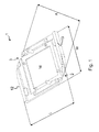
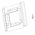
- the distance A between the rounded corners 2 and 3 and the shape of these corners is such that the frame 1, once inserted through the outer slot 10, can be rotated there from a first position into a second position wherein the frame 1 rests in the slot 9, as shown in figures 3 and 4 .
- the distance A between the two corners 2 and 3 according to all possible orientations is smaller than the width Wi of the inner partial slot 11.
- the thickness of the mounting frame 1 is greater along the shorter borderlines 12 and 13, more in particular a fraction less than the available height in the inner slot 11, i.e. between the free extremities 7 and 8 of the L-shaped ribs 5 and 6 on the one hand, and the base plate 14 of the medical supply unit profile 4 on the other hand.
- the central portion of the mounting frame 1 is provided of a square opening 16, and also the base plate 14 of the medical supply unit profile 4 is provided of a series of corresponding square openings 17.
- a square shaped protruding portion 18 of the electric module 15 is provided through the square opening 16 in the mounting frame 1 and also through the square opening 17 in the base plate 14 of the medical supply unit profile 4, which openings 16 and 17 ought to be situated in line of each other.
- the front side 19 of the square shaped protruding portion 18 of the electric module 15 is meant to be in line with the front side of the medical supply unit profile 4, which facilitates the cleaning and which avoids the accumulation of dirt.
- the shape and the measurements of the protruding portion 18 of the electric module 15 correspond, taking into account an appropriate tolerance, with the shape and the measurements of the openings 17 in the base plate 14 of the medical supply unit profile 4.
- mounting frame 1 can optionally be provided with resilient portions, for example near one or both of the transitions of the rounded corners 2 and 3 and the flat shorter borderlines 12 and 13.
- protruding portion of the application module and the corresponding openings in the mounting frame and base plate of the profile generally can be of any shape, for instance rectangular, square, triangular, circular, oval, etc., depending on the application, design aspects, esthetical preferences, etc.
- Such resilient portions for example in the form of a stretched piece made of the same material of which the mounting frame 1 is made, or as a compact element made of a more elastic material, can be deformed if a certain force is performed in order to allow rotation of the mounting frame 1 in the desired position.
- the resilient portions apart from preventing undesired rotation, might be shaped such that they also prevent undesired sliding of the mounting frame 1, which further facilitates the mounting of the application modules.
Landscapes
- Engineering & Computer Science (AREA)
- Architecture (AREA)
- Civil Engineering (AREA)
- Structural Engineering (AREA)
- Accommodation For Nursing Or Treatment Tables (AREA)
- Communication Control (AREA)
- Mutual Connection Of Rods And Tubes (AREA)
Abstract
Description
- The present invention concerns a mounting frame for application modules such as electrical modules, which can be a power socket-outlet for a plug of any electrical device, a switch, a socket-outlet for data connection, etc. The application modules can also be of other kind, such as for example gas connections or luminaires.
- More in particular, the mounting frame is suitable and extremely useful to be applied in a so called medical supply unit, usually provided above or near a hospital bed.
- Such a medical supply unit, usually installed against the wall above or near the head side of the hospital bed, can be provided with several functions, from compressed air to data connections. Such medical supply units are for example known from and commercialized by Trilux.
- The front side of such a medical supply unit usually consists of a single aluminum profile which for maintenance reasons is preferably flat at the side meant to be positioned at the outside of the medical supply unit, while at the opposite side, it is provided of elongate ribs which serve to fit the profile into the medical supply unit and for installing the mounting frames for the application modules, hereby avoiding the use of screws or any other irregularities at the front side.
- Such a medical supply unit profile is further provided with openings allowing the application module to reach from the back side to the front side. The known mounting frames for such application modules are generally square shaped and flat and can be slit between two opposing L-shaped ribs provided on the back of the aluminum medical supply unit profile.
- A disadvantage of such known mounting frames is that they require a lot of preparation and a final mounting plan of the complete medical supply unit. Indeed, sliding in the mounting frames requires a detailed vision on the end product and it is time consuming.
- An alternative known mounting frame as described in
EP0.837.535 is provided with resilient portions which allow to clips the mounting frames into the medical supply unit profile. - It is though known that resiliently applied mounting frames can not easily be displaced after their fixation and that they are generally expensive to produce and furthermore fragile. Moreover, such a mounting frame with resilient portions requires accurate mounting because in case of the opposite, the mounting frame may be pushed out of its weakly secured position. If this happens after the medical supply unit has been taken into use, consequences are worst as in that case the medical supply unit would require a complete disassembly.
- The current invention aims to offer a solution for the above-mentioned and other disadvantages.
- To this end the invention concerns a mounting frame for an application module which has a generally rectangular shape whereof at least one corner is rounded to such an extent that the distance between the at least one rounded corner and the diagonally opposing corner is of generally the same magnitude as the length of the generally rectangular frame, i.e. the largest distance between two opposing flanges of the frame.
- Such a mounting frame allows to be inserted between the two L-shaped ribs provided on the back side of a medical supply unit profile, which form a T-profile-shaped longitudinal slot which is open towards the back side of the medical supply unit profile and serves for holding and for retaining mounting frames for the application modules. Indeed, the frame of which the width is smaller than the distance between the free extremities of the L-shaped ribs can, when suitably held, easily be inserted through the outer partial slot of relatively small dimensions into an inner partial slot of larger dimensions and can be rotated there from a first position into a second position, allowing fixation in its final position prior to the mounting of an application module.
- It is clear that both the distance between ribs and the dimensions of the ribs, in other words the dimensions of the inner partial slot and the outer partial slot, determine the dimensions of the frame.
- Generally spoken, the width of the frame should be smaller than the width of the outer slot, while the length of the frame should be smaller than the width of the inner slot.
- Further, in order to enable the rotation from the first position in which the frame is inserted, into the second position, at least one corner should be rounded to such an extent that the distance between that rounded corner and the diagonally opposing corner is smaller than the width of the inner slot.
- Therefore, the present invention is also related to an assembly of a medical supply unit profile and a mounting frame for an application module, where the medical supply unit profile is provided of a T-profile-shaped longitudinal slot, comprising an outer partial slot of smaller width Wo and an inner partial slot of larger width Wi, and where the mounting frame for an application module has a generally rectangular shape, having an overall width W and an overall length L, the frame of which the width W is smaller than the width Wo of the outer partial slot such that the mounting frame can be inserted into the T-profile-shaped slot, and the frame of which the length L is smaller than the width Wi of the inner partial slot, and the frame whereof at least one corner is rounded to such an extent that the distance A between the at least one rounded corner and the diagonally opposing corner is smaller than the width Wi of the inner partial slot, such that the frame, once inserted through the outer slot, can be rotated there from a first position into a second position wherein the frame rests in the slot, allowing fixation of the mounting frame in its final position in the medical supply unit profile prior to the mounting of the application module.
- After this easy application of the mounting frame, the application module can be provided through the central hole in the mounting frame and through the opening in the medical supply unit profile, which allows the application module to reach from the back side to the front side of the medical supply unit profile.
- The application of the application module also fixes the mounting frame in its position, more in particular thanks to the corresponding shape and the cooperating edges of the protruding portion of the application module, on the one hand, and of the opening in the medical supply unit profile, on the other hand.
- According to a special embodiment of the invention, the mounting frame is provided with resilient portions, which assure a secure fixing of the mounting frame once it is turned in its position in which the application module will be applied.
- Such resilient portions prevent the sliding and/or the rotation of the mounting frame in the slot already prior to the application of the application module. Such resilient portions are in particular helpful where the assembly of the mounting frames and the application modules is performed in conditions where the medical supply unit profile is not always positioned horizontally.
- According to a special embodiment of the mounting frame, more than one corner can be rounded. In case where two opposing corners are rounded, less rounding is required to enable the desired freedom to rotate.
- In order to better explain the characteristics of the present invention, the following preferred embodiment of a mounting frame according to the invention is described as an example without being limitative in any way, with reference to the accompanying figures, in which:
-
figure 1 is a perspective view of a mounting frame according to the invention; -
figure 2 is a perspective view from the back side of a medical supply unit profile wherein the mounting frame offigure 1 is provided; -
figures 3 and4 represent the same medical supply unit profile with the same mounting frame in different positions; -
figure 5 is a similar view of the same medical supply unit profile and mounting frame, wherein an electrical module is provided; and -
figure 6 is a front view of the same medical supply unit profile and mounting frame, wherein an electrical module is provided. -
Figure 1 represents a preferred embodiment of a mounting frame 1 for application modules according to the invention, which has a generally rectangular shape with length L and width W. - In this embodiment,
first corner 2 and diagonally opposedsecond corner 3 are rounded to such an extent that the distance A between these rounded corners is generally equal to the length L of the mounting frame 1. - In
figure 2 , an assembly of a medicalsupply unit profile 4 and the mounting frame 1 offigure 1 is shown. - The medical
supply unit profile 4 is provided on the back side with two L-shaped ribs 5 and 6 of which the respectivefree extremities - The two said
ribs 5 and 6 form a T-profile-shaped longitudinal slot 9, comprising an outer partial slot 10 of smaller width Wo and an inner partial slot 11 of larger width Wi. - The width W of the mounting frame 1 is smaller than the width Wo of the outer partial slot 10 such that the mounting frame 1 can be inserted into the T-profile-shaped slot 9.
- The length L of the mounting frame 1 is smaller than the width Wi of the inner partial slot 11.
- The distance A between the
rounded corners figures 3 and4 . - Thereto, the distance A between the two
corners - In this embodiment, the thickness of the mounting frame 1 is greater along the
shorter borderlines free extremities shaped ribs 5 and 6 on the one hand, and thebase plate 14 of the medicalsupply unit profile 4 on the other hand. - In
figures 5 and6 it is shown how, respectively from the back side and from the front side, anelectric module 15 is applied. - The central portion of the mounting frame 1 is provided of a
square opening 16, and also thebase plate 14 of the medicalsupply unit profile 4 is provided of a series ofcorresponding square openings 17. - A square shaped protruding portion 18 of the
electric module 15 is provided through the square opening 16 in the mounting frame 1 and also through the square opening 17 in thebase plate 14 of the medicalsupply unit profile 4, which openings 16 and 17 ought to be situated in line of each other. - More in particular, the front side 19 of the square shaped protruding portion 18 of the
electric module 15 is meant to be in line with the front side of the medicalsupply unit profile 4, which facilitates the cleaning and which avoids the accumulation of dirt. - For the same reasons, and also for accurately fixing the
electric module 15 and the mounting frame 1 with respect to the medicalsupply unit profile 4, the shape and the measurements of the protruding portion 18 of theelectric module 15 correspond, taking into account an appropriate tolerance, with the shape and the measurements of theopenings 17 in thebase plate 14 of the medicalsupply unit profile 4. - It is clear that the mounting frame 1 can optionally be provided with resilient portions, for example near one or both of the transitions of the
rounded corners shorter borderlines - It is further noted that the protruding portion of the application module and the corresponding openings in the mounting frame and base plate of the profile generally can be of any shape, for instance rectangular, square, triangular, circular, oval, etc., depending on the application, design aspects, esthetical preferences, etc.
- Such resilient portions, for example in the form of a stretched piece made of the same material of which the mounting frame 1 is made, or as a compact element made of a more elastic material, can be deformed if a certain force is performed in order to allow rotation of the mounting frame 1 in the desired position.
- In the absence of similar forces in the opposite direction, the resilient portions would fix the mounting frame 1 in the position obtained as such.
- Eventually, the resilient portions, apart from preventing undesired rotation, might be shaped such that they also prevent undesired sliding of the mounting frame 1, which further facilitates the mounting of the application modules.
- It is clear that also only one corner can be rounded, or alternatively three or all four corners, which would allow rotation for bringing the frame 1 in the final position in both directions.
- Although the present invention has been illustrated by reference to specific embodiments, it will be apparent to those skilled in the art that the invention is not limited to the details of the foregoing illustrative embodiments, and that the present invention may be embodied with various changes and modifications without departing from the spirit and scope thereof. The present embodiments are therefore to be considered in all respects as illustrative and not restrictive, the scope of the invention being indicated by the appended claims rather than by the foregoing description, and all changes which come within the meaning and range of equivalency of the claims are therefore intended to be embraced therein. In other words, it is contemplated to cover any and all modifications, variations or equivalents that fall within the spirit and scope of the basic underlying principles and whose essential attributes are claimed in this patent application. It will furthermore be understood by the reader of this patent application that the words "comprising" or "comprise" do not exclude other elements or steps, and that the words "a" or "an" do not exclude a plurality. Any reference signs in the claims shall not be construed as limiting the respective claims concerned. The terms "first", "second", third", "a", "b", "c", and the like, when used in the description or in the claims are introduced to distinguish between similar elements or steps and are not necessarily describing a sequential or chronological order. Similarly, the terms "top", "bottom", "over", "under", and the like are introduced for descriptive purposes and not necessarily to denote relative positions. It is to be understood that the terms so used are interchangeable under appropriate circumstances and embodiments of the invention are capable of operating according to the present invention in other sequences, or in orientations different from the one(s) described or illustrated above.
Claims (3)
- A mounting frame for an application module, characterized in that it has a generally rectangular shape whereof at least one corner (2,3) is rounded to such an extent that the distance (A) between the at least one rounded corner (2) and the diagonally opposing corner (3) is of generally the same magnitude as the length (L) of the generally rectangular frame (1).
- Mounting frame according to claim 1, characterized in that it is provided of at least one resilient portion which allows fixation of the mounting frame (1) in its final position in a medical supply unit profile (4) prior to the mounting of an application device.
- Assembly of a medical supply unit profile (4) and a mounting frame (1) for an application module, where the medical supply unit profile (4) is provided of a T-profile-shaped longitudinal slot (9), comprising an outer partial slot (10) of smaller width (Wo) and an inner partial slot (11) of larger width (Wi), characterized in that the mounting frame (1) for an application module has a generally rectangular shape, having an overall width (W) and an overall length (L), the mounting frame (1) of which the width (W) is smaller than the width (Wo) of the outer partial slot (10) such that the mounting frame (1) can be inserted into the T-profile-shaped slot (9), and the mounting frame (1) of which the length (L) is smaller than the width (Wi) of the inner partial slot (11), and the mounting frame (1) whereof at least one corner (2,3) is rounded to such an extent that the distance (A) between the at least one rounded corner (2) and the diagonally opposing corner (3) is smaller than the width (Wi) of the inner partial slot (11), such that the mounting frame (1), once inserted through the outer slot (10), can be rotated there from a first position into a second position wherein the frame rests in the slot, allowing fixation of the mounting frame (1) in its final position in the medical supply unit profile (4) prior to the mounting of the application module.
Priority Applications (4)
| Application Number | Priority Date | Filing Date | Title |
|---|---|---|---|
| EP07115630A EP2034578B1 (en) | 2007-09-04 | 2007-09-04 | Mounting frame for application modules |
| PL07115630T PL2034578T3 (en) | 2007-09-04 | 2007-09-04 | Mounting frame for application modules |
| AT07115630T ATE541348T1 (en) | 2007-09-04 | 2007-09-04 | MOUNTING FRAME FOR APPLICATION MODULES |
| DK07115630.1T DK2034578T3 (en) | 2007-09-04 | 2007-09-04 | MOUNTING FRAME FOR APPLICATION MODULES |
Applications Claiming Priority (1)
| Application Number | Priority Date | Filing Date | Title |
|---|---|---|---|
| EP07115630A EP2034578B1 (en) | 2007-09-04 | 2007-09-04 | Mounting frame for application modules |
Publications (2)
| Publication Number | Publication Date |
|---|---|
| EP2034578A1 true EP2034578A1 (en) | 2009-03-11 |
| EP2034578B1 EP2034578B1 (en) | 2012-01-11 |
Family
ID=38963070
Family Applications (1)
| Application Number | Title | Priority Date | Filing Date |
|---|---|---|---|
| EP07115630A Not-in-force EP2034578B1 (en) | 2007-09-04 | 2007-09-04 | Mounting frame for application modules |
Country Status (4)
| Country | Link |
|---|---|
| EP (1) | EP2034578B1 (en) |
| AT (1) | ATE541348T1 (en) |
| DK (1) | DK2034578T3 (en) |
| PL (1) | PL2034578T3 (en) |
Citations (3)
| Publication number | Priority date | Publication date | Assignee | Title |
|---|---|---|---|---|
| DE9306127U1 (en) * | 1993-04-22 | 1993-07-01 | Niedax GmbH + Co KG Gesellschaft für Verlegungsmaterial, 5460 Linz | Device installation box for installation ducts |
| EP0837535A2 (en) * | 1996-10-15 | 1998-04-22 | TRILUX-LENZE GmbH & Co. KG | Distribution duct for intensive care |
| EP1050941A1 (en) * | 1999-05-05 | 2000-11-08 | ABBPATENT GmbH | Support ring for electrical installation apparatus |
-
2007
- 2007-09-04 AT AT07115630T patent/ATE541348T1/en active
- 2007-09-04 EP EP07115630A patent/EP2034578B1/en not_active Not-in-force
- 2007-09-04 PL PL07115630T patent/PL2034578T3/en unknown
- 2007-09-04 DK DK07115630.1T patent/DK2034578T3/en active
Patent Citations (3)
| Publication number | Priority date | Publication date | Assignee | Title |
|---|---|---|---|---|
| DE9306127U1 (en) * | 1993-04-22 | 1993-07-01 | Niedax GmbH + Co KG Gesellschaft für Verlegungsmaterial, 5460 Linz | Device installation box for installation ducts |
| EP0837535A2 (en) * | 1996-10-15 | 1998-04-22 | TRILUX-LENZE GmbH & Co. KG | Distribution duct for intensive care |
| EP1050941A1 (en) * | 1999-05-05 | 2000-11-08 | ABBPATENT GmbH | Support ring for electrical installation apparatus |
Also Published As
| Publication number | Publication date |
|---|---|
| ATE541348T1 (en) | 2012-01-15 |
| PL2034578T3 (en) | 2012-07-31 |
| DK2034578T3 (en) | 2012-04-16 |
| EP2034578B1 (en) | 2012-01-11 |
Similar Documents
| Publication | Publication Date | Title |
|---|---|---|
| JP2607831B2 (en) | Arrangement for fixing the fixing means in the recess by spring elasticity | |
| JP5638659B2 (en) | Surgical holder for surgical container and surgical container | |
| US6580616B2 (en) | Multiple circuit board adapter | |
| JP2019502150A (en) | Connector for attaching the pedal for electrical equipment to the pedal board | |
| JP2020061915A (en) | Electric connection box | |
| EP2077416A2 (en) | Lighting system with flexible self-supporting structure | |
| EP2034578B1 (en) | Mounting frame for application modules | |
| CN107517553B (en) | Electrical box fixing frame and electrical equipment | |
| US20050050783A1 (en) | Cubicle top nametag display unit | |
| EP1688822A3 (en) | Display device having panel display unit | |
| US11129642B2 (en) | Needle groove body, puncture frame body and puncture frame | |
| US10666308B2 (en) | Communication-adapter mounting device | |
| EP2128949B1 (en) | Improved mounting frame for application modules | |
| JPH0570363B2 (en) | ||
| CN211506953U (en) | Medical examination before triage is diagnose and is guided with item guide and guide device | |
| KR20180034867A (en) | Installation frame for installing air cleaner | |
| JP5381019B2 (en) | Inverter device | |
| US8146872B2 (en) | Display attachment apparatus | |
| CA2776671A1 (en) | Ajustable exhaust fan housing | |
| CN201057682Y (en) | Suspension structure of electric module | |
| CN216422530U (en) | Storage support | |
| CN219576537U (en) | Wiring groove convenient for disassembling groove cover | |
| JP5274988B2 (en) | Equipment mounting structure | |
| CN213871789U (en) | Display module connecting structure and display screen | |
| CN209932802U (en) | Ultrasonic panel and ultrasonic equipment |
Legal Events
| Date | Code | Title | Description |
|---|---|---|---|
| PUAI | Public reference made under article 153(3) epc to a published international application that has entered the european phase |
Free format text: ORIGINAL CODE: 0009012 |
|
| AK | Designated contracting states |
Kind code of ref document: A1 Designated state(s): AT BE BG CH CY CZ DE DK EE ES FI FR GB GR HU IE IS IT LI LT LU LV MC MT NL PL PT RO SE SI SK TR |
|
| AX | Request for extension of the european patent |
Extension state: AL BA HR MK RS |
|
| AKX | Designation fees paid | ||
| REG | Reference to a national code |
Ref country code: DE Ref legal event code: 8566 |
|
| 17P | Request for examination filed |
Effective date: 20090414 |
|
| RBV | Designated contracting states (corrected) |
Designated state(s): AT BE BG CH CY CZ DE DK EE ES FI FR GB GR HU IE IS IT LI LT LU LV MC MT NL PL PT RO SE SI SK TR |
|
| 17Q | First examination report despatched |
Effective date: 20100122 |
|
| GRAP | Despatch of communication of intention to grant a patent |
Free format text: ORIGINAL CODE: EPIDOSNIGR1 |
|
| GRAS | Grant fee paid |
Free format text: ORIGINAL CODE: EPIDOSNIGR3 |
|
| GRAA | (expected) grant |
Free format text: ORIGINAL CODE: 0009210 |
|
| AK | Designated contracting states |
Kind code of ref document: B1 Designated state(s): AT BE BG CH CY CZ DE DK EE ES FI FR GB GR HU IE IS IT LI LT LU LV MC MT NL PL PT RO SE SI SK TR |
|
| REG | Reference to a national code |
Ref country code: GB Ref legal event code: FG4D |
|
| REG | Reference to a national code |
Ref country code: CH Ref legal event code: EP |
|
| REG | Reference to a national code |
Ref country code: AT Ref legal event code: REF Ref document number: 541348 Country of ref document: AT Kind code of ref document: T Effective date: 20120115 |
|
| REG | Reference to a national code |
Ref country code: IE Ref legal event code: FG4D |
|
| REG | Reference to a national code |
Ref country code: DE Ref legal event code: R096 Ref document number: 602007019938 Country of ref document: DE Effective date: 20120315 |
|
| REG | Reference to a national code |
Ref country code: NL Ref legal event code: T3 |
|
| REG | Reference to a national code |
Ref country code: DK Ref legal event code: T3 |
|
| REG | Reference to a national code |
Ref country code: SE Ref legal event code: TRGR |
|
| PG25 | Lapsed in a contracting state [announced via postgrant information from national office to epo] |
Ref country code: SI Free format text: LAPSE BECAUSE OF FAILURE TO SUBMIT A TRANSLATION OF THE DESCRIPTION OR TO PAY THE FEE WITHIN THE PRESCRIBED TIME-LIMIT Effective date: 20120111 |
|
| REG | Reference to a national code |
Ref country code: SK Ref legal event code: T3 Ref document number: E 11414 Country of ref document: SK |
|
| LTIE | Lt: invalidation of european patent or patent extension |
Effective date: 20120111 |
|
| PG25 | Lapsed in a contracting state [announced via postgrant information from national office to epo] |
Ref country code: IS Free format text: LAPSE BECAUSE OF FAILURE TO SUBMIT A TRANSLATION OF THE DESCRIPTION OR TO PAY THE FEE WITHIN THE PRESCRIBED TIME-LIMIT Effective date: 20120511 Ref country code: BG Free format text: LAPSE BECAUSE OF FAILURE TO SUBMIT A TRANSLATION OF THE DESCRIPTION OR TO PAY THE FEE WITHIN THE PRESCRIBED TIME-LIMIT Effective date: 20120411 Ref country code: LT Free format text: LAPSE BECAUSE OF FAILURE TO SUBMIT A TRANSLATION OF THE DESCRIPTION OR TO PAY THE FEE WITHIN THE PRESCRIBED TIME-LIMIT Effective date: 20120111 |
|
| REG | Reference to a national code |
Ref country code: PL Ref legal event code: T3 |
|
| PG25 | Lapsed in a contracting state [announced via postgrant information from national office to epo] |
Ref country code: LV Free format text: LAPSE BECAUSE OF FAILURE TO SUBMIT A TRANSLATION OF THE DESCRIPTION OR TO PAY THE FEE WITHIN THE PRESCRIBED TIME-LIMIT Effective date: 20120111 Ref country code: FI Free format text: LAPSE BECAUSE OF FAILURE TO SUBMIT A TRANSLATION OF THE DESCRIPTION OR TO PAY THE FEE WITHIN THE PRESCRIBED TIME-LIMIT Effective date: 20120111 Ref country code: GR Free format text: LAPSE BECAUSE OF FAILURE TO SUBMIT A TRANSLATION OF THE DESCRIPTION OR TO PAY THE FEE WITHIN THE PRESCRIBED TIME-LIMIT Effective date: 20120412 Ref country code: PT Free format text: LAPSE BECAUSE OF FAILURE TO SUBMIT A TRANSLATION OF THE DESCRIPTION OR TO PAY THE FEE WITHIN THE PRESCRIBED TIME-LIMIT Effective date: 20120511 |
|
| REG | Reference to a national code |
Ref country code: AT Ref legal event code: MK05 Ref document number: 541348 Country of ref document: AT Kind code of ref document: T Effective date: 20120111 |
|
| PG25 | Lapsed in a contracting state [announced via postgrant information from national office to epo] |
Ref country code: CY Free format text: LAPSE BECAUSE OF FAILURE TO SUBMIT A TRANSLATION OF THE DESCRIPTION OR TO PAY THE FEE WITHIN THE PRESCRIBED TIME-LIMIT Effective date: 20120111 |
|
| PG25 | Lapsed in a contracting state [announced via postgrant information from national office to epo] |
Ref country code: EE Free format text: LAPSE BECAUSE OF FAILURE TO SUBMIT A TRANSLATION OF THE DESCRIPTION OR TO PAY THE FEE WITHIN THE PRESCRIBED TIME-LIMIT Effective date: 20120111 Ref country code: RO Free format text: LAPSE BECAUSE OF FAILURE TO SUBMIT A TRANSLATION OF THE DESCRIPTION OR TO PAY THE FEE WITHIN THE PRESCRIBED TIME-LIMIT Effective date: 20120111 |
|
| PLBE | No opposition filed within time limit |
Free format text: ORIGINAL CODE: 0009261 |
|
| STAA | Information on the status of an ep patent application or granted ep patent |
Free format text: STATUS: NO OPPOSITION FILED WITHIN TIME LIMIT |
|
| REG | Reference to a national code |
Ref country code: HU Ref legal event code: AG4A Ref document number: E014488 Country of ref document: HU |
|
| PG25 | Lapsed in a contracting state [announced via postgrant information from national office to epo] |
Ref country code: IT Free format text: LAPSE BECAUSE OF FAILURE TO SUBMIT A TRANSLATION OF THE DESCRIPTION OR TO PAY THE FEE WITHIN THE PRESCRIBED TIME-LIMIT Effective date: 20120111 |
|
| 26N | No opposition filed |
Effective date: 20121012 |
|
| PG25 | Lapsed in a contracting state [announced via postgrant information from national office to epo] |
Ref country code: AT Free format text: LAPSE BECAUSE OF FAILURE TO SUBMIT A TRANSLATION OF THE DESCRIPTION OR TO PAY THE FEE WITHIN THE PRESCRIBED TIME-LIMIT Effective date: 20120111 |
|
| REG | Reference to a national code |
Ref country code: DE Ref legal event code: R097 Ref document number: 602007019938 Country of ref document: DE Effective date: 20121012 |
|
| PG25 | Lapsed in a contracting state [announced via postgrant information from national office to epo] |
Ref country code: MC Free format text: LAPSE BECAUSE OF NON-PAYMENT OF DUE FEES Effective date: 20120930 Ref country code: ES Free format text: LAPSE BECAUSE OF FAILURE TO SUBMIT A TRANSLATION OF THE DESCRIPTION OR TO PAY THE FEE WITHIN THE PRESCRIBED TIME-LIMIT Effective date: 20120422 Ref country code: CZ Free format text: LAPSE BECAUSE OF NON-PAYMENT OF DUE FEES Effective date: 20120904 |
|
| REG | Reference to a national code |
Ref country code: CH Ref legal event code: PL |
|
| GBPC | Gb: european patent ceased through non-payment of renewal fee |
Effective date: 20120904 |
|
| REG | Reference to a national code |
Ref country code: SK Ref legal event code: MM4A Ref document number: E 11414 Country of ref document: SK Effective date: 20120904 |
|
| REG | Reference to a national code |
Ref country code: IE Ref legal event code: MM4A |
|
| PG25 | Lapsed in a contracting state [announced via postgrant information from national office to epo] |
Ref country code: IE Free format text: LAPSE BECAUSE OF NON-PAYMENT OF DUE FEES Effective date: 20120904 Ref country code: LI Free format text: LAPSE BECAUSE OF NON-PAYMENT OF DUE FEES Effective date: 20120930 Ref country code: GB Free format text: LAPSE BECAUSE OF NON-PAYMENT OF DUE FEES Effective date: 20120904 Ref country code: SK Free format text: LAPSE BECAUSE OF NON-PAYMENT OF DUE FEES Effective date: 20120904 Ref country code: CH Free format text: LAPSE BECAUSE OF NON-PAYMENT OF DUE FEES Effective date: 20120930 |
|
| PG25 | Lapsed in a contracting state [announced via postgrant information from national office to epo] |
Ref country code: HU Free format text: LAPSE BECAUSE OF NON-PAYMENT OF DUE FEES Effective date: 20120905 |
|
| PG25 | Lapsed in a contracting state [announced via postgrant information from national office to epo] |
Ref country code: MT Free format text: LAPSE BECAUSE OF FAILURE TO SUBMIT A TRANSLATION OF THE DESCRIPTION OR TO PAY THE FEE WITHIN THE PRESCRIBED TIME-LIMIT Effective date: 20120111 Ref country code: PL Free format text: LAPSE BECAUSE OF NON-PAYMENT OF DUE FEES Effective date: 20120904 |
|
| REG | Reference to a national code |
Ref country code: PL Ref legal event code: LAPE |
|
| PG25 | Lapsed in a contracting state [announced via postgrant information from national office to epo] |
Ref country code: TR Free format text: LAPSE BECAUSE OF FAILURE TO SUBMIT A TRANSLATION OF THE DESCRIPTION OR TO PAY THE FEE WITHIN THE PRESCRIBED TIME-LIMIT Effective date: 20120111 |
|
| PG25 | Lapsed in a contracting state [announced via postgrant information from national office to epo] |
Ref country code: LU Free format text: LAPSE BECAUSE OF NON-PAYMENT OF DUE FEES Effective date: 20120904 |
|
| REG | Reference to a national code |
Ref country code: FR Ref legal event code: PLFP Year of fee payment: 10 |
|
| REG | Reference to a national code |
Ref country code: FR Ref legal event code: PLFP Year of fee payment: 11 |
|
| PGFP | Annual fee paid to national office [announced via postgrant information from national office to epo] |
Ref country code: FR Payment date: 20170925 Year of fee payment: 11 |
|
| PGFP | Annual fee paid to national office [announced via postgrant information from national office to epo] |
Ref country code: NL Payment date: 20170926 Year of fee payment: 11 Ref country code: DK Payment date: 20170925 Year of fee payment: 11 Ref country code: BE Payment date: 20170927 Year of fee payment: 11 Ref country code: SE Payment date: 20170927 Year of fee payment: 11 |
|
| PGFP | Annual fee paid to national office [announced via postgrant information from national office to epo] |
Ref country code: DE Payment date: 20170927 Year of fee payment: 11 |
|
| REG | Reference to a national code |
Ref country code: DE Ref legal event code: R119 Ref document number: 602007019938 Country of ref document: DE |
|
| REG | Reference to a national code |
Ref country code: SE Ref legal event code: EUG |
|
| REG | Reference to a national code |
Ref country code: DK Ref legal event code: EBP Effective date: 20180930 |
|
| REG | Reference to a national code |
Ref country code: NL Ref legal event code: MM Effective date: 20181001 |
|
| PG25 | Lapsed in a contracting state [announced via postgrant information from national office to epo] |
Ref country code: SE Free format text: LAPSE BECAUSE OF NON-PAYMENT OF DUE FEES Effective date: 20180905 |
|
| REG | Reference to a national code |
Ref country code: BE Ref legal event code: MM Effective date: 20180930 |
|
| PG25 | Lapsed in a contracting state [announced via postgrant information from national office to epo] |
Ref country code: NL Free format text: LAPSE BECAUSE OF NON-PAYMENT OF DUE FEES Effective date: 20181001 |
|
| PG25 | Lapsed in a contracting state [announced via postgrant information from national office to epo] |
Ref country code: DE Free format text: LAPSE BECAUSE OF NON-PAYMENT OF DUE FEES Effective date: 20190402 |
|
| PG25 | Lapsed in a contracting state [announced via postgrant information from national office to epo] |
Ref country code: FR Free format text: LAPSE BECAUSE OF NON-PAYMENT OF DUE FEES Effective date: 20180930 Ref country code: BE Free format text: LAPSE BECAUSE OF NON-PAYMENT OF DUE FEES Effective date: 20180930 |
|
| PG25 | Lapsed in a contracting state [announced via postgrant information from national office to epo] |
Ref country code: DK Free format text: LAPSE BECAUSE OF NON-PAYMENT OF DUE FEES Effective date: 20180930 |