EP2034307A1 - Gas physical quantity detecting device, fuel cell system and vehicle - Google Patents
Gas physical quantity detecting device, fuel cell system and vehicle Download PDFInfo
- Publication number
- EP2034307A1 EP2034307A1 EP08163633A EP08163633A EP2034307A1 EP 2034307 A1 EP2034307 A1 EP 2034307A1 EP 08163633 A EP08163633 A EP 08163633A EP 08163633 A EP08163633 A EP 08163633A EP 2034307 A1 EP2034307 A1 EP 2034307A1
- Authority
- EP
- European Patent Office
- Prior art keywords
- gas
- filter
- fuel cell
- detection element
- physical quantity
- Prior art date
- Legal status (The legal status is an assumption and is not a legal conclusion. Google has not performed a legal analysis and makes no representation as to the accuracy of the status listed.)
- Withdrawn
Links
- 239000000446 fuel Substances 0.000 title claims description 74
- 238000001514 detection method Methods 0.000 claims abstract description 112
- 230000002209 hydrophobic effect Effects 0.000 claims abstract description 11
- 239000000463 material Substances 0.000 claims abstract description 9
- 239000007789 gas Substances 0.000 claims description 146
- 239000001257 hydrogen Substances 0.000 claims description 57
- 229910052739 hydrogen Inorganic materials 0.000 claims description 57
- XLYOFNOQVPJJNP-UHFFFAOYSA-N water Substances O XLYOFNOQVPJJNP-UHFFFAOYSA-N 0.000 claims description 57
- UFHFLCQGNIYNRP-UHFFFAOYSA-N Hydrogen Chemical compound [H][H] UFHFLCQGNIYNRP-UHFFFAOYSA-N 0.000 claims description 42
- 239000000835 fiber Substances 0.000 claims description 40
- 230000002093 peripheral effect Effects 0.000 claims description 6
- 230000002940 repellent Effects 0.000 claims description 6
- 239000005871 repellent Substances 0.000 claims description 6
- 229910001220 stainless steel Inorganic materials 0.000 claims description 6
- 239000010935 stainless steel Substances 0.000 claims description 5
- 230000003746 surface roughness Effects 0.000 claims description 4
- 239000000203 mixture Substances 0.000 claims description 2
- 230000001419 dependent effect Effects 0.000 claims 1
- 239000007788 liquid Substances 0.000 description 24
- 150000002431 hydrogen Chemical class 0.000 description 15
- 239000007800 oxidant agent Substances 0.000 description 9
- 230000001590 oxidative effect Effects 0.000 description 9
- 230000008859 change Effects 0.000 description 7
- 230000005494 condensation Effects 0.000 description 6
- 238000009833 condensation Methods 0.000 description 6
- 230000009286 beneficial effect Effects 0.000 description 4
- 238000011144 upstream manufacturing Methods 0.000 description 4
- 229910052804 chromium Inorganic materials 0.000 description 3
- 239000002131 composite material Substances 0.000 description 3
- 239000000470 constituent Substances 0.000 description 3
- 238000010586 diagram Methods 0.000 description 3
- 238000005516 engineering process Methods 0.000 description 3
- 229910052759 nickel Inorganic materials 0.000 description 3
- 230000001105 regulatory effect Effects 0.000 description 3
- 230000015572 biosynthetic process Effects 0.000 description 2
- 230000000694 effects Effects 0.000 description 2
- 238000009429 electrical wiring Methods 0.000 description 2
- 238000003487 electrochemical reaction Methods 0.000 description 2
- 239000002657 fibrous material Substances 0.000 description 2
- 229910052750 molybdenum Inorganic materials 0.000 description 2
- 230000009471 action Effects 0.000 description 1
- QVGXLLKOCUKJST-UHFFFAOYSA-N atomic oxygen Chemical compound [O] QVGXLLKOCUKJST-UHFFFAOYSA-N 0.000 description 1
- 239000003054 catalyst Substances 0.000 description 1
- 230000000052 comparative effect Effects 0.000 description 1
- 238000010276 construction Methods 0.000 description 1
- 239000000356 contaminant Substances 0.000 description 1
- 230000007423 decrease Effects 0.000 description 1
- 230000000593 degrading effect Effects 0.000 description 1
- 239000006185 dispersion Substances 0.000 description 1
- 230000005611 electricity Effects 0.000 description 1
- 238000007373 indentation Methods 0.000 description 1
- 230000002401 inhibitory effect Effects 0.000 description 1
- 239000012528 membrane Substances 0.000 description 1
- 239000002184 metal Substances 0.000 description 1
- 229910052751 metal Inorganic materials 0.000 description 1
- 238000000034 method Methods 0.000 description 1
- 238000012986 modification Methods 0.000 description 1
- 230000004048 modification Effects 0.000 description 1
- 239000004745 nonwoven fabric Substances 0.000 description 1
- 239000001301 oxygen Substances 0.000 description 1
- 229910052760 oxygen Inorganic materials 0.000 description 1
- 230000035515 penetration Effects 0.000 description 1
- 229920000642 polymer Polymers 0.000 description 1
- 230000008569 process Effects 0.000 description 1
- 239000007787 solid Substances 0.000 description 1
- 239000007784 solid electrolyte Substances 0.000 description 1
- 239000000126 substance Substances 0.000 description 1
Images


Classifications
-
- G—PHYSICS
- G01—MEASURING; TESTING
- G01N—INVESTIGATING OR ANALYSING MATERIALS BY DETERMINING THEIR CHEMICAL OR PHYSICAL PROPERTIES
- G01N33/00—Investigating or analysing materials by specific methods not covered by groups G01N1/00 - G01N31/00
- G01N33/0004—Gaseous mixtures, e.g. polluted air
- G01N33/0009—General constructional details of gas analysers, e.g. portable test equipment
- G01N33/0027—General constructional details of gas analysers, e.g. portable test equipment concerning the detector
- G01N33/0036—General constructional details of gas analysers, e.g. portable test equipment concerning the detector specially adapted to detect a particular component
- G01N33/005—H2
-
- G—PHYSICS
- G01—MEASURING; TESTING
- G01L—MEASURING FORCE, STRESS, TORQUE, WORK, MECHANICAL POWER, MECHANICAL EFFICIENCY, OR FLUID PRESSURE
- G01L19/00—Details of, or accessories for, apparatus for measuring steady or quasi-steady pressure of a fluent medium insofar as such details or accessories are not special to particular types of pressure gauges
- G01L19/0092—Pressure sensor associated with other sensors, e.g. for measuring acceleration or temperature
-
- G—PHYSICS
- G01—MEASURING; TESTING
- G01L—MEASURING FORCE, STRESS, TORQUE, WORK, MECHANICAL POWER, MECHANICAL EFFICIENCY, OR FLUID PRESSURE
- G01L19/00—Details of, or accessories for, apparatus for measuring steady or quasi-steady pressure of a fluent medium insofar as such details or accessories are not special to particular types of pressure gauges
- G01L19/06—Means for preventing overload or deleterious influence of the measured medium on the measuring device or vice versa
- G01L19/0627—Protection against aggressive medium in general
- G01L19/0636—Protection against aggressive medium in general using particle filters
-
- G—PHYSICS
- G01—MEASURING; TESTING
- G01L—MEASURING FORCE, STRESS, TORQUE, WORK, MECHANICAL POWER, MECHANICAL EFFICIENCY, OR FLUID PRESSURE
- G01L19/00—Details of, or accessories for, apparatus for measuring steady or quasi-steady pressure of a fluent medium insofar as such details or accessories are not special to particular types of pressure gauges
- G01L19/06—Means for preventing overload or deleterious influence of the measured medium on the measuring device or vice versa
- G01L19/0627—Protection against aggressive medium in general
- G01L19/0654—Protection against aggressive medium in general against moisture or humidity
-
- G—PHYSICS
- G01—MEASURING; TESTING
- G01L—MEASURING FORCE, STRESS, TORQUE, WORK, MECHANICAL POWER, MECHANICAL EFFICIENCY, OR FLUID PRESSURE
- G01L19/00—Details of, or accessories for, apparatus for measuring steady or quasi-steady pressure of a fluent medium insofar as such details or accessories are not special to particular types of pressure gauges
- G01L19/06—Means for preventing overload or deleterious influence of the measured medium on the measuring device or vice versa
- G01L19/0663—Flame protection; Flame barriers
-
- H—ELECTRICITY
- H01—ELECTRIC ELEMENTS
- H01M—PROCESSES OR MEANS, e.g. BATTERIES, FOR THE DIRECT CONVERSION OF CHEMICAL ENERGY INTO ELECTRICAL ENERGY
- H01M8/00—Fuel cells; Manufacture thereof
- H01M8/04—Auxiliary arrangements, e.g. for control of pressure or for circulation of fluids
- H01M8/04298—Processes for controlling fuel cells or fuel cell systems
- H01M8/04313—Processes for controlling fuel cells or fuel cell systems characterised by the detection or assessment of variables; characterised by the detection or assessment of failure or abnormal function
- H01M8/0444—Concentration; Density
-
- H—ELECTRICITY
- H01—ELECTRIC ELEMENTS
- H01M—PROCESSES OR MEANS, e.g. BATTERIES, FOR THE DIRECT CONVERSION OF CHEMICAL ENERGY INTO ELECTRICAL ENERGY
- H01M8/00—Fuel cells; Manufacture thereof
- H01M8/04—Auxiliary arrangements, e.g. for control of pressure or for circulation of fluids
- H01M8/04298—Processes for controlling fuel cells or fuel cell systems
- H01M8/04313—Processes for controlling fuel cells or fuel cell systems characterised by the detection or assessment of variables; characterised by the detection or assessment of failure or abnormal function
- H01M8/0444—Concentration; Density
- H01M8/04462—Concentration; Density of anode exhausts
-
- H—ELECTRICITY
- H01—ELECTRIC ELEMENTS
- H01M—PROCESSES OR MEANS, e.g. BATTERIES, FOR THE DIRECT CONVERSION OF CHEMICAL ENERGY INTO ELECTRICAL ENERGY
- H01M8/00—Fuel cells; Manufacture thereof
- H01M8/04—Auxiliary arrangements, e.g. for control of pressure or for circulation of fluids
- H01M8/04298—Processes for controlling fuel cells or fuel cell systems
- H01M8/04313—Processes for controlling fuel cells or fuel cell systems characterised by the detection or assessment of variables; characterised by the detection or assessment of failure or abnormal function
- H01M8/0444—Concentration; Density
- H01M8/0447—Concentration; Density of cathode exhausts
-
- H—ELECTRICITY
- H01—ELECTRIC ELEMENTS
- H01M—PROCESSES OR MEANS, e.g. BATTERIES, FOR THE DIRECT CONVERSION OF CHEMICAL ENERGY INTO ELECTRICAL ENERGY
- H01M8/00—Fuel cells; Manufacture thereof
- H01M8/04—Auxiliary arrangements, e.g. for control of pressure or for circulation of fluids
- H01M8/04298—Processes for controlling fuel cells or fuel cell systems
- H01M8/04694—Processes for controlling fuel cells or fuel cell systems characterised by variables to be controlled
- H01M8/04746—Pressure; Flow
- H01M8/04753—Pressure; Flow of fuel cell reactants
-
- H—ELECTRICITY
- H01—ELECTRIC ELEMENTS
- H01M—PROCESSES OR MEANS, e.g. BATTERIES, FOR THE DIRECT CONVERSION OF CHEMICAL ENERGY INTO ELECTRICAL ENERGY
- H01M8/00—Fuel cells; Manufacture thereof
- H01M8/04—Auxiliary arrangements, e.g. for control of pressure or for circulation of fluids
- H01M8/04298—Processes for controlling fuel cells or fuel cell systems
- H01M8/04694—Processes for controlling fuel cells or fuel cell systems characterised by variables to be controlled
- H01M8/04746—Pressure; Flow
- H01M8/04761—Pressure; Flow of fuel cell exhausts
-
- Y—GENERAL TAGGING OF NEW TECHNOLOGICAL DEVELOPMENTS; GENERAL TAGGING OF CROSS-SECTIONAL TECHNOLOGIES SPANNING OVER SEVERAL SECTIONS OF THE IPC; TECHNICAL SUBJECTS COVERED BY FORMER USPC CROSS-REFERENCE ART COLLECTIONS [XRACs] AND DIGESTS
- Y02—TECHNOLOGIES OR APPLICATIONS FOR MITIGATION OR ADAPTATION AGAINST CLIMATE CHANGE
- Y02E—REDUCTION OF GREENHOUSE GAS [GHG] EMISSIONS, RELATED TO ENERGY GENERATION, TRANSMISSION OR DISTRIBUTION
- Y02E60/00—Enabling technologies; Technologies with a potential or indirect contribution to GHG emissions mitigation
- Y02E60/30—Hydrogen technology
- Y02E60/50—Fuel cells
Definitions
- the present invention generally relates to a gas physical quantity detecting device for detecting a physical quantity of a gas. Aspects of the invention relate to a device, to an apparatus, to a system and to a vehicle.
- a pressure sensor device can be provided to detect gas pressure in a pipe.
- a filter with an oil impregnated metal mesh or non-woven fabric is provided in an inlet of a sensor element chamber to prevent liquid water or contaminants from entering into the sensor element chamber.
- this type of pressure sensor device is disclosed in Japanese Laid-Open Patent Publication No. 11-30535 (see, paragraphs 0054 to 0056).
- Embodiments of the invention may provide a gas physical quantity detecting device that can detect a physical quantity of a gas accurately without the occurrence of poor detection results caused by water condensation, or a fuel cell system and a vehicle in which the gas physical quantity detecting device is employed.
- a gas physical quantity detecting device that can detect a physical quantity of a gas accurately without the occurrence of poor detection results caused by water condensation, or a fuel cell system and a vehicle in which the gas physical quantity detecting device is employed.
- a gas physical quantity detecting device comprising a detection element configured to detect a physical quantity of a gas flowing through a gas flow passage, a detection element chamber containing the detection element and configured to supply gas from inside the gas flow passage to the detection element, and a filter arranged between the gas flow passage and the detection element chamber, the filter having a predetermined thickness with the filter being made of a non-hydrophobic material.
- the non-hydrophobic material has fibers interwoven in a non-uniform manner such that the filter has a three-dimensional form.
- the fibers of the filter are made of stainless steel having a composition of one of SUS316 and SUS304.
- the fibers are arranged to form gaps between the fibers on a surface of the filter that faces the detection element chamber in which the gaps are smaller than a maximum flame extinguishing diameter of a hydrogen flame.
- the filter has a multiple layered structure with a space provided between adjacent layers.
- the filter has a fiber density at a peripheral portion of the filter that is lower than a fiber density at a middle portion of the filter.
- the filter has a fiber density on a side of the filter nearer to the detection element chamber that is lower than a fiber density on a side of the filter nearer to the gas passage.
- the filter has a protruding part that protrudes into the gas flow passage.
- the filter has a recessed shaped surface that faces the detection element chamber.
- the filter at least partially extends along an internal side wall surface of the detection element chamber.
- the detection element chamber has an internal wall surface with a water repellent treatment.
- the detection element chamber has an internal wall surface with a hydrophilic treatment.
- the detection element includes a cover member.
- the detection element chamber may have an internal wall surface with a surface roughness that is larger than a surface roughness of a surface of the cover member that faces the detection element chamber.
- the detection element includes a cover member with a surface of the cover member facing the detection element chamber having a water repellent treatment.
- the detection element includes a first sensor in a first cover and a second sensor in a second cover, with the first cover having a gas introducing hole and the second sensor being a reference sensor with the second cover containing a reference gas.
- first and second cover members are spaced apart with a gap therebetween.
- first and second cover members are spaced inwardly from an internal side wall of the detection element chamber.
- a fuel cell system provided with the gas physical quantity detecting device as set out in any of the previous paragraphs, the fuel cell system comprising a fuel cell with a fuel electrode, a pipe arranged to supply a gas to the fuel electrode of the fuel cell and a pipe arranged to discharge the gas from the fuel electrode, the gas physical quantity detecting device being connected to at least one of the pipes.
- a fuel cell system provided with the gas physical quantity detecting device as set out in any of the previous paragraphs, the fuel cell system comprising a fuel cell that receives hydrogen, with the gas physical quantity detecting device being arranged in an area to detect leakage of hydrogen from the fuel cell system.
- a vehicle provided with the fuel cell system as recited in either of the previous two paragraphs, the vehicle comprising a vehicle body supporting the fuel cell system and at least one drive wheel arranged to use electric power generated by the fuel cell system as a drive source.
- a gas physical quantity detecting device may comprise a detection element, a detection element chamber and a filter.
- the detection element may be configured to detect a physical quantity of a gas flowing through a gas flow passage.
- the detection element chamber may contain the detection element and configured to supply gas from inside the gas flow passage to the detection element.
- the filter may be arranged between the gas flow passage and the detection element chamber.
- the filter may have a predetermined thickness with the filter being made of a non-hydrophobic material.
- a gas physical quantity detecting device is illustrated in accordance with a first embodiment.
- the constituent features of according to the first embodiment of the present invention will now be explained with reference to Figure 1 .
- a physical quantity of a gas can be detected accurately without the occurrence of poor detection results caused by condensed water.
- the gas physical quantity detecting device 1 detects a concentration of gas flowing inside a gas pipe 2.
- the gas physical quantity detecting device 1 is mounted around an opening 3 in the gas pipe 2 by a sensor mounting part 4 of the gas physical quantity detecting device 1.
- the sensor mounting part 4 is a tubular member that is formed around the opening 3 in the gas pipe 2.
- an O-ring 5 is arranged between the gas physical quantity detecting device 1 and the sensor mounting part 4 to provide an airtight seal and prevent gas from leaking between the gas physical quantity detecting device 1 and the sensor mounting part 4.
- the gas physical quantity detecting device 1 further includes a filter 6 disposed in a bottom portion of the sensor mounting part 4, a detection element chamber 7 defined by an interior of a tubular sensor enclosure 8, an element cover 9 and an electrical wiring harness 10.
- the element cover 9 is arranged in an upper portion of the inside of the detection element chamber 7 and contains inside a resistance temperature sensor S.
- the electrical wiring harness 10 receives and transmits a detection signal from the resistance temperature sensor, and supplies electric power to the resistance temperature sensor S.
- the resistance temperature sensor S detects a concentration of gas that passes from the gas pipe 2 to the resistance temperature sensor S through the opening 3, the filter 6, and the detection element chamber 7. The concentration is detected based on a temperature change of the resistance temperature sensor S.
- a resistance temperature sensor is provided inside the element cover 9 to detect a concentration of the gas
- the element cover 9 is provided with a small opening 21 for introducing the gas to the resistance temperature sensor S.
- the filter 6 is made by interweaving non-hydrophobic fibers in a non-uniform manner such that the filter 6 of non-hydrophobic fibers has a three-dimensional form.
- the filter 6 has continuous passageways for gas to pass through the filter 6 from the gas pipe 2 to the detection element chamber 7.
- theses continuous passageways of the filter 6 are non-linear passageways.
- the fiber material is one of the following stainless steels: SUS316 (a stainless steel 18% Cr, 12% Ni, 2% Mo, 0.08% or less of C added thereto), SUS316L (a stainless steel having 18% Cr, 12% Ni, 2% Mo, 0.03% or less of C added thereto), or SUS304 (a stainless steel containing 18% Cr and 8% Ni).
- SUS316 a stainless steel 18% Cr, 12% Ni, 2% Mo, 0.08% or less of C added thereto
- SUS316L a stainless steel having 18% Cr, 12% Ni, 2% Mo, 0.03% or less of C added thereto
- SUS304 a stainless steel containing 18% Cr and 8% Ni
- the gas physical quantity detecting device 1 With the gas physical quantity detecting device 1, as described above, if liquid water is contained in the gas flowing through the gas pipe 2, the liquid water will be blocked by the filter 6 and prevented from entering into the detection element chamber 7. As a result, liquid water can be prevented from adhering to the element cover 9 and causing a poor detection result to occur. Additionally, liquid water is prevented from clogging the filter 6 and inhibiting the exchange of gas between the gas pipe 2 and the detection element chamber 7. As a result, the physical quantity of the gas can be detected accurately.
- the filter 6 is made by interweaving a non-hydrophobic fiber(s) in a non-uniform manner such that the non-hydrophobic fiber(s) has a three-dimensional form, the surface of the filter 6 is not a flat plane but, instead, has fine indentations and protrusions.
- the internal structure of the filter 6 is such that there are continuous air voids whose sizes change as they interconnect. These air voids form a plurality of paths through which gas can flow. Thus, an air layer occupies a larger portion of the surface of the filter 6 than in the conventional technology.
- the surface tension of water is determined by a contact angle of the water with a surface.
- the non-hydrophobic fiber(s) forms many contact surfaces with water droplets in the filter 6.
- the non-linear passageways of the filter 6 forms many contact surfaces with water droplets in the filter 6.
- the overall contact angle is calculated as a sum of the individual contact angles weighted based on surface area. Since the contact angle of water with respect to air is 0, the contact angle of water with respect to the filter 6 that is occupied by an air layer to a large degree is smaller than the contact angle with respect to a conventional filter.
- any condensed water that is absorbed into the filter 6 gathers in places where the surface tension is strong and leaves places that are not filled with liquid water. Additionally, since gas is constantly entering and exiting the upper and lower surfaces of the filter 6, a situation in which all of the gas paths inside the filter 6 become clogged does not occur. Even if water condenses inside the detection element chamber 7, a situation in which gas is blocked to the inside of the detection element chamber 7 does not occur and a physical quantity of the gas can be detected accurately.
- the sizes of the air voids existing on a surface of the filter 6 facing toward the detection element chamber 7 are smaller than a maximum flame extinguishing diameter (approximately 0.8 mm at atmospheric pressure) of a hydrogen flame at a pressure of a gas flowing inside the gas pipe 2.
- the fiber density varies along an axial direction of the filter 6'. More specifically, the filter 6' has a first filter section 6a with a first fiber density and a second filter section 6b with a second fiber density that is different than the first fiber density of the first filter section 6a.
- the second filter section 6b is arranged nearer to the detection element chamber 7 than the first filter section 6a, which is arranged nearer to the gas pipe 2.
- the second fiber density of the second filter section 6b is smaller than the first fiber density of the first filter section 6a.
- the fiber density varies in radial direction of the filter 6". More specifically, the filter 6" has the first filter section 6a with the first fiber density located in the center with the second filter section 6b with the second fiber density surrounding the first filter section 6a.
- the second fiber density of the second filter section 6b which is disposed in a peripheral section, is smaller than the first fiber density of the first filter section 6a, which is disposed in a middle section.
- the surface of the filter 6"' has a concave shape on the side facing the detection element chamber 7.
- the surface area of the filter 6"' on the side facing the detection element chamber 7 is larger than if the surface was planar. Consequently, condensed water produced inside the detection element chamber 7 can be discharged even more effectively.
- the filter 6"" has a multiple layered structure having gaps in-between layers (the example shown in Figure 5 has a three layered structure comprising three filters L1, L2 and L3).
- the volume of the air voids in the filter 6"" can be increased.
- the penetration of liquid water into the detection element chamber 7 can be prevented in an effective manner.
- a two part filter of the gas physical quantity detecting device 1' includes a first filter section 6a with the first fiber density located in the center with a second filter section 6b with a second fiber density surrounding the first filter section 6a.
- the sensor enclosure 8 of the gas physical quantity detecting device 1' further includes an inner tubular member 8b.
- the element cover of the gas physical quantity detecting device 1' has a detection element cover 9a and a reference element cover 9b.
- the inner tubular member 8b is provided inside on the internal wall of the sensor enclosure 8.
- the inner tubular member 8b extends to a bottom portion of the sensor mounting part 4.
- the inner tubular member 8b forms the detection element chamber 7.
- the first filter section 6a is arranged in a bottom portion of the inner tubular member 8b.
- the second filter section 6b is arranged on an internal wall surface of the inner tubular member 8b and extends along the entire area of the internal wall surface of the inner tubular member 8b.
- the first filter section 6a is arranged at least partially inside the detection element chamber 7, it is acceptable for the filter to be arranged outside the detection element chamber 7 (as shown in Figure 1 ) so long as the filter is between the gas pipe 2 and the detection element chamber 7.
- the first filter section 6a is made of the same material as the filter 6 of the first embodiment as discussed above.
- the first filter section 6a is configured and arranged such that a surface thereof that is nearer to the gas pipe 2 protrudes into the gas pipe 2 through the opening 3.
- moisture absorbed by the first filter section 6a can be carried away by gas flowing through the gas pipe 2.
- liquid water inside the detection element chamber 7 can be discharged in an effective manner.
- the second filter section 6b is made of the same material as the filter 6 of the first embodiment as discussed above, and is provided on the internal wall surface of the inner tubular member 8b. Providing the second filter section 6b enables condensed water inside the detection element chamber 7 to be absorbed at the side wall portions in addition to the bottom portion of the detection element chamber 7. As a result, liquid water can be prevented from adhering to a detection element cover 9a and a reference element cover 9b, which are described later. Since the first filter section 6a serves as a kernel for water condensation, condensation of water on the surfaces of the element cover 9a and the reference element cover 9b can be prevented.
- the second fiber density of the second filter section 6b which is disposed in a peripheral section, is smaller than the first fiber density of the first filter section 6a, which is disposed in a middle section, similar to Figure 3 .
- the detection element cover 9a and the reference element cover 9b are arranged inside the detection element chamber 7.
- the detection element cover 9a contains a resistance temperature sensor S 1 for gas detection inside.
- the detection element cover 9a has a narrow hole 21.
- the reference element cover 9b contains a reference resistance temperature sensor S 2 and a reference (comparative) gas.
- the reference element cover 9b is sealed.
- the sensors S 1 and S 2 form a thermal conductivity hydrogen sensor that detects a hydrogen concentration based on a temperature change of the gas detection resistance temperature sensor S 1 (which changes in accordance with the hydrogen concentration of the gas) while compensating based on a temperature change of the reference resistance temperature sensor S 2 .
- the hydrogen concentration can be detected accurately even if the hydrogen concentration is high, there is no oxygen present, and water vapor exists.
- the thermal conductivity hydrogen sensor S 1 and S 2
- the detection value will be affected because the temperature of the gas detection resistance temperature sensor S 1 will change due to the heat transfer coefficient in addition to the thermal conductivity. Therefore, it is advantageous to take such measures as making the thickness of the first filter section 6a ten (10) mm or larger and making the diameter of the gas pipe 2 larger at the position where the gas physical quantity detecting device 1' is mounted than at other positions in order to suppress the occurrence of gas flow inside the detection element cover 9a.
- the first filter section 6a When the first filter section 6a has absorbed liquid water, there is the possibility that liquid water will be splashed from the first filter section 6a toward the detection element chamber 7 if the flow rate of gas inside the gas pipe 2 increases abruptly. Therefore, it is beneficial for a gap of several millimeters to be provided between the first filter section 6a and the detection element cover 9a. By providing such a gap, splashed water can be prevented from adhering to the surface of the detection element cover 9a.
- a gap is beneficial for a gap to be provided between the detection element cover 9a and the reference element cover 9b. By providing a gap, even if liquid droplets adhere to the surface of either the detection element cover 9a or the reference element cover 9b, a situation in which poor detection results occur due to the formation of a liquid film spanning between the detection element cover 9a and the reference element cover 9b can be prevented.
- the gas physical quantity detecting devices 1 and 1' can be employed in a fuel cell system of a vehicle like those shown in Figures 7 to 9 to generate electric power for driving a vehicle.
- the fuel cell system of Figures 7 to 9 function a drive source for the vehicle.
- the fuel cell system basically includes a hydrogen tank 31, a fuel cell stack 32, a hydrogen supply pipe 33, and a hydrogen pressure reducing valve 34.
- the fuel cell stack 32 includes a plurality of stacked fuel cells with each stacked fuel cell having a fuel electrode and an oxidant electrode to generate electricity using hydrogen supplied to the fuel electrode and air supplied to the oxidant electrode.
- Each of the fuel cells is a solid polymer fuel cell comprising a membrane-electrode composite body and separators.
- the membrane-electrode composite body includes catalyst layers of the fuel electrode and the oxidant electrode and a solid electrolyte membrane pinched between gas dispersion electrodes.
- the separators have gas flow passages for supplying hydrogen to the fuel electrode and air to the oxidant electrode.
- the separators are arranged to sandwich the membrane-electrode composite body.
- the electrochemical reactions that take place at the fuel electrode and the oxidant electrode and the electrochemical reaction of the fuel cell as a whole are shown below in the chemical equations (1) to (3).
- the hydrogen pressure reducing valve 34 serves to reduce the pressure of the high pressure hydrogen inside the hydrogen tank 31 to a pressure that is well suited to the operating conditions of the fuel cell tank 32.
- the hydrogen supply pipe 33 serves to deliver the hydrogen to the fuel electrode of the fuel cell stack 32.
- a hydrogen circulation pipe 35 and a circulation pump 36 are provided on an outlet side of the fuel electrode and serve to circulate gas discharged from the fuel electrode to the hydrogen supply pipe 33.
- a hydrogen discharge pipe 37 extends from the hydrogen circulation pipe 35 to discharge gas from the fuel electrode to the outside.
- a hydrogen discharge on-off valve 38 opens and closes the hydrogen discharge pipe 37.
- the fuel cell system also has a compressor 39 and an air supply pipe 40.
- the compressor 39 serves to supply compressed air to the oxidant electrode of the fuel cell stack 32 through the air supply pipe 40.
- An air discharge pipe 41 extends from the air discharge pipe 41 to discharge air from the oxidant electrode to the outside.
- An air discharge on-off valve 42 opens and closes the air discharge pipe 41.
- one of the gas physical quantity detecting devices 1 and 1' (including the filter variations of Figures 2 to 5 ) is provided on the hydrogen discharge pipe 35 for detecting a concentration of hydrogen contained in a gas discharged from the fuel electrode.
- the fuel cell system is configured to control the opening degrees of the hydrogen pressure regulating valve 34 and the hydrogen discharge on-off valve 38 based on the hydrogen concentration detected by the gas physical quantity detecting device 1 or 1'.
- one of the gas physical quantity detecting devices 1 and 1' (including the filter variations of Figures 2 to 5 ) is provided upstream of the circulation pump 36 in the first example, it is acceptable for one of the gas physical quantity detecting devices 1 and 1' (including the filter variations of Figures 2 to 5 ) to be provided downstream of the circulation pump 36 or downstream of the hydrogen pressure regulating valve 34. However, if one of the detecting devices is provided on the downstream side of the circulation pump 36, then the detection error will be larger than when the detection device is provided on the upstream side of the circulation pump 36 because the gas flow speed is higher on the downstream side.
- the detection device is provided in the hydrogen supply pipe 33, then the detection error will be larger than when the detection device 1 is provided on the upstream side of the circulation pump 36 because a high hydrogen concentration will be detected at all times and the gas flow rate is higher in the hydrogen supply pipe 33.
- the gas physical quantity detecting devices 1 and 1' (including the filter variations of Figures 2 to 5 ) to be provided on the upstream side of the circulation pump 36.
- the fuel cell system does not have the hydrogen circulation pipe 35 or the circulation pump 36 of the first example.
- the hydrogen discharged from the fuel electrode is discharged directly to the outside of the system through the hydrogen discharge pipe 37 and the hydrogen discharge on-off valve 38.
- one of the gas physical quantity detecting devices 1 and 1' (including the filter variations of Figures 2 to 5 ) is provided on the hydrogen discharge pipe 35 for detecting a concentration of hydrogen contained in a gas discharged from the fuel electrode.
- the fuel cell system is configured to control the opening degrees of the hydrogen pressure regulating valve 34 and the hydrogen discharge on-off valve 38 based on the hydrogen concentration detected by the gas physical quantity detecting device.
- the fuel cell system has generally the same constituent features as the fuel cell system shown in Figure 7 .
- three gas physical quantity detecting devices 1a, 1b, and 1c are provided.
- Each of the gas physical quantity detecting devices 1 a, 1 b, and 1 c can be any one of the gas physical quantity detecting devices 1 and 1' (including the filter variations of Figures 2 to 5 ) as discussed above.
- the gas physical quantity detecting device 1a is provided in the hydrogen discharge pipe 35.
- the gas physical quantity detecting device 1b is provided in the air discharge pipe 41.
- the gas physical quantity detecting device 1c is provided in a position outside of the fuel cell system.
- a concentration of hydrogen contained in gas discharged from the fuel electrode a concentration of hydrogen contained in gas discharged from the oxidant electrode, and a concentration of hydrogen contained in gas discharged from the fuel cell system are detected.
- the position outside of the fuel cell system can be, for example, near the fuel cell stack 32 or inside a vehicle cabin if the fuel cell system is installed in a vehicle. With this configuration, a leakage of hydrogen into the air discharge pipe 41 (through which high-humidity gas flows) or a leakage of hydrogen from the fuel cell system can be detected.
Landscapes
- Chemical & Material Sciences (AREA)
- Life Sciences & Earth Sciences (AREA)
- Engineering & Computer Science (AREA)
- Electrochemistry (AREA)
- Physics & Mathematics (AREA)
- Manufacturing & Machinery (AREA)
- Sustainable Development (AREA)
- Sustainable Energy (AREA)
- Chemical Kinetics & Catalysis (AREA)
- General Chemical & Material Sciences (AREA)
- General Physics & Mathematics (AREA)
- Health & Medical Sciences (AREA)
- Analytical Chemistry (AREA)
- Combustion & Propulsion (AREA)
- Food Science & Technology (AREA)
- Medicinal Chemistry (AREA)
- Biochemistry (AREA)
- General Health & Medical Sciences (AREA)
- Immunology (AREA)
- Pathology (AREA)
- Investigating Or Analyzing Materials By The Use Of Electric Means (AREA)
- Fuel Cell (AREA)
Abstract
Description
- The present invention generally relates to a gas physical quantity detecting device for detecting a physical quantity of a gas. Aspects of the invention relate to a device, to an apparatus, to a system and to a vehicle.
- In conventional technology, a pressure sensor device can be provided to detect gas pressure in a pipe. In one type of pressure sensor device, a filter with an oil impregnated metal mesh or non-woven fabric is provided in an inlet of a sensor element chamber to prevent liquid water or contaminants from entering into the sensor element chamber. One example of this type of pressure sensor device is disclosed in Japanese Laid-Open Patent Publication No.
11-30535 - It has been discovered that with a conventional pressure sensor device, as discussed above, water vapor enters into the sensor element chamber through the filter when the device is in a high humidity and high temperature environment. If the ambient temperature decreases, then water condensation (dew) will occur inside the sensor element chamber. Dew or water that has condensed inside the sensor element chamber tends to adhere to the sensor element or form a liquid film on the filter surface due to surface tension. When this occurs, the gas targeted for pressure detection can not reach the sensor element in an effective manner and the gas pressure can not be detected accurately.
- It is an aim of the present invention to address this issue and to improve upon known technology. Embodiments of the invention may provide a gas physical quantity detecting device that can detect a physical quantity of a gas accurately without the occurrence of poor detection results caused by water condensation, or a fuel cell system and a vehicle in which the gas physical quantity detecting device is employed. Other aims and advantages of the invention will become apparent from the following description, claims and drawings.
- Aspects of the invention therefore provide an apparatus, a system and a vehicle as claimed in the appended claims.
- According to another aspect of the invention for which protection is sought, there is provided a gas physical quantity detecting device comprising a detection element configured to detect a physical quantity of a gas flowing through a gas flow passage, a detection element chamber containing the detection element and configured to supply gas from inside the gas flow passage to the detection element, and a filter arranged between the gas flow passage and the detection element chamber, the filter having a predetermined thickness with the filter being made of a non-hydrophobic material.
- In an embodiment, the non-hydrophobic material has fibers interwoven in a non-uniform manner such that the filter has a three-dimensional form.
- In an embodiment, the fibers of the filter are made of stainless steel having a composition of one of SUS316 and SUS304.
- In an embodiment, the fibers are arranged to form gaps between the fibers on a surface of the filter that faces the detection element chamber in which the gaps are smaller than a maximum flame extinguishing diameter of a hydrogen flame.
- In an embodiment, the filter has a multiple layered structure with a space provided between adjacent layers.
- In an embodiment, the filter has a fiber density at a peripheral portion of the filter that is lower than a fiber density at a middle portion of the filter.
- In an embodiment, the filter has a fiber density on a side of the filter nearer to the detection element chamber that is lower than a fiber density on a side of the filter nearer to the gas passage.
- In an embodiment, the filter has a protruding part that protrudes into the gas flow passage.
- In an embodiment, the filter has a recessed shaped surface that faces the detection element chamber.
- In an embodiment, the filter at least partially extends along an internal side wall surface of the detection element chamber.
- In an embodiment, the detection element chamber has an internal wall surface with a water repellent treatment.
- In an embodiment, the detection element chamber has an internal wall surface with a hydrophilic treatment.
- In an embodiment, the detection element includes a cover member. The detection element chamber may have an internal wall surface with a surface roughness that is larger than a surface roughness of a surface of the cover member that faces the detection element chamber.
- In an embodiment, the detection element includes a cover member with a surface of the cover member facing the detection element chamber having a water repellent treatment.
- In an embodiment, the detection element includes a first sensor in a first cover and a second sensor in a second cover, with the first cover having a gas introducing hole and the second sensor being a reference sensor with the second cover containing a reference gas.
- In an embodiment, the first and second cover members are spaced apart with a gap therebetween.
- In an embodiment, the first and second cover members are spaced inwardly from an internal side wall of the detection element chamber.
- According to a further aspect of the invention for which protection is sought, there is provided a fuel cell system provided with the gas physical quantity detecting device as set out in any of the previous paragraphs, the fuel cell system comprising a fuel cell with a fuel electrode, a pipe arranged to supply a gas to the fuel electrode of the fuel cell and a pipe arranged to discharge the gas from the fuel electrode, the gas physical quantity detecting device being connected to at least one of the pipes.
- According to a still further aspect of the invention for which protection is sought, there is provided a fuel cell system provided with the gas physical quantity detecting device as set out in any of the previous paragraphs, the fuel cell system comprising a fuel cell that receives hydrogen, with the gas physical quantity detecting device being arranged in an area to detect leakage of hydrogen from the fuel cell system.
- According to yet another aspect of the invention for which protection is sought, there is provided a vehicle provided with the fuel cell system as recited in either of the previous two paragraphs, the vehicle comprising a vehicle body supporting the fuel cell system and at least one drive wheel arranged to use electric power generated by the fuel cell system as a drive source.
- For example, a gas physical quantity detecting device may comprise a detection element, a detection element chamber and a filter. The detection element may be configured to detect a physical quantity of a gas flowing through a gas flow passage. The detection element chamber may contain the detection element and configured to supply gas from inside the gas flow passage to the detection element. The filter may be arranged between the gas flow passage and the detection element chamber. The filter may have a predetermined thickness with the filter being made of a non-hydrophobic material.
- Within the scope of this application it is envisaged that the various aspects, embodiments, examples, features and alternatives set out in the preceding paragraphs, in the claims and/or in the following description and drawings, may be taken individually or in any combination thereof.
- The present invention will now be described, by way of example only, with reference to the accompanying drawings, in which:
-
Figure 1 is a partial cross sectional view of a gas physical quantity detecting device in accordance with a first embodiment; -
Figure 2 is a partial cross sectional view showing a variation of the filter of the gas physical quantity detecting device shown inFigure 1 ; -
Figure 3 is a partial cross sectional view showing a variation of the filter of the gas physical quantity detecting device shown inFigure 1 ; -
Figure 4 is a partial cross sectional view showing a variation of the filter of the gas physical quantity detecting device shown inFigure 1 ; -
Figure 5 is a partial cross sectional view showing a variation of the filter of the gas physical quantity detecting device shown inFigure 1 ; -
Figure 6 is a partial cross sectional view of a gas physical quantity detecting device in accordance with a second embodiment; -
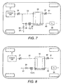
Figure 7 is a schematic diagram of a vehicle with a fuel cell system in which the gas physical quantity detecting device has been employed; -
Figure 8 is a schematic diagram of a vehicle with a fuel cell system in which the gas physical quantity detecting device has been employed; and -
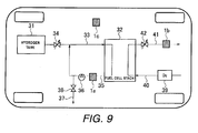
Figure 9 is a schematic diagram of a vehicle with a fuel cell system in which the gas physical quantity detecting device has been employed. - It will be apparent to those skilled in the art from this disclosure that the following descriptions of the embodiments of the present invention are provided for illustration only and not for the purpose of limiting the invention as defined by the appended claims and their equivalents.
- Referring initially to
Figure 1 , a gas physical quantity detecting device is illustrated in accordance with a first embodiment. The constituent features of according to the first embodiment of the present invention will now be explained with reference toFigure 1 . As explained below, in the illustrated embodiment, a physical quantity of a gas can be detected accurately without the occurrence of poor detection results caused by condensed water. The gas physicalquantity detecting device 1 detects a concentration of gas flowing inside agas pipe 2. - The gas physical
quantity detecting device 1 is mounted around anopening 3 in thegas pipe 2 by asensor mounting part 4 of the gas physicalquantity detecting device 1. Thesensor mounting part 4 is a tubular member that is formed around the opening 3 in thegas pipe 2. In this embodiment, an O-ring 5 is arranged between the gas physicalquantity detecting device 1 and thesensor mounting part 4 to provide an airtight seal and prevent gas from leaking between the gas physicalquantity detecting device 1 and thesensor mounting part 4. - The gas physical
quantity detecting device 1 further includes afilter 6 disposed in a bottom portion of thesensor mounting part 4, adetection element chamber 7 defined by an interior of atubular sensor enclosure 8, anelement cover 9 and anelectrical wiring harness 10. Theelement cover 9 is arranged in an upper portion of the inside of thedetection element chamber 7 and contains inside a resistance temperature sensor S. Theelectrical wiring harness 10 receives and transmits a detection signal from the resistance temperature sensor, and supplies electric power to the resistance temperature sensor S. The resistance temperature sensor S detects a concentration of gas that passes from thegas pipe 2 to the resistance temperature sensor S through theopening 3, thefilter 6, and thedetection element chamber 7. The concentration is detected based on a temperature change of the resistance temperature sensor S. Although in this embodiment a resistance temperature sensor is provided inside theelement cover 9 to detect a concentration of the gas, it is also acceptable to change the sensor configuration inside theelement cover 9 so as to detect a temperature, pressure or other physical quantity. In this embodiment, theelement cover 9 is provided with asmall opening 21 for introducing the gas to the resistance temperature sensor S. - The
filter 6 is made by interweaving non-hydrophobic fibers in a non-uniform manner such that thefilter 6 of non-hydrophobic fibers has a three-dimensional form. In other words, thefilter 6 has continuous passageways for gas to pass through thefilter 6 from thegas pipe 2 to thedetection element chamber 7. However, theses continuous passageways of thefilter 6 are non-linear passageways. If the gas of which a physical quantity is being detected contains hydrogen, then it is advantageous for the fiber material to be one of the following stainless steels: SUS316 (a stainless steel 18% Cr, 12% Ni, 2% Mo, 0.08% or less of C added thereto), SUS316L (a stainless steel having 18% Cr, 12% Ni, 2% Mo, 0.03% or less of C added thereto), or SUS304 (a stainless steel containing 18% Cr and 8% Ni). By using one of these fiber materials, thefilter 6 can be prevented from degrading due to exposure to hydrogen and thefilter 6 can be used continuously while exposed to hydrogen without being replaced. - With the gas physical
quantity detecting device 1, as described above, if liquid water is contained in the gas flowing through thegas pipe 2, the liquid water will be blocked by thefilter 6 and prevented from entering into thedetection element chamber 7. As a result, liquid water can be prevented from adhering to theelement cover 9 and causing a poor detection result to occur. Additionally, liquid water is prevented from clogging thefilter 6 and inhibiting the exchange of gas between thegas pipe 2 and thedetection element chamber 7. As a result, the physical quantity of the gas can be detected accurately. - Meanwhile, if water vapor is contained in the gas flowing through the
gas pipe 2, the water vapor will pass through thefilter 6 and enter thedetection element chamber 7. Consequently, there is the possibility that water vapor inside thedetection element chamber 7 will condense and cause condensed water (dew) to exist inside thedetection element chamber 7. However, since thefilter 6 is made by interweaving a non-hydrophobic fiber(s) in a non-uniform manner such that the non-hydrophobic fiber(s) has a three-dimensional form, the surface of thefilter 6 is not a flat plane but, instead, has fine indentations and protrusions. The internal structure of thefilter 6 is such that there are continuous air voids whose sizes change as they interconnect. These air voids form a plurality of paths through which gas can flow. Thus, an air layer occupies a larger portion of the surface of thefilter 6 than in the conventional technology. - In general, the surface tension of water is determined by a contact angle of the water with a surface. In the case of the
filter 6, the non-hydrophobic fiber(s) forms many contact surfaces with water droplets in thefilter 6. In other words, the non-linear passageways of thefilter 6 forms many contact surfaces with water droplets in thefilter 6. When water is spread over a plurality of objects (i.e., fibers), the overall contact angle is calculated as a sum of the individual contact angles weighted based on surface area. Since the contact angle of water with respect to air is 0, the contact angle of water with respect to thefilter 6 that is occupied by an air layer to a large degree is smaller than the contact angle with respect to a conventional filter. Consequently, a liquid film does not form on the surface of the filter due to surface tension and condensed water infiltrates to the interior of thefilter 6 by capillary action. Although a similar effect can be obtained by applying a hydrophilic treatment to the filter, it is necessary to raise the temperature or apply some other process in order to activate the hydrophilic treatment, which causes the cost to increase. - Since the internal structure of the
filter 6 is such that there are continuous air voids whose sizes change as they interconnect, any condensed water that is absorbed into thefilter 6 gathers in places where the surface tension is strong and leaves places that are not filled with liquid water. Additionally, since gas is constantly entering and exiting the upper and lower surfaces of thefilter 6, a situation in which all of the gas paths inside thefilter 6 become clogged does not occur. Even if water condenses inside thedetection element chamber 7, a situation in which gas is blocked to the inside of thedetection element chamber 7 does not occur and a physical quantity of the gas can be detected accurately. - It is advantageous for the sizes of the air voids existing on a surface of the
filter 6 facing toward thedetection element chamber 7 to be smaller than a maximum flame extinguishing diameter (approximately 0.8 mm at atmospheric pressure) of a hydrogen flame at a pressure of a gas flowing inside thegas pipe 2. Thus constructed, even if a spark occurs inside thedetection element chamber 7 while the device is being used in a hydrogen atmosphere, the flame will not spread to thegas pipe 2 side and the flame can be suppressed inside thedetection element chamber 7. - In order that condensed water occurring inside the
detection element chamber 7 will not form a liquid film on aninternal wall surface 8a of thesensor enclosure 8, a hydrophilic treatment is applied to theinternal wall surface 8a or the roughness of theinternal wall surface 8a is made to be larger than the roughness of the surface of theelement cover 9. When such a constituent feature is adopted, even if water condensation occurs inside thedetection element chamber 7, liquid droplets will not adhere to theinternal wall surface 8a. Additionally, since the roughenedinternal wall surface 8a of thedetection element chamber 7 serves as a water condensation kernel, condensed water does not develop on the surface of theelement cover 9. Therefore, poor detection results caused by liquid water adhered to theelement cover 9 can be prevented. A similar technical effect can be obtained by applying a water repellant treatment to theinternal wall surface 8a because doing so will prevent liquid droplets from adhering to theinternal surface 8a. - Variation of the
filter 6 ofFigure 1 will now be explained with reference toFigure 2 to 5 . Since these variations use the same configurations shown inFigure 1 , except for the filter construction, only parts of the gas pipe and the sensor mounting part will be illustrated. The remaining parts of the gas physicalquantity detecting device 1 are the same as inFigure 1 . Also in each of these variations, the filters 6' to 6"" are made of the same material as thefilter 6 of the first embodiment, as discussed above, except that their densities and/or shapes are changed. - In the filter shown in
Figure 2 , the fiber density varies along an axial direction of the filter 6'. More specifically, the filter 6' has afirst filter section 6a with a first fiber density and asecond filter section 6b with a second fiber density that is different than the first fiber density of thefirst filter section 6a. Thesecond filter section 6b is arranged nearer to thedetection element chamber 7 than thefirst filter section 6a, which is arranged nearer to thegas pipe 2. The second fiber density of thesecond filter section 6b is smaller than the first fiber density of thefirst filter section 6a. With this filter configuration, since the second fiber density of thesecond filter section 6b of thedetection element chamber 7 is small, condensed water that develops inside thedetection element chamber 7 can be quickly absorbed into thesecond filter section 6b such that condensed water can be discharged effectively. - In the
filter 6" shown inFigure 3 , the fiber density varies in radial direction of thefilter 6". More specifically, thefilter 6" has thefirst filter section 6a with the first fiber density located in the center with thesecond filter section 6b with the second fiber density surrounding thefirst filter section 6a. The second fiber density of thesecond filter section 6b, which is disposed in a peripheral section, is smaller than the first fiber density of thefirst filter section 6a, which is disposed in a middle section. When gas is exchanged between thegas pipe 2 and thedetection element chamber 7, the flow speed of the gas is zero (0) at the internal wall surface of thesensor mounting part 4. Thus, with this filter configuration, the discharge of water from the peripheralsecond filter section 6b can be promoted because the fiber density of the peripheralsecond filter section 6b is smaller than the fiber density of the middlefirst filter section 6a. - In the
filter 6"' shown inFigure 4 , the surface of thefilter 6"' has a concave shape on the side facing thedetection element chamber 7. With this filter configuration, the surface area of thefilter 6"' on the side facing thedetection element chamber 7 is larger than if the surface was planar. Consequently, condensed water produced inside thedetection element chamber 7 can be discharged even more effectively. - In the
filter 6"" shown inFigure 5 , thefilter 6"" has a multiple layered structure having gaps in-between layers (the example shown inFigure 5 has a three layered structure comprising three filters L1, L2 and L3). With this filter configuration, the volume of the air voids in thefilter 6"" can be increased. As a result, even if a large amount of condensed water develops or a large amount of liquid water flows in from thegas pipe 2, the penetration of liquid water into thedetection element chamber 7 can be prevented in an effective manner. - Referring now to
Figure 6 , a gas physical quantity detecting device 1' in accordance with a second embodiment will now be explained. In view of the similarity between the first and second embodiments, the parts of the second embodiment that are identical to the parts of the first embodiment will be given the same reference numerals as the parts of the first embodiment. Moreover, the descriptions of the parts of the second embodiment that are identical to the parts of the first embodiment may be omitted for the sake of brevity. - As shown in
Figure 6 , there are mainly three basic differences between the first and second embodiments. First, in the second embodiment, a two part filter of the gas physical quantity detecting device 1' includes afirst filter section 6a with the first fiber density located in the center with asecond filter section 6b with a second fiber density surrounding thefirst filter section 6a. Second, in the second embodiment, thesensor enclosure 8 of the gas physical quantity detecting device 1' further includes an innertubular member 8b. Third, in the second embodiment, the element cover of the gas physical quantity detecting device 1' has adetection element cover 9a and areference element cover 9b. The parts that are different will now be explained. - In this second embodiment, the inner
tubular member 8b is provided inside on the internal wall of thesensor enclosure 8. The innertubular member 8b extends to a bottom portion of thesensor mounting part 4. Thus, the innertubular member 8b forms thedetection element chamber 7. Thefirst filter section 6a is arranged in a bottom portion of the innertubular member 8b. Thesecond filter section 6b is arranged on an internal wall surface of the innertubular member 8b and extends along the entire area of the internal wall surface of the innertubular member 8b. Although in this embodiment thefirst filter section 6a is arranged at least partially inside thedetection element chamber 7, it is acceptable for the filter to be arranged outside the detection element chamber 7 (as shown inFigure 1 ) so long as the filter is between thegas pipe 2 and thedetection element chamber 7. - The
first filter section 6a is made of the same material as thefilter 6 of the first embodiment as discussed above. Thefirst filter section 6a is configured and arranged such that a surface thereof that is nearer to thegas pipe 2 protrudes into thegas pipe 2 through theopening 3. By configuring thefirst filter section 6a such that the surface thereof facing thegas pipe 2 protrudes into thegas pipe 2, moisture absorbed by thefirst filter section 6a can be carried away by gas flowing through thegas pipe 2. As a result, liquid water inside thedetection element chamber 7 can be discharged in an effective manner. - The
second filter section 6b is made of the same material as thefilter 6 of the first embodiment as discussed above, and is provided on the internal wall surface of the innertubular member 8b. Providing thesecond filter section 6b enables condensed water inside thedetection element chamber 7 to be absorbed at the side wall portions in addition to the bottom portion of thedetection element chamber 7. As a result, liquid water can be prevented from adhering to adetection element cover 9a and areference element cover 9b, which are described later. Since thefirst filter section 6a serves as a kernel for water condensation, condensation of water on the surfaces of theelement cover 9a and thereference element cover 9b can be prevented. The second fiber density of thesecond filter section 6b, which is disposed in a peripheral section, is smaller than the first fiber density of thefirst filter section 6a, which is disposed in a middle section, similar toFigure 3 . - The
detection element cover 9a and thereference element cover 9b are arranged inside thedetection element chamber 7. Thedetection element cover 9a contains a resistance temperature sensor S1 for gas detection inside. Thedetection element cover 9a has anarrow hole 21. Thereference element cover 9b contains a reference resistance temperature sensor S2 and a reference (comparative) gas. Thereference element cover 9b is sealed. Together, the sensors S1 and S2 form a thermal conductivity hydrogen sensor that detects a hydrogen concentration based on a temperature change of the gas detection resistance temperature sensor S1 (which changes in accordance with the hydrogen concentration of the gas) while compensating based on a temperature change of the reference resistance temperature sensor S2. With this configuration, the hydrogen concentration can be detected accurately even if the hydrogen concentration is high, there is no oxygen present, and water vapor exists. - When the thermal conductivity hydrogen sensor (S1 and S2) is used, if there is a flow of gas inside the
detection element cover 9a, then the detection value will be affected because the temperature of the gas detection resistance temperature sensor S1 will change due to the heat transfer coefficient in addition to the thermal conductivity. Therefore, it is advantageous to take such measures as making the thickness of thefirst filter section 6a ten (10) mm or larger and making the diameter of thegas pipe 2 larger at the position where the gas physical quantity detecting device 1' is mounted than at other positions in order to suppress the occurrence of gas flow inside thedetection element cover 9a. - When the
first filter section 6a has absorbed liquid water, there is the possibility that liquid water will be splashed from thefirst filter section 6a toward thedetection element chamber 7 if the flow rate of gas inside thegas pipe 2 increases abruptly. Therefore, it is beneficial for a gap of several millimeters to be provided between thefirst filter section 6a and thedetection element cover 9a. By providing such a gap, splashed water can be prevented from adhering to the surface of thedetection element cover 9a. - It is advantageous to apply a water repellent treatment to the surfaces of both the
detection element cover 9a and thereference element cover 9b. By applying a water repellent treatment to both surfaces, liquid droplets can be prevented from adhering to the surfaces of thedetection element cover 9a and thereference element cover 9b even when liquid water absorbed by thefirst filter section 6a is splashed onto the surfaces of thedetection element cover 9a and thereference element cover 9b or when water condenses on the surfaces of thedetection element cover 9a and thereference element cover 9b. As a result, poor detection results can be prevented. - It is beneficial for a gap to be provided between the
detection element cover 9a and thereference element cover 9b. By providing a gap, even if liquid droplets adhere to the surface of either thedetection element cover 9a or thereference element cover 9b, a situation in which poor detection results occur due to the formation of a liquid film spanning between thedetection element cover 9a and thereference element cover 9b can be prevented. - It is beneficial to provide a gap between the internal wall of the
detection element chamber 7 and both thedetection element cover 9a and thereference element cover 9b. By providing such a gap, even if liquid droplets adhere to the internal wall of thedetection element chamber 7 and to the surface of either thedetection element cover 9a or thereference element cover 9b, a situation in which poor detection results occur due to the formation of a liquid film spanning between the internal wall of thedetection element chamber 7, thedetection element cover 9a, and thereference element cover 9b can be prevented. - The gas physical
quantity detecting devices 1 and 1' (including the filter variations ofFigures 2 to 5 ) can be employed in a fuel cell system of a vehicle like those shown inFigures 7 to 9 to generate electric power for driving a vehicle. Thus, the fuel cell system ofFigures 7 to 9 function a drive source for the vehicle. - Three examples 1 to 3 in which one of the gas physical
quantity detecting devices 1 and 1' (including the filter variations ofFigures 2 to 5 ) is employed in a fuel cell system will now be explained with reference toFigures 7 to 9 . When one of these fuel cell systems is installed in a vehicle, it is advantageous for the gas physicalquantity detecting devices 1 and 1' (including the filter variations ofFigures 2 to 5 ) to extend in a generally vertically upward direction form thegas pipe 2. It is not necessary, however, for thegas pipe 2 to be arranged horizontally. It is acceptable for thegas pipe 2 to be slanted. It is also advantageous for the gas physicalquantity detecting devices 1 and 1' (including the filter variations ofFigures 2 to 5 ) to be arranged such that its tilt angle stays within ± 40° when the vehicle tilts. - Referring now to
Figure 7 , the fuel cell system basically includes ahydrogen tank 31, afuel cell stack 32, ahydrogen supply pipe 33, and a hydrogenpressure reducing valve 34. Thefuel cell stack 32 includes a plurality of stacked fuel cells with each stacked fuel cell having a fuel electrode and an oxidant electrode to generate electricity using hydrogen supplied to the fuel electrode and air supplied to the oxidant electrode. Each of the fuel cells is a solid polymer fuel cell comprising a membrane-electrode composite body and separators. The membrane-electrode composite body includes catalyst layers of the fuel electrode and the oxidant electrode and a solid electrolyte membrane pinched between gas dispersion electrodes. The separators have gas flow passages for supplying hydrogen to the fuel electrode and air to the oxidant electrode. The separators are arranged to sandwich the membrane-electrode composite body. The electrochemical reactions that take place at the fuel electrode and the oxidant electrode and the electrochemical reaction of the fuel cell as a whole are shown below in the chemical equations (1) to (3).
Fuel electrode: H2 → 2H+ + 2e- (1)
Oxidant electrode: ½O2 + 2H+ + 2e- → H2O (2)
Overall: H2 +½O2 → H2O (3)
- The hydrogen
pressure reducing valve 34 serves to reduce the pressure of the high pressure hydrogen inside thehydrogen tank 31 to a pressure that is well suited to the operating conditions of thefuel cell tank 32. Thehydrogen supply pipe 33 serves to deliver the hydrogen to the fuel electrode of thefuel cell stack 32. - A
hydrogen circulation pipe 35 and acirculation pump 36 are provided on an outlet side of the fuel electrode and serve to circulate gas discharged from the fuel electrode to thehydrogen supply pipe 33. Ahydrogen discharge pipe 37 extends from thehydrogen circulation pipe 35 to discharge gas from the fuel electrode to the outside. A hydrogen discharge on-offvalve 38 opens and closes thehydrogen discharge pipe 37. - The fuel cell system also has a
compressor 39 and anair supply pipe 40. Thecompressor 39 serves to supply compressed air to the oxidant electrode of thefuel cell stack 32 through theair supply pipe 40. Anair discharge pipe 41 extends from theair discharge pipe 41 to discharge air from the oxidant electrode to the outside. An air discharge on-offvalve 42 opens and closes theair discharge pipe 41. - In this fuel cell system, one of the gas physical
quantity detecting devices 1 and 1' (including the filter variations ofFigures 2 to 5 ) is provided on thehydrogen discharge pipe 35 for detecting a concentration of hydrogen contained in a gas discharged from the fuel electrode. The fuel cell system is configured to control the opening degrees of the hydrogenpressure regulating valve 34 and the hydrogen discharge on-offvalve 38 based on the hydrogen concentration detected by the gas physicalquantity detecting device 1 or 1'. - Although one of the gas physical
quantity detecting devices 1 and 1' (including the filter variations ofFigures 2 to 5 ) is provided upstream of thecirculation pump 36 in the first example, it is acceptable for one of the gas physicalquantity detecting devices 1 and 1' (including the filter variations ofFigures 2 to 5 ) to be provided downstream of thecirculation pump 36 or downstream of the hydrogenpressure regulating valve 34. However, if one of the detecting devices is provided on the downstream side of thecirculation pump 36, then the detection error will be larger than when the detection device is provided on the upstream side of thecirculation pump 36 because the gas flow speed is higher on the downstream side. - Meanwhile, if the detection device is provided in the
hydrogen supply pipe 33, then the detection error will be larger than when thedetection device 1 is provided on the upstream side of thecirculation pump 36 because a high hydrogen concentration will be detected at all times and the gas flow rate is higher in thehydrogen supply pipe 33. As a result, it is beneficial for the gas physicalquantity detecting devices 1 and 1' (including the filter variations ofFigures 2 to 5 ) to be provided on the upstream side of thecirculation pump 36. - Referring now to
Figure 8 , the fuel cell system does not have thehydrogen circulation pipe 35 or thecirculation pump 36 of the first example. The hydrogen discharged from the fuel electrode is discharged directly to the outside of the system through thehydrogen discharge pipe 37 and the hydrogen discharge on-offvalve 38. In this fuel cell system, similarly to first example, one of the gas physicalquantity detecting devices 1 and 1' (including the filter variations ofFigures 2 to 5 ) is provided on thehydrogen discharge pipe 35 for detecting a concentration of hydrogen contained in a gas discharged from the fuel electrode. The fuel cell system is configured to control the opening degrees of the hydrogenpressure regulating valve 34 and the hydrogen discharge on-offvalve 38 based on the hydrogen concentration detected by the gas physical quantity detecting device. - Referring now to
Figure 9 , the fuel cell system has generally the same constituent features as the fuel cell system shown inFigure 7 . However, in this fuel cell system, three gas physicalquantity detecting devices quantity detecting devices quantity detecting devices 1 and 1' (including the filter variations ofFigures 2 to 5 ) as discussed above. The gas physicalquantity detecting device 1a is provided in thehydrogen discharge pipe 35. The gas physicalquantity detecting device 1b is provided in theair discharge pipe 41. The gas physicalquantity detecting device 1c is provided in a position outside of the fuel cell system. Thus, a concentration of hydrogen contained in gas discharged from the fuel electrode, a concentration of hydrogen contained in gas discharged from the oxidant electrode, and a concentration of hydrogen contained in gas discharged from the fuel cell system are detected. The position outside of the fuel cell system can be, for example, near thefuel cell stack 32 or inside a vehicle cabin if the fuel cell system is installed in a vehicle. With this configuration, a leakage of hydrogen into the air discharge pipe 41 (through which high-humidity gas flows) or a leakage of hydrogen from the fuel cell system can be detected. - While only selected embodiments have been chosen to illustrate the present invention, it will be apparent to those skilled in the art from this disclosure that various changes and modifications can be made herein without departing from the scope of the invention as defined in the appended claims. For example, the size, shape, location or orientation of the various components can be changed as needed and/or desired. Components that are shown directly connected or contacting each other can have intermediate structures disposed between them. The functions of one element can be performed by two, and vice versa. The structures and functions of one embodiment can be adopted in another embodiment. It is not necessary for all advantages to be present in a particular embodiment at the same time. Every feature which is unique from the prior art, alone or in combination with other features, also should be considered a separate description of further inventions by the applicant, including the structural and/or functional concepts embodied by such feature(s). Thus, the foregoing descriptions of the embodiments according to the present invention are provided for illustration only, and not for the purpose of limiting the invention as defined by the appended claims and their equivalents.
- This application claims priority from Japanese Patent Application No.
2007-230161, filed 5th September 2007
Claims (15)
- An apparatus, comprising:detection means for detecting a physical quantity of a gas flowing through a gas flow passage;chamber means for containing the detection means and arranged to supply gas from inside the gas flow passage to the detection means; andfilter means arranged between the gas flow passage and the chamber means, the filter means having a predetermined thickness and being made of a non-hydrophobic material.
- An apparatus as claimed in claim 1, wherein the non-hydrophobic material has fibers interwoven in a non-uniform manner such that the filter means has a three-dimensional form.
- An apparatus as claimed in claim 2, wherein the fibers of the filter means comprise a stainless steel having a composition of one of SUS316 and SUS304.
- An apparatus as claimed in claim 2 or claim 3, wherein the fibers are arranged to form gaps between the fibers on a surface of the filter means that faces the chamber means in which the gaps are smaller than a maximum flame extinguishing diameter of a hydrogen flame.
- An apparatus as claimed in any preceding claim, wherein the filter means has a multiple layered structure with a space provided between adjacent layers.
- An apparatus as claimed in claim 2 or any claim dependent on claim 2, wherein the filter means:has a fiber density at a peripheral portion of the filter means that is lower than a fiber density at a middle portion of the filter means; and/orhas a fiber density on a side of the filter means nearer to the chamber means that is lower than a fiber density on a side of the filter means nearer to the gas passage.
- An apparatus as claimed in any preceding claim, wherein the filter means:has a recessed shaped surface that faces the chamber means; and/orat least partially extends along an internal side wall surface of the chamber means.
- An apparatus as claimed in any preceding claim, wherein the chamber means has an internal wall surface with a water repellent treatment and/or a hydrophilic treatment.
- An apparatus as claimed in any preceding claim, wherein the detection means comprises a cover member, and wherein the chamber means has an internal wall surface with a surface roughness that is larger than a surface roughness of a surface of the cover member that faces the chamber means.
- An apparatus as claimed in any preceding claim, wherein the detection means comprises a cover member with a surface of the cover member facing the chamber means having a water repellent treatment.
- An apparatus as claimed in any preceding claim, wherein the detection means comprises a first sensor in a first cover and a second sensor in a second cover, with the first cover having a gas introducing hole and the second sensor being a reference sensor with the second cover containing a reference gas.
- An apparatus as claimed in claim 11, wherein the first and second cover members:are spaced apart with a gap therebetween; and/orare spaced inwardly from an internal side wall of the chamber means.
- A fuel cell system comprising:a fuel cell with a fuel electrode;a pipe arranged to supply a gas to the fuel electrode of the fuel cell;a pipe arranged to discharge the gas from the fuel electrode; andan apparatus as claimed in any preceding claim connected to at least one of the pipes.
- A fuel cell system comprising a fuel cell that receives hydrogen and an apparatus as claimed in any of claims 1 to 12 arranged in an area to detect leakage of hydrogen from the fuel cell system.
- A vehicle, comprising:a vehicle body supporting a fuel cell system as claimed in claim 13 or claim 14; andat least one drive wheel arranged to use electric power generated by the fuel cell system as a drive source.
Applications Claiming Priority (1)
| Application Number | Priority Date | Filing Date | Title |
|---|---|---|---|
| JP2007230161A JP2009063352A (en) | 2007-09-05 | 2007-09-05 | Gas physical quantity detection device, fuel cell system, vehicle |
Publications (1)
| Publication Number | Publication Date |
|---|---|
| EP2034307A1 true EP2034307A1 (en) | 2009-03-11 |
Family
ID=40020774
Family Applications (1)
| Application Number | Title | Priority Date | Filing Date |
|---|---|---|---|
| EP08163633A Withdrawn EP2034307A1 (en) | 2007-09-05 | 2008-09-03 | Gas physical quantity detecting device, fuel cell system and vehicle |
Country Status (4)
| Country | Link |
|---|---|
| US (1) | US20090061261A1 (en) |
| EP (1) | EP2034307A1 (en) |
| JP (1) | JP2009063352A (en) |
| CA (1) | CA2639338A1 (en) |
Cited By (1)
| Publication number | Priority date | Publication date | Assignee | Title |
|---|---|---|---|---|
| EP2722660A3 (en) * | 2012-10-22 | 2014-04-30 | Freescale Semiconductor, Inc. | Packaging for semiconductor sensor devices and methods |
Families Citing this family (11)
| Publication number | Priority date | Publication date | Assignee | Title |
|---|---|---|---|---|
| FR2950740A1 (en) | 2009-09-25 | 2011-04-01 | Michelin Soc Tech | ELECTROCHEMICAL REACTOR, SUCH AS A FUEL CELL OR ELECTROLYSER, EQUIPPED WITH A DEVICE FOR MEASURING THE CONCENTRATION IN A GAS OF ONE OF THE SPECIFIC GASES OF THE OPERATION OF SAID REACTOR |
| US8196448B2 (en) * | 2010-01-20 | 2012-06-12 | GM Global Technology Operations LLC | Hydrogen sensor assembly |
| JP6369217B2 (en) * | 2014-08-20 | 2018-08-08 | スズキ株式会社 | Fuel cell motorcycle |
| JP6265166B2 (en) * | 2015-03-31 | 2018-01-24 | 富永 淳 | Monitoring system for hydrogen leakage from conduit |
| JP6388857B2 (en) * | 2015-09-07 | 2018-09-12 | 株式会社豊田自動織機 | Fuel cell system |
| JP6610198B2 (en) * | 2015-11-24 | 2019-11-27 | スズキ株式会社 | Hydrogen detector for fuel cell vehicle |
| CN105527414B (en) * | 2015-12-31 | 2018-10-30 | 无锡市尚沃医疗电子股份有限公司 | The method and apparatus for measuring a variety of exhaled gas concentration using a gas sensor |
| CN113490836B (en) * | 2019-03-04 | 2024-12-17 | 日立安斯泰莫株式会社 | Physical quantity detecting device |
| JP7334672B2 (en) * | 2020-05-01 | 2023-08-29 | トヨタ自動車株式会社 | Hydrogen leak detection mechanism |
| DE102022131802A1 (en) * | 2022-11-30 | 2024-06-06 | Knorr-Bremse Systeme für Nutzfahrzeuge GmbH | Pressure sensor element |
| DE102022214190A1 (en) | 2022-12-21 | 2024-06-27 | Vitesco Technologies GmbH | Method for diagnosing a gas concentration sensor, gas concentration sensor, computer program and computer-readable medium |
Citations (7)
| Publication number | Priority date | Publication date | Assignee | Title |
|---|---|---|---|---|
| JPH1130535A (en) | 1997-07-11 | 1999-02-02 | Mitsubishi Electric Corp | Pressure sensor device |
| US20040052683A1 (en) * | 2002-06-05 | 2004-03-18 | Snap-On Technologies, Inc. | Portable vehicle exhaust analyzer module |
| EP1452853A1 (en) * | 2001-11-15 | 2004-09-01 | Riken Keiki Co., Ltd. | Gas sensor |
| EP1469545A2 (en) * | 2003-04-10 | 2004-10-20 | Hewlett-Packard Development Company, L.P. | Regulated hydrogen production system |
| US20060048562A1 (en) * | 2004-09-03 | 2006-03-09 | Hidetoshi Oishi | Gas sensor and control method therefor |
| US20060118416A1 (en) * | 2004-12-08 | 2006-06-08 | Honeywell International, Inc. | Electrochemical sensor system |
| JP2007230161A (en) | 2006-03-03 | 2007-09-13 | Nippon Zeon Co Ltd | Manufacturing method of injection molded body |
-
2007
- 2007-09-05 JP JP2007230161A patent/JP2009063352A/en active Pending
-
2008
- 2008-06-26 US US12/146,817 patent/US20090061261A1/en not_active Abandoned
- 2008-09-03 EP EP08163633A patent/EP2034307A1/en not_active Withdrawn
- 2008-09-05 CA CA002639338A patent/CA2639338A1/en not_active Abandoned
Patent Citations (8)
| Publication number | Priority date | Publication date | Assignee | Title |
|---|---|---|---|---|
| JPH1130535A (en) | 1997-07-11 | 1999-02-02 | Mitsubishi Electric Corp | Pressure sensor device |
| US6003379A (en) * | 1997-07-11 | 1999-12-21 | Mitsubishi Denki Kabushiki Kaisha | Pressure sensor device |
| EP1452853A1 (en) * | 2001-11-15 | 2004-09-01 | Riken Keiki Co., Ltd. | Gas sensor |
| US20040052683A1 (en) * | 2002-06-05 | 2004-03-18 | Snap-On Technologies, Inc. | Portable vehicle exhaust analyzer module |
| EP1469545A2 (en) * | 2003-04-10 | 2004-10-20 | Hewlett-Packard Development Company, L.P. | Regulated hydrogen production system |
| US20060048562A1 (en) * | 2004-09-03 | 2006-03-09 | Hidetoshi Oishi | Gas sensor and control method therefor |
| US20060118416A1 (en) * | 2004-12-08 | 2006-06-08 | Honeywell International, Inc. | Electrochemical sensor system |
| JP2007230161A (en) | 2006-03-03 | 2007-09-13 | Nippon Zeon Co Ltd | Manufacturing method of injection molded body |
Cited By (2)
| Publication number | Priority date | Publication date | Assignee | Title |
|---|---|---|---|---|
| EP2722660A3 (en) * | 2012-10-22 | 2014-04-30 | Freescale Semiconductor, Inc. | Packaging for semiconductor sensor devices and methods |
| US8946833B2 (en) | 2012-10-22 | 2015-02-03 | Freescale Semiconductor, Inc. | Packaging for semiconductor sensor devices and methods |
Also Published As
| Publication number | Publication date |
|---|---|
| CA2639338A1 (en) | 2009-03-05 |
| JP2009063352A (en) | 2009-03-26 |
| US20090061261A1 (en) | 2009-03-05 |
Similar Documents
| Publication | Publication Date | Title |
|---|---|---|
| EP2034307A1 (en) | Gas physical quantity detecting device, fuel cell system and vehicle | |
| TWI382578B (en) | Multi-layer fuel cell diffuser | |
| CN109565097A (en) | Defogging system for electrochemical cell | |
| US8227133B2 (en) | Fuel cell system | |
| JP2019128182A (en) | Gas characteristic detection device, and fuel cell system | |
| CN106605327B (en) | Fuel Cells and Motor Vehicles | |
| US7972745B2 (en) | PEM fuel cell system with a porous hydrophobloc plug for maintaining system back pressure and methods for designing the plug and for designing systems for using the plug | |
| JP5192919B2 (en) | Gas sensor | |
| US20140077402A1 (en) | Humidification cell | |
| JP2007311066A (en) | Fuel cell and manufacturing method thereof | |
| JP5144383B2 (en) | Gas sensor | |
| JP2013196905A (en) | Fuel cell system | |
| US8916313B2 (en) | Fuel cell | |
| JP4630133B2 (en) | Gas sensor | |
| JP5291379B2 (en) | Fuel cell vehicle | |
| JP6420801B2 (en) | Fuel cell stack | |
| JP4321264B2 (en) | Fuel cell and fuel cell separator | |
| JP2005302709A5 (en) | ||
| JP5065601B2 (en) | Fuel cell stack | |
| JP4695441B2 (en) | Gas sensor | |
| JP4415678B2 (en) | Fuel cell | |
| JP4575846B2 (en) | Gas sensor | |
| JP2007294340A (en) | Fuel cell | |
| JP2006252923A (en) | Fuel cell | |
| JP2005183066A (en) | Fuel cell and gas separator for fuel cell |
Legal Events
| Date | Code | Title | Description |
|---|---|---|---|
| PUAI | Public reference made under article 153(3) epc to a published international application that has entered the european phase |
Free format text: ORIGINAL CODE: 0009012 |
|
| AK | Designated contracting states |
Kind code of ref document: A1 Designated state(s): AT BE BG CH CY CZ DE DK EE ES FI FR GB GR HR HU IE IS IT LI LT LU LV MC MT NL NO PL PT RO SE SI SK TR |
|
| AX | Request for extension of the european patent |
Extension state: AL BA MK RS |
|
| 17Q | First examination report despatched |
Effective date: 20090925 |
|
| 17P | Request for examination filed |
Effective date: 20090827 |
|
| AKX | Designation fees paid |
Designated state(s): DE FR GB |
|
| STAA | Information on the status of an ep patent application or granted ep patent |
Free format text: STATUS: THE APPLICATION IS DEEMED TO BE WITHDRAWN |
|
| 18D | Application deemed to be withdrawn |
Effective date: 20100206 |