EP2034183A2 - Suction structure in piston type compressor - Google Patents
Suction structure in piston type compressor Download PDFInfo
- Publication number
- EP2034183A2 EP2034183A2 EP08163561A EP08163561A EP2034183A2 EP 2034183 A2 EP2034183 A2 EP 2034183A2 EP 08163561 A EP08163561 A EP 08163561A EP 08163561 A EP08163561 A EP 08163561A EP 2034183 A2 EP2034183 A2 EP 2034183A2
- Authority
- EP
- European Patent Office
- Prior art keywords
- passage
- chamber
- valve body
- valve
- suction
- Prior art date
- Legal status (The legal status is an assumption and is not a legal conclusion. Google has not performed a legal analysis and makes no representation as to the accuracy of the status listed.)
- Withdrawn
Links
Images




Classifications
-
- F—MECHANICAL ENGINEERING; LIGHTING; HEATING; WEAPONS; BLASTING
- F04—POSITIVE - DISPLACEMENT MACHINES FOR LIQUIDS; PUMPS FOR LIQUIDS OR ELASTIC FLUIDS
- F04B—POSITIVE-DISPLACEMENT MACHINES FOR LIQUIDS; PUMPS
- F04B27/00—Multi-cylinder pumps specially adapted for elastic fluids and characterised by number or arrangement of cylinders
- F04B27/08—Multi-cylinder pumps specially adapted for elastic fluids and characterised by number or arrangement of cylinders having cylinders coaxial with, or parallel or inclined to, main shaft axis
- F04B27/14—Control
- F04B27/16—Control of pumps with stationary cylinders
- F04B27/18—Control of pumps with stationary cylinders by varying the relative positions of a swash plate and a cylinder block
- F04B27/1804—Controlled by crankcase pressure
-
- F—MECHANICAL ENGINEERING; LIGHTING; HEATING; WEAPONS; BLASTING
- F04—POSITIVE - DISPLACEMENT MACHINES FOR LIQUIDS; PUMPS FOR LIQUIDS OR ELASTIC FLUIDS
- F04B—POSITIVE-DISPLACEMENT MACHINES FOR LIQUIDS; PUMPS
- F04B27/00—Multi-cylinder pumps specially adapted for elastic fluids and characterised by number or arrangement of cylinders
- F04B27/08—Multi-cylinder pumps specially adapted for elastic fluids and characterised by number or arrangement of cylinders having cylinders coaxial with, or parallel or inclined to, main shaft axis
- F04B27/14—Control
- F04B27/16—Control of pumps with stationary cylinders
- F04B27/18—Control of pumps with stationary cylinders by varying the relative positions of a swash plate and a cylinder block
- F04B27/1804—Controlled by crankcase pressure
- F04B2027/184—Valve controlling parameter
- F04B2027/1859—Suction pressure
Definitions
- the present invention relates to a suction structure for allowing refrigerant from a suction pressure region in a piston type compressor. More specifically, the compressor has a rotary valve integrally rotated with a rotary shaft and having a supply passage for introducing refrigerant from the suction pressure region into a compression chamber defined in a cylinder bore by a piston.
- piston type compressors there are two types of suction valves.
- One is a rotary valve as disclosed in Unexamined Japanese Patent Publications No. 7-119631 and No. 2006-083835 .
- the other is a reed valve as disclosed in Unexamined Japanese Patent Publications No. 64-088064 and No. 2000-145629 .
- the piston type compressor with the rotary valve has lower suction resistance in introducing refrigerant into cylinder bores, and has superior energy efficiency, compared to the piston type compressor with the reed valve.
- the rotary valve rotating with a rotary shaft is provided so as to be movable in axial direction of the rotary shaft.
- the rotary valve is moved in the axial direction of the rotary shaft depending on the pressure applied to a control pressure chamber.
- the rotary valve is formed with a bypass groove that allows almost all cylinder bores to communicate with a suction port provided in the center of a cylinder block.
- the rotary valve is placed in the axial direction of the rotary shaft so that almost all the cylinder bores communicate with the suction port through the bypass groove when the compressor is started and stopped. Therefore, even when a piston is moved to compress refrigerant in the cylinder bore at the start of the compressor, the refrigerant in the cylinder bore is returned to the suction port through the bypass groove. The shock at the start of the compressor does not occur, accordingly.
- the rotary valve In order to prevent leakage of refrigerant along the periphery of the rotary valve, and also to allow the rotation of the rotary valve, the rotary valve requires minimum clearance around the periphery thereof. Additionally, the rotary valve movable in the axial direction of the rotary shaft requires the clearance that also allows the movement of the rotary valve in the axial direction of the rotary shaft. Such clearance is difficult to set appropriately.
- a compressor disclosed in Unexamined Japanese Patent Publication No. 2000-145629 includes a pressure-differential detecting valve.
- the valve is opened and closed depending on the pressure differential between discharge pressure and suction pressure.
- the valve is located between a suction chamber in the compressor and a low-pressure refrigerant passage that introduces refrigerant from the outside of the compressor.
- the pressure-differential detecting valve is closed, so that no refrigerant flows into the suction chamber from the outside of the compressor. As a result, the shock at the start of the compressor is suppressed.
- a compressor disclosed in Unexamined Japanese Patent Publication No. 7-139474 includes a starting-load reducing device.
- the device is located in a suction passage connected to a suction chamber.
- the device includes a spool valve that constitutes an oil damper. Clearance is provided between a damper portion of the spool valve and a housing.
- refrigerant remains in the suction chamber even when the suction passage is closed by the spool valve.
- the residual refrigerant is introduced into cylinder bores and compressed therein.
- refrigerant remains in the suction chamber even when the pressure-differential detecting valve is closed.
- the residual refrigerant is introduced into cylinder bores and compressed therein. Since the suction chamber generally has large volume to suppress the suction pulsation, large amount of refrigerant is introduced into the cylinder bores even when the pressure-differential detecting valve or the suction passage is closed. Therefore, the shock at the start of the compressor is not sufficiently suppressed.
- the present invention is directed to further suppression of the shock at the start of the compressor.
- a suction structure allows refrigerant from a suction pressure region in a piston type compressor.
- Cylinder bores for accommodating a respective piston are arranged around a rotary shaft.
- the piston is coupled to the rotary shaft through a cam body so that the rotation of the rotary shaft is transmitted to the piston.
- a compression chamber is defined by the piston in the respective cylinder bore.
- a rotary valve has a supply passage for introducing the refrigerant from the suction pressure region to the compression chamber.
- the rotary valve is rotated integrally with the rotary shaft.
- the supply passage has an outlet and an inlet.
- the suction structure includes a shifting device for shifting between a connecting state and a disconnecting state.
- the shifting device includes a valve body, a return spring, a backpressure chamber, and a backpressure passage.
- the valve body is movable between a connecting position and a disconnecting position.
- the connecting position corresponds to the connecting state and the disconnecting position corresponds to the disconnecting state.
- the return spring urges the valve body from the connecting position toward the disconnecting position.
- the backcpressure chamber is defined by the valve body.
- the backpressure passage communicates with the suction pressure region and the backpressure chamber.
- the suction structure further includes a bleed passage and a check valve.
- the bleed passage communicates with the suction pressure region and the backpressure chamber.
- the check valve allows a fluid to flow from the backpressure chamber into the bleed passage.
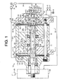
- Fig. 1 shows a piston type compressor 10 according to the first embodiment.
- the compressor 10 is of a fixed displacement type. It is noted that the left side and right side of the compressor 10 as viewed in Fig. 1 are the front and rear sides thereof, respectively.
- the compressor 10 has a pair of cylinder blocks 11, 12.
- a front housing 13 is connected to the cylinder block 11.
- a rear housing 14 is connected to the cylinder block 12.
- the cylinder blocks 11, 12, the front housing 13, and the rear housing 14 constitute a housing assembly of the compressor 10.
- a discharge chamber 131 as a discharge pressure region in the compressor 10 is defined in the front housing 13.
- a discharge chamber 141 as the discharge pressure region in the compressor 10 is defined in the rear housing 14.
- a suction chamber 142 as a suction pressure region in the compressor 10 is defined in the rear housing 14. It is noted that “in the compressor” used hereinafter is the inside of the housing assembly, and that “out of the compressor” is the outside of the housing assembly.
- a valve port plate 15, a valve plate 16, and a retainer plate 17 are interposed between the cylinder block 11 and the front housing 13.
- a valve port plate 18, a valve plate 19, and a retainer plate 20 are Interposed between the cylinder block 12 and the rear housing 14.
- the valve port plates 15, 18 are formed with discharge ports 151, 181, respectively.
- the valve plates 16, 19 are formed with discharge valves 161, 191 opening and closing the discharge ports 151,181, respectively.
- the retainer plates 17, 20 are formed with retainers 171, 201 regulating the opening degrees of the discharge valves 161, 191, respectively.
- the cylinder blocks 11, 12 rotatably support a rotary shaft 21.
- the cylinder blocks 11, 12 are formed with shaft holes 111, 121 extending therethrough, respectively.
- the rotary shaft 21 is inserted into the shaft holes 111, 121.
- the outer peripheral surface of the rotary shaft 21 is in contact with the inner peripheral surfaces of the shaft holes 111, 121.
- the cylinder blocks 11, 12 support directly the rotary shaft 21 through the inner peripheral surfaces of the shaft holes 111, 121, respectively.
- the outer peripheral surface of the rotary shaft 21 has a sealing surface 211 in contact with the shaft hole 111 and has a sealing surface 212 in contact with the shaft hole 121.
- the compressor 10 has a swash plate 23 serving as a cam body and fixed to the rotary shaft 21.
- the swash plate 23 is accommodated in a crank chamber 24 defined between the cylinder blocks 11, 12.
- a lip-type seal member 22 is interposed between the front housing 13 and the rotary shaft 21.
- the seal member 22 prevents leakage of refrigerant between the front housing 13 and the rotary shaft 21.
- the front end of the rotary shaft 21 protruding out of the front housing 13 is connected to a vehicle engine 26 as an external drive source through an electromagnetic clutch 25.
- the rotary shaft 21 receives driving force from the vehicle engine 26 through the electromagnetic clutch 25.
- the cylinder block 11 is formed with a plurality of cylinder bores 27 arranged around the rotary shaft 21.
- the cylinder block 12 is formed with a plurality of cylinder bores 28 arranged around the rotary shaft 21.
- Each cylinder bore 28 of the cylinder block 12 is paired with the opposite cylinder bore 27 of the cylinder block 11.
- Each pair of cylinder bores 27,28 accommodates therein a double-headed piston 29.
- the double-headed piston 29 is coupled to the swash plate 23 through a pair of shoes 30.
- the swash plate 23 rotates integrally with the rotary shaft 21.
- the rotary motion of the swash plate 23 is transmitted to the double-headed piston 29 through the shoes 30, so that the double-headed piston 29 reciprocates in the pair of cylinder bores 27, 28.
- the double-headed piston 29 defines compression chambers 271, 281 in the respective cylinder bores 27, 28.
- the rotary shaft 21 is formed therein with an in-shaft passage 31.
- the in-shaft passage 31 extends along a rotational axis 210 of the rotary shaft 21.
- the in-shaft passage 31 has an inlet 311 and outlets 312, 313.
- the inlet 311 is formed at an end surface 213 of the rotary shaft 21 in the cylinder block 12.
- the inlet 311 is open to the suction chamber 142 in the rear housing 14.
- the outlet 312 is open at the sealing surface 211 of the rotary shaft 21 in the shaft hole 111.
- the outlet 313 is open at the sealing surface 212 of the rotary shaft 21 in the shaft hole 121.
- the cylinder block 11 is formed with a plurality of communication passages 32.
- Each communication passage 32 communicates with the cylinder bore 27 and the shaft hole 111.
- the cylinder block 12 is formed with a plurality of communication passages 33.
- Each communication passage 33 communicates with the cylinder bore 28 and the shaft hole 121.
- the outlets 312, 313 of the in-shaft passage 31 intermittently communicate with the communication passages 32, 33, respectively.
- the outlet 312 is connected to the communication passage 32.
- Refrigerant in the in-shaft passage 31 of the rotary shaft 21 is introduced into the compression chamber 271 in the cylinder bore 27 through the outlet 312 and the communication passage 32.
- the outlet 313 is connected to the communication passage 33.
- Refrigerant in the in-shaft passage 31 of the rotary shaft 21 is introduced into the compression chamber 281 in the cylinder bore 28 through the outlet 313 and the communication passage 33.
- Oil is contained in the compressor 10 and the external refrigerant circuit 34.
- the oil flows with refrigerant and lubricates various parts requiring lubrication in the compressor 10.
- the external refrigerant circuit 34 is provided with a heat exchanger 37 for removing heat from refrigerant, an expansion valve 38, and a heat exchanger 39 for evaporating refrigerant with heat.
- the expansion valve 38 controls the flow rate of refrigerant depending on the change of refrigerant temperature at the outlet of the heat exchanger 39.
- the refrigerant flowing into the external refrigerant circuit 34 then returns to the suction chamber 142 of the compressor 14.
- the sealing surface 211 of the rotary shaft 21 forms a first rotary valve 35 and the sealing surface 212 of the rotary shaft 21 forms a second rotary valve 36. That is, the rotary shaft 21 serves as a rotary valve in the present invention.
- the rotational axis 210 of the rotary shaft 21 serves as the rotational axis of the rotary valve.
- the end surface 213 of the rotary shaft 21, that is, the end surface of the rotary valve intersects with the rotational axis 210 of the rotary valve.
- the rotary valve 35, 36 serve as a valve mechanism in the present invention disposed adjacent to the compression chambers 271, 281, respectively.
- the in-shaft passage 31 and the outlets 312, 313 constitute a supply passage of the rotary valve in this embodiment.
- the shaft hole 111 serves as a valve chamber accommodating therein the first rotary valve 35
- the shaft hole 121 serves as a valve chamber accommodating therein the second rotary valve 36.
- the rear housing 14 defining therein the suction chamber 142 is formed at the rear end thereof with a base 40 integral with the rear housing 14.
- the base 40 is formed at an inner surface 401 thereof with a cylinder 41 integral with the base 40.
- the inner surface 401 of the base 40 intersects perpendicularly with the rotational axis 210 of the rotary shaft 21.
- the cylinder 41 has an inner space 411 receiving therein a slidable spool-shaped valve body 42.
- the valve body 42 includes a disk-shaped piston portion 43 and a cylindrical portion 44.
- the cylindrical portion 44 is formed with an introduction port 441.
- the introduction port 441 is open at the outer peripheral surface of the cylindrical portion 44 and communicates with an inner space 442 of the cylindrical portion 44.
- the inner space 442 serves as an internal passage of the valve body 42.
- the piston portion 43 defines a backpressure chamber 412 in the inner space 411 of the cylinder 41.
- the backpressure chamber 412 communicates with the suction chamber 142 through a backpressure passage 413.
- the backpressure passage 413 has an inlet 414 that is disposed above the backpressure chamber 412.
- a flat bottom surface 402 of the backpressure chamber 412 forms a part of the inner surface 401 of the base 40.
- the cylinder block 12 is formed at the rear end thereof with a guide 45 having a cylindrical shape and facing to the cylinder 41.
- the guide 45 has an inner space 451 communicating with the in-shaft passage 31 through the inlet 311.
- the rear end of the guide 45 is spaced away from the front end of the cylinder 41.
- the cylindrical portion 44 of the valve body 42 is slidably fitted to the guide 45.
- a circular clip 46 is installed in the inner surface of the guide 45.
- a return spring 47 is interposed between the circular clip 46 and the piston portion 43. The return spring 47 urges the valve body 42 in such a direction that the valve body 42 approaches the bottom surface 402. When the valve body 42 approaches the bottom surface 402, the volume of the backpressure chamber 412 decreases.
- the piston portion 43 of the valve body 42 has a pressure-receiving surface 431 receiving the pressure in the backpressure chamber 412.
- the pressure-receiving surface 431 is a flat surface and is parallel to the bottom surface 402.
- the pressure-receiving surface 431 and the bottom surface 402 are perpendicular to the rotational axis 210.
- the pressure-receiving surface 431 is contactable with the bottom surface 402.
- the base 40 as a rear housing wall is formed with a bleed passage 48.
- the bleed passage 48 is formed inside the base 40 and extends through the base 40.
- the bleed passage 48 includes a valve port 481, an outlet passage 482, and a valve chamber 483.
- the valve port 481 is open to the backpressure chamber 412.
- the outlet passage 482 is open to the suction chamber 142 at the outlet thereof.
- the valve chamber 483 communicates with the valve port 481 and the outlet passage 482.
- the valve port 481 serves as the inlet of the bleed passage 48.
- the valve chamber 483 accommodates therein a ball-shaped valve body 49 that is operable to open and close the valve port 481.
- the valve chamber 483 is closed by a cover 51 so as to be separated from the outside of the compressor 10.
- a compression spring 50 is disposed between the valve body 49 and the cover 51 for urging the valve body 49 in such a direction that the valve body 49 closes the valve port 481.
- the valve port 481, the valve chamber 483, the valve body 49, and the compression spring 50 constitute a check valve G1 allowing the fluid to flow from the backpressure chamber 412 into the bleed passage 48.
- Fig. 4 shows a state where the valve body 42 is placed at a connecting position to connect the in-shaft passage 31 to the suction chamber 142.
- the introduction port 441 is in the inner space 411 and closed by the cylinder 41 of the base 40. Therefore, the in-shaft passage 31 is disconnected from the suction chamber 142.
- the pressure-receiving surface 431 of the piston portion 43 of the valve body 42 is in surface contact with the bottom surface 402.
- Fig. 3 shows a state where the valve body 42 is placed at a disconnecting position to disconnect the in-shaft passage 31 from the suction chamber 142.
- the oil in the compressor 10 flows with refrigerant and collected at the bottom in the backpressure chamber 412 and in the suction chamber 142 as indicated by X and Y in Figs. 3 and 4 .
- Some of the oil flowing with refrigerant in the compressor 10 is attached to the pressure-receiving surface 431 and the bottom surface 402.
- an oil film due to the oil X is formed between these two surfaces.
- Such a contact with an oil film is also referred to as "surface contact.”
- the electromagnetic clutch 25 is controlled by a computer C.
- the computer C is in electrical communication with an operating switch W for an air conditioner, a temperature setting device S for setting a target room temperature, and a temperature detecting device F for detecting a room temperature.
- the operating switch W When the operating switch W is turned on, the computer C controls the electric supply to the electromagnetic clutch 25 depending on the temperature difference between the target room temperature and the detected room temperature.
- the computer C stops the electric supply to the electromagnetic clutch 25 when the detected temperature is below the target temperature, or when the detected temperature is above the target temperature but the temperature difference therebetween is within an allowable range. In this case, the electromagnetic clutch 25 is disengaged, so that the driving force of the vehicle engine 26 is not transmitted to the rotary shaft 21.
- the computer C allows the electric supply to the electromagnetic clutch 25 when the detected temperature is above the target temperature and the temperature difference is beyond the allowable range. In this case, the electromagnetic clutch 25 is engaged, so that the driving force of the vehicle engine 26 is transmitted to the rotary shaft 21.
- the pressure in the compressor 10 is balanced. That is, the valve body 42 is maintained at the disconnecting position by spring force of the return spring 47, as shown in Fig. 3 .
- the pressure-receiving surface 431 of the valve body 42 is kept in surface contact with the bottom surface 402 via the above-described oil film.
- the piston portion 43 of the valve body 42 is attached to the bottom surface 402 by adhesive force of the oil film applied between the pressure-receiving surface 431 and the bottom surface 402. It is so set that the sum of the spring force of the return spring 47 and the adhesive force is smaller than the pressure difference between the backpressure chamber 412 and the inner spaces 451, 442 created when the compressor 10 is started. Accordingly, the valve body 42 is moved from the disconnecting position of Fig. 3 to the connecting position of Fig. 4 when the compressor 10 is started.
- refrigerant in the suction chamber 142 is introduced into the in-shaft passage 31 through the introduction port 441 and the inner spaces 442, 451. Then the refrigerant is further introduced into the compression chambers 271, 281 through the communication passages 32, 33.
- the oil in the suction chamber 142 is introduced into the backpressure chamber 412 through the backpressure passage 413.
- the oil in the suction chamber 142 is also introduced into the backpressure chamber 412 through the backpressure passage 413.
- the oil X is collected in the backpressure chamber 412. Since the pressure in the backpressure chamber 412 is equivalent to the pressure in the outlet passage 482 of the bleed passage 48, the valve port 481 is kept closed by the valve body 49 receiving the spring force of the compression spring 50. Accordingly, the oil Y in the suction chamber 142 does not flow into the backpressure chamber 412 through the bleed passage 48.
- the oil X in the backpressure chamber 412 flows out to the suction chamber 142 through the backpressure passage 413.
- the oil X in the backpressure chamber 412 also flows out to the suction chamber 142 through the bleed passage 48 while pushing away the valve body 49 from the valve port 481.
- the valve body 42 is movable between the connecting position and the disconnecting position depending on pressure variation in the in-shaft passage 31 as the compressor 10 is started and stopped.
- the valve body 42 placed at the connecting position connects the suction chamber 142 to the outlets 312, 313 of the in-shaft passage 31.
- the valve body 42 placed at the disconnecting position disconnects the suction chamber 142 from the outlets 312, 313.
- the valve body 42, the return spring 47, the backpressure chamber 412, and the backpressure passage 413 constitute a shifting device 52.
- the shifting device 52 shifts between a connecting state and a disconnecting state.
- the shifting device 52 is in the disconnecting state where the outlet 312 (see Fig. 1 ) and the outlet 313 of the in-shaft passage 31 are disconnected from the suction chamber 142.
- the compression chamber 271 (see Fig. 1 ) and the compression chamber 281 are disconnected from the suction chamber 142 upstream the shifting device 52 through the rotary valves 35, 36.
- the shifting device 52 is in the connecting state where the outlets 312, 313 are connected to the suction chamber 142.
- the compression chambers 271, 281 are connected to the suction chamber 142 upstream the shifting device 52 through the rotary valves 35, 36.
- the connecting and disconnecting states of the shifting device 52 corresponds to the connecting and disconnecting positions of the valve body 42, respectively.
- the piston type compressor 10 according to the first embodiment offers the following advantages.
- the rear housing 14 is formed with a communication chamber 53 and a valve port 541.
- the communication chamber 53 accommodates therein a plate 55 made of a magnetic material and operable to open and close the valve port 541.
- the valve port 541 is formed through a partition wall 54 separating the communication chamber 53 from the suction chamber 142.
- the inlet 311 of the in-shaft passage 31 is formed at the end surface 213 of the rotary shaft 21 in the cylinder block 12 and is open to the communication chamber 53 in the rear housing 14.
- a piston portion 56 is slidably fitted in the inner space 411.
- the piston portion 56 has a pressure-receiving surface 561 for receiving the pressure in the backpressure chamber 412.
- the piston portion 56 is formed integrally with a rod 67,
- the rod 57 is fixed at the end thereof to the plate 55.
- the plate 55 is contactable at a sealing surface 551 thereof with a valve seat 542 thereby to close the valve port 541 and separable from the valve seat 542 thereby to open the valve port 541.
- the sealing surface 551 is a flat surface. That is, when the plate 55 closes the valve port 541, the sealing surface 551 of the plate 55 is in surface contact with the valve seat 542.
- the piston portion 56, the rod 57, and the plate 55 constitute a valve body 59 opening and closing the valve port 541.
- the valve body 59 defines the backpressure chamber 412 in the inner space 411.
- the inner surface 401 around the cylinder 41 is formed with a protrusion 58 having a circular shape in the radial direction of the compressor 10.
- the inlet 414 of the backpressure passage 413 is open at the end surface of the protrusion 58.
- the outer periphery of the protrusion 58 serves as a stepped portion 581 surrounding circumferentially the inlet 414.
- a return spring 60 is interposed between the piston portion 56 and the partition wall 54 for urging the piston portion 56 into the inner space 411.
- the valve body 59 opens the valve port 541 and is at the connecting position to connect the communication chamber 53 to the suction chamber 142.
- the valve body 59 closes the valve port 541 and is at the disconnecting position to disconnect the communication chamber 53 from the suction chamber 142.
- the return spring 60 urges the valve body 59 toward the disconnecting position.
- the plate 55 is formed with restricting members 552 at the front surface thereof facing the end surface 213 of the rotary shaft 21.
- the restricting members 552 protrude from the front surface of the plate 55.
- the cylinder block 12 is formed at an end surface 122 with a cylindrical portion 123 protruding therefrom.
- the restricting members 552 are contactable with and separable from the end of the cylindrical portion 123.
- the restricting members 552 are in contact with the end of the cylindrical portion 123.
- the restricting members 552 are placed apart from the end of the cylindrical portion 123.
- valve body 59 When the piston type compressor 10 is in a stopped state, the valve body 59 is maintained at the disconnecting position of Fig. 5A by spring force of the return spring 60. Refrigerant in the suction chamber 142 is not introduced into the communication chamber 53. The pressure-receiving surface 561 of the piston portion 56 is in surface contact with the bottom surface 402.
- the valve body 59, the return spring 60, the backpressure chamber 412, and the backpressure passage 413 constitute a shifting device 52A.
- the shifting device 52A shifts between the connecting state and the disconnecting state.
- the suction chamber 142 is connected to the outlet 312 (see Fig. 1 ) and the outlet 313 of the in-shaft passage 31.
- the disconnecting state the suction chamber 142 is disconnected from the outlets 312, 313.
- the volume of the communication chamber 53 accommodating therein the plate 55 is reduced. That is, the amount of refrigerant compressed in the compression chambers 271, 281 during the disconnecting state may be reduced such as the first embodiment. Therefore, the shock at the start of the compressor 10 is suppressed similar to the first embodiment. Additionally, since the stepped portion 581 is provided around the inlet 414 of the backpressure passage 413, the oil attached to the inner surface 401 around the cylinder 41 hardly enters into the backpressure passage 413. That is, such structure prevents the oil in the suction chamber 142 from flowing easily into the backpressure chamber 412, thereby allowing the valve body 59 to be returned reliably to the disconnecting position.
- a piston portion 61 is slidably fitted in the cylinder 41.
- the piston portion 61 defines the backpressure chamber 412 in the inner space 411.
- the piston portion 61 has a pressure-receiving surface 611 for receiving the pressure in the backpressure chamber 412.
- the piston portion 61 is connected to a rod 62 that is inserted in an in-shaft passage 31A of the rotary shaft 21.
- the in-shaft passage 31 A as the supply passage of the rotary valve includes a small-diameter passage 314 and a large-diameter passage 315.
- a disk 63 is fixed to the end of the rod 62 in the small-diameter passage 314.
- a cylindrical member 64 is fixed to the rod 62 in the large-diameter passage 315.
- the disk 63 is fitted in the small-diameter passage 314 so as to be slidable in the direction of the rotational axis 210 of the rotary shaft 21.
- the cylindrical member 64 is fitted in the large-diameter passage 315 so as to be slidable in the direction of the rotational axis 210 thereby to open and close the outlet 313 in the large-diameter passage 315.
- a region of the in-shaft passage 31A between the disk 63 and the cylindrical member 64 communicates with a region of the in-shaft passage 31A between the inlet 311 and the cylindrical member 64 through the inner space of the cylindrical member 64.
- the in-shaft passage 31A is formed with a step 316 between the small-diameter passage 314 and the large-diameter passage 315.
- a return spring 65 is interposed between the step 316 and the cylindrical member 64. The return spring 65 urges the disk 63, the cylindrical member 64, the rod 62, and the piston portion 61 together toward the backpressure chamber 412, that is, in the direction that causes the piston portion 61 to be pushed into the inner space 411.
- the ball-shaped valve body 49 is accommodated in a valve chamber 483A.
- the valve chamber 483A constitutes a bleed passage 48A.
- the valve body 49 closes a valve port 481A by own weight thereof.
- the valve port 481A, the valve chamber 483A, and the valve body 49 constitute a check valve G2.
- the check valve G2 allows the fluid to flow from the backpressure chamber 412 into the bleed passage 48A.
- the inlet 414 of the backpressure passage 413 is open at the inner surface 401 around the cylinder 41.
- the inner surface 401 is formed with an annular groove 66 surrounding circumferentially the inlet 414.
- the inner periphery of the groove 66 serves as a stepped portion 661.
- the disk 63, the cylindrical member 64, the rod 62, and the piston portion 61 constitute a valve body 100 defining the backpressure chamber 412 in the inner space 411.
- the valve body 100 is movable between the connecting position and the disconnecting position depending on pressure variation in the space 317 as the compressor 10 is started and stopped.
- the valve body 100 at the connecting position connects the outlets 312, 313 of the in-shaft passage 31A to the suction chamber 142 in the compressor 10.
- the valve body 100 at the disconnecting position disconnects the outlets 312, 313 from the suction chamber 142.
- the valve body 100, the return spring 65, the backpressure chamber 412, and the backpressure passage 413 constitute a shifting device 52B.
- the shifting device 52B shifts between the connecting state and the disconnecting state. In the connecting state, the outlets 312, 313 of the in-shaft passage 31A are connected to the suction chamber 142 in the compressor 10. In the disconnecting state, the outlets 312, 313 are disconnected from the suction chamber 142.
- the third embodiment offers further advantages in addition to the aforementioned advantages of the first and the second embodiments. Specifically, the third embodiment is more complicated in structure, but the shock at the start of the compressor 10 is suppressed, as compared to the first and the second embodiments. This is because only the refrigerant in the space 317, the outlets 312, 313, and the communication passages 32, 33 is introduced into compression chambers 271, 281 when the disk 63 and the cylindrical member 64 are placed at the disconnecting position.
- the structure of the check valve G2 is simplified, as compared to that of the check valve G1 in the first and second embodiments, because the valve body 49 closes the valve port 481A by own weight thereof. Additionally, the oil attached to the inner surface 401 around the cylinder 41 hardly enters into the backpressure passage 413 because the stepped portion 661 is provided around the inlet 414 of the backpressure passage 413. That is, such structure prevents the oil in the suction chamber 142 from flowing easily into the backpressure chamber 412.
- the piston portion 43 has a cylindrical portion 67 on the back of the pressure-receiving surface 431.
- the cylindrical portion 67 defines therein a valve chamber 671.
- the ball-shaped valve body 49 is accommodated in the valve chamber 671.
- the piston portion 43 is formed with a valve port 432 that is open at the pressure-receiving surface 431.
- a circular clip 68 is installed in the inner surface of the cylindrical portion 67.
- the compression spring 50 is disposed in the valve chamber 671 between the circular clip 68 and the valve body 49.
- the valve body 49 is operable to open and close the valve port 432.
- the compression spring 50 urges the valve body 49 in such a direction that the valve body 49 closes the valve port 432.
- the valve chamber 671 communicates with the inner space 442 of the cylindrical portion 44.
- the valve chamber 671 and the valve port 432 constitute a bleed passage 69.
- the valve port 432, the valve chamber 671, the valve body 49, and the compression spring 50 constitute a check valve G3 allowing the fluid to flow from the backpressure chamber 412 into the bleed passage 69.
- valve body 42 When the compressor 10 is in a stopped state, the valve body 42 is maintained at the disconnecting position shown in Fig. 7A by spring force of the return spring 47.
- the pressure-receiving surface 431 is in surface contact with the bottom surface 402, and the oil film is formed between the pressure-receiving surface 431 and the bottom surface 402.
- valve body 42 When the compressor 10 is started, the valve body 42 is moved from the disconnecting position of Fig. 7A to the connecting position shown in Fig. 7B against the sum of the spring force of the return spring 47 and the adhesive force of the oil film.
- valve body 42 When the compressor 10 is stopped, the valve body 42 is returned to the disconnecting position of Fig. 7A by the spring force of the return spring 47.
- the oil collected in the backpressure chamber 412 flows out through the bleed passage 69 into the inner space 442 while pushing the valve body 49 away from the valve port 432.
- the fourth embodiment offers the advantages similar to those of the first embodiment.
- a housing assembly of a piston type compressor 10A includes the cylinder block 12, the front housing 13, and the rear housing 14.
- the compressor 10A is of a fixed displacement type.
- the crank chamber 24 is defined between the cylinder block 12 and the front housing 13 and accommodates therein the swash plate 23.
- a single-headed piston 70 is coupled to the swash plate 23 and reciprocates in the cylinder bore 28 with the rotation of the swash plate 23.
- the rotary shaft 21 is formed with the rotary valve 36 adjacent to the cylinder block 12.
- the rear housing 14 is formed with the bleed passage 48 and the check valve G1.
- the valve body 42 is received in the rear housing 14.
- the fifth embodiment offers the advantages similar to those of the first embodiment.
- the rotary valves 35, 36 may be formed independently of the rotary shaft 21.
- An inlet of the bleed passage may be open at the bottom portion of the backpressure chamber 412.
- the pressure-receiving surface 431 may be formed with a concave conical surface
- the bottom surface 402 may be formed with a convex conical surface.
- the convex conical surface of the bottom surface 402 is complementary to the concave conical surface of the pressure-receiving surface 431 so that the two surfaces 431, 402 are in surface contact with each other.
- Such structure allows the pressure-receiving surface 431 to be in surface contact with the bottom surface 402 over a larger contact area, with the result that the adhesive force of the oil film therebetween is further increased.
- a suction structure allows refrigerant from a suction pressure region in a piston type compressor.
- the suction structure includes a shifting device, a bleed passage, and a check valve.
- the shifting device has a valve body, a return spring, a backpressure chamber, and a backpressure passage.
- the valve body is movable between a connecting position and a disconnecting position.
- the return spring urges the valve body from the connecting position toward the disconnecting position.
- the backpressure chamber is defined by the valve body.
- the backpressure passage communicates with the suction pressure region and the backpressure chamber.
- the bleed passage communicates with the suction pressure region and the backpressure chamber.
- the check valve allows a fluid to flow from the backpressure chamber into the bleed passage.
Landscapes
- Engineering & Computer Science (AREA)
- Mechanical Engineering (AREA)
- General Engineering & Computer Science (AREA)
- Applications Or Details Of Rotary Compressors (AREA)
- Compressors, Vaccum Pumps And Other Relevant Systems (AREA)
- Compressor (AREA)
Abstract
A suction structure allows refrigerant from a suction pressure region in a piston type compressor. The suction structure includes a shifting device, a bleed passage, and a check valve. The shifting device has a valve body, a return spring, a backpressure chamber, and a backpressure passage. The valve body is movable between a connecting position and a disconnecting position. The return spring urges the valve body from the connecting position toward the disconnecting position. The backpressure chamber is defined by the valve body. The backpressure passage communicates with the suction pressure region and the backpressure chamber. The bleed passage communicates with the suction pressure region and the backpressure chamber. The check valve allows a fluid to flow from the backpressure chamber into the bleed passage.
Description
- The present invention relates to a suction structure for allowing refrigerant from a suction pressure region in a piston type compressor. More specifically, the compressor has a rotary valve integrally rotated with a rotary shaft and having a supply passage for introducing refrigerant from the suction pressure region into a compression chamber defined in a cylinder bore by a piston.
- In piston type compressors, there are two types of suction valves. One is a rotary valve as disclosed in Unexamined Japanese Patent Publications No.
7-119631 2006-083835 64-088064 2000-145629 - As disclosed in the above reference No.
7-119631 - In a compressor disclosed in the above reference No.
7-119631 - In order to prevent leakage of refrigerant along the periphery of the rotary valve, and also to allow the rotation of the rotary valve, the rotary valve requires minimum clearance around the periphery thereof. Additionally, the rotary valve movable in the axial direction of the rotary shaft requires the clearance that also allows the movement of the rotary valve in the axial direction of the rotary shaft. Such clearance is difficult to set appropriately.
- A compressor disclosed in Unexamined Japanese Patent Publication No.
2000-145629 - A compressor disclosed in Unexamined Japanese Patent Publication No.
7-139474 - However, in the compressor disclosed in the reference No.7-139474, refrigerant remains in the suction chamber even when the suction passage is closed by the spool valve. The residual refrigerant is introduced into cylinder bores and compressed therein. Also in the compressor disclosed in the reference No. 2000-145629, refrigerant remains in the suction chamber even when the pressure-differential detecting valve is closed. The residual refrigerant is introduced into cylinder bores and compressed therein. Since the suction chamber generally has large volume to suppress the suction pulsation, large amount of refrigerant is introduced into the cylinder bores even when the pressure-differential detecting valve or the suction passage is closed. Therefore, the shock at the start of the compressor is not sufficiently suppressed.
- The present invention is directed to further suppression of the shock at the start of the compressor.
- In accordance with an aspect of the present invention, a suction structure allows refrigerant from a suction pressure region in a piston type compressor. Cylinder bores for accommodating a respective piston are arranged around a rotary shaft. The piston is coupled to the rotary shaft through a cam body so that the rotation of the rotary shaft is transmitted to the piston. A compression chamber is defined by the piston in the respective cylinder bore. A rotary valve has a supply passage for introducing the refrigerant from the suction pressure region to the compression chamber. The rotary valve is rotated integrally with the rotary shaft. The supply passage has an outlet and an inlet. The suction structure includes a shifting device for shifting between a connecting state and a disconnecting state. In the connecting state the suction pressure region is connected to the outlet of the supply passage, and in the disconnecting state the suction pressure region is disconnected from the outlet of the supply passage. The shifting device includes a valve body, a return spring, a backpressure chamber, and a backpressure passage. The valve body is movable between a connecting position and a disconnecting position. The connecting position corresponds to the connecting state and the disconnecting position corresponds to the disconnecting state. The return spring urges the valve body from the connecting position toward the disconnecting position. The backcpressure chamber is defined by the valve body. The backpressure passage communicates with the suction pressure region and the backpressure chamber. The suction structure further includes a bleed passage and a check valve. The bleed passage communicates with the suction pressure region and the backpressure chamber. The check valve allows a fluid to flow from the backpressure chamber into the bleed passage.
- Other aspects and advantages of the invention will become apparent from the following description, taken in conjunction with the accompanying drawings, illustrating by way of example the principles of the invention.
- The features of the present invention that are believed to be novel are set forth with particularity in the appended claims. The invention together with objects and advantages thereof, may best be understood by reference to the following description of the presently preferred embodiments together with the accompanying drawings in which:
-
Fig. 1 is a longitudinal cross-sectional view of a compressor according to a first embodiment of the present invention; -
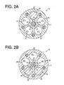
Fig. 2A is a cross-sectional view taken along the line I-I inFig.1 ; -
Fig. 2B is a cross-sectional view taken along the line II-II inFig. 1 ; -
Fig. 3 is a partially enlarged crass-sectional view of the compressor in a disconnecting state according to the first embodiment of the present invention; -
Fig. 4 is a partially enlarged cross-sectional view of the compressor in a connecting state according to the first embodiment of the present invention; -
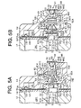
Fig. 5A is a partially enlarged cross-sectional view of a compressor in a disconnecting state according to a second embodiment of the present invention; -
Fig. 5B is a partially enlarged cross-sectional view of the compressor in a connecting state according to the second embodiment of the present invention; -
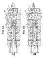
Fig. 6A is a partially enlarged cross-sectional view of a compressor in a connecting state according to a third embodiment of the present invention; -
Fig. 6B is a partially enlarged cross-sectional view of the compressor in a disconnecting state according to the third embodiment of the present invention; -
Fig. 7A is a partially enlarged cross-sectional view of a compressor in a disconnecting state according to a fourth embodiment of the present invention; -
Fig. 7B is a partially enlarged cross-sectional view of the compressor in a connecting state according to the fourth embodiment of the present invention; and -
Fig. 8 is a longitudinal cross-sectional view of a compressor according to a fifth embodiment of the present invention. - The following will describe a first embodiment of the present invention with reference to
Figs. 1 through 4 .Fig. 1 shows apiston type compressor 10 according to the first embodiment. Thecompressor 10 is of a fixed displacement type. It is noted that the left side and right side of thecompressor 10 as viewed inFig. 1 are the front and rear sides thereof, respectively. Referring toFig. 1 , thecompressor 10 has a pair ofcylinder blocks front housing 13 is connected to thecylinder block 11. Arear housing 14 is connected to thecylinder block 12. The cylinder blocks 11, 12, thefront housing 13, and therear housing 14 constitute a housing assembly of thecompressor 10. A discharge chamber 131 as a discharge pressure region in thecompressor 10 is defined in thefront housing 13. Adischarge chamber 141 as the discharge pressure region in thecompressor 10 is defined in therear housing 14. Asuction chamber 142 as a suction pressure region in thecompressor 10 is defined in therear housing 14. It is noted that "in the compressor" used hereinafter is the inside of the housing assembly, and that "out of the compressor" is the outside of the housing assembly. - A valve port plate 15, a
valve plate 16, and aretainer plate 17 are interposed between thecylinder block 11 and thefront housing 13. Avalve port plate 18, avalve plate 19, and aretainer plate 20 are Interposed between thecylinder block 12 and therear housing 14. Thevalve port plates 15, 18 are formed withdischarge ports valve plates discharge valves retainer plates retainers discharge valves - The cylinder blocks 11, 12 rotatably support a
rotary shaft 21. The cylinder blocks 11, 12 are formed withshaft holes rotary shaft 21 is inserted into the shaft holes 111, 121. The outer peripheral surface of therotary shaft 21 is in contact with the inner peripheral surfaces of the shaft holes 111, 121. The cylinder blocks 11, 12 support directly therotary shaft 21 through the inner peripheral surfaces of the shaft holes 111, 121, respectively. The outer peripheral surface of therotary shaft 21 has a sealingsurface 211 in contact with theshaft hole 111 and has a sealingsurface 212 in contact with theshaft hole 121. - The
compressor 10 has aswash plate 23 serving as a cam body and fixed to therotary shaft 21. Theswash plate 23 is accommodated in acrank chamber 24 defined between the cylinder blocks 11, 12. A lip-type seal member 22 is interposed between thefront housing 13 and therotary shaft 21. Theseal member 22 prevents leakage of refrigerant between thefront housing 13 and therotary shaft 21. The front end of therotary shaft 21 protruding out of thefront housing 13 is connected to avehicle engine 26 as an external drive source through anelectromagnetic clutch 25. Therotary shaft 21 receives driving force from thevehicle engine 26 through theelectromagnetic clutch 25. - As shown in
Fig. 2A , thecylinder block 11 is formed with a plurality of cylinder bores 27 arranged around therotary shaft 21. As shown inFig. 2B , thecylinder block 12 is formed with a plurality of cylinder bores 28 arranged around therotary shaft 21. Each cylinder bore 28 of thecylinder block 12 is paired with the opposite cylinder bore 27 of thecylinder block 11. Each pair of cylinder bores 27,28 accommodates therein a double-headedpiston 29. - As shown in
Fig. 1 , the double-headedpiston 29 is coupled to theswash plate 23 through a pair ofshoes 30. Theswash plate 23 rotates integrally with therotary shaft 21. The rotary motion of theswash plate 23 is transmitted to the double-headedpiston 29 through theshoes 30, so that the double-headedpiston 29 reciprocates in the pair of cylinder bores 27, 28. The double-headedpiston 29 definescompression chambers - The
rotary shaft 21 is formed therein with an in-shaft passage 31. The in-shaft passage 31 extends along arotational axis 210 of therotary shaft 21. The in-shaft passage 31 has aninlet 311 andoutlets inlet 311 is formed at anend surface 213 of therotary shaft 21 in thecylinder block 12. Theinlet 311 is open to thesuction chamber 142 in therear housing 14. Theoutlet 312 is open at the sealingsurface 211 of therotary shaft 21 in theshaft hole 111. Theoutlet 313 is open at the sealingsurface 212 of therotary shaft 21 in theshaft hole 121. - As shown in
Fig. 2A , thecylinder block 11 is formed with a plurality ofcommunication passages 32. Eachcommunication passage 32 communicates with the cylinder bore 27 and theshaft hole 111. As shown inFig. 2B , thecylinder block 12 is formed with a plurality ofcommunication passages 33. Eachcommunication passage 33 communicates with the cylinder bore 28 and theshaft hole 121. As therotary shaft 21 rotates, theoutlets shaft passage 31 intermittently communicate with thecommunication passages - When the cylinder bore 27 is in a suction process, that is, the process moving the double-headed
piston 29 rightward inFig. 1 , theoutlet 312 is connected to thecommunication passage 32. Refrigerant in the in-shaft passage 31 of therotary shaft 21 is introduced into thecompression chamber 271 in the cylinder bore 27 through theoutlet 312 and thecommunication passage 32. - When the cylinder bore 27 is in a discharge process, that is, the process moving the double-headed
piston 29 leftward inFig. 1 , theoutlet 312 is disconnected from thecommunication passage 32. Refrigerant in thecompression chamber 271 is discharged into the discharge chamber 131 thorough thedischarge port 151 while pushing open thedischarge valve 181. Refrigerant discharged into the discharge chamber 131 then flows into an externalrefrigerant circuit 34 through apassage 341. - When the cylinder bore 28 is in a suction process, that is, the process moving the double-headed
piston 29 leftward inFig. 1 , theoutlet 313 is connected to thecommunication passage 33. Refrigerant in the in-shaft passage 31 of therotary shaft 21 is introduced into thecompression chamber 281 in the cylinder bore 28 through theoutlet 313 and thecommunication passage 33. - When the cylinder bore 28 is in a discharge process, that is, the process moving the double-headed
piston 29 rightward inFig. 1 , theoutlet 313 is disconnected from thecommunication passage 33. Refrigerant in thecompression chamber 281 is discharged into thedischarge chamber 141 through thedischarge port 181 while pushing open the discharge valve 191.Refrigerant discharged into thedischarge chamber 141 then flows into the externalrefrigerant circuit 34 through apassage 342. - Oil is contained in the
compressor 10 and the externalrefrigerant circuit 34. The oil flows with refrigerant and lubricates various parts requiring lubrication in thecompressor 10. The externalrefrigerant circuit 34 is provided with aheat exchanger 37 for removing heat from refrigerant, an expansion valve 38, and aheat exchanger 39 for evaporating refrigerant with heat. The expansion valve 38 controls the flow rate of refrigerant depending on the change of refrigerant temperature at the outlet of theheat exchanger 39. The refrigerant flowing into the externalrefrigerant circuit 34 then returns to thesuction chamber 142 of thecompressor 14. - The sealing
surface 211 of therotary shaft 21 forms a firstrotary valve 35 and the sealingsurface 212 of therotary shaft 21 forms a secondrotary valve 36. That is, therotary shaft 21 serves as a rotary valve in the present invention. Therotational axis 210 of therotary shaft 21 serves as the rotational axis of the rotary valve. Theend surface 213 of therotary shaft 21, that is, the end surface of the rotary valve, intersects with therotational axis 210 of the rotary valve. Therotary valve compression chambers shaft passage 31 and theoutlets shaft hole 111 serves as a valve chamber accommodating therein the firstrotary valve 35, and theshaft hole 121 serves as a valve chamber accommodating therein the secondrotary valve 36. - As shown in
Figs. 3 and4 , therear housing 14 defining therein thesuction chamber 142 is formed at the rear end thereof with a base 40 integral with therear housing 14. Thebase 40 is formed at aninner surface 401 thereof with acylinder 41 integral with thebase 40. Theinner surface 401 of thebase 40 intersects perpendicularly with therotational axis 210 of therotary shaft 21. - The
cylinder 41 has aninner space 411 receiving therein a slidable spool-shapedvalve body 42. Thevalve body 42 includes a disk-shapedpiston portion 43 and acylindrical portion 44. Thecylindrical portion 44 is formed with anintroduction port 441. Theintroduction port 441 is open at the outer peripheral surface of thecylindrical portion 44 and communicates with aninner space 442 of thecylindrical portion 44. Theinner space 442 serves as an internal passage of thevalve body 42. Thepiston portion 43 defines abackpressure chamber 412 in theinner space 411 of thecylinder 41. Thebackpressure chamber 412 communicates with thesuction chamber 142 through abackpressure passage 413. Thebackpressure passage 413 has aninlet 414 that is disposed above thebackpressure chamber 412. Aflat bottom surface 402 of thebackpressure chamber 412 forms a part of theinner surface 401 of thebase 40. - The
cylinder block 12 is formed at the rear end thereof with aguide 45 having a cylindrical shape and facing to thecylinder 41. Theguide 45 has aninner space 451 communicating with the in-shaft passage 31 through theinlet 311. The rear end of theguide 45 is spaced away from the front end of thecylinder 41. Thecylindrical portion 44 of thevalve body 42 is slidably fitted to theguide 45. Acircular clip 46 is installed in the inner surface of theguide 45. Areturn spring 47 is interposed between thecircular clip 46 and thepiston portion 43. Thereturn spring 47 urges thevalve body 42 in such a direction that thevalve body 42 approaches thebottom surface 402. When thevalve body 42 approaches thebottom surface 402, the volume of thebackpressure chamber 412 decreases. - The
piston portion 43 of thevalve body 42 has a pressure-receivingsurface 431 receiving the pressure in thebackpressure chamber 412. The pressure-receivingsurface 431 is a flat surface and is parallel to thebottom surface 402. The pressure-receivingsurface 431 and thebottom surface 402 are perpendicular to therotational axis 210. The pressure-receivingsurface 431 is contactable with thebottom surface 402. - The base 40 as a rear housing wall is formed with a
bleed passage 48. Thebleed passage 48 is formed inside thebase 40 and extends through thebase 40. Thebleed passage 48 includes avalve port 481, anoutlet passage 482, and avalve chamber 483. Thevalve port 481 is open to thebackpressure chamber 412. Theoutlet passage 482 is open to thesuction chamber 142 at the outlet thereof. Thevalve chamber 483 communicates with thevalve port 481 and theoutlet passage 482. Thevalve port 481 serves as the inlet of thebleed passage 48. - The
valve chamber 483 accommodates therein a ball-shapedvalve body 49 that is operable to open and close thevalve port 481. Thevalve chamber 483 is closed by acover 51 so as to be separated from the outside of thecompressor 10. Acompression spring 50 is disposed between thevalve body 49 and thecover 51 for urging thevalve body 49 in such a direction that thevalve body 49 closes thevalve port 481. Thevalve port 481, thevalve chamber 483, thevalve body 49, and thecompression spring 50 constitute a check valve G1 allowing the fluid to flow from thebackpressure chamber 412 into thebleed passage 48. - In
Fig. 4 , thewhole introduction port 441 faces thesuction chamber 142, so that the in-shaft passage 31 is connected to thesuction chamber 142 through theinner space 451, theinner space 442, and theintroduction port 441. Thevalve body 42 is then placed apart from thebottom surface 402.Fig. 4 shows a state where thevalve body 42 is placed at a connecting position to connect the in-shaft passage 31 to thesuction chamber 142. InFig. 3 , on the other hand, theintroduction port 441 is in theinner space 411 and closed by thecylinder 41 of thebase 40. Therefore, the in-shaft passage 31 is disconnected from thesuction chamber 142. The pressure-receivingsurface 431 of thepiston portion 43 of thevalve body 42 is in surface contact with thebottom surface 402.Fig. 3 shows a state where thevalve body 42 is placed at a disconnecting position to disconnect the in-shaft passage 31 from thesuction chamber 142. The oil in thecompressor 10 flows with refrigerant and collected at the bottom in thebackpressure chamber 412 and in thesuction chamber 142 as indicated by X and Y inFigs. 3 and4 . Some of the oil flowing with refrigerant in thecompressor 10 is attached to the pressure-receivingsurface 431 and thebottom surface 402. InFig. 3 wherein the pressure-receivingsurface 431 is in contact with thebottom surface 402, an oil film due to the oil X is formed between these two surfaces. Such a contact with an oil film is also referred to as "surface contact." - Referring to
Fig. 1 , theelectromagnetic clutch 25 is controlled by a computer C. The computer C is in electrical communication with an operating switch W for an air conditioner, a temperature setting device S for setting a target room temperature, and a temperature detecting device F for detecting a room temperature. When the operating switch W is turned on, the computer C controls the electric supply to the electromagnetic clutch 25 depending on the temperature difference between the target room temperature and the detected room temperature. - The computer C stops the electric supply to the electromagnetic clutch 25 when the detected temperature is below the target temperature, or when the detected temperature is above the target temperature but the temperature difference therebetween is within an allowable range. In this case, the
electromagnetic clutch 25 is disengaged, so that the driving force of thevehicle engine 26 is not transmitted to therotary shaft 21. The computer C allows the electric supply to the electromagnetic clutch 25 when the detected temperature is above the target temperature and the temperature difference is beyond the allowable range. In this case, theelectromagnetic clutch 25 is engaged, so that the driving force of thevehicle engine 26 is transmitted to therotary shaft 21. - When the
piston type compressor 10 is in a stopped state (or theelectromagnetic clutch 25 is disengaged), the pressure in thecompressor 10 is balanced. That is, thevalve body 42 is maintained at the disconnecting position by spring force of thereturn spring 47, as shown inFig. 3 . The pressure-receivingsurface 431 of thevalve body 42 is kept in surface contact with thebottom surface 402 via the above-described oil film. - When the
compressor 10 is started, refrigerant in the in-shaft passage 31 and theinner spaces Fig. 1 ) and thecompression chamber 281. Therefore, the pressure in the in-shaft passage 31 and theinner spaces shaft passage 31 and theinner spaces suction chamber 142. The pressure in thesuction chamber 142 is applied to thebackpressure chamber 412 and, therefore, the pressure in thebackpressure chamber 412 is equivalent to the pressure in thesuction chamber 142. The pressure in thebackpressure chamber 412 acts in opposition to the pressure in theinner spaces return spring 47 through thevalve body 42. - The
piston portion 43 of thevalve body 42 is attached to thebottom surface 402 by adhesive force of the oil film applied between the pressure-receivingsurface 431 and thebottom surface 402. It is so set that the sum of the spring force of thereturn spring 47 and the adhesive force is smaller than the pressure difference between thebackpressure chamber 412 and theinner spaces compressor 10 is started. Accordingly, thevalve body 42 is moved from the disconnecting position ofFig. 3 to the connecting position ofFig. 4 when thecompressor 10 is started. When thevalve body 42 is at the connecting position, refrigerant in thesuction chamber 142 is introduced into the in-shaft passage 31 through theintroduction port 441 and theinner spaces compression chambers communication passages - When the
compressor 10 is stopped, refrigerant in the in-shaft passage 31 and theinner spaces compression chambers shaft passage 31 and theinner spaces backpressure chamber 412. Thevalve body 42 is moved from the connecting position ofFig. 4 to the disconnecting position ofFig. 3 by the spring force of thereturn spring 47. - While the
valve body 42 is moving from the disconnecting position toward the connecting position, the oil in thesuction chamber 142 is introduced into thebackpressure chamber 412 through thebackpressure passage 413. When thevalve body 42 is at the connecting position, as shown inFig. 4 , the oil in thesuction chamber 142 is also introduced into thebackpressure chamber 412 through thebackpressure passage 413. As a result, the oil X is collected in thebackpressure chamber 412. Since the pressure in thebackpressure chamber 412 is equivalent to the pressure in theoutlet passage 482 of thebleed passage 48, thevalve port 481 is kept closed by thevalve body 49 receiving the spring force of thecompression spring 50. Accordingly, the oil Y in thesuction chamber 142 does not flow into thebackpressure chamber 412 through thebleed passage 48. When thecompressor 10 is stopped and thevalve body 42 is returned from the connecting position to the disconnecting position, the oil X in thebackpressure chamber 412 flows out to thesuction chamber 142 through thebackpressure passage 413. The oil X in thebackpressure chamber 412 also flows out to thesuction chamber 142 through thebleed passage 48 while pushing away thevalve body 49 from thevalve port 481. - The
valve body 42 is movable between the connecting position and the disconnecting position depending on pressure variation in the in-shaft passage 31 as thecompressor 10 is started and stopped. Thevalve body 42 placed at the connecting position connects thesuction chamber 142 to theoutlets shaft passage 31. Thevalve body 42 placed at the disconnecting position disconnects thesuction chamber 142 from theoutlets valve body 42, thereturn spring 47, thebackpressure chamber 412, and thebackpressure passage 413 constitute a shiftingdevice 52. The shiftingdevice 52 shifts between a connecting state and a disconnecting state. - In
Fig. 3 , the shiftingdevice 52 is in the disconnecting state where the outlet 312 (seeFig. 1 ) and theoutlet 313 of the in-shaft passage 31 are disconnected from thesuction chamber 142. In other words, the compression chamber 271 (seeFig. 1 ) and thecompression chamber 281 are disconnected from thesuction chamber 142 upstream the shiftingdevice 52 through therotary valves Fig. 4 , the shiftingdevice 52 is in the connecting state where theoutlets suction chamber 142. In other words, thecompression chambers suction chamber 142 upstream the shiftingdevice 52 through therotary valves device 52 corresponds to the connecting and disconnecting positions of thevalve body 42, respectively. - The
piston type compressor 10 according to the first embodiment offers the following advantages. - (1) The amount of refrigerant compressed while the shifting
device 52 is in the disconnecting state is less than that of the background arts. Therefore, a rapid increase in the compressor torque, that is a shock, at the start of thecompressor 10 is further suppressed, as compared to the background arts. - (2) If the
valve body 42 takes a long time to move from the disconnecting position to the connecting position, the shock at the start of thecompressor 10 is effectively suppressed. As described above, the oil film is formed between the pressure-receivingsurface 431 of thevalve body 42 and thebottom surface 402 of thebackpressure chamber 412 when thevalve body 42 is at the disconnecting position. Therefore, in starting thecompressor 10, the time when thevalve body 42 at the disconnecting position starts to move toward the connecting position is delayed because of the adhesive force of the oil film. As a result, the shock at the start of thecompressor 10 is effectively suppressed. - (3) If the oil X in the
backpressure chamber 412 does not flow out of thebackpressure chamber 412, thevalve body 42 cannot be returned to the disconnecting position. If thevalve body 42 is not at the disconnecting position when thecompressor 10 is started, the amount of refrigerant compressed at the start of thecompressor 10 is increased, as compared to a case wherein thevalve body 42 is at the disconnecting position. As a result, the shock at the start of thecompressor 10 may not be sufficiently suppressed.
According to the embodiment, however, when thecompressor 10 is stopped, the oil X in thebackpressure chamber 412 flows out to thesuction chamber 142 through thebackpressure passage 413 and thebleed passage 48 as thevalve body 42 is moved. Thus, thevalve body 42 is reliably returned to the disconnecting position by the spring force of thereturn spring 47. - (4) The pressure-receiving
surface 431 andbottom surface 402 are flat surfaces and are parallel to each other. The pressure-receivingsurface 431 comes into surface contact with thebottom surface 402. According to such structure, an oil film is formed on the wholebottom surface 402 except thevalve port 481 facing thebackpressure chamber 412 when thevalve body 42 is at the disconnecting position. Obviously, such structure maximizes the adhesive force of the oil film. Therefore, the time when thevalve body 42 starts to move from the disconnecting position toward the connecting position is further delayed, and the shock at the start of thecompressor 10 is effectively suppressed. - (5) The oil X collected in the
backpressure chamber 412 flows out to thesuction chamber 142 through thebleed passage 48 as well as through thebackpressure passage 413. Accordingly, the cross sectional area of thebackpressure passage 413 can be minimized in such a range that the pressure in thesuction chamber 142 is applied to thebackpressure chamber 412. Such structure effectively prevents the oil in thesuction chamber 142 from flowing easily into thebackpressure passage 413. - (6) When the
compressor 10 is stopped, thevalve body 42 is returned to the disconnecting position by the spring force of thereturn spring 47. The use of thereturn spring 47 helps to simplify the structure for returning thevalve body 42 to the disconnecting position. - (7) The oil flowing with the refrigerant tends to be collected at the bottom of the
suction chamber 142. According to the embodiment wherein theinlet 414 of thebackpressure passage 413 is disposed above thebackpressure chamber 412, the amount of oil flowing into thebackpressure passage 413 or into thebackpressure chamber 412 is reduced. - (8) The
introduction port 441 serves as an inlet of theinner space 442 of thevalve body 42. When thevalve body 42 is at the disconnecting position, theintroduction port 441 of thevalve body 42 is positioned in theinner space 411 of thecylinder 41, so that the in-shaft passage 31 is closed. When thevalve body 42 is at the connecting position, theintroduction port 441 is positioned out of theinner space 411 and faces thesuction chamber 142, so that the in-shaft passage 31 is open. Such structure permits theintroduction port 441 to be enlarged in size, thereby enabling the in-shaft passage 31 to have an adequate cross sectional area. - The following will describe a second embodiment of the present invention with reference to
Figs. 5A and 5B . The same reference numerals denote the identical components to those in the first embodiment. - The
rear housing 14 is formed with acommunication chamber 53 and avalve port 541. Thecommunication chamber 53 accommodates therein aplate 55 made of a magnetic material and operable to open and close thevalve port 541. Thevalve port 541 is formed through apartition wall 54 separating thecommunication chamber 53 from thesuction chamber 142. Theinlet 311 of the in-shaft passage 31 is formed at theend surface 213 of therotary shaft 21 in thecylinder block 12 and is open to thecommunication chamber 53 in therear housing 14. - A
piston portion 56 is slidably fitted in theinner space 411. Thepiston portion 56 has a pressure-receivingsurface 561 for receiving the pressure in thebackpressure chamber 412. Thepiston portion 56 is formed integrally with arod 67, Therod 57 is fixed at the end thereof to theplate 55. Theplate 55 is contactable at a sealingsurface 551 thereof with avalve seat 542 thereby to close thevalve port 541 and separable from thevalve seat 542 thereby to open thevalve port 541. The sealingsurface 551 is a flat surface. That is, when theplate 55 closes thevalve port 541, the sealingsurface 551 of theplate 55 is in surface contact with thevalve seat 542. Thepiston portion 56, therod 57, and theplate 55 constitute avalve body 59 opening and closing thevalve port 541. Thevalve body 59 defines thebackpressure chamber 412 in theinner space 411. - The
inner surface 401 around thecylinder 41 is formed with aprotrusion 58 having a circular shape in the radial direction of thecompressor 10. Theinlet 414 of thebackpressure passage 413 is open at the end surface of theprotrusion 58. The outer periphery of theprotrusion 58 serves as a steppedportion 581 surrounding circumferentially theinlet 414. - A
return spring 60 is interposed between thepiston portion 56 and thepartition wall 54 for urging thepiston portion 56 into theinner space 411. InFig. 5B , thevalve body 59 opens thevalve port 541 and is at the connecting position to connect thecommunication chamber 53 to thesuction chamber 142. InFig. 5A , thevalve body 59 closes thevalve port 541 and is at the disconnecting position to disconnect thecommunication chamber 53 from thesuction chamber 142. Thereturn spring 60 urges thevalve body 59 toward the disconnecting position. - The
plate 55 is formed with restrictingmembers 552 at the front surface thereof facing theend surface 213 of therotary shaft 21. The restrictingmembers 552 protrude from the front surface of theplate 55. As shown inFigs. 5A and 5B , thecylinder block 12 is formed at anend surface 122 with acylindrical portion 123 protruding therefrom. The restrictingmembers 552 are contactable with and separable from the end of thecylindrical portion 123. When thevalve body 59 is at the connecting position ofFig. 5B , the restrictingmembers 552 are in contact with the end of thecylindrical portion 123. When thevalve body 59 is at the disconnecting position ofFig. 5A , the restrictingmembers 552 are placed apart from the end of thecylindrical portion 123. - When the
piston type compressor 10 is in a stopped state, thevalve body 59 is maintained at the disconnecting position ofFig. 5A by spring force of thereturn spring 60. Refrigerant in thesuction chamber 142 is not introduced into thecommunication chamber 53. The pressure-receivingsurface 561 of thepiston portion 56 is in surface contact with thebottom surface 402. - When the
compressor 10 is started, refrigerant in the in-shaft passage 31 and thecommunication chamber 53 is introduced into the compression chamber 271 (seeFig. 1 ) and thecompression chamber 281. As a result, the pressure in the in-shaft passage 31 and thecommunication chamber 53 decreases. That is, the pressure in the in-shaft passage 31 and thecommunication chamber 53 becomes lower than the pressure in thesuction chamber 142. Accordingly, thevalve body 59 is moved to the connecting position ofFig. 5B and the refrigerant in thesuction chamber 142 flows into thecompression chambers valve port 541, thecommunication chamber 53, and the in-shaft passage 31. - The
valve body 59, thereturn spring 60, thebackpressure chamber 412, and thebackpressure passage 413 constitute ashifting device 52A. The shiftingdevice 52A shifts between the connecting state and the disconnecting state. In the connecting state, thesuction chamber 142 is connected to the outlet 312 (seeFig. 1 ) and theoutlet 313 of the in-shaft passage 31. In the disconnecting state, thesuction chamber 142 is disconnected from theoutlets - In the second embodiment, the volume of the
communication chamber 53 accommodating therein theplate 55 is reduced. That is, the amount of refrigerant compressed in thecompression chambers compressor 10 is suppressed similar to the first embodiment. Additionally, since the steppedportion 581 is provided around theinlet 414 of thebackpressure passage 413, the oil attached to theinner surface 401 around thecylinder 41 hardly enters into thebackpressure passage 413. That is, such structure prevents the oil in thesuction chamber 142 from flowing easily into thebackpressure chamber 412, thereby allowing thevalve body 59 to be returned reliably to the disconnecting position. - The following will describe a third embodiment of the present invention with reference to
Figs. 6A and 6B . The same reference numerals denote the identical components to those in the first embodiment. - A
piston portion 61 is slidably fitted in thecylinder 41. Thepiston portion 61 defines thebackpressure chamber 412 in theinner space 411. Thepiston portion 61 has a pressure-receivingsurface 611 for receiving the pressure in thebackpressure chamber 412. Thepiston portion 61 is connected to arod 62 that is inserted in an in-shaft passage 31A of therotary shaft 21. The in-shaft passage 31 A as the supply passage of the rotary valve includes a small-diameter passage 314 and a large-diameter passage 315. Adisk 63 is fixed to the end of therod 62 in the small-diameter passage 314. Acylindrical member 64 is fixed to therod 62 in the large-diameter passage 315. - The
disk 63 is fitted in the small-diameter passage 314 so as to be slidable in the direction of therotational axis 210 of therotary shaft 21. Thecylindrical member 64 is fitted in the large-diameter passage 315 so as to be slidable in the direction of therotational axis 210 thereby to open and close theoutlet 313 in the large-diameter passage 315. A region of the in-shaft passage 31A between thedisk 63 and thecylindrical member 64 communicates with a region of the in-shaft passage 31A between theinlet 311 and thecylindrical member 64 through the inner space of thecylindrical member 64. - As shown in
Fig. 6B , when thecylindrical member 64 closes theoutlet 313, thedisk 63 is placed rearward of theoutlet 312 in the in-shaft passage 31A. As a result, refrigerant in the in-shaft passage 31A is not introduced into the compression chamber 271 (seeFig. 1 ) through theoutlet 312. As shown inFig. 6A , when thecylindrical member 64 opens theoutlet 313, thedisk 63 is placed forward of theoutlet 312 in the in-shaft passage 31A. As a result, refrigerant in the in-shaft passage 31A is introduced into thecompression chamber 271 through theoutlet 312. - The in-
shaft passage 31A is formed with astep 316 between the small-diameter passage 314 and the large-diameter passage 315. Areturn spring 65 is interposed between thestep 316 and thecylindrical member 64. Thereturn spring 65 urges thedisk 63, thecylindrical member 64, therod 62, and thepiston portion 61 together toward thebackpressure chamber 412, that is, in the direction that causes thepiston portion 61 to be pushed into theinner space 411. - The ball-shaped
valve body 49 is accommodated in avalve chamber 483A. Thevalve chamber 483A constitutes ableed passage 48A. Thevalve body 49 closes avalve port 481A by own weight thereof. Thevalve port 481A, thevalve chamber 483A, and thevalve body 49 constitute a check valve G2. The check valve G2 allows the fluid to flow from thebackpressure chamber 412 into thebleed passage 48A. - The
inlet 414 of thebackpressure passage 413 is open at theinner surface 401 around thecylinder 41. Theinner surface 401 is formed with anannular groove 66 surrounding circumferentially theinlet 414. The inner periphery of thegroove 66 serves as a steppedportion 661. - When the
compressor 10 is in a stopped state, thedisk 63 and thecylindrical member 64 are maintained at the disconnecting position shown inFig. 6B by spring force of thereturn spring 65. The pressure-receivingsurface 611 of thepiston portion 61 is then in surface contact with thebottom surface 402. - When the
compressor 10 is started, refrigerant in a space 317 (a part of the in-shaft passage 31A) formed between thedisk 63 and the front end of the in-shaft passage 31A is introduced into the compression chamber 271 (seeFig. 1 ). Accordingly, the pressure in thespace 317 decreases, and thedisk 63 and thecylindrical member 64 are moved from the disconnecting position ofFig. 6B to the connecting position ofFig. 6A against the spring force of thereturn spring 65. - When the
compressor 10 is stopped, thedisk 63 and thecylindrical member 64 are returned to the disconnecting position ofFig. 6B by the spring force of thereturn spring 65. The oil collected in thebackpressure chamber 412 flows out to thesuction chamber 142 through thebleed passage 48A while pushing away thevalve body 49 from thevalve port 481A. - The
disk 63, thecylindrical member 64, therod 62, and thepiston portion 61 constitute avalve body 100 defining thebackpressure chamber 412 in theinner space 411. Thevalve body 100 is movable between the connecting position and the disconnecting position depending on pressure variation in thespace 317 as thecompressor 10 is started and stopped. Thevalve body 100 at the connecting position connects theoutlets shaft passage 31A to thesuction chamber 142 in thecompressor 10. Thevalve body 100 at the disconnecting position disconnects theoutlets suction chamber 142. Thevalve body 100, thereturn spring 65, thebackpressure chamber 412, and thebackpressure passage 413 constitute ashifting device 52B. The shiftingdevice 52B shifts between the connecting state and the disconnecting state. In the connecting state, theoutlets shaft passage 31A are connected to thesuction chamber 142 in thecompressor 10. In the disconnecting state, theoutlets suction chamber 142. - The third embodiment offers further advantages in addition to the aforementioned advantages of the first and the second embodiments. Specifically, the third embodiment is more complicated in structure, but the shock at the start of the
compressor 10 is suppressed, as compared to the first and the second embodiments. This is because only the refrigerant in thespace 317, theoutlets communication passages compression chambers disk 63 and thecylindrical member 64 are placed at the disconnecting position. - Further, the structure of the check valve G2 is simplified, as compared to that of the check valve G1 in the first and second embodiments, because the
valve body 49 closes thevalve port 481A by own weight thereof. Additionally, the oil attached to theinner surface 401 around thecylinder 41 hardly enters into thebackpressure passage 413 because the steppedportion 661 is provided around theinlet 414 of thebackpressure passage 413. That is, such structure prevents the oil in thesuction chamber 142 from flowing easily into thebackpressure chamber 412. - The following will describe a fourth embodiment of the present invention with reference to
Figs. 7A and 7B . The same reference numerals denote the identical components to those in the first embodiment. - The
piston portion 43 has acylindrical portion 67 on the back of the pressure-receivingsurface 431. Thecylindrical portion 67 defines therein a valve chamber 671. The ball-shapedvalve body 49 is accommodated in the valve chamber 671. Thepiston portion 43 is formed with avalve port 432 that is open at the pressure-receivingsurface 431. Acircular clip 68 is installed in the inner surface of thecylindrical portion 67. Thecompression spring 50 is disposed in the valve chamber 671 between thecircular clip 68 and thevalve body 49. Thevalve body 49 is operable to open and close thevalve port 432. Thecompression spring 50 urges thevalve body 49 in such a direction that thevalve body 49 closes thevalve port 432. The valve chamber 671 communicates with theinner space 442 of thecylindrical portion 44. The valve chamber 671 and thevalve port 432 constitute ableed passage 69. Thevalve port 432, the valve chamber 671, thevalve body 49, and thecompression spring 50 constitute a check valve G3 allowing the fluid to flow from thebackpressure chamber 412 into thebleed passage 69. - When the
compressor 10 is in a stopped state, thevalve body 42 is maintained at the disconnecting position shown inFig. 7A by spring force of thereturn spring 47. The pressure-receivingsurface 431 is in surface contact with thebottom surface 402, and the oil film is formed between the pressure-receivingsurface 431 and thebottom surface 402. - When the
compressor 10 is started, thevalve body 42 is moved from the disconnecting position ofFig. 7A to the connecting position shown inFig. 7B against the sum of the spring force of thereturn spring 47 and the adhesive force of the oil film. - When the
compressor 10 is stopped, thevalve body 42 is returned to the disconnecting position ofFig. 7A by the spring force of thereturn spring 47. The oil collected in thebackpressure chamber 412 flows out through thebleed passage 69 into theinner space 442 while pushing thevalve body 49 away from thevalve port 432. - The fourth embodiment offers the advantages similar to those of the first embodiment.
- The following will describe a fifth embodiment of the present invention with reference to
Fig. 8 . The same reference numerals denote the identical components to those in the first embodiment. - A housing assembly of a
piston type compressor 10A includes thecylinder block 12, thefront housing 13, and therear housing 14. Thecompressor 10A is of a fixed displacement type. Thecrank chamber 24 is defined between thecylinder block 12 and thefront housing 13 and accommodates therein theswash plate 23. A single-headedpiston 70 is coupled to theswash plate 23 and reciprocates in the cylinder bore 28 with the rotation of theswash plate 23. Therotary shaft 21 is formed with therotary valve 36 adjacent to thecylinder block 12. Therear housing 14 is formed with thebleed passage 48 and the check valve G1. Thevalve body 42 is received in therear housing 14. - The fifth embodiment offers the advantages similar to those of the first embodiment.
- The above embodiment may be modified in various ways as exemplified below.
- The
rotary valves rotary shaft 21. - An inlet of the bleed passage may be open at the bottom portion of the
backpressure chamber 412. - In the first embodiment, the pressure-receiving
surface 431 may be formed with a concave conical surface, and thebottom surface 402 may be formed with a convex conical surface. In this case, the convex conical surface of thebottom surface 402 is complementary to the concave conical surface of the pressure-receivingsurface 431 so that the twosurfaces surface 431 to be in surface contact with thebottom surface 402 over a larger contact area, with the result that the adhesive force of the oil film therebetween is further increased. - Therefore, the present examples and embodiments are to be considered as illustrative and not restrictive, and the invention is not to be limited to the details given herein but may be modified within the scope of the appended claims.
- A suction structure allows refrigerant from a suction pressure region in a piston type compressor. The suction structure includes a shifting device, a bleed passage, and a check valve. The shifting device has a valve body, a return spring, a backpressure chamber, and a backpressure passage. The valve body is movable between a connecting position and a disconnecting position. The return spring urges the valve body from the connecting position toward the disconnecting position. The backpressure chamber is defined by the valve body. The backpressure passage communicates with the suction pressure region and the backpressure chamber. The bleed passage communicates with the suction pressure region and the backpressure chamber. The check valve allows a fluid to flow from the backpressure chamber into the bleed passage.
Claims (13)
- A suction structure for allowing refrigerant from a suction pressure region (142) in a piston type compressor (10), wherein cylinder bores (27, 28) for accommodating a respective piston (29) are arranged around a rotary shaft (21), wherein the piston (29) is coupled to the rotary shaft (21) through a cam body (23) so that the rotation of the rotary shaft (21) is transmitted to the piston (29), wherein a compression chamber (271, 281) is defined by the piston (29) in the respective cylinder bore (27, 28), wherein a valve mechanism (35, 36) is disposed adjacent to the compression chamber (271, 281),
characterized by the suction structure further comprising:a shifting device (52) for shifting between a connecting state and a disconnecting state, wherein in the connecting state the compression chamber (271, 281) is connected to the suction pressure region (142) upstream the shifting device (52) through the valve mechanism (35, 36), and in the disconnecting state the compression chamber (271, 281) is disconnected from the suction pressure region (142) upstream the shifting device (52) through the valve mechanism (35, 36), the shifting device (52) including;
a valve body (42) movable between a connecting position and a disconnecting position, wherein the connecting position corresponds to the connecting state and the disconnecting position corresponds to the disconnecting state;
a return spring (47) urging the valve body (42) from the connecting position toward the disconnecting position;
a backpressure chamber (412) defined by the valve body (42); and
a backpressure passage (413) communicating with the suction pressure region (142) and the backpressure chamber (412),a bleed passage (48) communicating with the suction pressure region (142) and the backpressure chamber (412); anda check valve (G1) allowing a fluid to flow from the backpressure chamber (412) into the bleed passage (48). - The suction structure according to claim 1, wherein the valve mechanism (35, 36) is a rotary valve (35, 36) rotated integrally with the rotary shaft (21), wherein the rotary valve (35, 36) has a supply passage (31) for introducing the refrigerant from the suction pressure region (142) to the compression chamber (271,281), wherein the supply passage (31) has an outlet (312, 313) and an inlet (311), wherein in the connecting state the suction pressure region (142) is connected to the outlet (312, 313) of the supply passage (31), and in the disconnecting state the suction pressure region (142) is disconnected from the outlet (312, 313) of the supply passage (31).
- The suction structure according to claim 2, wherein the valve body (42) includes a piston portion (43) defining the backpressure chamber (412), the backpressure chamber (412) has a bottom surface (402), and the piston portion (43) has a pressure-receiving surface (431) receiving a pressure in the backpressure chamber (412) and coming into surface contact with the bottom surface (402) of the backpressure chamber (412).
- The suction structure according to claim 3, wherein the pressure-receiving surface (431) and the bottom surface (402) are flat and parallel to each other.
- The suction structure according to claim 3 or claim 4, wherein the bleed passage (48) has an inlet (481) that is open at the bottom surface (402) of the backpressure chamber (492).
- The suction structure according to claim 5, wherein the valve body (42) is moved in axial direction of the rotary shaft (21) between the connecting position and the disconnecting position.
- The suction structure according to any one of claims 1 through 6, wherein the compressor (10) includes a rear housing (14) defining the suction pressure region (142) and having a rear housing wall (40), and the bleed passage (48) is formed inside the rear housing wall (40) so as to communicate with the suction pressure region (142).
- The suction structure according to any one of claims 1 through 7, wherein the backpressure passage (413) has an inlet (414) disposed above the backpressure chamber (412).
- The suction structure according to any one of claims 1 through 8, wherein the backpressure passage (413) has an inlet (414) surrounded circumferentially by a stepped portion (581) in the suction pressure region (142).
- The suction structure according to any one of claims 1 through 9, wherein the valve body (42) is placed so that the inlet (311) of the supply passage (31) is disconnected from the suction pressure region (142) when the shifting device (52) is in the disconnecting state.
- The suction structure according to any one of claims 1 through 10, wherein the compressor (10) includes a cylinder block (12) and a rear housing (14), the cylinder block (12) is formed with the cylinder bores (28), the rear housing (14) is connected to the cylinder block (12) and formed with a suction chamber (142) as the suction pressure region, and the valve body (42) is provided in the rear housing (14).
- The suction structure according to any one of claims 1 through 11, wherein the supply passage has an in-shaft passage (31) formed inside the rotary shaft (21) and extending in axial direction of the rotary shaft (21), the inlet (311) of the supply passage is open at an end surface (213) of the rotary valve (21) and communicating with the in-shaft passage (31), the outlet (312, 313) of the supply passage is open at an outer periphery (211, 212) of the rotary valve (35, 36) and communicating with the in-shaft passage (31), the valve body (100) is disposed in the in-shaft passage (31), the valve body (100) is movable in the axial direction of the rotary shaft (21) between the connecting position and the disconnecting position in the in-shaft passage (31), and the valve body (100) at the disconnecting position disconnects the outlet (312, 313) of supply passage from the in-shaft passage (31).
- The suction structure according to any one of claims 1 through 12, wherein the rotary shaft (21) is coupled to an external drive source (26) through a clutch (25).
Applications Claiming Priority (1)
| Application Number | Priority Date | Filing Date | Title |
|---|---|---|---|
| JP2007229239A JP2009062834A (en) | 2007-09-04 | 2007-09-04 | Coolant intake structure of fixed capacity type piston compressor |
Publications (1)
| Publication Number | Publication Date |
|---|---|
| EP2034183A2 true EP2034183A2 (en) | 2009-03-11 |
Family
ID=40090002
Family Applications (1)
| Application Number | Title | Priority Date | Filing Date |
|---|---|---|---|
| EP08163561A Withdrawn EP2034183A2 (en) | 2007-09-04 | 2008-09-03 | Suction structure in piston type compressor |
Country Status (5)
| Country | Link |
|---|---|
| US (1) | US20090142210A1 (en) |
| EP (1) | EP2034183A2 (en) |
| JP (1) | JP2009062834A (en) |
| CN (1) | CN101382127A (en) |
| BR (1) | BRPI0805053A2 (en) |
Families Citing this family (6)
| Publication number | Priority date | Publication date | Assignee | Title |
|---|---|---|---|---|
| JP2009024558A (en) * | 2007-07-18 | 2009-02-05 | Toyota Industries Corp | Coolant suction structure of fixed displacement piston type compressor |
| JP4924464B2 (en) * | 2008-02-05 | 2012-04-25 | 株式会社豊田自動織機 | Swash plate compressor |
| JP5240311B2 (en) * | 2011-03-15 | 2013-07-17 | 株式会社豊田自動織機 | Cylinder block of piston type compressor and cylinder block processing method of piston type compressor |
| KR101915968B1 (en) * | 2012-04-27 | 2018-11-07 | 한온시스템 주식회사 | Swash plate type compressor |
| JP7151037B2 (en) * | 2018-03-30 | 2022-10-12 | 株式会社豊田自動織機 | piston compressor |
| JP7230762B2 (en) * | 2019-10-02 | 2023-03-01 | 株式会社豊田自動織機 | piston compressor |
Citations (5)
| Publication number | Priority date | Publication date | Assignee | Title |
|---|---|---|---|---|
| JPS6488064A (en) | 1987-09-30 | 1989-04-03 | Hitachi Ltd | Refrigerant circuit for water cooler and heater |
| JPH07119631A (en) | 1993-08-26 | 1995-05-09 | Nippondenso Co Ltd | Swash plate type variable displacement compressor |
| JPH07139474A (en) | 1993-11-17 | 1995-05-30 | Toyota Autom Loom Works Ltd | Starting load reduction device for compressor |
| JP2000145629A (en) | 1998-11-11 | 2000-05-26 | Tgk Co Ltd | Variable displacement compressor |
| JP2006083835A (en) | 2004-09-17 | 2006-03-30 | Toyota Industries Corp | Piston compressor |
Family Cites Families (12)
| Publication number | Priority date | Publication date | Assignee | Title |
|---|---|---|---|---|
| US2899941A (en) * | 1959-08-18 | Fluid motor | ||
| US4874066A (en) * | 1987-12-04 | 1989-10-17 | S.U.I. Corporation | Variable flow shock absorber and method |
| US5207563A (en) * | 1991-05-20 | 1993-05-04 | Kabushiki Kaisha Toyoda Jidoshokki Seisakusho | Swash plate type compressor with a central discharge passage |
| US5478212A (en) * | 1992-03-04 | 1995-12-26 | Nippondenso Co., Ltd. | Swash plate type compressor |
| US5452994A (en) * | 1994-02-16 | 1995-09-26 | Thermo King Corporation | Refrigerant compressor |
| US5572974A (en) * | 1995-02-21 | 1996-11-12 | Siemens Automotive Corporation | Combined start bypass and safety pressure relief valve for a fuel system |
| JPH10325393A (en) * | 1997-05-26 | 1998-12-08 | Zexel Corp | Variable displacement swash plate type clutchless compressor |
| DE19747851A1 (en) * | 1997-10-30 | 1999-05-06 | Bosch Gmbh Robert | Piston pump |
| US6622751B1 (en) * | 1998-02-09 | 2003-09-23 | Continental Teves Ag & Co., Ohg | Pressure valve for a reciprocating pump |
| ATE454986T1 (en) * | 2001-11-12 | 2010-01-15 | Seiko Epson Corp | FLUID INJECTION DEVICE |
| JP3698096B2 (en) * | 2001-11-29 | 2005-09-21 | 株式会社豊田自動織機 | Rotating machinery for vehicles |
| JP4492653B2 (en) * | 2007-08-09 | 2010-06-30 | 株式会社デンソー | Fuel injection valve charging control device and fuel injection valve charging control system |
-
2007
- 2007-09-04 JP JP2007229239A patent/JP2009062834A/en active Pending
-
2008
- 2008-09-02 US US12/231,488 patent/US20090142210A1/en not_active Abandoned
- 2008-09-03 BR BRPI0805053-8A patent/BRPI0805053A2/en not_active IP Right Cessation
- 2008-09-03 CN CNA2008101475835A patent/CN101382127A/en active Pending
- 2008-09-03 EP EP08163561A patent/EP2034183A2/en not_active Withdrawn
Patent Citations (5)
| Publication number | Priority date | Publication date | Assignee | Title |
|---|---|---|---|---|
| JPS6488064A (en) | 1987-09-30 | 1989-04-03 | Hitachi Ltd | Refrigerant circuit for water cooler and heater |
| JPH07119631A (en) | 1993-08-26 | 1995-05-09 | Nippondenso Co Ltd | Swash plate type variable displacement compressor |
| JPH07139474A (en) | 1993-11-17 | 1995-05-30 | Toyota Autom Loom Works Ltd | Starting load reduction device for compressor |
| JP2000145629A (en) | 1998-11-11 | 2000-05-26 | Tgk Co Ltd | Variable displacement compressor |
| JP2006083835A (en) | 2004-09-17 | 2006-03-30 | Toyota Industries Corp | Piston compressor |
Also Published As
| Publication number | Publication date |
|---|---|
| BRPI0805053A2 (en) | 2010-07-27 |
| CN101382127A (en) | 2009-03-11 |
| US20090142210A1 (en) | 2009-06-04 |
| JP2009062834A (en) | 2009-03-26 |
Similar Documents
| Publication | Publication Date | Title |
|---|---|---|
| US7972119B2 (en) | Variable displacement compressor | |
| JP6477441B2 (en) | Variable capacity swash plate compressor | |
| US20040197204A1 (en) | Variable displacement mechanism for scroll type compressor | |
| US9010138B2 (en) | Variable displacement compressor | |
| US20090129948A1 (en) | Suction structure in fixed displacement piston type compressor | |
| US20090142210A1 (en) | Suction structure in piston type compressor | |
| EP2728187B1 (en) | Piston-type compressor | |
| US5562425A (en) | Gas suction structure in piston type compressor | |
| US20020018722A1 (en) | Variable displacement compressor | |
| US7658081B2 (en) | Structure for sensing refrigerant flow rate in a compressor | |
| KR101645276B1 (en) | Variable displacement swash plate type compressor | |
| EP1811177A2 (en) | Structure for oil recovery in a compressor | |
| US20090022604A1 (en) | Suction structure in piston type compressor | |
| EP1712791A2 (en) | Swash plate compressor | |
| JP2014118922A (en) | Variable displacement swash plate type compressor | |
| KR20080044170A (en) | compressor | |
| JP2016169700A (en) | Variable displacement compressor | |
| WO2007086261A1 (en) | Variable displacement-type clutchless compressor | |
| JP3666170B2 (en) | Swash plate compressor | |
| EP3896284B1 (en) | Swash plate compressor | |
| US20090257890A1 (en) | Oil separating structure of variable displacement compressor | |
| JP2017150315A (en) | Variable displacement swash plate compressor | |
| JPH06249144A (en) | Refrigerant gas suction construction of reciprocating compressor | |
| JP2018150880A (en) | Variable displacement swash plate compressor | |
| JP2013204559A (en) | Tandem vane compressor |
Legal Events
| Date | Code | Title | Description |
|---|---|---|---|
| PUAI | Public reference made under article 153(3) epc to a published international application that has entered the european phase |
Free format text: ORIGINAL CODE: 0009012 |
|
| 17P | Request for examination filed |
Effective date: 20080903 |
|
| AK | Designated contracting states |
Kind code of ref document: A2 Designated state(s): AT BE BG CH CY CZ DE DK EE ES FI FR GB GR HR HU IE IS IT LI LT LU LV MC MT NL NO PL PT RO SE SI SK TR |
|
| AX | Request for extension of the european patent |
Extension state: AL BA MK RS |
|
| STAA | Information on the status of an ep patent application or granted ep patent |
Free format text: STATUS: THE APPLICATION IS DEEMED TO BE WITHDRAWN |
|
| 18D | Application deemed to be withdrawn |
Effective date: 20110401 |