EP2034139A2 - Camshaft phaser having pre-loaded spring for biasing the rotor through only a part of its total shifting range. - Google Patents
Camshaft phaser having pre-loaded spring for biasing the rotor through only a part of its total shifting range. Download PDFInfo
- Publication number
- EP2034139A2 EP2034139A2 EP08163298A EP08163298A EP2034139A2 EP 2034139 A2 EP2034139 A2 EP 2034139A2 EP 08163298 A EP08163298 A EP 08163298A EP 08163298 A EP08163298 A EP 08163298A EP 2034139 A2 EP2034139 A2 EP 2034139A2
- Authority
- EP
- European Patent Office
- Prior art keywords
- rotor
- tang
- spring
- stator
- Prior art date
- Legal status (The legal status is an assumption and is not a legal conclusion. Google has not performed a legal analysis and makes no representation as to the accuracy of the status listed.)
- Withdrawn
Links
Images


Classifications
-
- F—MECHANICAL ENGINEERING; LIGHTING; HEATING; WEAPONS; BLASTING
- F01—MACHINES OR ENGINES IN GENERAL; ENGINE PLANTS IN GENERAL; STEAM ENGINES
- F01L—CYCLICALLY OPERATING VALVES FOR MACHINES OR ENGINES
- F01L1/00—Valve-gear or valve arrangements, e.g. lift-valve gear
- F01L1/34—Valve-gear or valve arrangements, e.g. lift-valve gear characterised by the provision of means for changing the timing of the valves without changing the duration of opening and without affecting the magnitude of the valve lift
- F01L1/344—Valve-gear or valve arrangements, e.g. lift-valve gear characterised by the provision of means for changing the timing of the valves without changing the duration of opening and without affecting the magnitude of the valve lift changing the angular relationship between crankshaft and camshaft, e.g. using helicoidal gear
- F01L1/3442—Valve-gear or valve arrangements, e.g. lift-valve gear characterised by the provision of means for changing the timing of the valves without changing the duration of opening and without affecting the magnitude of the valve lift changing the angular relationship between crankshaft and camshaft, e.g. using helicoidal gear using hydraulic chambers with variable volume to transmit the rotating force
-
- F—MECHANICAL ENGINEERING; LIGHTING; HEATING; WEAPONS; BLASTING
- F01—MACHINES OR ENGINES IN GENERAL; ENGINE PLANTS IN GENERAL; STEAM ENGINES
- F01L—CYCLICALLY OPERATING VALVES FOR MACHINES OR ENGINES
- F01L1/00—Valve-gear or valve arrangements, e.g. lift-valve gear
- F01L1/34—Valve-gear or valve arrangements, e.g. lift-valve gear characterised by the provision of means for changing the timing of the valves without changing the duration of opening and without affecting the magnitude of the valve lift
- F01L1/344—Valve-gear or valve arrangements, e.g. lift-valve gear characterised by the provision of means for changing the timing of the valves without changing the duration of opening and without affecting the magnitude of the valve lift changing the angular relationship between crankshaft and camshaft, e.g. using helicoidal gear
- F01L1/3442—Valve-gear or valve arrangements, e.g. lift-valve gear characterised by the provision of means for changing the timing of the valves without changing the duration of opening and without affecting the magnitude of the valve lift changing the angular relationship between crankshaft and camshaft, e.g. using helicoidal gear using hydraulic chambers with variable volume to transmit the rotating force
- F01L2001/3445—Details relating to the hydraulic means for changing the angular relationship
- F01L2001/34453—Locking means between driving and driven members
- F01L2001/34463—Locking position intermediate between most retarded and most advanced positions
-
- F—MECHANICAL ENGINEERING; LIGHTING; HEATING; WEAPONS; BLASTING
- F01—MACHINES OR ENGINES IN GENERAL; ENGINE PLANTS IN GENERAL; STEAM ENGINES
- F01L—CYCLICALLY OPERATING VALVES FOR MACHINES OR ENGINES
- F01L1/00—Valve-gear or valve arrangements, e.g. lift-valve gear
- F01L1/34—Valve-gear or valve arrangements, e.g. lift-valve gear characterised by the provision of means for changing the timing of the valves without changing the duration of opening and without affecting the magnitude of the valve lift
- F01L1/344—Valve-gear or valve arrangements, e.g. lift-valve gear characterised by the provision of means for changing the timing of the valves without changing the duration of opening and without affecting the magnitude of the valve lift changing the angular relationship between crankshaft and camshaft, e.g. using helicoidal gear
- F01L1/3442—Valve-gear or valve arrangements, e.g. lift-valve gear characterised by the provision of means for changing the timing of the valves without changing the duration of opening and without affecting the magnitude of the valve lift changing the angular relationship between crankshaft and camshaft, e.g. using helicoidal gear using hydraulic chambers with variable volume to transmit the rotating force
- F01L2001/3445—Details relating to the hydraulic means for changing the angular relationship
- F01L2001/34483—Phaser return springs
Definitions
- the present invention relates to phasers for varying the phase of valving with respect to a crankshaft in an internal combustion engine; more particularly, to such a phaser employing a spring for biasing the rotational position of a phaser rotor with respect to an associated phaser stator through at least a portion of the rotor range of authority; and most particularly, to such a phaser wherein a pre-loaded bias spring is active through only a portion of the range of authority of rotor rotation.
- Camshaft phasers for varying the timing of combustion valves in an internal combustion engine transmit crankshaft torque to the engine camshaft, allowing varied timing of the camshaft relative to the crankshaft position.
- intake phasers have authority to only advance this timing from their locked position.
- cam torque and the available oil pressure are used to drive the rotor to the fully retarded position where a lock pin in the rotor aligns with a seat in the stator.
- oil pressure drops below the retraction pressure for the lock pin and the pin's bias spring urges the pin to move into engagement with its seat, preventing undesired phase angle changes until sufficient oil pressure is again available.
- Phasers requiring an intermediate lock pin position between full rotor advance and full rotor retard cannot rely on the contract between the rotor and stator to realign the lock pin to its seat. Therefore, when oil pressure is low, some form of assistance is needed to advance the rotor away from full retard to align the lock pin to the seat at the intermediate rotor position. If the assistance were torque from a simple spring-arm system, the bias spring would cause the phaser to advance the rotor through the entire range of rotor authority and past the point where the lock pin aligns with its seat when resistive torque through the phaser system from the camshaft was less than the applied spring torque.
- the invention uses an applied torque between a phaser cover plate, mounted to the stator/sprocket, and phaser rotor to assist in aligning a lock pin to a seat in the stator at an intermediate position in the rotor range of authority.
- the bias spring is captured and guided by a spring retainer that is fitted or formed into the cover.
- the spring retainer allows the bias spring to be installed into the cover in its pre-load position and to be conveniently retained therein as both the grounded and active legs are captured in separate slot features in the spring retainer.
- This sub-assembly cover, retainer, bias spring
- a pocket within the rotor receives the active leg of the bias spring extending from the spring retainer.
- the rotor pocket preferably has a tapered bottom face (ramp) that lifts the active leg of the bias spring off the axial slot wall in the spring retainer and locates the active leg against the wall of the rotor pocket when the rotor moves from the locked position in a retarding direction. Lifting the active tang of the bias spring removes any friction between the bias spring and the retainer slot wall that would occur as the rotor moves in a retarded direction from its intermediate locked position.
- the bias spring's rotation stops when the active tang contacts the end of the spring retainer slot. Contact between the active tang of the bias spring and the end of the slot in the spring retainer removes spring torque that otherwise would bias further advancement of the rotor. This permits the rotor to self-align to its locking position when oil pressure is removed during engine shut down or stall.
- the spring would tip from axial alignment within the phaser and would continue to make contact with the bottom of the pocket in the rotor, creating frictional drag on the rotor as the rotor advances from the locking position.
- the features of the invention therefore serve two purposes: easing phaser assembly, thus reducing cost and improving safety; and eliminating unwanted friction between the bias spring and rotor, thus improving performance and durability.
- a vane-type camshaft phaser 10 in accordance with the invention comprises a driving element 12 in the form of a sprocket wheel integral with a stator 14 having a plurality of inward-extending lobes 16.
- driving element 12 may take the form, as is known in the art, of a notched wheel for receiving a toothed timing belt or a gear for meshing with a timing gear.
- a bottom plate 18 forms a first wall of chambers formed within stator 14 between lobes 16.
- a rotor 20 having four vanes 22a-d is disposed for rotation within stator 14 in known fashion.
- Rotor 20 has at least one, and preferably two, lock pins assemblies 24 hydraulically extendable to engage seats 26 in a cover plate 28 for rotationally locking the rotor to the stator as may be desired.
- Cover plate 28 defines a second wall of the chambers in stator 14.
- Binder screws 30 extend through bottom plate 18 and stator 14, and are threadedly received in cover plate 28.
- a thrust washer 31 is disposed against the hub of rotor 20 for receiving a camshaft-mounting bolt (not shown) during assembly of engine 33.
- a spring retainer 32 receives a helical bias spring 34 having first and second radially-extending tangs 36,38.
- First tang 36 is grounded in a first axial slot 40 formed in the wall of spring retainer 32 and is defined herein as the "inactive" tang.
- Second tang 38 is grounded in a second slot 42 formed in the wall of spring retainer 32 and is defined herein as the "active" tang.
- Second slot 42 preferably includes an axial entry portion and a circumferential portion permitting rotation of second tang 38 during operation of the phaser.
- Spring retainer 32 extends through an opening 44 in cover plate 28 and includes a collar 46 that grounds against the outer surface 48 of cover plate 28 during assembly.
- a notch 50 is provided in the rim of opening 44 for receiving first tang 36 extending beyond the wall of spring retainer 32.
- retainer 32 may be formed into the cover such as, for example, by casting.
- bias spring 34 is captured and guided by spring retainer 32 that is press fit or formed into cover plate 28 with first slot 40 aligned with notch 50.
- first tang 36 is inserted into slot 40 to a depth until second tang 38 engages the end of spring retainer 32.
- Bias spring 34 is then wound until second tang 38 aligns with second slot 42; the spring is then pushed further into spring retainer 32 and then released, thus the spring is captured at a pre-load position, creating subassembly 52.
- the spring retainer allows the bias spring to be installed into the cover in its pre-load position and to be conveniently retained therein as both the inactive and active tangs are captured in separate slot features in the spring retainer.
- Subassembly 52 is then attached by binder screws 30 to the remaining phaser components to complete the full phaser assembly 10.
- An annular well 54 in rotor 20 receives the portion of subassembly 52 extending beyond cover plate 28.
- a pocket 56 within the rotor and outboard of well 54 receives active tang 38 and preferably has a tapered bottom face defining a ramp 58.
- Ramp 58 extends angularly across the lower wall 60 of second slot 42 and receives active tang 38 as spring 34 is torsionally actuated by rotation of rotor 20.
- rotor ramp 58 lifts active tang 38 off the lower slot wall 60 (hidden in FIG. 5 ) and positions tang 38 against a first end wall 62 of rotor pocket 56. Lifting the active tang of the bias spring removes any friction between the spring tang and the slot wall that would otherwise occur as the rotor moves in a retarded direction toward a full retarded authority position from its intermediate position.
- the present invention has been described above in terms of a novel camshaft phaser being applied to an intake valve camshaft and biasing the rotor in the advance direction from retard positions.
- the disclosed invention is not so limited and may be applied to exhaust valve camshafts as well as to biasing the rotor in the retard direction from advanced positions as may be desired.
Landscapes
- Engineering & Computer Science (AREA)
- Mechanical Engineering (AREA)
- General Engineering & Computer Science (AREA)
- Valve Device For Special Equipments (AREA)
- Valve-Gear Or Valve Arrangements (AREA)
Abstract
Description
- The present invention relates to phasers for varying the phase of valving with respect to a crankshaft in an internal combustion engine; more particularly, to such a phaser employing a spring for biasing the rotational position of a phaser rotor with respect to an associated phaser stator through at least a portion of the rotor range of authority; and most particularly, to such a phaser wherein a pre-loaded bias spring is active through only a portion of the range of authority of rotor rotation.
- Camshaft phasers for varying the timing of combustion valves in an internal combustion engine transmit crankshaft torque to the engine camshaft, allowing varied timing of the camshaft relative to the crankshaft position. Traditionally, intake phasers have authority to only advance this timing from their locked position. When insufficient oil pressure is available for controlled phasing, cam torque and the available oil pressure are used to drive the rotor to the fully retarded position where a lock pin in the rotor aligns with a seat in the stator. As engine speed decreases, oil pressure drops below the retraction pressure for the lock pin and the pin's bias spring urges the pin to move into engagement with its seat, preventing undesired phase angle changes until sufficient oil pressure is again available.
- Phasers requiring an intermediate lock pin position between full rotor advance and full rotor retard cannot rely on the contract between the rotor and stator to realign the lock pin to its seat. Therefore, when oil pressure is low, some form of assistance is needed to advance the rotor away from full retard to align the lock pin to the seat at the intermediate rotor position. If the assistance were torque from a simple spring-arm system, the bias spring would cause the phaser to advance the rotor through the entire range of rotor authority and past the point where the lock pin aligns with its seat when resistive torque through the phaser system from the camshaft was less than the applied spring torque.
- What is needed in the art is an improved bias system for a modem phaser having a rotor lock position intermediate in the rotor range of authority wherein the rotor is biased toward the lock position from all retard positions but is not biased toward the lock position from any advance position.
- It is a principal object of the present invention to provide an improved phaser bias system.
- Briefly described, the invention uses an applied torque between a phaser cover plate, mounted to the stator/sprocket, and phaser rotor to assist in aligning a lock pin to a seat in the stator at an intermediate position in the rotor range of authority. During assembly of the phaser, the bias spring is captured and guided by a spring retainer that is fitted or formed into the cover. The spring retainer allows the bias spring to be installed into the cover in its pre-load position and to be conveniently retained therein as both the grounded and active legs are captured in separate slot features in the spring retainer. This sub-assembly (cover, retainer, bias spring) is then readily attached to the remaining phaser components to complete the full assembly.
- A pocket within the rotor receives the active leg of the bias spring extending from the spring retainer. The rotor pocket preferably has a tapered bottom face (ramp) that lifts the active leg of the bias spring off the axial slot wall in the spring retainer and locates the active leg against the wall of the rotor pocket when the rotor moves from the locked position in a retarding direction. Lifting the active tang of the bias spring removes any friction between the bias spring and the retainer slot wall that would occur as the rotor moves in a retarded direction from its intermediate locked position.
- As the rotor moves in an advancing direction and the phase angle approaches the angle where locking would occur, the bias spring's rotation stops when the active tang contacts the end of the spring retainer slot. Contact between the active tang of the bias spring and the end of the slot in the spring retainer removes spring torque that otherwise would bias further advancement of the rotor. This permits the rotor to self-align to its locking position when oil pressure is removed during engine shut down or stall.
- Further rotor motion in an advancing direction causes the tapered face in the bottom of the pocket in the rotor to lose contact with the bias spring tang, removing any axial contact between the bias spring active leg and the bottom face of the pocket in the rotor, and therefore prevents friction that otherwise would occur between the bias spring active tang and the rotor during rotor advance.
- Without the spring retainer slot wall capturing the active tang of the bias spring, the spring would tip from axial alignment within the phaser and would continue to make contact with the bottom of the pocket in the rotor, creating frictional drag on the rotor as the rotor advances from the locking position.
- The features of the invention therefore serve two purposes: easing phaser assembly, thus reducing cost and improving safety; and eliminating unwanted friction between the bias spring and rotor, thus improving performance and durability.
- The present invention will now be described, by way of example, with reference to the accompanying drawings, in which:
-
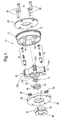
FIG. 1 is an exploded isometric view of a vane-type camshaft phaser in accordance with the invention; -
FIG. 2 is an exploded isometric view of a cover plate subassembly in accordance with the invention; -
FIG. 3 is an exploded view derived fromFIG. 2 showing the spring retainer fitted into the cover plate with the first slot and the cover plate notch aligned; -
FIG. 4 is an isometric view of the cover plate subassembly; -
FIG. 5 is an isometric view of an assembled camshaft phaser including a cross-sectional view taken off-axis through a pocket in the rotor, showing the rotor fully retarded from locked position; -
FIG. 6 is an isometric view of an assembled camshaft phaser including a cross-sectional view taken off-axis through a pocket in the rotor, showing the rotor in locked position; -
FIG. 7 is an isometric view of an assembled camshaft phaser including an axial cross-sectional view, also showing the rotor in locked position; and -
FIG. 8 is an isometric view of an assembled camshaft phaser including a cross-sectional view taken off-axis through a pocket in the rotor, showing the rotor in an advanced position. - Corresponding reference characters indicate corresponding parts throughout the several views. The exemplification set out herein illustrates one preferred embodiment of the invention, in one form, and such exemplification is not to be construed as limiting the scope of the invention in any manner.
- Referring to
FIGS. 1 through 8 , a vane-type camshaft phaser 10 in accordance with the invention comprises adriving element 12 in the form of a sprocket wheel integral with astator 14 having a plurality of inward-extendinglobes 16. Of course, drivingelement 12 may take the form, as is known in the art, of a notched wheel for receiving a toothed timing belt or a gear for meshing with a timing gear. Abottom plate 18 forms a first wall of chambers formed withinstator 14 betweenlobes 16. Arotor 20 having fourvanes 22a-d is disposed for rotation withinstator 14 in known fashion.Rotor 20 has at least one, and preferably two, lock pins assemblies 24 hydraulically extendable to engageseats 26 in acover plate 28 for rotationally locking the rotor to the stator as may be desired.Cover plate 28 defines a second wall of the chambers instator 14.Binder screws 30 extend throughbottom plate 18 andstator 14, and are threadedly received incover plate 28. Athrust washer 31 is disposed against the hub ofrotor 20 for receiving a camshaft-mounting bolt (not shown) during assembly ofengine 33. Aspring retainer 32 receives ahelical bias spring 34 having first and second radially-extendingtangs First tang 36 is grounded in a firstaxial slot 40 formed in the wall ofspring retainer 32 and is defined herein as the "inactive" tang.Second tang 38 is grounded in asecond slot 42 formed in the wall ofspring retainer 32 and is defined herein as the "active" tang.Second slot 42 preferably includes an axial entry portion and a circumferential portion permitting rotation ofsecond tang 38 during operation of the phaser.Spring retainer 32 extends through anopening 44 incover plate 28 and includes acollar 46 that grounds against theouter surface 48 ofcover plate 28 during assembly. Preferably anotch 50 is provided in the rim of opening 44 for receivingfirst tang 36 extending beyond the wall ofspring retainer 32. Alternatively,retainer 32 may be formed into the cover such as, for example, by casting. - During assembly of
phaser 10,bias spring 34 is captured and guided byspring retainer 32 that is press fit or formed intocover plate 28 withfirst slot 40 aligned withnotch 50. Referring toFIGS. 2 through 4 , in forming a cover plate subassembly 52,first tang 36 is inserted intoslot 40 to a depth untilsecond tang 38 engages the end ofspring retainer 32. Biasspring 34 is then wound untilsecond tang 38 aligns withsecond slot 42; the spring is then pushed further intospring retainer 32 and then released, thus the spring is captured at a pre-load position, creatingsubassembly 52. The spring retainer allows the bias spring to be installed into the cover in its pre-load position and to be conveniently retained therein as both the inactive and active tangs are captured in separate slot features in the spring retainer. -
Subassembly 52 is then attached bybinder screws 30 to the remaining phaser components to complete thefull phaser assembly 10. Anannular well 54 inrotor 20 receives the portion ofsubassembly 52 extending beyondcover plate 28. Apocket 56 within the rotor and outboard of well 54 receivesactive tang 38 and preferably has a tapered bottom face defining aramp 58.Ramp 58 extends angularly across thelower wall 60 ofsecond slot 42 and receivesactive tang 38 asspring 34 is torsionally actuated by rotation ofrotor 20. - In operation, when the rotor moves in a retarding direction (
FIG. 5 ), from an intermediate position in which the rotor may be locked,rotor ramp 58 liftsactive tang 38 off the lower slot wall 60 (hidden inFIG. 5 ) and positions tang 38 against afirst end wall 62 ofrotor pocket 56. Lifting the active tang of the bias spring removes any friction between the spring tang and the slot wall that would otherwise occur as the rotor moves in a retarded direction toward a full retarded authority position from its intermediate position. - As
rotor 20 moves in an advancing direction from a retard position and approaches the phase angle at which locking can occur (FIGS. 6 and7 ), the torsional rotation ofbias spring 34 stops whenactive tang 38 makes contact with end wall 64 (FIGS. 2 and 3 ) ofspring retainer slot 42. Contact between the active leg of the bias spring and the end of the slot in the spring retainer arrests the spring from further uncoiling and thus prevents spring torque from biasing the advance of the rotor in the advance direction past the locking point. This permits the rotor to self-align to its locking position when oil pressure is removed during engine shut down or stall. - Further motion of
rotor 20 past the locking position in an advancing direction toward a full advanced authority position (FIG. 8 ) causesramp 58 to be disengaged fromactive tang 38, removing any axial contact between the bias spring active tang and the non-rampbottom face 66 ofpocket 56, and therefore prevents frictional drag that otherwise would occur between the bias spring active tang and the rotor during rotor advance. - Without
slot wall 64 capturingactive tang 38, the spring would tip from axial alignment within the phaser and would continue to make contact withbottom face 66 as the rotor advances from the intermediate position. - The present invention has been described above in terms of a novel camshaft phaser being applied to an intake valve camshaft and biasing the rotor in the advance direction from retard positions. However, those of ordinary skill in the phaser art will realize that the disclosed invention is not so limited and may be applied to exhaust valve camshafts as well as to biasing the rotor in the retard direction from advanced positions as may be desired.
- While the invention has been described by reference to various specific embodiments, it should be understood that numerous changes may be made within the spirit and scope of the inventive concepts described. Accordingly, it is intended that the invention not be limited to the described embodiments, but will have full scope defined by the language of the following claims.
Claims (7)
- A camshaft phaser for varying the phase of a combustion valve in an internal combustion engine, comprising:a) a stator;b) a rotor disposed within said stator and having an annular well and a pocket formed in an axial side thereof and having a range of rotational authority within said stator including a first full authority position, a second full authority position opposite the first full authority position, and an intermediate position between said first and second full authority positions;c) a cover plate for enclosing said rotor within said stator and having a central opening;d) a spring retainer disposed within said central opening and extending into said annular well; ande) a bias spring having first and second tangs and being disposed within said spring retainer and also extending into said annular well,wherein said spring retainer includes first and second axially-extending slots formed in a wall thereof for receiving said first and second tangs, respectively, said second slot also having a circumferential portion having an end wall, and
wherein said first tang is grounded in said first slot and said second tang is rotatable within said circumferential portion, and
wherein said second tang protrudes into said rotor pocket, and
wherein said second tang engages an axial wall of said pocket to bias said rotor toward said intermediate position when said rotor is in a position between said intermediate position and one of said first or second full authority positions, and
wherein said second tang engages said end wall of said circumferential portion to prevent bias of said rotor when said rotor is in a position between said intermediate position and the other of said first or second full authority positions. - A camshaft phaser in accordance with Claim 1 wherein said notch in said central opening and said first slot are radially aligned and wherein said first tang protrudes radially from said first slot to engage said notch.
- A camshaft phaser in accordance with Claim 1 wherein said bias spring is torsionally pre-loaded in said spring retainer.
- A camshaft phaser in accordance with Claim 1 further comprising a driving element integral with said stator, and bottom plate, and binder screws for joining said bottom plate, stator and cover plate.
- A camshaft phaser in accordance with Claim 1 wherein said rotor pocket includes a bottom wall, wherein a first portion of said bottom wall defines a ramp for engaging and displacing said second tang axially during at least a portion of said rotational authority of said rotor.
- A camshaft phaser in accordance with Claim 5 wherein said bottom wall includes a second and non-ramp portion that is free of contact with said second tang during at least another portion of said rotational authority of said rotor.
- An internal combustion engine comprising a camshaft phaser disposed on a camshaft thereof, wherein said camshaft phaser includes
a stator,
a rotor disposed within said stator and having an annular well and a pocket formed in an axial side thereof and having a range of rotational authority within said stator including a first full authority position, a second full authority position opposite the first full authority position, and an intermediate position between said first and second full authority positions,
a cover plate for enclosing said rotor within said stator and having a central opening,
a spring retainer disposed within said central opening and extending into said annular well, and
a bias spring having first and second tangs and being disposed within said spring retainer and also extending into said annular well,
wherein said spring retainer includes first and second axially-extending slots formed in a wall thereof for receiving said first and second tangs, respectively, said second slot also having a circumferential portion having an end wall, and
wherein said first tang is grounded in said first slot and said second tang is rotatable within said circumferential portion, and
wherein said second tang protrudes into said rotor pocket, and
wherein said second tang engages an axial wall of said pocket to bias said rotor toward said intermediate position when said rotor is in a position between said intermediate position and one of said first or second full authority positions, and
wherein said second tang engages said end wall of said circumferential portion to prevent bias of said rotor when said rotor is in a position between said intermediate position and the other of said first or second full authority positions.
Applications Claiming Priority (1)
| Application Number | Priority Date | Filing Date | Title |
|---|---|---|---|
| US11/899,458 US7721692B2 (en) | 2007-09-06 | 2007-09-06 | Cam phaser having pre-loaded spring for biasing the rotor through only a portion of its range of authority |
Publications (2)
| Publication Number | Publication Date |
|---|---|
| EP2034139A2 true EP2034139A2 (en) | 2009-03-11 |
| EP2034139A3 EP2034139A3 (en) | 2010-04-14 |
Family
ID=40091336
Family Applications (1)
| Application Number | Title | Priority Date | Filing Date |
|---|---|---|---|
| EP08163298A Withdrawn EP2034139A3 (en) | 2007-09-06 | 2008-08-29 | Camshaft phaser having pre-loaded spring for biasing the rotor through only a part of its total shifting range. |
Country Status (3)
| Country | Link |
|---|---|
| US (1) | US7721692B2 (en) |
| EP (1) | EP2034139A3 (en) |
| JP (1) | JP2009062978A (en) |
Cited By (6)
| Publication number | Priority date | Publication date | Assignee | Title |
|---|---|---|---|---|
| EP2273077A1 (en) * | 2009-06-25 | 2011-01-12 | Schaeffler Technologies AG & Co. KG | Device for changing the phase of a camshaft relative to a crankshaft of a combustion engine |
| CN103590869A (en) * | 2012-08-14 | 2014-02-19 | 日立汽车系统株式会社 | Valve timing control apparatus of internal combustion engine |
| EP3109422A3 (en) * | 2015-06-26 | 2017-01-11 | Hyundai Motor Company | Rotation control apparatus of cvvt |
| DE102016207177B3 (en) * | 2016-04-27 | 2017-10-19 | Schaeffler Technologies AG & Co. KG | Camshaft adjuster with an axially wound torsion spring and a deformed, spring-guiding and pressure-tight sheet metal spring cover |
| CN110114558A (en) * | 2016-12-28 | 2019-08-09 | 株式会社三国 | Valve timing change device |
| CN114076007A (en) * | 2020-08-11 | 2022-02-22 | 舍弗勒技术股份两合公司 | Camshaft phaser and internal combustion engine |
Families Citing this family (14)
| Publication number | Priority date | Publication date | Assignee | Title |
|---|---|---|---|---|
| US20120298058A1 (en) * | 2011-05-27 | 2012-11-29 | Delphi Technologies, Inc. | System for attaching a camshaft phaser to a camshaft |
| JP2014055586A (en) * | 2012-08-14 | 2014-03-27 | Hitachi Automotive Systems Ltd | Valve timing control device of internal combustion engine |
| JP6091115B2 (en) * | 2012-09-07 | 2017-03-08 | 日立オートモティブシステムズ株式会社 | Valve timing control device for internal combustion engine and method for manufacturing the same |
| US9133735B2 (en) | 2013-03-15 | 2015-09-15 | Kohler Co. | Variable valve timing apparatus and internal combustion engine incorporating the same |
| JP5895927B2 (en) * | 2013-12-17 | 2016-03-30 | 株式会社デンソー | Valve timing adjustment device |
| US9341089B2 (en) | 2014-04-04 | 2016-05-17 | RB Distribution, Inc. | Camshaft phaser |
| DE102014207401B4 (en) * | 2014-04-17 | 2021-01-07 | Schaeffler Technologies AG & Co. KG | Camshaft adjuster |
| JP6222043B2 (en) * | 2014-10-31 | 2017-11-01 | アイシン精機株式会社 | Valve timing control device |
| US10072537B2 (en) | 2015-07-23 | 2018-09-11 | Husco Automotive Holdings Llc | Mechanical cam phasing system and methods |
| CN108331632B (en) | 2017-01-20 | 2021-12-28 | 胡斯可汽车控股有限公司 | Cam phasing systems and methods |
| JP2018168776A (en) * | 2017-03-30 | 2018-11-01 | アイシン精機株式会社 | Valve timing control device |
| US20190186369A1 (en) | 2017-12-20 | 2019-06-20 | Plasma Igniter, LLC | Jet Engine with Plasma-assisted Combustion |
| US10900387B2 (en) | 2018-12-07 | 2021-01-26 | Husco Automotive Holdings Llc | Mechanical cam phasing systems and methods |
| US12098661B2 (en) | 2022-11-02 | 2024-09-24 | Husco Automotive Holdings Llc | Cam phase actuator control systems and methods |
Family Cites Families (15)
| Publication number | Priority date | Publication date | Assignee | Title |
|---|---|---|---|---|
| DE3930157A1 (en) * | 1989-09-09 | 1991-03-21 | Bosch Gmbh Robert | DEVICE FOR ADJUSTING THE TURNING ANGLE ASSIGNMENT OF A CAMSHAFT TO YOUR DRIVE ELEMENT |
| US5172662A (en) * | 1992-02-24 | 1992-12-22 | Eaton Corporation | Camshaft phase change device |
| DE19916675B4 (en) * | 1999-04-14 | 2005-07-07 | Daimlerchrysler Ag | Device for relative angular adjustment of a camshaft |
| US6505586B1 (en) * | 1999-08-05 | 2003-01-14 | Denso Corporation | Variable valve timing control apparatus and method for engines |
| JP4158185B2 (en) * | 1999-12-15 | 2008-10-01 | 株式会社デンソー | Valve timing adjustment device |
| US6276321B1 (en) * | 2000-01-11 | 2001-08-21 | Delphi Technologies, Inc. | Cam phaser having a torsional bias spring to offset retarding force of camshaft friction |
| JP3964207B2 (en) * | 2000-01-25 | 2007-08-22 | 三菱電機株式会社 | Valve timing adjustment device |
| US6439184B1 (en) * | 2001-01-31 | 2002-08-27 | Denso Corporation | Valve timing adjusting system of internal combustion engine |
| US6732690B2 (en) * | 2002-05-21 | 2004-05-11 | Delphi Technologies, Inc. | Camshaft phaser having an external bias spring |
| JP2005155373A (en) * | 2003-11-21 | 2005-06-16 | Mitsubishi Electric Corp | Valve timing adjustment device |
| US6948467B2 (en) * | 2004-02-27 | 2005-09-27 | Delphi Technologies, Inc. | Locking pin mechanism for a vane-type cam phaser |
| JP4288220B2 (en) * | 2004-09-17 | 2009-07-01 | 株式会社日立製作所 | Valve timing control device for internal combustion engine |
| US7421989B2 (en) * | 2005-09-13 | 2008-09-09 | Delphi Technologies, Inc. | Vane-type cam phaser having increased rotational authority, intermediate position locking, and dedicated oil supply |
| US7363897B2 (en) * | 2006-06-06 | 2008-04-29 | Delphi Technologies, Inc. | Vane-type cam phaser having bias spring system to assist intermediate position pin locking |
| US7614370B2 (en) * | 2006-06-06 | 2009-11-10 | Delphi Technologies, Inc. | Vane-type cam phaser having bias spring system to assist intermediate position pin locking |
-
2007
- 2007-09-06 US US11/899,458 patent/US7721692B2/en active Active
-
2008
- 2008-08-18 JP JP2008210079A patent/JP2009062978A/en not_active Withdrawn
- 2008-08-29 EP EP08163298A patent/EP2034139A3/en not_active Withdrawn
Cited By (6)
| Publication number | Priority date | Publication date | Assignee | Title |
|---|---|---|---|---|
| EP2273077A1 (en) * | 2009-06-25 | 2011-01-12 | Schaeffler Technologies AG & Co. KG | Device for changing the phase of a camshaft relative to a crankshaft of a combustion engine |
| CN103590869A (en) * | 2012-08-14 | 2014-02-19 | 日立汽车系统株式会社 | Valve timing control apparatus of internal combustion engine |
| EP3109422A3 (en) * | 2015-06-26 | 2017-01-11 | Hyundai Motor Company | Rotation control apparatus of cvvt |
| DE102016207177B3 (en) * | 2016-04-27 | 2017-10-19 | Schaeffler Technologies AG & Co. KG | Camshaft adjuster with an axially wound torsion spring and a deformed, spring-guiding and pressure-tight sheet metal spring cover |
| CN110114558A (en) * | 2016-12-28 | 2019-08-09 | 株式会社三国 | Valve timing change device |
| CN114076007A (en) * | 2020-08-11 | 2022-02-22 | 舍弗勒技术股份两合公司 | Camshaft phaser and internal combustion engine |
Also Published As
| Publication number | Publication date |
|---|---|
| EP2034139A3 (en) | 2010-04-14 |
| JP2009062978A (en) | 2009-03-26 |
| US7721692B2 (en) | 2010-05-25 |
| US20090069097A1 (en) | 2009-03-12 |
Similar Documents
| Publication | Publication Date | Title |
|---|---|---|
| US7721692B2 (en) | Cam phaser having pre-loaded spring for biasing the rotor through only a portion of its range of authority | |
| EP1895113A2 (en) | Vane-type cam phaser having bias spring system to assist intermediate position pin locking | |
| US6948467B2 (en) | Locking pin mechanism for a vane-type cam phaser | |
| US8371257B2 (en) | Engine with dual cam phaser for concentric camshaft | |
| JP5739168B2 (en) | Valve timing control device for internal combustion engine | |
| US7421989B2 (en) | Vane-type cam phaser having increased rotational authority, intermediate position locking, and dedicated oil supply | |
| US8127728B2 (en) | Vane-type cam phaser having dual rotor bias springs | |
| US8387578B2 (en) | Camshaft phaser with dual lock pins and a passage within the camshaft phaser connecting the lock pins | |
| US7614370B2 (en) | Vane-type cam phaser having bias spring system to assist intermediate position pin locking | |
| KR20140057169A (en) | Camshaft phaser with centrally located lock pin valve spool | |
| EP2921662B1 (en) | Camshaft phaser | |
| US20120298058A1 (en) | System for attaching a camshaft phaser to a camshaft | |
| US8677962B2 (en) | Cam phaser locking systems | |
| EP2865855B1 (en) | Camshaft phaser and lock pin thereof | |
| US9470119B2 (en) | Camshaft phaser | |
| US6742485B2 (en) | Cam phaser locking pin assembly guide | |
| US6308669B1 (en) | Phase change coupling | |
| US6883479B2 (en) | VCT phaser having an electromagnetic lock system for shift and lock operation | |
| US6966288B2 (en) | Lock pin with centrifugally operated release valve | |
| CN110195624B (en) | Cam phaser between cam bearings | |
| CN111140305B (en) | Cam phaser camshaft coupling | |
| US6701878B2 (en) | Variable valve timing device | |
| US8881702B1 (en) | Camshaft phaser | |
| US10711658B1 (en) | Trigger wheel and drive plate for a concentric camshaft | |
| EP1447528A2 (en) | Vane-Type Camshaft Phaser |
Legal Events
| Date | Code | Title | Description |
|---|---|---|---|
| PUAI | Public reference made under article 153(3) epc to a published international application that has entered the european phase |
Free format text: ORIGINAL CODE: 0009012 |
|
| AK | Designated contracting states |
Kind code of ref document: A2 Designated state(s): AT BE BG CH CY CZ DE DK EE ES FI FR GB GR HR HU IE IS IT LI LT LU LV MC MT NL NO PL PT RO SE SI SK TR |
|
| AX | Request for extension of the european patent |
Extension state: AL BA MK RS |
|
| PUAL | Search report despatched |
Free format text: ORIGINAL CODE: 0009013 |
|
| AK | Designated contracting states |
Kind code of ref document: A3 Designated state(s): AT BE BG CH CY CZ DE DK EE ES FI FR GB GR HR HU IE IS IT LI LT LU LV MC MT NL NO PL PT RO SE SI SK TR |
|
| AX | Request for extension of the european patent |
Extension state: AL BA MK RS |
|
| AKY | No designation fees paid | ||
| REG | Reference to a national code |
Ref country code: DE Ref legal event code: 8566 |
|
| STAA | Information on the status of an ep patent application or granted ep patent |
Free format text: STATUS: THE APPLICATION IS DEEMED TO BE WITHDRAWN |
|
| 18D | Application deemed to be withdrawn |
Effective date: 20101015 |