EP2033349B1 - Wdm transport of sub-carrier-multiplexed signals over an optical fiber in low-dispersion spectral regions - Google Patents
Wdm transport of sub-carrier-multiplexed signals over an optical fiber in low-dispersion spectral regions Download PDFInfo
- Publication number
- EP2033349B1 EP2033349B1 EP07845253A EP07845253A EP2033349B1 EP 2033349 B1 EP2033349 B1 EP 2033349B1 EP 07845253 A EP07845253 A EP 07845253A EP 07845253 A EP07845253 A EP 07845253A EP 2033349 B1 EP2033349 B1 EP 2033349B1
- Authority
- EP
- European Patent Office
- Prior art keywords
- optical
- dispersion
- wavelengths
- zero
- fiber
- Prior art date
- Legal status (The legal status is an assumption and is not a legal conclusion. Google has not performed a legal analysis and makes no representation as to the accuracy of the status listed.)
- Not-in-force
Links
Images





Classifications
-
- H—ELECTRICITY
- H04—ELECTRIC COMMUNICATION TECHNIQUE
- H04B—TRANSMISSION
- H04B10/00—Transmission systems employing electromagnetic waves other than radio-waves, e.g. infrared, visible or ultraviolet light, or employing corpuscular radiation, e.g. quantum communication
- H04B10/27—Arrangements for networking
- H04B10/272—Star-type networks or tree-type networks
- H04B10/2725—Star-type networks without a headend
-
- H—ELECTRICITY
- H04—ELECTRIC COMMUNICATION TECHNIQUE
- H04B—TRANSMISSION
- H04B10/00—Transmission systems employing electromagnetic waves other than radio-waves, e.g. infrared, visible or ultraviolet light, or employing corpuscular radiation, e.g. quantum communication
- H04B10/27—Arrangements for networking
-
- H—ELECTRICITY
- H04—ELECTRIC COMMUNICATION TECHNIQUE
- H04J—MULTIPLEX COMMUNICATION
- H04J14/00—Optical multiplex systems
- H04J14/02—Wavelength-division multiplex systems
- H04J14/0201—Add-and-drop multiplexing
- H04J14/0202—Arrangements therefor
- H04J14/0206—Express channels arrangements
-
- H—ELECTRICITY
- H04—ELECTRIC COMMUNICATION TECHNIQUE
- H04J—MULTIPLEX COMMUNICATION
- H04J14/00—Optical multiplex systems
- H04J14/02—Wavelength-division multiplex systems
- H04J14/0201—Add-and-drop multiplexing
- H04J14/0202—Arrangements therefor
- H04J14/0209—Multi-stage arrangements, e.g. by cascading multiplexers or demultiplexers
-
- H—ELECTRICITY
- H04—ELECTRIC COMMUNICATION TECHNIQUE
- H04J—MULTIPLEX COMMUNICATION
- H04J14/00—Optical multiplex systems
- H04J14/02—Wavelength-division multiplex systems
- H04J14/0224—Irregular wavelength spacing, e.g. to accommodate interference to all wavelengths
-
- H—ELECTRICITY
- H04—ELECTRIC COMMUNICATION TECHNIQUE
- H04J—MULTIPLEX COMMUNICATION
- H04J14/00—Optical multiplex systems
- H04J14/02—Wavelength-division multiplex systems
- H04J14/03—WDM arrangements
- H04J14/0305—WDM arrangements in end terminals
-
- H—ELECTRICITY
- H04—ELECTRIC COMMUNICATION TECHNIQUE
- H04J—MULTIPLEX COMMUNICATION
- H04J14/00—Optical multiplex systems
- H04J14/02—Wavelength-division multiplex systems
- H04J14/0201—Add-and-drop multiplexing
- H04J14/0202—Arrangements therefor
- H04J14/0213—Groups of channels or wave bands arrangements
-
- H—ELECTRICITY
- H04—ELECTRIC COMMUNICATION TECHNIQUE
- H04J—MULTIPLEX COMMUNICATION
- H04J14/00—Optical multiplex systems
- H04J14/02—Wavelength-division multiplex systems
- H04J14/0201—Add-and-drop multiplexing
- H04J14/0215—Architecture aspects
- H04J14/0216—Bidirectional architectures
-
- H—ELECTRICITY
- H04—ELECTRIC COMMUNICATION TECHNIQUE
- H04J—MULTIPLEX COMMUNICATION
- H04J14/00—Optical multiplex systems
- H04J14/02—Wavelength-division multiplex systems
- H04J14/0201—Add-and-drop multiplexing
- H04J14/0215—Architecture aspects
- H04J14/0219—Modular or upgradable architectures
Definitions
- Embodiments of the invention relate generally to the field of transport of CATV and digital signals over optical fiber. More particularly, an embodiment of the invention relates to DWDM transport of CATV and digital signals over optical fiber in low-dispersion spectral regions.
- MSOs CATV Multiple System Operators
- ILECs Incumbent Local Exchange Carriers
- HSD High Speed Data subscribers
- MSOs were first to offer HSD services and, consequently, enjoyed the lion's share of this market until recently.
- ILECs have recently found success in increasing their share of the HSD market by offering prices below those charged by MSOs.
- MSOs have responded, not by lowering their prices, but by offering higher bandwidths for the same price.
- MSOs have historically been able to offer higher bandwidths on their hybrid fiber-coax (HFC) networks than ILECs with their traditional digital subscriber loop (DSL) services. Competing on the basis of bandwidth, rather than price, MSOs initially increased downstream speeds to 3 Mb/s, then 5 Mb/s and, more recently, to 10 Mb/s or higher for the same price they previously charged for only 1.5 Mb/s service.
- HFC hybrid fiber-coax
- DSL digital subscriber loop
- the fiber node (FN) is the demarcation point between the fiber network and the coax network in an HFC network.
- optical fiber provides enormous bandwidth.
- fiber nodes In HFC networks, fiber nodes have a nominal fiber service area of anywhere from 500 homes-passed to as many as 2,000 homes-passed. MSOs have been able to increase the bandwidth offered per subscriber by replacing older nodes with newer, segmentable nodes with multiple optical downstream receivers and upstream lasers, effectively reducing the fiber service area.
- the next step to increase bandwidth is to either locate a second node next to the original node or to augment the existing node with one or more nodes closer to the subscribers.
- both of these methods exacerbate the problem of fiber scarcity as they require additional fibers to support the new nodes.
- Even MSOs with the foresight to place several fibers to each node are now finding that the available fibers are not sufficient for the number of new nodes that are required.
- node cluster nodes that serve 100 homes-passed but several nodes (often called a node cluster) share forward and reverse fiber to serve the same amount of homes-passed (500 to 2000). In the future, these same fibers will have to support cluster segmentation into individual nodes.
- DWDM dense wavelength-division-multiplexing
- L-Band DWDM L-Band DWDM
- Standard transmission fiber such as Coming SMF-28 or its equivalent, with a zero dispersion wavelength in the O-Band (1260 nm to 1360 nm)
- Longer or more technically challenging links may employ not only standard transmission fiber, but other types of fiber such as dispersion-shifted fiber, large effective area fiber, or mixtures of fiber types in order to manage dispersion or other impairments.
- C-Band DWDM technology has been successfully applied to HFC networks.
- Such architectures employ a broadcast layer that typically consists of an externally modulated broadcast transmitter carrying sub-carrier-multiplexed (SCM) analog video and QAM-modulated RF signals together with a narrowcast overlay consisting of directly modulated lasers transporting QAM-modulated RF sub-carriers transporting video, voice, and data.
- SCM sub-carrier-multiplexed
- narrowcast overlay consisting of directly modulated lasers transporting QAM-modulated RF sub-carriers transporting video, voice, and data.
- WDM wavelength-division multiplexing
- CWDM coarse-wavelength-division-multiplexing
- the third-order nonlinear optical susceptibility of the optical fiber leads to crosstalk between optical carriers through the effects of Stimulated Roman Scattering (SRS), self-phase modulation (SPM), cross-phase modulation (XPM), and the more general case of four-wave-mixing (4WM).
- SRS Stimulated Roman Scattering
- SPM self-phase modulation
- XPM cross-phase modulation
- 4WM four-wave-mixing
- the light emitted by a directly-modulated DFB laser exhibits frequency chirp - the wavelength of the light emitted by the laser varies with the output power of the laser.
- Chromatic dispersion of the optical fiber acts upon this frequency-chirped light to create distortion in the sub-carrier multiplexed signals of typical analog CATV video transport, primarily composite second-order (CSO) distortion.
- SPM can be a problem in single-channel systems
- the main sources of crosstalk in WDM systems are XPM (cross-phase modulation) and SRS (simulated Raman scattering).
- SRS-induced crosstalk dominates over XPM crosstalk for channel separation greater than several nm, such as in CWDM systems.
- SRS crosstalk is a function of the RF frequency, optical power and fiber length.
- the severity of SRS crosstalk as a function of the wavelength separation of two sub-carrier-multiplexed lightwaves at the CATV frequencies of 55 MHz and 499 MHz are shown in Figures 1 and 2 for typical CATV power levels and fiber distances. This crosstalk severely limits the number of downstream CWDM wavelengths and their launch power into the fiber.
- the worst case CSO for analog channels in the broadcast band (55 MHz - 550 MHz) occurs at the upper edge of the band and is plotted in Figure 3 for various values of laser chirp. Note that since this is due to a linear fiber effect, the induced CSO is independent of optical power in the fiber. However, the dispersion-induced CSO depends on the total dispersion in the fiber (especially SMF-28 and equivalent fibers), which is usually greater if the wavelength (optical frequency) is further away from the zero dispersion wavelength of the fiber.
- U.S. Patent No. 5,430,568 discloses a method of transmitting RF signals mixing different wavelengths over an optical fibre.
- U.S. Patent No. 6,407,842 discloses a method and apparatus for transmitting an optical signal through an optical fiber.
- U.S. Patent No. 6,545,780 discloses using a combination of a plurality of completely unequally spaced channel allocations to mitigate the influence of four wave mixing.
- Shigeki Aisawa et al “Per formance of NRZ Versus RZ- WDM Transmission Around Zero Dispersion Wavelength Over Dispersion Shifted Fiber" IEEE Photonics Technology Letters vol 10 No. 4, April 1998 describes how in multi-repeater WDM transmission systems employing installed dispersion shifted fiber, non-return to zero signals offer superior performance to return to zero signals except in special cases.
- EP 1136638 A discloses an optical wavelength division multiplexing transmission system using two optical fiber transmission paths having different zero dispersion wavelengths.
- a method comprises transporting a plurality of optical carriers of different wavelengths over an optical link using wavelength division multiplexing, the optical link including a plurality of optical segments, wherein a plurality of optical channel center wavelengths defined by the plurality of optical carriers are clustered proximate an average value of zero-dispersion wavelength of the optical link, or near either a) a low wavelength edge or b) a high wavelength edge of a range of zero-dispersion wavelengths of the optical link, the range defined i) by absolute limits of manufacturers' specifications or ii) statistically by a characteristic width of a distribution function describing a set of zero-dispersion frequency values in the plurality of optical segments, and wherein a plurality of optical channel center frequencies defined by the plurality of optical channel center wavelengths are non-uniformly spaced apart, wherein the plurality of optical carriers of different wavelengths transport at least one signal selected from the group comprising radio frequency (RF) sub-carrier-multiplexed (SCM) analog
- RF radio frequency
- all differences between all of the plurality of optical channel center frequencies are unique to produce a non-uniformly spaced set of optical channel center frequencies whose four-wave mixing products are not equal to one of more of the plurality of the optical channel center frequencies.
- optical channel frequencies of the optical carriers are multiples of a minimal frequency separation.
- all of the plurality of optical channel center wavelengths are clustered within 50 nm of the zero-dispersion wavelength of the transport fiber.
- spacings between the plurality of optical channel wavelengths are from approximately 0.5 nm to approximately 20nm.
- an apparatus comprises a low dispersion wavelength division multiplexing network transporting a plurality of optical carriers of different wavelengths using a wavelength division multiplexing, the low dispersion wavelength division multiplexing network including: an optical multiplexer (403, 405) ; an optical link coupled to the multiplexer, the optical link including a plurality of optical segments; and an optical demultiplexer (403, 405) coupled to the optical link, wherein a plurality of optical channel center wavelengths defined by the plurality of optical carriers are clustered proximate an average value of a zero-dispersion wavelength of the optical link, or near either a) a low wavelength edge or b) a high wavelength edge of a range of zero-dispersion wavelengths of the optical link, the range defined i) by absolute limits of manufacturers' specifications or ii) statistically by a characteristic width of a distribution function describing a set of zero-dispersion frequency values in the plurality of optical segments, and wherein a plurality of optical channel
- the invention presented here solves the problem of cost-effectively expanding bandwidth capacity in fiber-scarce HFC networks by transporting multiple wavelengths over a single fiber using a DWDM system whose wavelengths are densely clustered close to the zero dispersion wavelength of the transport fiber.
- SMF-28 and equivalent fibers which are predominant in access HFC networks, such wavelengths lie in the O-Band (1260nm - 1360nm).
- the invention is generally applicable to the use of wavelength division multiplexing near the zero-dispersion wavelength of any fiber, including, but not limited to, dispersion shifted and other fibers whose zero-dispersion wavelength lies in different spectral regions.
- LDWDM low dispersion wavelength division multiplexing
- a WDM system operating in a low-dispersion spectral region is distinctly different from other WDM technologies, such as CWDM and C-Band and L-Band DWDM that operate far from the zero dispersion wavelength of the fiber. It can be seen from Figures 1 , 2 and 3 that by clustering several wavelengths near the zero-dispersion wavelength of the transport fiber (for SMF-28 or equivalent fiber, this is approximately 1311 nm), the problems of SRS-induced crosstalk and dispersion/chirp-induced CSO that plague other WDM technologies are greatly ameliorated.
- an LDWDM system operates close to the zero dispersion wavelength of the fiber, a wide variety of signals, including RF SCM analog video, RF SCM quasi-analog signals such as M-QAM and N-VSB, and digital signals such as SONET, GbE, 10GbE, FC-1, FC-2, FC-10, etc., can be transported on multiple DWDM wavelengths over a single fiber without the need for significant restrictions on laser transmitter chirp. Consequently, either externally-modulated or directly-modulated laser transmitters can be used in an LDWDM system.
- the major advantage provided by this invention is the ability to use low-cost, directly modulated lasers with constraints on laser chirp that do not differ significantly from those placed on 1310 nm directly-modulated DFB lasers that are used in current generation transmitters.
- C-Band and L-Band DWDM In contrast to LDWDM, competing WDM technologies such as CWDM or C-Band and L-Band DWDM that transport analog or quasi-analog signals using directly-modulated DFB laser transmitters operating at wavelengths far from the zero-dispersion wavelength of the fiber must restrict the type or the bandwidth of signals they transport, the number of usable wavelengths, or the transport distance in the fiber.
- C-Band and L-Band DWDM directly-modulated laser transmitters can carry only QAM and digital signals with strict frequency allocation rules.
- LDWDM is a wavelength division multiplexed communication system designed and optimized to operate with multiple wavelengths in close proximity to the zero dispersion wavelength of the transport fiber.
- the system includes separate, unidirectional upstream and downstream links.
- the downstream link is comprised ofN (where N ⁇ 2) laser transmitters 100, each at a distinct wavelength selected from an optical channel plan (to be described in detail below), whose outputs are combined by an optical multiplexer 101 onto a transport fiber 102 and then separated into individual wavelengths by an optical demultiplexer 103.
- Each wavelength is delivered by optical fiber 104 to a receiver 105.
- Each receiver 105 may be located near the optical demultiplexer 103, or may be located some distance away, such as in remote nodes or terminals.
- Downstream laser transmitters 100 may be located with the optical multiplexer 101 in a headend, hub, central office, or other similar signal processing facility, or the downstream laser transmitters 100 and optical multiplexer 101 may be functionally distributed among several headends, hubs, central offices, or similar signal processing facilities.
- the downstream optical demultiplexer 103 may be located in a hub or a remote facility such as a node, fiber splice enclosure, fiber management cabinet, or similar facility, or the optical demultiplexer 103 may be functionally distributed among several such facilities.
- the optical receivers 105 may be located near the optical demultiplexer 103 or may be located at various distances from it in remote nodes or terminals.
- An upstream link includes M (where M may or may not equal N) return laser transmitters 106, each at a distinct wavelength selected from an optical channel plan, whose outputs are delivered to the inputs of an optical multiplexer 108 by optical fibers 107.
- the return laser transmitters 106 may be located near the optical multiplexer 108 or may be located various distances away, such as in remote nodes or terminals.
- the optical multiplexer 108 combines the outputs of the return laser transmitters 106 onto a transport fiber 109. The combined wavelengths are separated into individual wavelengths by an optical demultiplexer 110. Each wavelength is delivered by optical fiber to a return receiver 111.
- the return laser transmitters 106 may be located in nodes or terminals that may be located near the upstream optical multiplexer 108 or remotely from it.
- the upstream optical multiplexer 108 may be located in a hub or a remote facility such as a node, fiber splice enclosure, fiber management cabinet, or similar facility, or the optical multiplexer 108 may be functionally distributed among several such facilities.
- the return receivers 111 may be located with the optical demultiplexer 110 in a headend, hub, central office, or other similar signal processing facility, or the return receivers 111 and optical demultiplexer 110 may be functionally distributed among several headends, hubs, central offices, or similar signal processing facilities.
- the preferred embodiment would use directly-modulated DFB laser transmitters because of their cost advantage; however, externally-modulated transmitters may also be used in either link.
- the transmitters 100 and 106 may transport a variety of signals, such as but not limited to RF SCM analog-modulated video, RF SCM M-QAM and N-VSB, and digital signals such as SONET, GbE, 10GbE, Fiber Channel, etc.
- the individual wavelength at which each downstream laser transmitter 100 operates is selected from a set of optical channel wavelengths that are in close proximity to the zero dispersion wavelength of the downstream transport fibers 102 and 104.
- the individual wavelength of each return laser transmitter 106 is selected from a set of optical channel wavelengths that are in close proximity to the zero dispersion wavelength of the upstream transport fibers 107 and 109.
- the wavelengths of transmitters 100 would lie in the O-Band.
- the wavelengths of the transmitters 100 would lie in the C-Band.
- the wavelengths of transmitters 106 would lie in the O-Band.
- the wavelengths of the transmitters 106 would lie in the C-Band.
- the optical channel center wavelengths, optical channel passbands and optical channel spacings of the optical multiplexers 101 and 108 and the optical demultiplexers 103 and 110 are determined by the optical channel frequency plan.
- the optical channel separation or spacing of the optical frequency plan is non-uniform, as will be discussed below.
- a typical embodiment would have multiple wavelengths whose channel spacing ranges from 0.5 nm up to 20 nm, although other channel spacing ranges are possible.
- the optical multiplexers 101 and 108 and the optical demultiplexers 103 and 110 may be implemented by a variety of technologies including, but not limited to, thin film interference filters, fiber Bragg gratings, bulk diffraction gratings, array waveguide gratings, and may be implemented in a consolidated or a distributed manner.
- FIG. 5 A block diagram of a bidirectional LDWDM system, where downstream and upstream communication signals are transported on a common transport fiber, is presented in Figure 5 .
- mux/demux bidirectional optical multiplexer/demultiplexer
- J optical carriers are separated into individual wavelengths or frequencies by a bidirectional optical mux/demux 153.
- Each of the J downstream optical carriers separated at the bidirectional mux/demux is carried by separate optical fibers 155, 157 to corresponding downstream receivers 156, 158, which may be located in remote nodes or terminals.
- the remaining N-J optical carriers are directed to the pass-through port 154 of the bidirectional mux/demux 153 and carried by bidirectional transport fibers 159, 163, and 167 through a cascade of optical add/drop multiplexers 160, 164, 168, each of which selects a particular downstream wavelength to deliver to corresponding downstream receivers 162, 166, 169, which may be located in remote nodes or terminals.
- N-J return laser transmitters 187, 186, 185 each at a distinct wavelength or frequency selected from an optical channel plan (described in detail below) are multiplexed by a cascade of optical add/drop multiplexers 168, 164, 160 onto bidirectional transport fibers 167, 163, 159 and into the pass-through port 154 of the bidirectional optical mux/demux 153.
- the outputs of the J return laser transmitters 180, 182, each at a distinct optical frequency or wavelength selected from an optical channel plan (described in detail below), are multiplexed with the outputs of return laser transmitters 185, 186, 187 by the bidirectional optical mux/demux 153 onto the bidirectional transport fiber 152.
- the bidirectional optical mux/demux 151 separates the N return optical carriers by individual wavelengths and delivers them to corresponding return receivers 190.
- the downstream laser transmitters 150, the bidirectional mux/demux 151, and the return receivers 190 may typically be located in a headend, hub, central office, or similar signal processing facility.
- the downstream receivers 156, 158, 162, 166, 169 and the return transmitters 180,182, 185, 186, 187 may typically be located in optical nodes or remote terminals.
- the preferred embodiment would use directly-modulated DFB laser transmitters because of their cost advantage; however, externally-modulated transmitters may also be used in any link.
- the transmitters 100 and 106 may transport a variety of signals, such as but not limited to RF SCM analog-modulated video, RF SCM M-QAM and N-VSB, and digital signals such as SONET, GbE, 10GbE, Fiber Channel, etc.
- the individual wavelengths at which each downstream laser transmitter 150 and each return laser transmitter 180, 182, 185, 186, 187 operates is selected from a set of optical channel wavelengths that are in close proximity to the zero dispersion wavelength of the bidirectional transport fibers 152, 159, 163, 167.
- the wavelengths of transmitters 150, 180, 182, 185, 186, 187 would lie in the O-Band.
- the wavelengths of transmitters 150, 180, 182, 185, 186, 187 would lie in the C-Band.
- optical channel center wavelengths, optical channel passbands and optical channel spacings of the bidirectional optical mux/demuxes 151, 153 and the optical add/drop multiplexers 160, 164, 168 are determined by the optical channel frequency plan.
- the optical channel separation or spacing of the optical frequency plan is non-uniform, as will be discussed below.
- a typical embodiment would have multiple wavelengths whose channel spacing ranges from 0.5 nm up to 20 nm, although other channel spacing ranges are possible.
- the bidirectional optical mux/demuxes 151, 153 and the optical add/drop multiplexers 160, 164, 168 may be implemented by a variety of technologies including, but not limited to, thin film interference filters, fiber Bragg gratings, bulk diffraction gratings, array waveguide gratings, and may be implemented in a consolidated or a distributed manner.
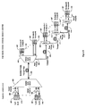
- the block diagram of a unidirectional LDWDM system with distributed optical multiplexing and demultiplexing is presented in Figure 6 .
- the system includes separate, unidirectional upstream and downstream links.
- the downstream link is comprised ofN (where N ⁇ 2) laser transmitters 200, each at a distinct wavelength selected from an optical channel plan, whose outputs are combined by an optical multiplexer (mux) 201 onto a transport fiber 202.
- An optical demultiplexer (demux) 203 separates J optical carriers into individual wavelengths and delivers them by optical fibers 206, 208 to downstream receivers 205, 207, which may be located in remote nodes or terminals.
- the remaining N-J optical carriers are directed to the pass-through port 204 and carried by transport fibers 209, 213, 217 through a cascade of optical add/drop multiplexers 210, 214, 218, each of which selects a particular wavelength to deliver to corresponding downstream receivers 211, 215, 219, which may be located in remote nodes or terminals.
- N-J return laser transmitters 245, 241, 237, each at a distinct optical frequency selected from an optical channel plan are multiplexed by a cascade of optical add/drop multiplexers 244, 240, 236 onto transport fibers 243, 239, 235 and into the pass-through port 234 of optical multiplexer 250.
- the outputs of J return laser transmitters 230, 232, each at a distinct optical frequency selected from an optical channel plan are multiplexed with the outputs of return laser transmitters 245, 241, 237 by optical multiplexer 250 onto the transport fiber 246.
- the optical demux 247 separates the N return optical carriers by individual wavelength and delivers them to return receivers 248.
- the downstream receivers 205, 207, 211, 215, 219 and the return laser transmitters 230, 232, 237, 241, 245 may be located in remote nodes or terminals.
- the downstream optical demux 203 and the upstream optical multiplexer 250 may be jointly or separately located in hubs or remote facilities such as nodes, fiber splice enclosures, fiber management cabinets, or similar facilities.
- the optical add/drop multiplexers 210, 214, 218, 236, 241, 245 may be located jointly or separately in remote nodes, terminals, fiber splice enclosures, fiber management cabinets, or similar facilities.
- the downstream transmitters 200 and the return receivers 248 may be located with the downstream optical multiplexer 201 and the upstream optical demultiplexer 247 in a headend, hub, central office, or other similar signal processing facility, or the downstream transmitters 200, the return receivers 248, the downstream optical multiplexer 201 and the upstream optical demultiplexer 247 may be functionally distributed among several headends, hubs, central offices, or similar signal processing facilities.
- the preferred embodiment would use directly-modulated DFB laser transmitters because of their cost advantage; however, externally-modulated transmitters may also be used in either link.
- the transmitters 200, 230, 232, 237, 241, 245 may transport a variety of signals, such as but not limited to RF SCM analog-modulated video, RF SCM M-QAM and N-VSB, and digital signals such as SONET, GbE, 10GbE, Fiber Channel, etc.
- the individual wavelength at which each downstream laser transmitter 200 operates is selected from a set of optical channel wavelengths that are in close proximity to the zero dispersion wavelength of the downstream transport fibers 202, 206, 208, 209,213, 217.
- the individual wavelength of each return laser transmitter 230, 232, 237, 241, 245 is selected from a set of optical channel wavelengths that are in close proximity to the zero dispersion wavelength of the upstream transport fibers 231, 233, 243, 239, 235, 246.
- the wavelengths of transmitters 200 would lie in the O-Band.
- the wavelengths of the transmitters 200 would lie in the C-Band.
- the transport fibers 231, 233, 243, 239, 235, 246 are SMF-28 or an equivalent fiber type, the wavelengths of transmitters 230, 232, 237, 241, 245 would lie in the O-Band.
- the wavelengths of the transmitters 230, 232, 237, 241, 245 would lie in the C-Band.
- optical channel center wavelengths, optical channel passbands and optical channel spacings of the optical multiplexers 201, 250, the optical demultiplexers 203 and 247, and the optical add/drop multiplexers 210, 214, 218, 236, 240, 244 are determined by the optical channel frequency plan.
- the optical channel separation or spacing of the optical frequency plan is non-uniform.
- a typical embodiment would have multiple wavelengths whose channel spacing ranges from 0.5 nm up to 20 nm, although other channel spacing ranges are possible.
- optical multiplexers 201, 250, the optical demultiplexers 203 and 247, and the optical add/drop multiplexers 210, 214, 218, 236, 240, 244 may be implemented by a variety of technologies including, but not limited to, thin film interference filters, fiber Bragg gratings, bulk diffraction gratings, array waveguide gratings, and may be implemented in a consolidated or a distributed manner.
- FIG. 7 presents a block diagram of a bidirectional "mixed" system of O-Band optical carriers and "legacy" CWDM or DWDM optical carriers.
- the outputs of N-J (where N-J ⁇ 1) CWDM/DWDM laser transmitters 301 are combined by a CWDM/DWDM bidirectional optical mux/demux 303, whose common port is connected to the pass-through port 305 of an appropriately designed bidirectional O-Band optical mux/demux 302.
- the O-Band bidirectional mux/demux 302 then combines the N-J CDWM or DWDM transmitter outputs with the outputs of J (where J ⁇ 2) O-Band laser transmitters 300, each at a distinct wavelength or frequency selected from an O-Band optical channel plan, onto a common bidirectional transport fiber 306. Downstream O-Band carriers are separated into individual wavelengths by an appropriately designed O-Band bidirectional optical mux/demux 307 and directed by optical fiber to downstream receivers 309, which may be located in remote nodes or terminals.
- the remaining group of downstream CWDM/DWDM optical carriers are directed through the pass-through port 308 of the bidirectional optical mux/demux 307 to a transport fiber 310 and into the common port of a CWDM /DWDM bidirectional optical mux/demux 311.
- the CWDM /DWDM bidirectional mux/demux 311 then separates the CWDM/DWDM optical carriers into individual wavelengths and directs them via optical fiber to downstream receivers 312, which may be located in remote nodes or terminals.
- the outputs ofN-J CWDM/DWDM return laser transmitters 320 which may be located in remote nodes or terminals, are combined by the CWDM/DWDM bidirectional optical mux/demux 311 onto a bidirectional transport fiber 310 and into the O-Band bidirectional mux/demux 307 via the pass-through port 308.
- the O-Band bidirectional mux/demux 307 combines the CWDM/DWDM optical carriers with the outputs of J O-Band return transmitters 321, each at a distinct frequency selected from an O-Band optical channel plan, onto a common bidirectional transport fiber 306.
- the O-Band bidirectional mux/demux 302 separates the J O-Band optical carriers into individual wavelengths and directs them to return receivers 322.
- the CWDM/DWDM optical carriers are directed through the pass through port 305 of the O-Band bidirectional mux/demux 320 to a bidirectional CWDM/DWDM mux/demux that separates the CWDM/DWDM upstream optical carriers into distinct wavelengths and directs them to return receivers 323.
- the downstream laser transmitters 300, 301 and the bidirectional mux/demuxes 302, 303 may be located in a headend, hub, central office, or similar signal processing facility.
- the bidirectional mux/demuxes 307, 311 may be located in a hub or a remote facility such as a fiber splice enclosure, fiber management cabinet, or similar facility.
- the preferred embodiment would use directly-modulated DFB O-Band laser transmitters 300, 321 because of their cost advantage; however, externally-modulated transmitters may also be used in either link.
- the O-Band transmitters 300,321 may transport a variety of signals, such as but not limited to RF SCM analog-modulated video, RF SCM M-QAM and N-VSB, and digital signals such as SONET, GbE, 10GbE, Fiber Channel, etc.
- the CWDM/DWDM transmitters 301,320 may be restricted in their signal content as described previously.
- One of the legacy channels could also be a 1550nm externally modulated laser transporting analog and QAM signals.
- the optical channel center wavelengths, optical channel passbands and optical channel spacings of the bidirectional optical mux/demuxes 302, 307 are determined by the optical channel frequency plan and the need to accommodate CWDM/DWDM wavelengths.
- the wavelength separation between the legacy CWDM/DWDM channels and the O-Band channels has to be controlled to prevent SRS-induced crosstalk between the O-Band channels and the CWDM/DWDM channels.
- the optical channel separation or spacing of the O-Band optical frequency plan is non-uniform.
- a typical embodiment would have multiple O-Band wavelengths whose channel spacing ranges from 0.5 nm up to 20 nm, although other channel spacing ranges are possible.
- the O-Band bidirectional optical mux/demuxes 302, 307 may be implemented by a variety of technologies including, but not limited to, thin film interference filters, fiber Bragg gratings, bulk diffraction gratings, array waveguide gratings, and may be implemented in a consolidated or a distributed manner.
- Appropriate optical amplification technology may also be used with LDWDM systems, as shown by the embodiment presented in Figure 8 , and optically amplified bidirectional LDWDM system.
- the outputs ofN downstream laser transmitters 401, each at a distinct wavelength or frequency selected from an optical frequency channel plan, are amplified by optical amplifiers 402 and combined onto a common bidirectional optical transport fiber 404 by a bidirectional optical multiplexer/demultiplexer (mux/demux) 403.
- J optical carriers are separated into individual wavelengths or frequencies by a bidirectional optical mux/demux 405.
- Each of the J downstream optical carriers separated at the bidirectional mux/demux is carried by optical fibers to corresponding downstream receivers 407, which may be located in remote nodes or terminals.
- the remaining N-J optical carriers are directed to the pass-through port 406 of the bidirectional mux/demux 405 and carried by bidirectional transport fibers 408, 411, 414 through a cascade of bidirectional optical add/drop multiplexers 409, 412, 415, each of which selects a particular downstream wavelength to deliver to corresponding downstream receivers 407, which may be located in remote nodes or terminals.
- N-J return laser transmitters 416 each at a distinct wavelength or frequency selected from an optical channel plan, and which may be optically amplified by an optical amplifier 417, are then multiplexed by a cascade of bidirectional optical add/drop multiplexers 409, 412 ,415 onto bidirectional transport fibers 408, 411, 414 and into the pass-through port 406 of the bidirectional optical mux/demux 405.
- the outputs of the J return laser transmitters 416 are multiplexed with the outputs of the N-J return laser transmitters 416 by the bidirectional optical mux/demux 405 onto the bidirectional transport fiber 404.
- the bidirectional optical mux/demux 403 separates the N return optical carriers by individual wavelengths and delivers them to corresponding return receivers 418.
- the downstream laser transmitters 401, the bidirectional mux/demux 403, and the return receivers 418 may typically be located in a headend, hub, central office, or similar signal processing facility.
- the downstream receivers 407 and the return transmitters 416 may typically be located in optical nodes or remote terminals.
- the preferred embodiment would use directly-modulated DFB laser transmitters because of their cost advantage; however, externally-modulated transmitters may also be used in any link.
- the transmitters 401 and 416 may transport a variety of signals, such as but not limited to RF SCM analog-modulated video, RF SCM M-QAM and N-VSB, and digital signals such as SONET, GbE, 10GbE, Fiber Channel, etc.
- the individual wavelengths at which each downstream laser transmitter 401 and each return laser transmitter 416 operates is selected from a set of optical channel wavelengths that are in close proximity to the zero dispersion wavelength of the transport fibers 404, 408, 411, 414.
- the wavelengths of transmitters 401, 416 would lie in the O-Band.
- Optical amplifiers 402, 417 would use O-Band optical amplification technology such as, but not limited to, praseodymium doped fiber amplifiers (PDFAs), semiconductor optical amplifiers, Raman amplifiers or other O-Band amplification technology.
- transport fibers 404, 408, 411, 414 are dispersion shifted fibers with zero-dispersion wavelength in the C-Band
- the wavelengths of transmitters 401, 416 would lie in the C-Band
- optical amplifiers 402, 417 would use optical amplification technology such as, but not limited to, erbium doped fiber amplifiers (EDFAs).
- optical channel center wavelengths, optical channel passbands and optical channel spacings of the bidirectional optical mux/demuxes 403, 405 and the optical add/drop multiplexers 409, 412, 415 are determined by the optical channel frequency plan.
- the optical channel separation or spacing of the optical frequency plan is non-uniform.
- a typical embodiment would have multiple wavelengths whose channel spacing ranges from 0.5 nm up to 20 nm, although other channel spacing ranges are possible.
- the bidirectional optical mux/demuxes 403, 405 and the optical add/drop multiplexers 409, 412, 415 may be implemented by a variety of technologies including, but not limited to, thin film interference filters, fiber Bragg gratings, bulk diffraction gratings, array waveguide gratings, and may be implemented in a consolidated or a distributed manner.
- Optical channel plans for low-dispersion-regime DWDM systems must be optimized against several competing constraints. While operation close to the zero-dispersion wavelength using narrow channel spacing alleviates the problems of SRS-induced crosstalk and dispersion/chirp-induced CSO, other types of crosstalk caused by fiber nonlinearities such as XPM and 4WM become dominant for small channel spacing in this spectral region of the optical fiber.
- XPM arises when the power in one modulated wavelength channel induces a small change in the refractive index of the fiber (through the nonlinear refractive index), which in turn induces a phase modulation (PM) on the other wavelengths.
- chromatic dispersion in the fiber then converts this phase modulation to intensity modulation (IM).
- IM intensity modulation
- the PM to IM conversion causes some amount of the modulated signal on one optical carrier to appear on other optical carriers, i.e. crosstalk. Since chromatic dispersion is necessary for XPM crosstalk, XPM crosstalk near the zero-dispersion wavelength is negligible.
- frequency mixing terms of concern are those that lie in proximity to the zero-dispersion wavelength of the fiber and are phase-matched for the mixing interaction - these frequency mixing products are all of the form f i +f j -f k , where k is distinct from i or j.
- HFC access networks have historically used SMF-28 or equivalent fibers.
- the zero-dispersion wavelength is located at approximately 1311 nm in O-Band but the invention applies to any DWDM system with directly modulated DFB transmitters with wavelengths located in proximity to the zero-dispersion wavelength of the fiber used.
- Equally spaced channels would therefore be employed only with large channel spacings and/or at wavelengths far from the zero-dispersion wavelength so that four-wave mixing products are sufficiently weak due to lack of phase-matching. It may also be possible to use equally spaced channels by restricting analog video to be the same for all wavelengths (for broadcast applications) and allow only the narrowcast QAM channels, which are more robust to crosstalk, to differ.
- mixing efficiency can also be reduced by increasing DWDM channel spacing.
- Mixing efficiency is also very sensitive to optical power levels, having a 20 log(P) dependence on DWDM channel power.
- 4WM is minimized by dispersion management whereby fiber spools with positive and negative dispersion are alternated to achieve a net dispersion of zero while maintaining a non-zero dispersion at all points of the fiber link.
- This technology cannot be used in short optical access links with sub-carrier-multiplexed (SCM) analog video and QAM-modulated RF signals transporting video, voice, and data due to limited loss budget over which these links operate and lack of cost-effective optical amplification technology for this application.
- SCM sub-carrier-multiplexed
- Analog video transmission can tolerate only extremely low levels of crosstalk.
- Reduction of crosstalk to acceptably low levels can be achieved by the following 4WM crosstalk suppression techniques: operation at wavelengths slightly offset from the fiber zero-dispersion wavelength and the use of unequal optical channel spacings. Although this is bandwidth inefficient, most WDM systems use channel spacing much larger than the bandwidth of the signals. Unequal channel spacing uses some of this "waisted bandwidth" to place 4WM products away from the channels. Note that it is not sufficient for the mixing products to be offset from the WDM channels; the offset of the mixing products from the WDM channels must be larger than the passband of the WDM filters used for multiplexing and demultiplexing. Mixing products can be guaranteed not to fall on WDM channels by requiring the difference between any two channel frequencies to be unique.
- the challenge presented by distortion and crosstalk due to linear and nonlinear optical fiber effects on RF SCM analog video and RF QAM carriers has prevented the development and deployment of a multi-wavelength system operating in proximity to the zero-dispersion wavelength of single mode optical fiber with full RF channel load from the lowest to the highest forward frequency of SCM systems (typically used in, but not limited to, cable TV applications with frequency range from 50 to 1002 MHz in North America, 65 to 1002 MHz in Japan and from 85 to 1002 MHz in Europe).
- the main characteristic of the fully loaded signal spectrum with SCM analog and QAM channels is that the RF load occupies several octaves of the RF spectrum.
- optical frequency channel plans for low-dispersion dense wavelength division multiplex systems (LDWDM) are possible, depending upon how competing constraints are balanced.
- optical frequency channel plans can be described generally by characteristic features and constraints.
- any set of segments of a given fiber type such as SMF-28 or an equivalent, will exhibit a range of zero-dispersion frequencies from f 0,min to f 0,max about a central or average value of zero-dispersion frequency f 0 ; this range may be defined by the absolute limits of the manufacturers' specifications or statistically by a characteristic width of a distribution function describing the set of zero-dispersion frequency values in a given set of fiber lengths.
- deployed fiber links are composed of many fiber segments that are spliced together.
- the basic characteristic of an LDWDM optical frequency channel plan is the use of multiple optical carriers whose frequencies lie as close as possible to the average value of the zero-dispersion frequency (or wavelength) of a fiber link, or near either the low frequency or high frequency edge of the range of zero-dispersion frequencies as described above, subject to the constraints necessary to reduce crosstalk effects.
- optical transmission carrier frequencies near the zero-dispersion frequency, or range of zero-dispersion frequencies, of a given fiber type, such as O-Band wavelengths for SMF-28 or equivalent fiber greatly reduces dispersion-induced distortions.
- a minimum frequency (or wavelength) separation may be chosen for convenience to define a frequency grid - typically, but not limited to, 10 GHz, 50 GHz, 100 GHz, or 200GHz.
- the choice of a particular minimum frequency separation may be determined in part by the specifications of the optical multiplexers, optical demultiplexers and optical add/drop multiplexers. Specific optical transmission frequencies can be selected on such a grid to meet the constraints that minimize crosstalk and distortion.
- optical channel frequencies The primary constraint on the selection of optical channel frequencies is that the frequency difference between any two optical carriers be unique. This produces a non-uniformly spaced set of optical channels whose four-wave mixing products do not fall on the selected channel frequencies.
- Four wave mixing effects may be further reduced by choosing all optical channel transmission frequencies to be greater than the maximum zero dispersion frequency or less than the minimum zero dispersion frequency of the set of all fiber segments comprising an optical fiber link. This condition disrupts phase-matching of the four wave mixing process by allowing the optical carriers to experience small amounts of dispersion.
- adequate reduction of four wave mixing effects may be obtained by requiring that all optical carrier frequencies be greater than the maximum zero dispersion frequency or less than the minimum zero dispersion frequency of the fiber segment or segments comprising the first 2.5 km or first 5 km of the fiber link. Such conditions reduce phase-matching of the four wave mixing process in the section of the optical fiber link where the optical power levels that drive the four wave mixing process are greatest.
- Additional reductions in four wave mixing effects may be obtained by maximizing the frequency difference between the two optical carriers that are closest to the average zero-dispersion frequency of the transport fiber, again by disruption of phase-matching.
- optical frequency difference between any two optical carriers should be as great as possible to minimize XPM-driven crosstalk.
- the frequency difference between the highest and lowest frequencies of the optical carriers should be minimized to reduce SRS-induced crosstalk.
- FIG. 9 a particular embodiment of an LDWDM optical frequency plan with three optical carriers is presented schematically in Figure 9 .
- the average zero dispersion frequency f 0 700 is shown, along with a range of zero dispersion frequencies f 0, min to f 0, max .
- a first optical carrier 703 is established at frequency f 1 with a frequency separation of ⁇ 701 from the average zero dispersion frequency f 0 700.
- optical carriers produce 9 four-wave mixing products 706 at frequencies f 1 - 9 ⁇ , f 1 - 5 ⁇ , f 1 - 4A, f 1 - ⁇ , f 1 + 5 ⁇ , f 1 + 8 ⁇ , f 1 + 13 ⁇ , f 1 + 14 ⁇ , and f 1 + 18 ⁇ .
- Pass-band widths of optical multiplexers, optical demultiplexers, optical add/drop multiplexers, and optical filters would be chosen to reject the four-wave mixing products 706 during multiplexing or demultiplexing. Note that no vertical scale is implied in Figure 9 .
- optical frequency channel plans are possible. Different multiples of different minimum frequency separations can be used to establish different optical carrier frequencies.
- Optical carrier frequency plans may be translated with respect to the average zero dispersion frequency of the transport fiber, optical carrier frequency plans may be "inverted” or “mirrored” about any specific frequency, and optical carrier frequency plans may be produced by the combination of frequency translation and inversion.
- program and/or the phrase computer program are intended to mean a sequence of instructions designed for execution on a computer system (e.g., a program and/or computer program, may include a subroutine, a function, a procedure, an object method, an object implementation, an executable application, an applet, a servlet, a source code, an object code, a shared library/dynamic load library and/or other sequence of instructions designed for execution on a computer or computer system).
- the term substantially is intended to mean largely but not necessarily wholly that which is specified.
- the term approximately is intended to mean at least close to a given value (e.g., within 10% of).
- the term generally is intended to mean at least approaching a given state.
- the term coupled is intended to mean connected, although not necessarily directly, and not necessarily mechanically.
- proximate as used herein, is intended to mean close, near adjacent and/or coincident; and includes spatial situations where specified functions and/or results (if any) can be carried out and/or achieved.
- distal as used herein, is intended to mean far, away, spaced apart from and/or non-coincident, and includes spatial situation where specified functions and/or results (if any) can be carried out and/or achieved.
- the term deploying is intended to mean designing, building, shipping, installing and/or operating.
- the terms first or one, and the phrases at least a first or at least one, are intended to mean the singular or the plural unless it is clear from the intrinsic text of this document that it is meant otherwise.
- the terms second or another, and the phrases at least a second or at least another, are intended to mean the singular or the plural unless it is clear from the intrinsic text of this document that it is meant otherwise.
- the terms a and/or an are employed for grammatical style and merely for convenience.
- the term plurality is intended to mean two or more than two.
- the term any is intended to mean all applicable members of a set or at least a subset of all applicable members of the set.
- the term means, when followed by the term “for” is intended to mean hardware, firmware and/or software for achieving a result.
- the term step, when followed by the term “for” is intended to mean a (sub)method, (sub)process and/or (sub)routine for achieving the recited result.
- inventions of embodiments of the invention need not be formed in the disclosed shapes, or combined in the disclosed configurations, but could be provided in any and all shapes, and/or combined in any and all configurations.
- the individual components need not be fabricated from the disclosed materials, but could be fabricated from any and all suitable materials. Homologous replacements may be substituted for the substances described herein. Agents which are both chemically and physiologically related may be substituted for the agents described herein where the same or similar results would be achieved.
Landscapes
- Engineering & Computer Science (AREA)
- Computer Networks & Wireless Communication (AREA)
- Signal Processing (AREA)
- Computing Systems (AREA)
- Physics & Mathematics (AREA)
- Electromagnetism (AREA)
- Optical Communication System (AREA)
Abstract
Description
- Embodiments of the invention relate generally to the field of transport of CATV and digital signals over optical fiber. More particularly, an embodiment of the invention relates to DWDM transport of CATV and digital signals over optical fiber in low-dispersion spectral regions.
- CATV Multiple System Operators (MSOs) compete with Incumbent Local Exchange Carriers (ILECs) to offer the highest bandwidth connections to High Speed Data (HSD) subscribers. MSOs were first to offer HSD services and, consequently, enjoyed the lion's share of this market until recently. However, ILECs have recently found success in increasing their share of the HSD market by offering prices below those charged by MSOs. In turn, MSOs have responded, not by lowering their prices, but by offering higher bandwidths for the same price.
- MSOs have historically been able to offer higher bandwidths on their hybrid fiber-coax (HFC) networks than ILECs with their traditional digital subscriber loop (DSL) services. Competing on the basis of bandwidth, rather than price, MSOs initially increased downstream speeds to 3 Mb/s, then 5 Mb/s and, more recently, to 10 Mb/s or higher for the same price they previously charged for only 1.5 Mb/s service.
- So far, this has been a good strategy for MSOs. However, even higher speeds are now being planned by ILECs using improved variants of DSL such as ADSL2+. In an effort to maintain their market share, MSOs are responding by upgrading their networks to maintain their bandwidth superiority.
- The fiber node (FN) is the demarcation point between the fiber network and the coax network in an HFC network. In comparison with the traditional coax plant, which is limited to frequencies up to 1 GHz, optical fiber provides enormous bandwidth.
- In HFC networks, fiber nodes have a nominal fiber service area of anywhere from 500 homes-passed to as many as 2,000 homes-passed. MSOs have been able to increase the bandwidth offered per subscriber by replacing older nodes with newer, segmentable nodes with multiple optical downstream receivers and upstream lasers, effectively reducing the fiber service area.
- The next step to increase bandwidth is to either locate a second node next to the original node or to augment the existing node with one or more nodes closer to the subscribers. However, both of these methods exacerbate the problem of fiber scarcity as they require additional fibers to support the new nodes. Even MSOs with the foresight to place several fibers to each node are now finding that the available fibers are not sufficient for the number of new nodes that are required.
- Moreover, recent architectures deployed nodes that serve 100 homes-passed but several nodes (often called a node cluster) share forward and reverse fiber to serve the same amount of homes-passed (500 to 2000). In the future, these same fibers will have to support cluster segmentation into individual nodes.
- In the digital world, fiber scarcity has been solved through the use of dense wavelength-division-multiplexing (DWDM) in the 1550 nm window of optical fibers. In this technique, up to 128 (or more) high-speed digital channels are transported over a single fiber using lasers separated in the wavelength domain in the range of 1530 nm to 1565 nm, commonly referred to as the C-Band. The use of low-noise, high-power erbium-doped fiber amplifiers (EDFAs) optimized for use in the C-Band makes long-distance C-Band DWDM possible. The more recent development of EDFAs that operate in the L-Band (1565-1625 nm) allows the use of L-Band DWDM in digital networks. These digital networks operate over a variety of fiber types of various vintage. Standard transmission fiber such as Coming SMF-28 or its equivalent, with a zero dispersion wavelength in the O-Band (1260 nm to 1360 nm), is widely used for shorter links. Longer or more technically challenging links may employ not only standard transmission fiber, but other types of fiber such as dispersion-shifted fiber, large effective area fiber, or mixtures of fiber types in order to manage dispersion or other impairments.
- C-Band DWDM technology has been successfully applied to HFC networks. Such architectures employ a broadcast layer that typically consists of an externally modulated broadcast transmitter carrying sub-carrier-multiplexed (SCM) analog video and QAM-modulated RF signals together with a narrowcast overlay consisting of directly modulated lasers transporting QAM-modulated RF sub-carriers transporting video, voice, and data. In the access part of an HFC network, the use of different transmitters for different signals is largely driven by the characteristics of standard transmission fiber with its zero dispersion wavelength located in the O-Band. In this fiber type, signal impairments caused by linear and nonlinear fiber effects, as described below, must be carefully managed. Although very effective technically, such an architecture is best suited for applications where longer distances and/or large numbers of wavelengths per fiber are required. It is an expensive solution for applications where shorter transport distances and/or lower numbers of wavelengths per fiber are needed. Moreover, this architecture requires some level of management for the RF frequencies of the SCM signals carried on the narrowcast transmitters.
- Another wavelength-division multiplexing (WDM) technique that is now being deployed is coarse-wavelength-division-multiplexing (CWDM). In this technique, widely-spaced (20 nm) optical signals in the range of 1270 nm to 1610 nm (a total of 18 channels) are employed. This technique has been successfully employed in HFC networks in the upstream links from optical nodes. The use of CWDM for transport of CATV services downstream, especially for the purpose of node segmentation, is currently attracting much attention.
- All of the WDM techniques described above (C-Band DWDM, L-Band DWDM and CWDM) are presently employed for digital transport, but their application to the transport of CATV signals in the form of AM-VSB video and M-QAM data is complicated by two types of impairments: crosstalk due to the third-order nonlinear-optical susceptibility of the fiber and distortion caused by dispersion acting on the optical signals generated by directly-modulated DFB lasers.
- The third-order nonlinear optical susceptibility of the optical fiber leads to crosstalk between optical carriers through the effects of Stimulated Roman Scattering (SRS), self-phase modulation (SPM), cross-phase modulation (XPM), and the more general case of four-wave-mixing (4WM).
- The light emitted by a directly-modulated DFB laser exhibits frequency chirp - the wavelength of the light emitted by the laser varies with the output power of the laser. Chromatic dispersion of the optical fiber acts upon this frequency-chirped light to create distortion in the sub-carrier multiplexed signals of typical analog CATV video transport, primarily composite second-order (CSO) distortion.
- Although SPM can be a problem in single-channel systems, the main sources of crosstalk in WDM systems are XPM (cross-phase modulation) and SRS (simulated Raman scattering). Of these, SRS-induced crosstalk dominates over XPM crosstalk for channel separation greater than several nm, such as in CWDM systems. SRS crosstalk is a function of the RF frequency, optical power and fiber length. For example, the severity of SRS crosstalk as a function of the wavelength separation of two sub-carrier-multiplexed lightwaves at the CATV frequencies of 55 MHz and 499 MHz are shown in
Figures 1 and2 for typical CATV power levels and fiber distances. This crosstalk severely limits the number of downstream CWDM wavelengths and their launch power into the fiber. - Another severe impediment to the use of CWDM for CATV transport is the CSO induced by fiber dispersion and laser chirp. This problem can be avoided through the use of externally-modulated laser transmitters with negligible chirp. Indeed, this type oftransmitter is used to transport CATV signals over a 1550 nm system. However, the cost of externally-modulated laser transmitters is an order of magnitude greater than for directly-modulated CATV laser transmitters. Consequently, the use of externally-modulated laser transmitters in applications such as the segmentation of nodes served by directly-modulated 1310nm laser transmitters cannot meet the cost constraints of such applications.
- For directly-modulated DFB laser transmitters, the worst case CSO for analog channels in the broadcast band (55 MHz - 550 MHz) occurs at the upper edge of the band and is plotted in
Figure 3 for various values of laser chirp. Note that since this is due to a linear fiber effect, the induced CSO is independent of optical power in the fiber. However, the dispersion-induced CSO depends on the total dispersion in the fiber (especially SMF-28 and equivalent fibers), which is usually greater if the wavelength (optical frequency) is further away from the zero dispersion wavelength of the fiber. - It can be seen that dispersion-induced CSO increases very rapidly as one moves away from the zero-dispersion wavelength of conventional optical fiber (around 1311 nm). Consequently, CATV transport using CWDM can only be accomplished with a few CWDM wavelengths and even this requires severe constraints on the laser chirp.
- Other remedies that are currently being investigated include the use of low-chirp, directly-modulated External Cavity Lasers (ECL). However, a problem with these other approaches is that external cavity lasers, and the predistortion and SBS-suppression circuitry required, are significantly more expensive than traditional DFB lasers.
- What is needed is a cost-effective approach that increases bandwidth in fiber scare networks while simultaneously minimizing distortion and cross talk.
-
U.S. Patent No. 5,430,568 discloses a method of transmitting RF signals mixing different wavelengths over an optical fibre. -
U.S. Patent No. 6,407,842 discloses a method and apparatus for transmitting an optical signal through an optical fiber. Further,U.S. Patent No. 6,545,780 discloses using a combination of a plurality of completely unequally spaced channel allocations to mitigate the influence of four wave mixing. In addition, Shigeki Aisawa et al "Per formance of NRZ Versus RZ- WDM Transmission Around Zero Dispersion Wavelength Over Dispersion Shifted Fiber" IEEE Photonics Technology Letters vol 10 No. 4, April 1998 describes how in multi-repeater WDM transmission systems employing installed dispersion shifted fiber, non-return to zero signals offer superior performance to return to zero signals except in special cases. Finally,EP 1136638 A discloses an optical wavelength division multiplexing transmission system using two optical fiber transmission paths having different zero dispersion wavelengths. - There is a need for the following embodiments of the invention. Of course, the invention is not limited to these embodiments.
- According to an embodiment of the invention, a method comprises transporting a plurality of optical carriers of different wavelengths over an optical link using wavelength division multiplexing, the optical link including a plurality of optical segments, wherein a plurality of optical channel center wavelengths defined by the plurality of optical carriers are clustered proximate an average value of zero-dispersion wavelength of the optical link, or near either a) a low wavelength edge or b) a high wavelength edge of a range of zero-dispersion wavelengths of the optical link, the range defined i) by absolute limits of manufacturers' specifications or ii) statistically by a characteristic width of a distribution function describing a set of zero-dispersion frequency values in the plurality of optical segments, and wherein a plurality of optical channel center frequencies defined by the plurality of optical channel center wavelengths are non-uniformly spaced apart, wherein the plurality of optical carriers of different wavelengths transport at least one signal selected from the group comprising radio frequency (RF) sub-carrier-multiplexed (SCM) analog and radio frequency SCM quasi-analog signals; and wherein all the plurality of optical channel center frequencies are a) greater than a maximum zero dispersion frequency or b) less than the minimum zero dispersion frequency of all the optical segments to disrupt phase-matching with regard to four wave mixing by allowing all the plurality of optical carriers to experience small amounts of dispersion.
- In an example, all differences between all of the plurality of optical channel center frequencies are unique to produce a non-uniformly spaced set of optical channel center frequencies whose four-wave mixing products are not equal to one of more of the plurality of the optical channel center frequencies.
- In an example, optical channel frequencies of the optical carriers are multiples of a minimal frequency separation.
- In an example, all of the plurality of optical channel center wavelengths are clustered within 50 nm of the zero-dispersion wavelength of the transport fiber.
- In an example, spacings between the plurality of optical channel wavelengths are from approximately 0.5 nm to approximately 20nm.
- According to a further embodiment of the invention, an apparatus comprises a low dispersion wavelength division multiplexing network transporting a plurality of optical carriers of different wavelengths using a wavelength division multiplexing, the low dispersion wavelength division multiplexing network including: an optical multiplexer (403, 405) ; an optical link coupled to the multiplexer, the optical link including a plurality of optical segments; and an optical demultiplexer (403, 405) coupled to the optical link, wherein a plurality of optical channel center wavelengths defined by the plurality of optical carriers are clustered proximate an average value of a zero-dispersion wavelength of the optical link, or near either a) a low wavelength edge or b) a high wavelength edge of a range of zero-dispersion wavelengths of the optical link, the range defined i) by absolute limits of manufacturers' specifications or ii) statistically by a characteristic width of a distribution function describing a set of zero-dispersion frequency values in the plurality of optical segments, and wherein a plurality of optical channel center frequencies defined by the plurality of optical channel center wavelengths are non-uniformly spaced apart, wherein the plurality of optical carriers of different wavelengths transport at least one signal selected from the group comprising radio frequency (RF) sub-carrier-multiplexed (SCM) analog and radio frequency SCM, quasi-analog signals; and wherein all the plurality of optical channel center frequencies are a) greater than a maximum zero dispersion frequency or b) less than the minimum zero dispersion frequency of all the optical segments to disrupt phase-matching with regard to four wave mixing by allowing all the plurality of optical carriers to experience small amounts of dispersion.
- These, and other, embodiments of the invention will be better appreciated and understood when considered in conjunction with the following description and the accompanying drawings. It should be understood, however, that the following description, while indicating various embodiments of the invention and numerous specific details thereof, is given for the purpose of illustration and does not imply limitation. Many substitutions, modifications, additions and/or rearrangements may be made within the scope of an embodiment of the invention without departing from the spirit thereof, and embodiments of the invention include all such substitutions, modifications, additions and/or rearrangements.
- The drawings accompanying and forming part of this specification are included to depict certain embodiments of the invention. A clearer concept of embodiments of the invention, and of components combinable with embodiments of the invention, and operation of systems provided with embodiments of the invention, will be readily apparent by referring to the exemplary, and therefore nonlimiting, embodiments illustrated in the drawings (wherein identical reference numerals (if they occur in more than one view) designate the same elements). Embodiments of the invention may be better understood by reference to one or more of these drawings in combination with the following description presented herein. It should be noted that the features illustrated in the drawings are not necessarily drawn to scale.
-
FIG. 1 is a trace view of SRS-induced crosstalk at 55 MHz, representing an embodiment of the invention. -
FIG. 2 is a trace view of SRS-induced crosstalk at 499 MHz, representing an embodiment of the invention. -
FIG. 3 is a trace view of dispersion-induced CSO vs λ for several values of laser chirp, representing an embodiment of the invention. -
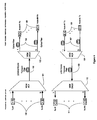
FIG. 4 is a block schematic view of a LDWDM (low dispersion wavelength division multiplexing) network, representing an embodiment of the invention. -
FIG. 5 is a block schematic view of a bi-directional LDWDM (low dispersion wavelength division multiplexing) network, representing an embodiment of the invention. -
FIG. 6 is a block schematic view of a unidirectional LDWDM (low dispersion wavelength division multiplexing) network, representing an embodiment of the invention. -
FIG. 7 is a block schematic view of a bi-directional O-Band DWDM network with legacy CWDM/DWDM, representing an embodiment of the invention. -
FIG. 8 is a block schematic view of a bi-directional LDWDM (low dispersion wavelength division multiplexing) network employing optical amplifiers, representing an embodiment of the invention. -
FIG. 9 is a block schematic view of a three channel LDWDM (low dispersion wavelength division multiplexing) optical frequency plan, representing an embodiment of the invention. - Embodiments of the invention and the various features and advantageous details thereof are explained more fully with reference to the nonlimiting embodiments that are illustrated in the accompanying drawings and detailed in the following description. Descriptions of well known starting materials, processing techniques, components and equipment are omitted so as not to unnecessarily obscure the embodiments of the invention in detail. It should be understood, however, that the detailed description and the specific examples, while indicating preferred embodiments of the invention, are given by way of illustration only and not by way of limitation. Various substitutions, modifications, additions and/or rearrangements within the spirit and/or scope of the underlying inventive concept will become apparent to those skilled in the art from this disclosure.
- The invention presented here solves the problem of cost-effectively expanding bandwidth capacity in fiber-scarce HFC networks by transporting multiple wavelengths over a single fiber using a DWDM system whose wavelengths are densely clustered close to the zero dispersion wavelength of the transport fiber. In SMF-28 and equivalent fibers, which are predominant in access HFC networks, such wavelengths lie in the O-Band (1260nm - 1360nm). In addition to this particularly important application, the invention is generally applicable to the use of wavelength division multiplexing near the zero-dispersion wavelength of any fiber, including, but not limited to, dispersion shifted and other fibers whose zero-dispersion wavelength lies in different spectral regions. Such a system will be referred to here as LDWDM (low dispersion wavelength division multiplexing) to distinguish it from other WDM technologies.
- A WDM system operating in a low-dispersion spectral region (LDWDM) is distinctly different from other WDM technologies, such as CWDM and C-Band and L-Band DWDM that operate far from the zero dispersion wavelength of the fiber. It can be seen from
Figures 1 ,2 and3 that by clustering several wavelengths near the zero-dispersion wavelength of the transport fiber (for SMF-28 or equivalent fiber, this is approximately 1311 nm), the problems of SRS-induced crosstalk and dispersion/chirp-induced CSO that plague other WDM technologies are greatly ameliorated. Because an LDWDM system operates close to the zero dispersion wavelength of the fiber, a wide variety of signals, including RF SCM analog video, RF SCM quasi-analog signals such as M-QAM and N-VSB, and digital signals such as SONET, GbE, 10GbE, FC-1, FC-2, FC-10, etc., can be transported on multiple DWDM wavelengths over a single fiber without the need for significant restrictions on laser transmitter chirp. Consequently, either externally-modulated or directly-modulated laser transmitters can be used in an LDWDM system. However, the major advantage provided by this invention is the ability to use low-cost, directly modulated lasers with constraints on laser chirp that do not differ significantly from those placed on 1310 nm directly-modulated DFB lasers that are used in current generation transmitters. - In contrast to LDWDM, competing WDM technologies such as CWDM or C-Band and L-Band DWDM that transport analog or quasi-analog signals using directly-modulated DFB laser transmitters operating at wavelengths far from the zero-dispersion wavelength of the fiber must restrict the type or the bandwidth of signals they transport, the number of usable wavelengths, or the transport distance in the fiber. For example, over SMF-28 or equivalent type fiber, C-Band and L-Band DWDM directly-modulated laser transmitters can carry only QAM and digital signals with strict frequency allocation rules. In the case of CWDM directly-modulated laser transmitters operating over SMF-28 fiber, the number of wavelengths that can be carried on a single fiber is greatly reduced and severe restrictions are imposed on laser chirp and fiber distances. Alternative technologies and systems using very low chirp transmitters (for example, externally modulated transmitters or ECL-based transmitters) are too expensive for many commercial applications.
- As indicated above, the invention, referred to here as LDWDM, is a wavelength division multiplexed communication system designed and optimized to operate with multiple wavelengths in close proximity to the zero dispersion wavelength of the transport fiber. By way of example, a particularly simple embodiment of such an LDWDM system is shown schematically in
Figure 4 . The system includes separate, unidirectional upstream and downstream links. The downstream link is comprised ofN (where N ≥ 2)laser transmitters 100, each at a distinct wavelength selected from an optical channel plan (to be described in detail below), whose outputs are combined by anoptical multiplexer 101 onto atransport fiber 102 and then separated into individual wavelengths by anoptical demultiplexer 103. Each wavelength is delivered byoptical fiber 104 to areceiver 105. Eachreceiver 105 may be located near theoptical demultiplexer 103, or may be located some distance away, such as in remote nodes or terminals. -
Downstream laser transmitters 100 may be located with theoptical multiplexer 101 in a headend, hub, central office, or other similar signal processing facility, or thedownstream laser transmitters 100 andoptical multiplexer 101 may be functionally distributed among several headends, hubs, central offices, or similar signal processing facilities. The downstreamoptical demultiplexer 103 may be located in a hub or a remote facility such as a node, fiber splice enclosure, fiber management cabinet, or similar facility, or theoptical demultiplexer 103 may be functionally distributed among several such facilities. Theoptical receivers 105 may be located near theoptical demultiplexer 103 or may be located at various distances from it in remote nodes or terminals. - An upstream link includes M (where M may or may not equal N) return
laser transmitters 106, each at a distinct wavelength selected from an optical channel plan, whose outputs are delivered to the inputs of anoptical multiplexer 108 byoptical fibers 107. Thereturn laser transmitters 106 may be located near theoptical multiplexer 108 or may be located various distances away, such as in remote nodes or terminals. Theoptical multiplexer 108 combines the outputs of thereturn laser transmitters 106 onto atransport fiber 109. The combined wavelengths are separated into individual wavelengths by anoptical demultiplexer 110. Each wavelength is delivered by optical fiber to areturn receiver 111. - The
return laser transmitters 106 may be located in nodes or terminals that may be located near the upstreamoptical multiplexer 108 or remotely from it. The upstreamoptical multiplexer 108 may be located in a hub or a remote facility such as a node, fiber splice enclosure, fiber management cabinet, or similar facility, or theoptical multiplexer 108 may be functionally distributed among several such facilities. Thereturn receivers 111 may be located with theoptical demultiplexer 110 in a headend, hub, central office, or other similar signal processing facility, or thereturn receivers 111 andoptical demultiplexer 110 may be functionally distributed among several headends, hubs, central offices, or similar signal processing facilities. - The preferred embodiment would use directly-modulated DFB laser transmitters because of their cost advantage; however, externally-modulated transmitters may also be used in either link. The
transmitters - The individual wavelength at which each
downstream laser transmitter 100 operates is selected from a set of optical channel wavelengths that are in close proximity to the zero dispersion wavelength of thedownstream transport fibers return laser transmitter 106 is selected from a set of optical channel wavelengths that are in close proximity to the zero dispersion wavelength of theupstream transport fibers transport fibers transmitters 100 would lie in the O-Band. In an embodiment in which thetransport fibers transmitters 100 would lie in the C-Band. Similarly, in an embodiment in which thetransport fibers transmitters 106 would lie in the O-Band. In an embodiment in which thetransport fibers transmitters 106 would lie in the C-Band. - The optical channel center wavelengths, optical channel passbands and optical channel spacings of the
optical multiplexers optical demultiplexers optical multiplexers optical demultiplexers - Other embodiments of LDWDM systems are presented in
Figures 5 - 8 . A block diagram of a bidirectional LDWDM system, where downstream and upstream communication signals are transported on a common transport fiber, is presented inFigure 5 . The outputs of Ndownstream laser transmitters 150, each at a distinct wavelength or frequency selected from an optical channel plan, are combined onto a bidirectionaloptical transport fiber 152 by a bidirectional optical multiplexer/demultiplexer (mux/demux) 151. - Of the N downstream optical carriers, J optical carriers are separated into individual wavelengths or frequencies by a bidirectional optical mux/
demux 153. Each of the J downstream optical carriers separated at the bidirectional mux/demux is carried by separateoptical fibers downstream receivers - The remaining N-J optical carriers are directed to the pass-through
port 154 of the bidirectional mux/demux 153 and carried bybidirectional transport fibers drop multiplexers downstream receivers - The outputs ofN-J
return laser transmitters drop multiplexers bidirectional transport fibers port 154 of the bidirectional optical mux/demux 153. - The outputs of the J
return laser transmitters return laser transmitters demux 153 onto thebidirectional transport fiber 152. The bidirectional optical mux/demux 151 separates the N return optical carriers by individual wavelengths and delivers them to correspondingreturn receivers 190. - The
downstream laser transmitters 150, the bidirectional mux/demux 151, and thereturn receivers 190 may typically be located in a headend, hub, central office, or similar signal processing facility. Thedownstream receivers - The preferred embodiment would use directly-modulated DFB laser transmitters because of their cost advantage; however, externally-modulated transmitters may also be used in any link. The
transmitters - The individual wavelengths at which each
downstream laser transmitter 150 and eachreturn laser transmitter bidirectional transport fibers bidirectional transport fibers transmitters bidirectional transport fibers transmitters - The optical channel center wavelengths, optical channel passbands and optical channel spacings of the bidirectional optical mux/
demuxes drop multiplexers demuxes drop multiplexers - The block diagram of a unidirectional LDWDM system with distributed optical multiplexing and demultiplexing is presented in
Figure 6 . The system includes separate, unidirectional upstream and downstream links. The downstream link is comprised ofN (where N ≥ 2)laser transmitters 200, each at a distinct wavelength selected from an optical channel plan, whose outputs are combined by an optical multiplexer (mux) 201 onto atransport fiber 202. An optical demultiplexer (demux) 203 separates J optical carriers into individual wavelengths and delivers them byoptical fibers downstream receivers - The remaining N-J optical carriers are directed to the pass-through
port 204 and carried bytransport fibers drop multiplexers downstream receivers - The outputs of N-J
return laser transmitters drop multiplexers transport fibers port 234 ofoptical multiplexer 250. - The outputs of J
return laser transmitters return laser transmitters optical multiplexer 250 onto thetransport fiber 246. Theoptical demux 247 separates the N return optical carriers by individual wavelength and delivers them to returnreceivers 248. - The
downstream receivers return laser transmitters optical demux 203 and the upstreamoptical multiplexer 250 may be jointly or separately located in hubs or remote facilities such as nodes, fiber splice enclosures, fiber management cabinets, or similar facilities. The optical add/drop multiplexers downstream transmitters 200 and thereturn receivers 248 may be located with the downstreamoptical multiplexer 201 and the upstreamoptical demultiplexer 247 in a headend, hub, central office, or other similar signal processing facility, or thedownstream transmitters 200, thereturn receivers 248, the downstreamoptical multiplexer 201 and the upstreamoptical demultiplexer 247 may be functionally distributed among several headends, hubs, central offices, or similar signal processing facilities. - The preferred embodiment would use directly-modulated DFB laser transmitters because of their cost advantage; however, externally-modulated transmitters may also be used in either link. The
transmitters - The individual wavelength at which each
downstream laser transmitter 200 operates is selected from a set of optical channel wavelengths that are in close proximity to the zero dispersion wavelength of thedownstream transport fibers return laser transmitter upstream transport fibers transport fibers transmitters 200 would lie in the O-Band. In an embodiment in which thetransport fibers transmitters 200 would lie in the C-Band. Similarly, in an embodiment in which thetransport fibers transmitters transport fibers transmitters - The optical channel center wavelengths, optical channel passbands and optical channel spacings of the
optical multiplexers optical demultiplexers drop multiplexers optical multiplexers optical demultiplexers drop multiplexers - O-Band LDWDM systems may be combined with appropriate sets of CWDM or C-Band DWDM optical channels in many possible embodiments.
Figure 7 presents a block diagram of a bidirectional "mixed" system of O-Band optical carriers and "legacy" CWDM or DWDM optical carriers. The outputs of N-J (where N-J ≥ 1) CWDM/DWDM laser transmitters 301 are combined by a CWDM/DWDM bidirectional optical mux/demux 303, whose common port is connected to the pass-throughport 305 of an appropriately designed bidirectional O-Band optical mux/demux 302. - The O-Band bidirectional mux/
demux 302 then combines the N-J CDWM or DWDM transmitter outputs with the outputs of J (where J ≥ 2) O-Band laser transmitters 300, each at a distinct wavelength or frequency selected from an O-Band optical channel plan, onto a commonbidirectional transport fiber 306. Downstream O-Band carriers are separated into individual wavelengths by an appropriately designed O-Band bidirectional optical mux/demux 307 and directed by optical fiber todownstream receivers 309, which may be located in remote nodes or terminals. - The remaining group of downstream CWDM/DWDM optical carriers are directed through the pass-through
port 308 of the bidirectional optical mux/demux 307 to atransport fiber 310 and into the common port of a CWDM /DWDM bidirectional optical mux/demux 311. The CWDM /DWDM bidirectional mux/demux 311 then separates the CWDM/DWDM optical carriers into individual wavelengths and directs them via optical fiber todownstream receivers 312, which may be located in remote nodes or terminals. - The outputs ofN-J CWDM/DWDM
return laser transmitters 320, which may be located in remote nodes or terminals, are combined by the CWDM/DWDM bidirectional optical mux/demux 311 onto abidirectional transport fiber 310 and into the O-Band bidirectional mux/demux 307 via the pass-throughport 308. - The O-Band bidirectional mux/
demux 307 combines the CWDM/DWDM optical carriers with the outputs of J O-Band return transmitters 321, each at a distinct frequency selected from an O-Band optical channel plan, onto a commonbidirectional transport fiber 306. - The O-Band bidirectional mux/
demux 302 separates the J O-Band optical carriers into individual wavelengths and directs them to returnreceivers 322. The CWDM/DWDM optical carriers are directed through the pass throughport 305 of the O-Band bidirectional mux/demux 320 to a bidirectional CWDM/DWDM mux/demux that separates the CWDM/DWDM upstream optical carriers into distinct wavelengths and directs them to returnreceivers 323. - The
downstream laser transmitters demuxes demuxes - The preferred embodiment would use directly-modulated DFB O-
Band laser transmitters - The optical channel center wavelengths, optical channel passbands and optical channel spacings of the bidirectional optical mux/
demuxes demuxes - Appropriate optical amplification technology may also be used with LDWDM systems, as shown by the embodiment presented in
Figure 8 , and optically amplified bidirectional LDWDM system. The outputs ofNdownstream laser transmitters 401, each at a distinct wavelength or frequency selected from an optical frequency channel plan, are amplified byoptical amplifiers 402 and combined onto a common bidirectionaloptical transport fiber 404 by a bidirectional optical multiplexer/demultiplexer (mux/demux) 403. - Of the N downstream optical carriers, J optical carriers are separated into individual wavelengths or frequencies by a bidirectional optical mux/
demux 405. Each of the J downstream optical carriers separated at the bidirectional mux/demux is carried by optical fibers to correspondingdownstream receivers 407, which may be located in remote nodes or terminals. - The remaining N-J optical carriers are directed to the pass-through
port 406 of the bidirectional mux/demux 405 and carried bybidirectional transport fibers drop multiplexers downstream receivers 407, which may be located in remote nodes or terminals. - The outputs of N-J
return laser transmitters 416, each at a distinct wavelength or frequency selected from an optical channel plan, and which may be optically amplified by anoptical amplifier 417, are then multiplexed by a cascade of bidirectional optical add/drop multiplexers bidirectional transport fibers port 406 of the bidirectional optical mux/demux 405. - The outputs of the J
return laser transmitters 416, each at a distinct optical frequency or wavelength selected from an optical channel plan, are multiplexed with the outputs of the N-Jreturn laser transmitters 416 by the bidirectional optical mux/demux 405 onto thebidirectional transport fiber 404. The bidirectional optical mux/demux 403 separates the N return optical carriers by individual wavelengths and delivers them to correspondingreturn receivers 418. - The
downstream laser transmitters 401, the bidirectional mux/demux 403, and thereturn receivers 418 may typically be located in a headend, hub, central office, or similar signal processing facility. Thedownstream receivers 407 and thereturn transmitters 416 may typically be located in optical nodes or remote terminals. - The preferred embodiment would use directly-modulated DFB laser transmitters because of their cost advantage; however, externally-modulated transmitters may also be used in any link. The
transmitters - The individual wavelengths at which each
downstream laser transmitter 401 and eachreturn laser transmitter 416 operates is selected from a set of optical channel wavelengths that are in close proximity to the zero dispersion wavelength of thetransport fibers transport fibers transmitters Optical amplifiers transport fibers transmitters optical amplifiers - The optical channel center wavelengths, optical channel passbands and optical channel spacings of the bidirectional optical mux/
demuxes drop multiplexers demuxes drop multiplexers - The embodiments described above are provided by way of example. Other embodiments are possible, and are not limited to those specifically described here.
- Optical channel plans for low-dispersion-regime DWDM systems (LDWDM) must be optimized against several competing constraints. While operation close to the zero-dispersion wavelength using narrow channel spacing alleviates the problems of SRS-induced crosstalk and dispersion/chirp-induced CSO, other types of crosstalk caused by fiber nonlinearities such as XPM and 4WM become dominant for small channel spacing in this spectral region of the optical fiber.
- XPM arises when the power in one modulated wavelength channel induces a small change in the refractive index of the fiber (through the nonlinear refractive index), which in turn induces a phase modulation (PM) on the other wavelengths. Chromatic dispersion in the fiber then converts this phase modulation to intensity modulation (IM). The PM to IM conversion causes some amount of the modulated signal on one optical carrier to appear on other optical carriers, i.e. crosstalk. Since chromatic dispersion is necessary for XPM crosstalk, XPM crosstalk near the zero-dispersion wavelength is negligible.
- In the general case of four-wave mixing (4WM), lightwaves at two or more distinct frequencies propagating in the optical fiber can interact through the third-order nonlinear optical susceptibility to create lightwaves at other frequencies. This mixing process can produce lightwaves at all possible sum and difference frequency combinations, although light at many of the possible frequency mixing terms will not be produced in any significant quantity because the phase-matching requirements of this traveling-wave process will not be satisfied in the fiber. The frequency mixing terms of concern are those that lie in proximity to the zero-dispersion wavelength of the fiber and are phase-matched for the mixing interaction - these frequency mixing products are all of the form fi+fj-fk, where k is distinct from i or j. This situation is directly analogous to the composite triple-beat (CTB) problem of the RF carrier spectrum of analog video transport, where intermodulation products are generated within the carrier spectrum. As mentioned previously, HFC access networks have historically used SMF-28 or equivalent fibers. In these fibers, the zero-dispersion wavelength is located at approximately 1311 nm in O-Band but the invention applies to any DWDM system with directly modulated DFB transmitters with wavelengths located in proximity to the zero-dispersion wavelength of the fiber used.
- As described above, the frequencies of the in-band (optical) four-wave mixing products are given by:

- Thus, in a DWDM system with N wavelengths present, the total number of four-wave mixing products, M, is given by:

- For example, there are nine mixing products for N=3, 24 mixing products for N=4 and 450 mixing products for N=10.
- lf one of the mixing products occurs at the same optical frequency as an existing DWDM channel the result is 4WM crosstalk. Since M increases as N3, it becomes extremely difficult to avoid 4WM crosstalk as N increases above 10.
- In a DWDM system with three equally-spaced signals at optical frequencies f1, f2, and f3 there are nine mixing products: f113, f112, f123, f223, f132, f221, f332, f231, and f331. However, because of their equal spacing, note that f223 = f2+ (f2-f3) = f1, and similarly f132=f2, f312 = f2 and f221 = f3. That is, 4 WM crosstalk is inevitable if there are three or more equally spaced channels in the DWDM system.
- Equally spaced channels would therefore be employed only with large channel spacings and/or at wavelengths far from the zero-dispersion wavelength so that four-wave mixing products are sufficiently weak due to lack of phase-matching. It may also be possible to use equally spaced channels by restricting analog video to be the same for all wavelengths (for broadcast applications) and allow only the narrowcast QAM channels, which are more robust to crosstalk, to differ.
- Efficient generation of four-wave mixing products require the signals to stay in phase (phase-matching) with each other over as long an interaction length as possible. Fiber dispersion results in temporal walk-offdue to group-velocity mismatch and a corresponding decrease in the effective interaction length. Consequently, mixing efficiency - the ratio of power in the mixing products to the input channel power - decreases rapidly for wavelengths that differ from the zero-dispersion wavelength by even a few nm.
- In the presence of dispersion, mixing efficiency can also be reduced by increasing DWDM channel spacing. Mixing efficiency is also very sensitive to optical power levels, having a 20 log(P) dependence on DWDM channel power. In long-haul networks, 4WM is minimized by dispersion management whereby fiber spools with positive and negative dispersion are alternated to achieve a net dispersion of zero while maintaining a non-zero dispersion at all points of the fiber link. This technology, however, cannot be used in short optical access links with sub-carrier-multiplexed (SCM) analog video and QAM-modulated RF signals transporting video, voice, and data due to limited loss budget over which these links operate and lack of cost-effective optical amplification technology for this application.
- Analog video transmission can tolerate only extremely low levels of crosstalk. Reduction of crosstalk to acceptably low levels can be achieved by the following 4WM crosstalk suppression techniques: operation at wavelengths slightly offset from the fiber zero-dispersion wavelength and the use of unequal optical channel spacings. Although this is bandwidth inefficient, most WDM systems use channel spacing much larger than the bandwidth of the signals. Unequal channel spacing uses some of this "waisted bandwidth" to place 4WM products away from the channels. Note that it is not sufficient for the mixing products to be offset from the WDM channels; the offset of the mixing products from the WDM channels must be larger than the passband of the WDM filters used for multiplexing and demultiplexing. Mixing products can be guaranteed not to fall on WDM channels by requiring the difference between any two channel frequencies to be unique.
- Note that this requirement makes LDWDM systems distinctly different in optical carrier frequency assignment than CWDM per ITU G.694.2 and DWDM systems with wavelengths located at larger separations from the zero-dispersion frequency of the fiber (for example, Land C-Band DWDM systems per ITU G.6941 deployed on SMF-28 or equivalent fibers).
- Prior to this invention, the challenge presented by distortion and crosstalk due to linear and nonlinear optical fiber effects on RF SCM analog video and RF QAM carriers has prevented the development and deployment of a multi-wavelength system operating in proximity to the zero-dispersion wavelength of single mode optical fiber with full RF channel load from the lowest to the highest forward frequency of SCM systems (typically used in, but not limited to, cable TV applications with frequency range from 50 to 1002 MHz in North America, 65 to 1002 MHz in Japan and from 85 to 1002 MHz in Europe). The main characteristic of the fully loaded signal spectrum with SCM analog and QAM channels is that the RF load occupies several octaves of the RF spectrum. Specifically, for SMF-28 or equivalent type optical fiber (which historically has been the predominantly deployed fiber in HFC access plant), there has been no development and deployment of a multi-wavelength system operating in O-Band in the proximity to the zero-dispersion wavelength of this fiber at 1311 nm wavelength.
- Many particular embodiments of optical frequency channel plans for low-dispersion dense wavelength division multiplex systems (LDWDM) are possible, depending upon how competing constraints are balanced. However, optical frequency channel plans can be described generally by characteristic features and constraints. First, it should be noted that any set of segments of a given fiber type, such as SMF-28 or an equivalent, will exhibit a range of zero-dispersion frequencies from f0,min to f0,max about a central or average value of zero-dispersion frequency f0; this range may be defined by the absolute limits of the manufacturers' specifications or statistically by a characteristic width of a distribution function describing the set of zero-dispersion frequency values in a given set of fiber lengths. Typically deployed fiber links are composed of many fiber segments that are spliced together.
- The basic characteristic of an LDWDM optical frequency channel plan is the use of multiple optical carriers whose frequencies lie as close as possible to the average value of the zero-dispersion frequency (or wavelength) of a fiber link, or near either the low frequency or high frequency edge of the range of zero-dispersion frequencies as described above, subject to the constraints necessary to reduce crosstalk effects. The use of optical transmission carrier frequencies near the zero-dispersion frequency, or range of zero-dispersion frequencies, of a given fiber type, such as O-Band wavelengths for SMF-28 or equivalent fiber, greatly reduces dispersion-induced distortions. This in turn allows the use of directly modulated DFB lasers, without severe restrictions on the value of the chirp parameter of such lasers, to transport multi-octave RF SCM analog video and quasi-analog QAM video, voice, and data signals. Using optical channel frequencies near the average zero-dispersion frequency of a transport fiber also reduces the crosstalk due to XPM, as discussed above.
- Although not strictly necessary, a minimum frequency (or wavelength) separation may be chosen for convenience to define a frequency grid - typically, but not limited to, 10 GHz, 50 GHz, 100 GHz, or 200GHz. The choice of a particular minimum frequency separation may be determined in part by the specifications of the optical multiplexers, optical demultiplexers and optical add/drop multiplexers. Specific optical transmission frequencies can be selected on such a grid to meet the constraints that minimize crosstalk and distortion.
- The primary constraint on the selection of optical channel frequencies is that the frequency difference between any two optical carriers be unique. This produces a non-uniformly spaced set of optical channels whose four-wave mixing products do not fall on the selected channel frequencies.
- Four wave mixing effects may be further reduced by choosing all optical channel transmission frequencies to be greater than the maximum zero dispersion frequency or less than the minimum zero dispersion frequency of the set of all fiber segments comprising an optical fiber link. This condition disrupts phase-matching of the four wave mixing process by allowing the optical carriers to experience small amounts of dispersion. In some embodiments, adequate reduction of four wave mixing effects may be obtained by requiring that all optical carrier frequencies be greater than the maximum zero dispersion frequency or less than the minimum zero dispersion frequency of the fiber segment or segments comprising the first 2.5 km or first 5 km of the fiber link. Such conditions reduce phase-matching of the four wave mixing process in the section of the optical fiber link where the optical power levels that drive the four wave mixing process are greatest.
- Additional reductions in four wave mixing effects may be obtained by maximizing the frequency difference between the two optical carriers that are closest to the average zero-dispersion frequency of the transport fiber, again by disruption of phase-matching.
- The optical frequency difference between any two optical carriers should be as great as possible to minimize XPM-driven crosstalk.
- For a given number of optical carriers, the frequency difference between the highest and lowest frequencies of the optical carriers should be minimized to reduce SRS-induced crosstalk.
- By way of example, a particular embodiment of an LDWDM optical frequency plan with three optical carriers is presented schematically in
Figure 9 . On a horizontal axis that represents a range of optical frequencies, the average zerodispersion frequency f 0 700 is shown, along with a range of zero dispersion frequencies f0, min to f0, max. A firstoptical carrier 703 is established at frequency f1 with a frequency separation ofΦ 701 from the average zerodispersion frequency f 0 700. With a minimum frequency separation ofΔ 702, a secondoptical carrier 704 is established at f2, where f2 = f1 + 4Δ. A thirdoptical carrier 705 is established at f3, where f3 = f1 + 9Δ. These three optical carriers produce 9 four-wave mixing products 706 at frequencies f1 - 9Δ, f1 - 5Δ, f1 - 4A, f1 - Δ, f1 + 5Δ, f1 + 8Δ, f1 + 13Δ, f1 + 14Δ, and f1 + 18Δ. Pass-band widths of optical multiplexers, optical demultiplexers, optical add/drop multiplexers, and optical filters would be chosen to reject the four-wave mixing products 706 during multiplexing or demultiplexing. Note that no vertical scale is implied inFigure 9 . - Many other embodiments of optical frequency channel plans are possible. Different multiples of different minimum frequency separations can be used to establish different optical carrier frequencies. Optical carrier frequency plans may be translated with respect to the average zero dispersion frequency of the transport fiber, optical carrier frequency plans may be "inverted" or "mirrored" about any specific frequency, and optical carrier frequency plans may be produced by the combination of frequency translation and inversion.
- The term program and/or the phrase computer program are intended to mean a sequence of instructions designed for execution on a computer system (e.g., a program and/or computer program, may include a subroutine, a function, a procedure, an object method, an object implementation, an executable application, an applet, a servlet, a source code, an object code, a shared library/dynamic load library and/or other sequence of instructions designed for execution on a computer or computer system). The term substantially is intended to mean largely but not necessarily wholly that which is specified. The term approximately is intended to mean at least close to a given value (e.g., within 10% of). The term generally is intended to mean at least approaching a given state. The term coupled is intended to mean connected, although not necessarily directly, and not necessarily mechanically. The term proximate, as used herein, is intended to mean close, near adjacent and/or coincident; and includes spatial situations where specified functions and/or results (if any) can be carried out and/or achieved. The term distal, as used herein, is intended to mean far, away, spaced apart from and/or non-coincident, and includes spatial situation where specified functions and/or results (if any) can be carried out and/or achieved. The term deploying is intended to mean designing, building, shipping, installing and/or operating.
- The terms first or one, and the phrases at least a first or at least one, are intended to mean the singular or the plural unless it is clear from the intrinsic text of this document that it is meant otherwise. The terms second or another, and the phrases at least a second or at least another, are intended to mean the singular or the plural unless it is clear from the intrinsic text of this document that it is meant otherwise. Unless expressly stated to the contrary in the intrinsic text of this document, the term or is intended to mean an inclusive or and not an exclusive or. Specifically, a condition A or B is satisfied by any one of the following: A is true (or present) and B is false (or not present), A is false (or not present) and B is true (or present), and both A and B are true (or present). The terms a and/or an are employed for grammatical style and merely for convenience.
- The term plurality is intended to mean two or more than two. The term any is intended to mean all applicable members of a set or at least a subset of all applicable members of the set. The term means, when followed by the term "for" is intended to mean hardware, firmware and/or software for achieving a result. The term step, when followed by the term "for" is intended to mean a (sub)method, (sub)process and/or (sub)routine for achieving the recited result.
- The terms "comprises," "comprising," "includes," "including," "has," "having" or any other variation thereof, are intended to cover a non-exclusive inclusion. For example, a process, method, article, or apparatus that comprises a list of elements is not necessarily limited to only those elements but may include other elements not expressly listed or inherent to such process, method, article, or apparatus. The terms "consisting" (consists, consisted) and/or "composing" (composes, composed) are intended to mean closed language that does not leave the recited method, apparatus or composition to the inclusion of procedures, structure(s) and/or ingredient(s) other than those recited except for ancillaries, adjuncts and/or impurities ordinarily associated therewith. The recital of the term "essentially" along with the term "consisting" (consists, consisted) and/or "composing" (composes, composed), is intended to mean modified close language that leaves the recited method, apparatus and/or composition open only for the inclusion of unspecified procedure(s), structure(s) and/or ingredient(s) which do not materially affect the basic novel characteristics of the recited method, apparatus and/or composition.
- Unless otherwise defined, all technical and scientific terms used herein have the same meaning as commonly understood by one of ordinary skill in the art to which this invention belongs. In case of conflict, the present specification, including definitions, will control.
- The described embodiments and examples are illustrative only and not intended to be limiting. Although embodiments of the invention can be implemented separately, embodiments of the invention may be integrated into the system(s) with which they are associated. All the embodiments of the invention disclosed herein can be made and used without undue experimentation in light of the disclosure. Although the best mode of the invention contemplated by the inventor(s) is disclosed, embodiments of the invention are not limited thereto. Embodiments of the invention are not limited by theoretical statements (if any) recited herein. The individual steps of embodiments of the invention need not be performed in the disclosed manner, or combined in the disclosed sequences, but may be performed in any and all manner and/or combined in any and all sequences. The individual components of embodiments of the invention need not be formed in the disclosed shapes, or combined in the disclosed configurations, but could be provided in any and all shapes, and/or combined in any and all configurations. The individual components need not be fabricated from the disclosed materials, but could be fabricated from any and all suitable materials. Homologous replacements may be substituted for the substances described herein. Agents which are both chemically and physiologically related may be substituted for the agents described herein where the same or similar results would be achieved.
- It can be appreciated by those of ordinary skill in the art to which embodiments of the invention pertain that various substitutions, modifications, additions and/or rearrangements of the features of embodiments of the invention may be made without deviating from the spirit and/or scope of the underlying inventive concept. All the disclosed elements and features of each disclosed embodiment can be combined with, or substituted for, the disclosed elements and features of every other disclosed embodiment except where such elements or features are mutually exclusive. The scope of the underlying inventive concept as defined by the appended claims and their equivalents cover all such substitutions, modifications, additions and/or rearrangements.
- The appended claims are not to be interpreted as including means-plus-function limitations, unless such a limitation is explicitly recited in a given claim using the phrase(s) "means for" and/or "step for." Subgeneric embodiments of the invention are delineated by the appended independent claims and their equivalents. Specific embodiments of the invention are differentiated by the appended dependent claims and their equivalents.
Claims (7)
- A method, comprising transporting a plurality of optical carriers of different wavelengths over an optical link using wavelength division multiplexing, the optical link including a plurality of optical segments, wherein a plurality of optical channel center wavelengths defined by the plurality of optical carriers are clustered proximate an average value of zero-dispersion wavelength of the optical link, or near either a) a low wavelength edge or b) a high wavelength edge of a range of zero-dispersion wavelengths of the optical link, the range defmed i) by absolute limits of manufacturers' specifications or ii) statistically by a characteristic width of a distribution function describing a set of zero-dispersion frequency values in the plurality of optical segments, and wherein a plurality of optical channel center frequencies defined by the plurality of optical channel center wavelengths are non-uniformly spaced apart,
wherein the plurality of optical carriers of different wavelengths transport at least one signal selected from the group comprising radio frequency RF) sub-carrier-multiplexed (SCM) analog and radio frequency (RF) sub-carrier-multiplexed (SCM) quasi-analog signals; and
wherein all the plurality of optical channel center frequencies are a) greater than a maximum zero dispersion frequency or b) less than the minimum zero dispersion frequency of all the optical segments to disrupt phase-matching with regard to four wave mixing by allowing all the plurality of optical carriers to experience small amounts of dispersion. - The method of claim 1, where all differences between all of the plurality of optical channel center frequencies are unique to produce a non-uniformly spaced set of optical channel center frequencies whose four-wave mixing products are not equal to one of more of the plurality of the optical channel center frequencies.
- The method of claim 1, wherein optical channel frequencies of the optical carriers are multiples of a minimal frequency separation.
- The method of claim 1, wherein all of the plurality of optical channel center wavelengths are clustered within 50 nm of the zero-dispersion wavelength of the transport fiber.
- The method of claim 1, wherein spacings between the plurality of optical channel wavelengths are from approximately 0.5 nm to approximately 20nm.
- The method of claim 1, wherein the RF SCM quasi-analog signals are RF QAM signals, and preferably RF SCM M-QAM signals.
- An apparatus, comprising a low dispersion wavelength division multiplexing network transporting a plurality of optical carriers of different wavelengths using a wavelength division multiplexing, the low dispersion wavelength division multiplexing network including: an optical multiplexer (403, 405) ; an optical link coupled to the multiplexer, the optical link including a plurality of optical segments; and an optical demultiplexer (403, 405) coupled to the optical link, wherein a plurality of optical channel center wavelengths defined by the plurality of optical carriers are clustered proximate an average value of a zero-dispersion wavelength of the optical link, or near either a) a low wavelength edge or b) a high wavelength edge of a range of zero-dispersion wavelengths of the optical link, the range defined i) by absolute limits of manufacturers' specifications or ii) statistically by a characteristic width of a distribution function describing a set of zero-dispersion frequency values in the plurality of optical segments, and wherein a plurality of optical channel center frequencies defined by the plurality of optical channel center wavelengths are non-uniformly spaced apart,
wherein the plurality of optical carriers of different wavelengths transport at least one signal selected from the group comprising radio frequency (RF) sub-carrier-multiplexed (SCM) analog and radio frequency sub-carrier-multiplexed quasi-analog signals; and
wherein all the plurality of optical channel center frequencies are a) greater than a maximum zero dispersion frequency or b) less than the minimum zero dispersion frequency of all the optical segments to disrupt phase-matching with regard to four wave mixing by allowing all the plurality of optical carriers to experience small amounts of dispersion.
Applications Claiming Priority (3)
| Application Number | Priority Date | Filing Date | Title |
|---|---|---|---|
| US81058606P | 2006-06-02 | 2006-06-02 | |
| US92382707P | 2007-04-16 | 2007-04-16 | |
| PCT/US2007/013185 WO2007149213A2 (en) | 2006-06-02 | 2007-06-04 | Dwdm transport of catv and digital signals over optical fiber in low-dispersion spectral regions |
Publications (2)
| Publication Number | Publication Date |
|---|---|
| EP2033349A2 EP2033349A2 (en) | 2009-03-11 |
| EP2033349B1 true EP2033349B1 (en) | 2011-10-26 |
Family
ID=38670678
Family Applications (1)
| Application Number | Title | Priority Date | Filing Date |
|---|---|---|---|
| EP07845253A Not-in-force EP2033349B1 (en) | 2006-06-02 | 2007-06-04 | Wdm transport of sub-carrier-multiplexed signals over an optical fiber in low-dispersion spectral regions |
Country Status (5)
| Country | Link |
|---|---|
| US (1) | US8213797B2 (en) |
| EP (1) | EP2033349B1 (en) |
| AT (1) | ATE531149T1 (en) |
| CA (1) | CA2657196C (en) |
| WO (1) | WO2007149213A2 (en) |
Cited By (1)
| Publication number | Priority date | Publication date | Assignee | Title |
|---|---|---|---|---|
| US20240089004A1 (en) * | 2022-09-08 | 2024-03-14 | Marvell Asia Pte Ltd | Reduction of four-wave mixing crosstalk in optical links |
Families Citing this family (19)
| Publication number | Priority date | Publication date | Assignee | Title |
|---|---|---|---|---|
| WO2007149213A2 (en) * | 2006-06-02 | 2007-12-27 | Aurora Networks, Inc. | Dwdm transport of catv and digital signals over optical fiber in low-dispersion spectral regions |
| US8417117B2 (en) * | 2006-10-10 | 2013-04-09 | Alcatel Lucent | DWDM and CWDM hybrid PON system and method |
| US8503881B1 (en) * | 2007-04-06 | 2013-08-06 | University Of Central Florida Research Foundation, Inc. | Systems for extending WDM transmission into the O-band |
| US20090010649A1 (en) * | 2007-07-02 | 2009-01-08 | Tellabs Bedford, Inc. | Optical access network with legacy support |
| US9065964B1 (en) * | 2009-08-17 | 2015-06-23 | Arris Enterprises, Inc. | Reducing four wave mixing ingress |
| US8538516B2 (en) * | 2009-09-24 | 2013-09-17 | Chong Il Lee | Method and system to address multiple electrodes for sensing and stimulation in brain and heart |
| US9521464B2 (en) | 2010-01-22 | 2016-12-13 | Gainspeed, Inc. | HFC cable system with alternative wideband communications pathways and coax domain amplifier-repeaters |
| US8826359B2 (en) | 2010-01-22 | 2014-09-02 | Gainspeed, Inc. | HFC cable system with shadow fiber and coax fiber terminals |
| US8863213B2 (en) | 2010-01-22 | 2014-10-14 | Gainspeed, Inc. | Methods of adaptive cancelling and secondary communications channels for extended capability HFC cable systems |
| US8509621B2 (en) * | 2010-02-16 | 2013-08-13 | Ciena Corporation | Method and system for optical connection validation |
| US20120213515A1 (en) * | 2011-02-18 | 2012-08-23 | Zoran Maricevic | Service group aggregation |
| US9923751B2 (en) | 2011-07-01 | 2018-03-20 | Arris Enterprises Llc | Overlay system with digital optical transmitter for digitized narrowcast signals |
| WO2013126297A1 (en) * | 2012-02-20 | 2013-08-29 | Shlomo Rakib | Methods of adaptive cancelling and secondary communications channels for extended capability hfc cable systems |
| US8731400B2 (en) * | 2012-04-09 | 2014-05-20 | Jds Uniphase Corporation | Characterizing a frequency channel in an optical network |
| RU2521045C1 (en) * | 2012-12-27 | 2014-06-27 | Сергей Николаевич Сергеев | Method of setting up duplex links in one fibre using optical signals operating in opposite directions and having same carrier wavelength with retroreflection control |
| US9485049B2 (en) * | 2013-03-29 | 2016-11-01 | Infinera Corporation | Adjusting carrier spacing in a channel |
| ES2690389T3 (en) * | 2014-04-29 | 2018-11-20 | Huawei Technologies Co. Ltd. | Wireless communications system and radio frequency device |
| US9979483B2 (en) * | 2015-04-17 | 2018-05-22 | Aurora Networks, Inc. | Spatially multiplexed receiver for OBI-free multipoint-to-point optical networks |
| CN113872722B (en) * | 2016-08-30 | 2023-09-19 | 菲尼萨公司 | Bidirectional transceiver with time synchronization |
Citations (2)
| Publication number | Priority date | Publication date | Assignee | Title |
|---|---|---|---|---|
| US5430568A (en) * | 1992-12-01 | 1995-07-04 | Scientific-Atlanta, Inc. | Optical communications system for transmitting information signals having different wavelengths over a same optical fiber |
| EP1126638A2 (en) * | 1999-11-29 | 2001-08-22 | Mitsubishi Denki Kabushiki Kaisha | Optical wavelength division multiplexing transmission system |
Family Cites Families (16)
| Publication number | Priority date | Publication date | Assignee | Title |
|---|---|---|---|---|
| CA2139957C (en) * | 1994-02-18 | 1999-02-09 | Andrew R. Chraplyvy | Multi-channel optical fiber communication system |
| US5880865A (en) * | 1996-12-03 | 1999-03-09 | Lucent Technologies Inc. | Wavelength-division-multiplexed network having broadcast capability |
| SE523374C2 (en) * | 1997-07-31 | 2004-04-13 | Ericsson Telefon Ab L M | Communication using spectrum spreading methods over optical fibers |
| CA2321500A1 (en) * | 1998-02-20 | 1999-08-26 | Mci Worldcom, Inc. | Dense wdm in the 1310nm band |
| US6545780B1 (en) * | 1998-04-22 | 2003-04-08 | Nippon Telegraph And Telephone Corporation | Wavelength allocation method, a transmission equipment and receiving equipment using this method and a wavelength division multiplex transmission system |
| US6407842B1 (en) * | 1998-10-28 | 2002-06-18 | Tycom (Us) Inc. | Method and apparatus for transmitting a WDM optical signal having nonuniform channel spacings |
| DE10014003C1 (en) | 2000-03-22 | 2002-09-19 | Ulrich Pitzl | Device for supporting a post, in particular a wooden beam |
| US7120359B2 (en) * | 2000-05-22 | 2006-10-10 | Opvista Incorporated | Broadcast and select all optical network |
| US6895185B1 (en) * | 2000-08-24 | 2005-05-17 | Korea Advanced Institute Of Science And Technology | Multi-purpose optical fiber access network |
| US7085497B2 (en) * | 2002-04-03 | 2006-08-01 | Lockheed Martin Corporation | Vehicular communication system |
| US20040141748A1 (en) * | 2003-01-22 | 2004-07-22 | Ralph Spickermann | Use of coarse WDM channels for upstream traffic in fiber-to-the-home systems |
| US7577367B2 (en) * | 2004-06-15 | 2009-08-18 | Op Vista Incorporated | Optical communication using duobinary modulation |
| KR100754601B1 (en) * | 2006-01-27 | 2007-09-05 | 삼성전자주식회사 | Complex Passive Optical Subscriber Network |
| KR100678024B1 (en) * | 2006-02-10 | 2007-02-02 | 삼성전자주식회사 | Complex Passive Optical Subscriber Network Using Wireless Communication |
| KR100827171B1 (en) * | 2006-05-02 | 2008-05-02 | 삼성전자주식회사 | Optical communication method of subcarrier multiplexing method and passive optical subscriber network using the same |
| WO2007149213A2 (en) * | 2006-06-02 | 2007-12-27 | Aurora Networks, Inc. | Dwdm transport of catv and digital signals over optical fiber in low-dispersion spectral regions |
-
2007
- 2007-06-04 WO PCT/US2007/013185 patent/WO2007149213A2/en not_active Ceased
- 2007-06-04 US US11/810,392 patent/US8213797B2/en not_active Expired - Fee Related
- 2007-06-04 EP EP07845253A patent/EP2033349B1/en not_active Not-in-force
- 2007-06-04 CA CA2657196A patent/CA2657196C/en active Active
- 2007-06-04 AT AT07845253T patent/ATE531149T1/en not_active IP Right Cessation
Patent Citations (2)
| Publication number | Priority date | Publication date | Assignee | Title |
|---|---|---|---|---|
| US5430568A (en) * | 1992-12-01 | 1995-07-04 | Scientific-Atlanta, Inc. | Optical communications system for transmitting information signals having different wavelengths over a same optical fiber |
| EP1126638A2 (en) * | 1999-11-29 | 2001-08-22 | Mitsubishi Denki Kabushiki Kaisha | Optical wavelength division multiplexing transmission system |
Cited By (1)
| Publication number | Priority date | Publication date | Assignee | Title |
|---|---|---|---|---|
| US20240089004A1 (en) * | 2022-09-08 | 2024-03-14 | Marvell Asia Pte Ltd | Reduction of four-wave mixing crosstalk in optical links |
Also Published As
| Publication number | Publication date |
|---|---|
| WO2007149213A3 (en) | 2008-07-17 |
| US8213797B2 (en) | 2012-07-03 |
| ATE531149T1 (en) | 2011-11-15 |
| CA2657196C (en) | 2013-10-08 |
| WO2007149213A2 (en) | 2007-12-27 |
| EP2033349A2 (en) | 2009-03-11 |
| US20070297801A1 (en) | 2007-12-27 |
| CA2657196A1 (en) | 2007-12-27 |
Similar Documents
| Publication | Publication Date | Title |
|---|---|---|
| US8213797B2 (en) | DWDM transport of CATV and digital signals over optical fiber in low-dispersion spectral regions | |
| US6252688B1 (en) | Optical wavelength multiplex transmission method and optical dispersion compensation method | |
| US7831118B2 (en) | Coarse wavelength division multiplexing optical transmission system, and coarse wavelength division multiplexing optical transmission method | |
| Cheng et al. | Flexible TWDM PON system with pluggable optical transceiver modules | |
| US7783197B2 (en) | Method and apparatus for reducing crosstalk in a DWDM transmission system | |
| US20010024542A1 (en) | Method and device for dropping optical channels in an optical transmission system | |
| US6366376B1 (en) | Optical transmitting device using wavelength division multiplexing to transmit signal lights having frequencies arranged to eliminate effects of four-wave mixing (FWM) | |
| EP1088417B1 (en) | Method and device for dropping optical channels in an optical transmission system | |
| JP4002063B2 (en) | Optical wavelength add / drop multiplexer and filter element used therefor | |
| Lee et al. | Hybrid 10-Gb/s, 2.5-Gb/s, 64-QAM, and AM-VSB high-capacity wavelength-division-multiplexing transport systems using SMF and LEAF fibers | |
| US20200177299A1 (en) | Apparatus and method to reduce the impact of coherent crosstalk in optical networks | |
| Lu et al. | A hybrid CATV/256-QAM/OC-48 DWDM system over an 80 km LEAF transport | |
| US6901184B2 (en) | Frequency comb for an optical WDM network | |
| Selvamani et al. | Suppression of four wave mixing by optical phase conjugation in DWDM fiber optic link | |
| JP3757075B2 (en) | OPTICAL NETWORK, OPTICAL TRANSMITTER, OPTICAL RECEIVER, OPTICAL AMPLIFIER, DISPERSION COMPENSATOR, SIGNAL LIGHT WAVELENGTH SELECTION METHOD IN OPTICAL NETWORK, WAVELENGTH MULTIPLEXER | |
| Lu et al. | CSO/CTB performances improvement in a bi-directional DWDM CATV system | |
| US6577424B1 (en) | Chromatic dispersion compensator providing dispersion compensation to select channels of a wavelength division multiplexed signal | |
| JP2006129503A (en) | OPTICAL NETWORK, OPTICAL TRANSMITTER, OPTICAL RECEIVER, OPTICAL AMPLIFIER, DISPERSION COMPENSATOR, SIGNAL LIGHT WAVELENGTH SELECTION METHOD IN OPTICAL NETWORK, WAVELENGTH MULTIPLEXER | |
| Thiele et al. | System margin considerations for cost-effective CWDM access networks | |
| Effenberger | NG-PON: Enabling technologies for metro-access convergence | |
| Osmond et al. | Component serial digital video transport over wavelength-multiplexed fiber optic systems | |
| Lu et al. | Improved performance of a hybrid dense wavelength division multiplexing system employing optical vestigial sideband filters | |
| Chen et al. | Fiber-Bragg-grating-based add-drop operation in an amplified multiwavelength multichannel AM video transport network | |
| Grotty et al. | Wave division multiplexing technology and applications | |
| Visvanatha et al. | Components for High Speed Optical Networks |
Legal Events
| Date | Code | Title | Description |
|---|---|---|---|
| PUAI | Public reference made under article 153(3) epc to a published international application that has entered the european phase |
Free format text: ORIGINAL CODE: 0009012 |
|
| 17P | Request for examination filed |
Effective date: 20081224 |
|
| AK | Designated contracting states |
Kind code of ref document: A2 Designated state(s): AT BE BG CH CY CZ DE DK EE ES FI FR GB GR HU IE IS IT LI LT LU LV MC MT NL PL PT RO SE SI SK TR |
|
| AX | Request for extension of the european patent |
Extension state: AL BA HR MK RS |
|
| 17Q | First examination report despatched |
Effective date: 20090428 |
|
| DAX | Request for extension of the european patent (deleted) | ||
| RTI1 | Title (correction) |
Free format text: WDM TRANSPORT OF SUB-CARRIER-MULTIPLEXED SIGNALS OVER AN OPTICAL FIBER IN LOW-DISPERSION SPECTRAL REGIONS |
|
| GRAP | Despatch of communication of intention to grant a patent |
Free format text: ORIGINAL CODE: EPIDOSNIGR1 |
|
| GRAS | Grant fee paid |
Free format text: ORIGINAL CODE: EPIDOSNIGR3 |
|
| GRAA | (expected) grant |
Free format text: ORIGINAL CODE: 0009210 |
|
| RAP1 | Party data changed (applicant data changed or rights of an application transferred) |
Owner name: AURORA NETWORKS, INC. |
|
| AK | Designated contracting states |
Kind code of ref document: B1 Designated state(s): AT BE BG CH CY CZ DE DK EE ES FI FR GB GR HU IE IS IT LI LT LU LV MC MT NL PL PT RO SE SI SK TR |
|
| REG | Reference to a national code |
Ref country code: GB Ref legal event code: FG4D |
|
| REG | Reference to a national code |
Ref country code: CH Ref legal event code: EP |
|
| REG | Reference to a national code |
Ref country code: IE Ref legal event code: FG4D |
|
| REG | Reference to a national code |
Ref country code: DE Ref legal event code: R096 Ref document number: 602007018330 Country of ref document: DE Effective date: 20120119 |
|
| REG | Reference to a national code |
Ref country code: NL Ref legal event code: T3 |
|
| LTIE | Lt: invalidation of european patent or patent extension |
Effective date: 20111026 |
|
| REG | Reference to a national code |
Ref country code: AT Ref legal event code: MK05 Ref document number: 531149 Country of ref document: AT Kind code of ref document: T Effective date: 20111026 |
|
| PG25 | Lapsed in a contracting state [announced via postgrant information from national office to epo] |
Ref country code: IS Free format text: LAPSE BECAUSE OF FAILURE TO SUBMIT A TRANSLATION OF THE DESCRIPTION OR TO PAY THE FEE WITHIN THE PRESCRIBED TIME-LIMIT Effective date: 20120226 Ref country code: BE Free format text: LAPSE BECAUSE OF FAILURE TO SUBMIT A TRANSLATION OF THE DESCRIPTION OR TO PAY THE FEE WITHIN THE PRESCRIBED TIME-LIMIT Effective date: 20111026 Ref country code: LT Free format text: LAPSE BECAUSE OF FAILURE TO SUBMIT A TRANSLATION OF THE DESCRIPTION OR TO PAY THE FEE WITHIN THE PRESCRIBED TIME-LIMIT Effective date: 20111026 |
|
| PG25 | Lapsed in a contracting state [announced via postgrant information from national office to epo] |
Ref country code: SI Free format text: LAPSE BECAUSE OF FAILURE TO SUBMIT A TRANSLATION OF THE DESCRIPTION OR TO PAY THE FEE WITHIN THE PRESCRIBED TIME-LIMIT Effective date: 20111026 Ref country code: GR Free format text: LAPSE BECAUSE OF FAILURE TO SUBMIT A TRANSLATION OF THE DESCRIPTION OR TO PAY THE FEE WITHIN THE PRESCRIBED TIME-LIMIT Effective date: 20120127 Ref country code: SE Free format text: LAPSE BECAUSE OF FAILURE TO SUBMIT A TRANSLATION OF THE DESCRIPTION OR TO PAY THE FEE WITHIN THE PRESCRIBED TIME-LIMIT Effective date: 20111026 Ref country code: PT Free format text: LAPSE BECAUSE OF FAILURE TO SUBMIT A TRANSLATION OF THE DESCRIPTION OR TO PAY THE FEE WITHIN THE PRESCRIBED TIME-LIMIT Effective date: 20120227 Ref country code: LV Free format text: LAPSE BECAUSE OF FAILURE TO SUBMIT A TRANSLATION OF THE DESCRIPTION OR TO PAY THE FEE WITHIN THE PRESCRIBED TIME-LIMIT Effective date: 20111026 Ref country code: PL Free format text: LAPSE BECAUSE OF FAILURE TO SUBMIT A TRANSLATION OF THE DESCRIPTION OR TO PAY THE FEE WITHIN THE PRESCRIBED TIME-LIMIT Effective date: 20111026 |
|
| PG25 | Lapsed in a contracting state [announced via postgrant information from national office to epo] |
Ref country code: CY Free format text: LAPSE BECAUSE OF FAILURE TO SUBMIT A TRANSLATION OF THE DESCRIPTION OR TO PAY THE FEE WITHIN THE PRESCRIBED TIME-LIMIT Effective date: 20111026 |
|
| PG25 | Lapsed in a contracting state [announced via postgrant information from national office to epo] |
Ref country code: CZ Free format text: LAPSE BECAUSE OF FAILURE TO SUBMIT A TRANSLATION OF THE DESCRIPTION OR TO PAY THE FEE WITHIN THE PRESCRIBED TIME-LIMIT Effective date: 20111026 Ref country code: EE Free format text: LAPSE BECAUSE OF FAILURE TO SUBMIT A TRANSLATION OF THE DESCRIPTION OR TO PAY THE FEE WITHIN THE PRESCRIBED TIME-LIMIT Effective date: 20111026 Ref country code: BG Free format text: LAPSE BECAUSE OF FAILURE TO SUBMIT A TRANSLATION OF THE DESCRIPTION OR TO PAY THE FEE WITHIN THE PRESCRIBED TIME-LIMIT Effective date: 20120126 Ref country code: SK Free format text: LAPSE BECAUSE OF FAILURE TO SUBMIT A TRANSLATION OF THE DESCRIPTION OR TO PAY THE FEE WITHIN THE PRESCRIBED TIME-LIMIT Effective date: 20111026 Ref country code: DK Free format text: LAPSE BECAUSE OF FAILURE TO SUBMIT A TRANSLATION OF THE DESCRIPTION OR TO PAY THE FEE WITHIN THE PRESCRIBED TIME-LIMIT Effective date: 20111026 |
|
| PG25 | Lapsed in a contracting state [announced via postgrant information from national office to epo] |
Ref country code: IT Free format text: LAPSE BECAUSE OF FAILURE TO SUBMIT A TRANSLATION OF THE DESCRIPTION OR TO PAY THE FEE WITHIN THE PRESCRIBED TIME-LIMIT Effective date: 20111026 Ref country code: RO Free format text: LAPSE BECAUSE OF FAILURE TO SUBMIT A TRANSLATION OF THE DESCRIPTION OR TO PAY THE FEE WITHIN THE PRESCRIBED TIME-LIMIT Effective date: 20111026 |
|
| PLBE | No opposition filed within time limit |
Free format text: ORIGINAL CODE: 0009261 |
|
| STAA | Information on the status of an ep patent application or granted ep patent |
Free format text: STATUS: NO OPPOSITION FILED WITHIN TIME LIMIT |
|
| 26N | No opposition filed |
Effective date: 20120727 |
|
| REG | Reference to a national code |
Ref country code: DE Ref legal event code: R097 Ref document number: 602007018330 Country of ref document: DE Effective date: 20120727 |
|
| PG25 | Lapsed in a contracting state [announced via postgrant information from national office to epo] |
Ref country code: MC Free format text: LAPSE BECAUSE OF NON-PAYMENT OF DUE FEES Effective date: 20120630 Ref country code: AT Free format text: LAPSE BECAUSE OF FAILURE TO SUBMIT A TRANSLATION OF THE DESCRIPTION OR TO PAY THE FEE WITHIN THE PRESCRIBED TIME-LIMIT Effective date: 20111026 |
|
| REG | Reference to a national code |
Ref country code: CH Ref legal event code: PL |
|
| REG | Reference to a national code |
Ref country code: CH Ref legal event code: PL |
|
| PG25 | Lapsed in a contracting state [announced via postgrant information from national office to epo] |
Ref country code: CH Free format text: LAPSE BECAUSE OF NON-PAYMENT OF DUE FEES Effective date: 20120630 Ref country code: LI Free format text: LAPSE BECAUSE OF NON-PAYMENT OF DUE FEES Effective date: 20120630 Ref country code: ES Free format text: LAPSE BECAUSE OF FAILURE TO SUBMIT A TRANSLATION OF THE DESCRIPTION OR TO PAY THE FEE WITHIN THE PRESCRIBED TIME-LIMIT Effective date: 20120206 |
|
| PG25 | Lapsed in a contracting state [announced via postgrant information from national office to epo] |
Ref country code: FI Free format text: LAPSE BECAUSE OF FAILURE TO SUBMIT A TRANSLATION OF THE DESCRIPTION OR TO PAY THE FEE WITHIN THE PRESCRIBED TIME-LIMIT Effective date: 20111026 |
|
| PG25 | Lapsed in a contracting state [announced via postgrant information from national office to epo] |
Ref country code: MT Free format text: LAPSE BECAUSE OF FAILURE TO SUBMIT A TRANSLATION OF THE DESCRIPTION OR TO PAY THE FEE WITHIN THE PRESCRIBED TIME-LIMIT Effective date: 20111026 |
|
| PG25 | Lapsed in a contracting state [announced via postgrant information from national office to epo] |
Ref country code: TR Free format text: LAPSE BECAUSE OF FAILURE TO SUBMIT A TRANSLATION OF THE DESCRIPTION OR TO PAY THE FEE WITHIN THE PRESCRIBED TIME-LIMIT Effective date: 20111026 |
|
| PG25 | Lapsed in a contracting state [announced via postgrant information from national office to epo] |
Ref country code: LU Free format text: LAPSE BECAUSE OF NON-PAYMENT OF DUE FEES Effective date: 20120604 |
|
| PG25 | Lapsed in a contracting state [announced via postgrant information from national office to epo] |
Ref country code: HU Free format text: LAPSE BECAUSE OF FAILURE TO SUBMIT A TRANSLATION OF THE DESCRIPTION OR TO PAY THE FEE WITHIN THE PRESCRIBED TIME-LIMIT Effective date: 20070604 |
|
| REG | Reference to a national code |
Ref country code: FR Ref legal event code: PLFP Year of fee payment: 10 |
|
| REG | Reference to a national code |
Ref country code: FR Ref legal event code: PLFP Year of fee payment: 11 |
|
| REG | Reference to a national code |
Ref country code: FR Ref legal event code: PLFP Year of fee payment: 12 |
|
| PGFP | Annual fee paid to national office [announced via postgrant information from national office to epo] |
Ref country code: FR Payment date: 20200625 Year of fee payment: 14 |
|
| PG25 | Lapsed in a contracting state [announced via postgrant information from national office to epo] |
Ref country code: FR Free format text: LAPSE BECAUSE OF NON-PAYMENT OF DUE FEES Effective date: 20210630 |
|
| PGFP | Annual fee paid to national office [announced via postgrant information from national office to epo] |
Ref country code: NL Payment date: 20220626 Year of fee payment: 16 Ref country code: IE Payment date: 20220627 Year of fee payment: 16 Ref country code: GB Payment date: 20220628 Year of fee payment: 16 |
|
| PGFP | Annual fee paid to national office [announced via postgrant information from national office to epo] |
Ref country code: DE Payment date: 20220629 Year of fee payment: 16 |
|
| P01 | Opt-out of the competence of the unified patent court (upc) registered |
Effective date: 20230530 |
|
| REG | Reference to a national code |
Ref country code: DE Ref legal event code: R119 Ref document number: 602007018330 Country of ref document: DE |
|
| REG | Reference to a national code |
Ref country code: NL Ref legal event code: MM Effective date: 20230701 |
|
| GBPC | Gb: european patent ceased through non-payment of renewal fee |
Effective date: 20230604 |
|
| REG | Reference to a national code |
Ref country code: IE Ref legal event code: MM4A |
|
| PG25 | Lapsed in a contracting state [announced via postgrant information from national office to epo] |
Ref country code: NL Free format text: LAPSE BECAUSE OF NON-PAYMENT OF DUE FEES Effective date: 20230701 |
|
| PG25 | Lapsed in a contracting state [announced via postgrant information from national office to epo] |
Ref country code: IE Free format text: LAPSE BECAUSE OF NON-PAYMENT OF DUE FEES Effective date: 20230604 |
|
| PG25 | Lapsed in a contracting state [announced via postgrant information from national office to epo] |
Ref country code: IE Free format text: LAPSE BECAUSE OF NON-PAYMENT OF DUE FEES Effective date: 20230604 Ref country code: DE Free format text: LAPSE BECAUSE OF NON-PAYMENT OF DUE FEES Effective date: 20240103 Ref country code: GB Free format text: LAPSE BECAUSE OF NON-PAYMENT OF DUE FEES Effective date: 20230604 |