EP2032925B1 - Indirect-heat thermal processing of particulate material - Google Patents
Indirect-heat thermal processing of particulate material Download PDFInfo
- Publication number
- EP2032925B1 EP2032925B1 EP07719677.2A EP07719677A EP2032925B1 EP 2032925 B1 EP2032925 B1 EP 2032925B1 EP 07719677 A EP07719677 A EP 07719677A EP 2032925 B1 EP2032925 B1 EP 2032925B1
- Authority
- EP
- European Patent Office
- Prior art keywords
- flow
- plates
- heat transfer
- air
- dryer
- Prior art date
- Legal status (The legal status is an assumption and is not a legal conclusion. Google has not performed a legal analysis and makes no representation as to the accuracy of the status listed.)
- Active
Links
- 239000011236 particulate material Substances 0.000 title claims description 15
- 238000012545 processing Methods 0.000 title description 2
- 239000012530 fluid Substances 0.000 claims description 68
- 238000010926 purge Methods 0.000 claims description 64
- 239000000463 material Substances 0.000 claims description 53
- 238000012546 transfer Methods 0.000 claims description 48
- 238000010438 heat treatment Methods 0.000 claims description 42
- 238000001035 drying Methods 0.000 claims description 14
- 238000000034 method Methods 0.000 claims description 13
- 239000003039 volatile agent Substances 0.000 claims description 7
- 230000005484 gravity Effects 0.000 claims description 5
- 239000011343 solid material Substances 0.000 claims description 4
- 239000002245 particle Substances 0.000 description 7
- XLYOFNOQVPJJNP-UHFFFAOYSA-N water Substances O XLYOFNOQVPJJNP-UHFFFAOYSA-N 0.000 description 7
- 239000008188 pellet Substances 0.000 description 5
- 230000008569 process Effects 0.000 description 5
- IJGRMHOSHXDMSA-UHFFFAOYSA-N Atomic nitrogen Chemical compound N#N IJGRMHOSHXDMSA-UHFFFAOYSA-N 0.000 description 4
- 244000068988 Glycine max Species 0.000 description 4
- 235000010469 Glycine max Nutrition 0.000 description 4
- 239000007789 gas Substances 0.000 description 3
- 239000007787 solid Substances 0.000 description 3
- 235000014698 Brassica juncea var multisecta Nutrition 0.000 description 2
- 235000006008 Brassica napus var napus Nutrition 0.000 description 2
- 240000000385 Brassica napus var. napus Species 0.000 description 2
- 235000006618 Brassica rapa subsp oleifera Nutrition 0.000 description 2
- 235000004977 Brassica sinapistrum Nutrition 0.000 description 2
- 230000008901 benefit Effects 0.000 description 2
- 238000013461 design Methods 0.000 description 2
- 238000005516 engineering process Methods 0.000 description 2
- 239000007788 liquid Substances 0.000 description 2
- 238000012986 modification Methods 0.000 description 2
- 230000004048 modification Effects 0.000 description 2
- 229910052757 nitrogen Inorganic materials 0.000 description 2
- 229920006395 saturated elastomer Polymers 0.000 description 2
- 239000002904 solvent Substances 0.000 description 2
- 239000002918 waste heat Substances 0.000 description 2
- 241000196324 Embryophyta Species 0.000 description 1
- 238000013459 approach Methods 0.000 description 1
- 238000011956 best available technology Methods 0.000 description 1
- 230000015556 catabolic process Effects 0.000 description 1
- 238000007796 conventional method Methods 0.000 description 1
- 230000003247 decreasing effect Effects 0.000 description 1
- 238000007872 degassing Methods 0.000 description 1
- 238000006731 degradation reaction Methods 0.000 description 1
- 238000007599 discharging Methods 0.000 description 1
- 238000009826 distribution Methods 0.000 description 1
- 230000000694 effects Effects 0.000 description 1
- 238000001704 evaporation Methods 0.000 description 1
- 230000008020 evaporation Effects 0.000 description 1
- 238000000605 extraction Methods 0.000 description 1
- 238000004519 manufacturing process Methods 0.000 description 1
- 230000007246 mechanism Effects 0.000 description 1
- 230000035699 permeability Effects 0.000 description 1
- 238000005201 scrubbing Methods 0.000 description 1
- 235000020238 sunflower seed Nutrition 0.000 description 1
Images




Classifications
-
- F—MECHANICAL ENGINEERING; LIGHTING; HEATING; WEAPONS; BLASTING
- F26—DRYING
- F26B—DRYING SOLID MATERIALS OR OBJECTS BY REMOVING LIQUID THEREFROM
- F26B17/00—Machines or apparatus for drying materials in loose, plastic, or fluidised form, e.g. granules, staple fibres, with progressive movement
- F26B17/12—Machines or apparatus for drying materials in loose, plastic, or fluidised form, e.g. granules, staple fibres, with progressive movement with movement performed solely by gravity, i.e. the material moving through a substantially vertical drying enclosure, e.g. shaft
- F26B17/122—Machines or apparatus for drying materials in loose, plastic, or fluidised form, e.g. granules, staple fibres, with progressive movement with movement performed solely by gravity, i.e. the material moving through a substantially vertical drying enclosure, e.g. shaft the material moving through a cross-flow of drying gas; the drying enclosure, e.g. shaft, consisting of substantially vertical, perforated walls
-
- F—MECHANICAL ENGINEERING; LIGHTING; HEATING; WEAPONS; BLASTING
- F26—DRYING
- F26B—DRYING SOLID MATERIALS OR OBJECTS BY REMOVING LIQUID THEREFROM
- F26B17/00—Machines or apparatus for drying materials in loose, plastic, or fluidised form, e.g. granules, staple fibres, with progressive movement
- F26B17/12—Machines or apparatus for drying materials in loose, plastic, or fluidised form, e.g. granules, staple fibres, with progressive movement with movement performed solely by gravity, i.e. the material moving through a substantially vertical drying enclosure, e.g. shaft
- F26B17/16—Machines or apparatus for drying materials in loose, plastic, or fluidised form, e.g. granules, staple fibres, with progressive movement with movement performed solely by gravity, i.e. the material moving through a substantially vertical drying enclosure, e.g. shaft the materials passing down a heated surface, e.g. fluid-heated closed ducts or other heating elements in contact with the moving stack of material
-
- Y—GENERAL TAGGING OF NEW TECHNOLOGICAL DEVELOPMENTS; GENERAL TAGGING OF CROSS-SECTIONAL TECHNOLOGIES SPANNING OVER SEVERAL SECTIONS OF THE IPC; TECHNICAL SUBJECTS COVERED BY FORMER USPC CROSS-REFERENCE ART COLLECTIONS [XRACs] AND DIGESTS
- Y02—TECHNOLOGIES OR APPLICATIONS FOR MITIGATION OR ADAPTATION AGAINST CLIMATE CHANGE
- Y02P—CLIMATE CHANGE MITIGATION TECHNOLOGIES IN THE PRODUCTION OR PROCESSING OF GOODS
- Y02P70/00—Climate change mitigation technologies in the production process for final industrial or consumer products
- Y02P70/10—Greenhouse gas [GHG] capture, material saving, heat recovery or other energy efficient measures, e.g. motor control, characterised by manufacturing processes, e.g. for rolling metal or metal working
Definitions
- This invention relates to a method and apparatus for indirect-heat thermal processing of material.
- the invention relates to a dryer for particulate material.
- the material which can be dried by the dryer are soybeans, canola and sunflower seeds.
- US-A-6328099 describes how free flowing solid particles can be dried in a moving bed dryer by passing the particles adjacent to a heat exchanger plate containing a heated fluid while passing a dehumidified gas into the solid particles from a gas flow manifold in the heat exchanger plate.
- a dryer for drying particulate material according to Claim 1 and a method of drying particulate material or removing volatiles from bulk solid material according to Claim 11.
- the method of drying particulate material comprises the steps of introducing the material into flow passages defined between a plurality of spaced heat transfer plates; permitting the material to flow in choked flow under the force of gravity through the flow passages defined between the heat transfer plates; passing a heating fluid through the heat transfer plates, thereby to subject the material flowing through the flow passages to indirect heating; and simultaneously causing a flow of a purge fluid in from an air inlet plenum, through the material being subjected to indirect heating in a direction across the flow of the material and out through an air outlet plenum or evaporated volatiles, thereby to remove moisture generated by the indirect heating of the material, the flow of the heating fluid through the heat transfer plates being isolated from the flow of purge fluid.
- the purge fluid may be air or a gas, such as nitrogen.
- the purge fluid may be superheated steam.
- the steam may be at a low pressure, such as below atmospheric pressure, or at atmospheric pressure or at a pressure above atmospheric pressure.
- waste heat from elsewhere in a particular thermal process may be recovered and used for heating the heating fluid, as well as the purge air, if desired.
- the method may be carried out under negative pressure, i.e. below atmospheric pressure to improve the efficiency thereof.
- a dryer for drying particulate material comprising a plurality of heat transfer plates arranged in spaced relationship for the flow of the material to be dried therebetween, each heat transfer plate being provided with an inlet and an outlet for the flow of a heating fluid through the plates and a purge fluid delivery system arranged for providing a flow of purge fluid between the plates in a direction across the direction of flow of the material to be dried, wherein the purge fluid delivery system provides a flow path for the purge fluid which is isolated from the flow of the heating fluid through the plates, the purge fluid delivery system comprising at least one inlet plenum and at least one exhaust plenum with the heat transfer plates interposed between the plenums.
- an evaporator for removing volatiles from bulk solid material comprising a plurality of heat transfer plates arranged in spaced relationship for the flow of the material therebetween, each heat transfer plate being provided with an inlet and an outlet for the flow of a heating fluid through the plates and a purge fluid delivery system arranged for providing a flow of purge fluid between the plates in a direction across the direction of flow of the material, wherein the purge fluid delivery system provides a flow path for the purge fluid which is isolated from the flow of the heating fluid through the plates.
- a dryer for drying particulate material comprising a plurality of heat transfer plates arranged in spaced relationship for the flow of the material to be dried therebetween, each heat transfer plate being provided with an inlet and an outlet for the flow of a heating fluid through the plate, and a purge fluid delivery system arranged for providing a flow of purge fluid in a direction across the direction of flow of the material to be dried, the flow of purge fluid extending through the heat transfer plates and isolated from the flow of heating fluid through the heat transfer plates.
- an evaporator for removing volatiles from bulk solid material comprising a plurality of heat transfer plates arranged in spaced relationship for the flow of the material therebetween, each heat transfer plate being provided with an inlet and an outlet for the flow of a heating fluid through the plate, and a purge fluid delivery system arranged for providing a flow of purge fluid in a direction across the direction of flow of the material, the flow of purge fluid extending through the heat transfer plates and isolated from the flow of heating fluid through the heat transfer plates.
- the heat transfer plates may be provided with holes or openings therein for the flow of purge fluid through the plates and the purge fluid delivery system may comprise at least one inlet plenum and at least one exhaust plenum with the heat transfer plates interposed between the plenums.
- the heat transfer plates may comprise conventional dimpled plates with holes cut inside the weld of the dimpled plates.
- the holes are at least 12 mm in diameter to maintain an air velocity through the holes of below 5 m/s.
- these values may vary depending on the particular application.
- Each of the inlet and outlet plenums may have an air pervious side facing the heat transfer plates.
- the heat transfer plates may be arranged in banks of plates, each bank comprising one or more plates, and the purge fluid delivery system may comprise inlet and exhaust plenums interposed between the banks of plates
- Each of the inlet and outlet plenums may have a pair of opposed air pervious sides.
- the sides may comprise a perforated material, wire screens or steep angled louver.
- the purge fluid delivery system may comprise at least one air pervious inlet pipe or tube extending transversely of the direction of flow of the material and through the heat transfer plates for delivery of purge fluid to the dryer or evaporator and at least one air pervious exhaust pipe or tube extending transversely of the direction of flow of the material and through the heat transfer plates for the exhaust of purge fluid from the dryer or evaporator.
- reference numeral 10 generally indicates a dryer or evaporator comprising a housing 12 which contains several banks 14 of one or more hollow heat transfer plates 16.
- a dryer or evaporator comprising a housing 12 which contains several banks 14 of one or more hollow heat transfer plates 16.
- the plates 16 in each bank 14 are arranged in parallel spaced relationship for the flow of particulate material 18, which is to be dried, therebetween.
- the direction of flow of the material 18 is indicated by arrows 17 in Figure 3 .
- Each plate 16 has an inlet 20 for the introduction of a heating fluid, such as steam, and an outlet 22, for discharging the cooled heating fluid, e.g. condensate if steam is used as heating fluid.
- a heating fluid such as steam
- outlet 22 for discharging the cooled heating fluid, e.g. condensate if steam is used as heating fluid.
- low pressure steam at about 110°C may be used as the heating fluid.
- the inlets 20 are connected to a heating fluid manifold 24, which in turn, during use, is connected to a source of heating fluid through opening (nozzle) 26.
- the outlets 22 are connected to a manifold 28 from which the spent heating fluid is discharged through opening 30. If a heating liquid is used, such as hot water, the connections would be reversed, with the liquid entering through opening 30 and exiting through opening 26.
- Each plate 16 is provided with holes or openings 32 therein, which are sealed around their peripheries, for the flow of purge air through the plates 16, as will be described below.
- the openings 32 in adjacent plates 16 are offset with respect to each other, as more clearly shown in Figure 5 .
- the plate banks 14 are provided with air inlet plenums 34 for the provision of purge air and air outlet plenums 36 for exhausting the spent purge air.
- the air inlet plenums 34 are connected to a purge air manifold 38 which is connected to a source of air, through opening 40, and the air outlet plenums 36 are connected to a purge air manifold 42 from which the purge air is exhausted through opening 44.
- the purge air inlet and outlet plenums 34, 36 have air pervious sides facing the heat transfer plates 16.
- the air pervious sides can be of any suitable material which will allow the passage of purge air therethrough but at the same time counteract the entry of the material 18 being dried into the plenums 34, 36.
- the air-pervious sides are formed of wedge-wire screens for the passage of air therethrough.
- the screens are formed by elongate members 46, as shown in Figure 4 , which have triangular or V-shaped cross-sectional profiles and are arranged to form a smooth outside surface, i.e. the bases of the triangular profiles face outwardly.
- the plenums 34, 36 are interposed between the plate banks 14. In this way, adjacent plate banks 14 share the inlet plenum 34 interposed between them and adjacent plate banks 14 share the outlet plenum 36 interposed between them.
- the housing 12 forms a hopper 50 above the plate banks 14 and has an inlet 52 for introducing material to be dried into the hopper 50.
- the housing 12 has an outlet (not shown) on its underside for the outflow of dried material from the dryer 10.
- a mass flow device or discharge hopper (not shown) is provided at the outlet that creates mass flow or choked flow of the material being dried through the drier 10 and regulates the flow rate of the material.
- An example of such a mass flow device or discharge hopper is described in U.S. Pat. No. 5,167,274 .
- the material to be dried such as soybeans, flows downwardly from the hopper 50 in choked flow under the force of gravity between the heat transfer plates 16 while heating fluid is circulating through the plates 16.
- relatively dry air is introduced into the air inlet plenums 34 e.g. by means of a fan (not shown) via the inlet manifold 38. From the plenums 34 the purge air flows sideways through the wedge-wire screens of the plenums 34 (as shown by arrows 54 in Figure 3 ) in a direction across the direction of flow of the material being dried and through the openings 32 in the plates 16, as shown by the arrows 56 in Figure 3 .
- the drying of the material 18 occurs as a result of the combination of the heat generated by the heating fluid circulating through the plates 16 and the dry air environment.
- the purge air may be hot air.
- the flow of the heating fluid through the plates 16 is separate from the flow of purge air through the openings 32 in the plates 16. This is as a result of the openings 32 being sealed around their peripheries, as mentioned before.
- the purge air is sucked into the air outlet plenums 36, e.g. by an extractor fan (not shown) downstream of the air outlet manifold 42.
- an extractor fan downstream of the air outlet manifold 42.
- gaseous emissions generated during the drying process are carried along with the purge air and are exhausted with the purge air.
- moist air will be exhausted from the plenums 36.
- the bed depth through which the purge air must flow can be controlled by selecting an appropriate number of plates 16 between the inlet and outlet plenums 34, 36, e.g. the number of plates 16 may depend on the nature of the material being dried (permeability of the bed). For example, for relatively coarse material the bed depth may be increased, whereas it may be decreased for less coarse material. In this way a manageable bed depth is achieved for the purge air. The requirement here is to achieve the necessary balance between air flow required to remove the moisture and available pressure drop from the fans.
- the invention provides a way to work with thin bed depths that will operate with pressure drops within the range of a radial flow fan, thereby alleviating the problems encountered in conventional methods of operation.
- the bed depth is the distance between an adjacent pair of plenums 34, 36, as indicated by line 58 in Figure 3 .
- the bed depth may be selected to be from about 50 mm to about 1000 mm, e.g. for canola seeds the bed depth may be about 750 mm.
- each air pervious side comprises a plurality of louvers 84.
- louvers 84 are steeply inclined, e.g. at an angle of 70°, as shown at 86. This is a typical angle to maintain mass flow of the material being dried. Adjacent louvers 84 overlap, as shown at 88, but are spaced at about 20 mm so as to define openings 90 through which the air can enter or exit.
- the plenums 80, 82 are open at the bottom so that any product material being dried is sucked into the plenum 80, 82, it will fall into the stream of dried product material exiting from the bottom of the bank of plates 16.
- the air flow from the inlet plenum 80 to the outlet plenum 82 is shown by the lines 92.
- the air inlet/outlet plenums 34, 36 may be replaced with air inlet/outlet pipes, 62 and 64, respectively, extending through openings in the plates 16, as shown in Figure 6 .
- air inlet/outlet pipes, 62 and 64 respectively, extending through openings in the plates 16, as shown in Figure 6 .
- FIG 6 one plate bank of such an alternative dryer 60 is shown with the plates 16 in end view.
- the air inlet/outlet pipes 62, 64 are perforated for the passage of purge air through the pipes 62, 64 and are arranged in alternating fashion, as shown.
- the air inlet pipes 62 are connected to a source of purge air for the flow of air into the pipes 62 (as indicated by arrows 66) and radially outwardly from the pipes 62 through the perforations (as indicated by the arrows 68).
- the air flow can be created in known fashion by the provision of one or more radial flow fans or extraction fans (not shown).
- multiple banks of the plates 16 can be stacked in series along the direction of flow of the material being dried. If desired, the plates may be offset between successive banks.
- the dryer or evaporator according to the invention may also be used to remove volatiles from a bulk solid, e.g. the devolatization of plastic product which is contaminated with volatile solvents.
- a bulk solid e.g. the devolatization of plastic product which is contaminated with volatile solvents.
- the plastic is formed into pellets.
- the pellets are purged with air or nitrogen to remove the volatile materials (solvents) on the surfaces of the pellets as well as from within the body of the material (pellets).
- This process is also referred to as "degassing".
- the particulate material 18 referred to in the description of the process would be the pellets.
- reference numeral 100 generally indicates a dryer according to another embodiment.
- the dryer 100 comprises two banks of heat transfer plates 102.
- the plates 102 are dimpled they do not have holes (such as the holes 32 of the plates 16). It will be appreciated that depending on requirements less or more than two banks of plates 102 can be provided.
- the plates 102 have inlets which are connected to heating manifolds 24 connected to a source of heating fluid and outlets which are connected to manifolds 28 from which the spent heating fluid is discharged.
- a pair of air inlet plenums 104 on the outside of the banks of plates 102 is provided and in air outlet plenum 106 is provided between the banks of plates 102.
- the air inlet plenums 104 have air pervious sides facing the banks of plates 102 and the air outlet plenum 106 has a pair of opposed air pervious sides, each facing a bank of plates 102.
- the air pervious sides may be of any suitable type, such as for example the wedge wire tape shown in Figure 4 or the angled louver type as shown in Figure 5 .
- the plates 102 are arranged at right angles with respect to the plenums 104, 106.
- the flow of air from the air inlet plenums 104 between the plates 102 to the air outlet plenum 106 is shown by the arrows 108.
- a further benefit of the present invention is that the purge air will be partially reheated as it passes through the thin layer of hot product (material 18) that is adjacent to each plate 16, 102 and through the holes 32 in the plate 16.
- the holes 32 are offset between adjacent plates, as shown in Figure 5 , to improve the distribution of the purge air and improve the mechanism of the reheat.
Landscapes
- Engineering & Computer Science (AREA)
- Mechanical Engineering (AREA)
- General Engineering & Computer Science (AREA)
- Drying Of Solid Materials (AREA)
Description
- This invention relates to a method and apparatus for indirect-heat thermal processing of material. In particular, but not exclusively, the invention relates to a dryer for particulate material. Examples of the material which can be dried by the dryer, are soybeans, canola and sunflower seeds.
- Conventional dryers typically only use hot air for drying. The material to be dried flows by gravity through the dryer. All of the heat for drying is provided by the hot air, which, as it picks up moisture, quickly cools and becomes saturated. The exhaust air typically is vented through a scrubbing system to atmosphere.
- The disadvantage of this system is that it is very inefficient for energy utilization, typically achieving only about 30% in old fashioned dryers and between 30 to 50% efficiency in the best available technology. Where efficiency is measured in terms of:
- Increasing the inlet air temperature improves the efficiency, however it is limited by the maximum temperature the product can withstand without degradation, which for products such as oilseeds is quite low. The exhaust air contains a lot of waste heat which is difficult to recover.
- As a modification of this basic design, in an attempt to improve the efficiency, steam heated tubes have been included to provide a source of indirect heating.
- During the drying process, water from the material being dried is turned into water vapor which needs to be removed. It has been attempted to remove the water vapor by introducing a purge air stream into the bed or column of material being dried to absorb the water vapor, with an approach to the saturation point of the air. In a commercial scale plant, due to the large capacity and drying required, this requires large quantities of air. A simple solution would be to introduce purge air at the bottom of the column and exiting at the top of the column. However, in this configuration, with any reasonable column length, the pressure drop across the column for the required quantity of air becomes very high, requiring a compressor (or blower) and a pressurized container, undesirable from many points of view: e.g. design complexity, capital and operational cost, etc.
-
US-A-6328099 describes how free flowing solid particles can be dried in a moving bed dryer by passing the particles adjacent to a heat exchanger plate containing a heated fluid while passing a dehumidified gas into the solid particles from a gas flow manifold in the heat exchanger plate. - It is an object of the present invention to alleviate the above- mentioned problems.
- According to the present invention there is provided a dryer for drying particulate material according to Claim 1, and a method of drying particulate material or removing volatiles from bulk solid material according to Claim 11.
- According to the invention, the method of drying particulate material comprises the steps of introducing the material into flow passages defined between a plurality of spaced heat transfer plates; permitting the material to flow in choked flow under the force of gravity through the flow passages defined between the heat transfer plates; passing a heating fluid through the heat transfer plates, thereby to subject the material flowing through the flow passages to indirect heating; and simultaneously causing a flow of a purge fluid in from an air inlet plenum, through the material being subjected to indirect heating in a direction across the flow of the material and out through an air outlet plenum or evaporated volatiles, thereby to remove moisture generated by the indirect heating of the material, the flow of the heating fluid through the heat transfer plates being isolated from the flow of purge fluid.
- The purge fluid may be air or a gas, such as nitrogen.
- The purge fluid may be superheated steam. The steam may be at a low pressure, such as below atmospheric pressure, or at atmospheric pressure or at a pressure above atmospheric pressure.
- For the sake of efficiency, waste heat from elsewhere in a particular thermal process may be recovered and used for heating the heating fluid, as well as the purge air, if desired.
- The method may be carried out under negative pressure, i.e. below atmospheric pressure to improve the efficiency thereof.
- Further according to the invention there is provided a dryer for drying particulate material comprising a plurality of heat transfer plates arranged in spaced relationship for the flow of the material to be dried therebetween, each heat transfer plate being provided with an inlet and an outlet for the flow of a heating fluid through the plates and a purge fluid delivery system arranged for providing a flow of purge fluid between the plates in a direction across the direction of flow of the material to be dried, wherein the purge fluid delivery system provides a flow path for the purge fluid which is isolated from the flow of the heating fluid through the plates, the purge fluid delivery system comprising at least one inlet plenum and at least one exhaust plenum with the heat transfer plates interposed between the plenums.
- Also described herein is an evaporator for removing volatiles from bulk solid material comprising a plurality of heat transfer plates arranged in spaced relationship for the flow of the material therebetween, each heat transfer plate being provided with an inlet and an outlet for the flow of a heating fluid through the plates and a purge fluid delivery system arranged for providing a flow of purge fluid between the plates in a direction across the direction of flow of the material, wherein the purge fluid delivery system provides a flow path for the purge fluid which is isolated from the flow of the heating fluid through the plates.
- Also described herein is a dryer for drying particulate material comprising a plurality of heat transfer plates arranged in spaced relationship for the flow of the material to be dried therebetween, each heat transfer plate being provided with an inlet and an outlet for the flow of a heating fluid through the plate, and a purge fluid delivery system arranged for providing a flow of purge fluid in a direction across the direction of flow of the material to be dried, the flow of purge fluid extending through the heat transfer plates and isolated from the flow of heating fluid through the heat transfer plates.
- Also described herein is an evaporator for removing volatiles from bulk solid material comprising a plurality of heat transfer plates arranged in spaced relationship for the flow of the material therebetween, each heat transfer plate being provided with an inlet and an outlet for the flow of a heating fluid through the plate, and a purge fluid delivery system arranged for providing a flow of purge fluid in a direction across the direction of flow of the material, the flow of purge fluid extending through the heat transfer plates and isolated from the flow of heating fluid through the heat transfer plates.
- The heat transfer plates may be provided with holes or openings therein for the flow of purge fluid through the plates and the purge fluid delivery system may comprise at least one inlet plenum and at least one exhaust plenum with the heat transfer plates interposed between the plenums.
- The heat transfer plates may comprise conventional dimpled plates with holes cut inside the weld of the dimpled plates. Preferably, the holes are at least 12 mm in diameter to maintain an air velocity through the holes of below 5 m/s. However, these values may vary depending on the particular application.
- Each of the inlet and outlet plenums may have an air pervious side facing the heat transfer plates.
- The heat transfer plates may be arranged in banks of plates, each bank comprising one or more plates, and the purge fluid delivery system may comprise inlet and exhaust plenums interposed between the banks of plates
- Each of the inlet and outlet plenums may have a pair of opposed air pervious sides. For example, the sides may comprise a perforated material, wire screens or steep angled louver.
- The purge fluid delivery system may comprise at least one air pervious inlet pipe or tube extending transversely of the direction of flow of the material and through the heat transfer plates for delivery of purge fluid to the dryer or evaporator and at least one air pervious exhaust pipe or tube extending transversely of the direction of flow of the material and through the heat transfer plates for the exhaust of purge fluid from the dryer or evaporator.
- Further objects and advantages of the invention will become apparent from the description of preferred embodiments of the invention below.
- The invention will now be described by way of examples, with reference to the accompanying drawings. Specific details of certain embodiment(s) of the present apparatus/method are set forth in detailed description below and illustrated in the enclosed Figures to provide an understanding of such embodiment(s). Persons skilled in the technology involved here will understand, however, that the present apparatus/method has additional embodiments, and/or may be practiced without at least some of the details set forth in the following description of preferred embodiment(s).
- In the drawings:
-
FIG. 1 is a three-dimensional view, partly cut away, of a dryer for particulate material; -
Figure 2 is a side view of part of a dimpled heat transfer plate of the dryer ofFigure 1 ; -
Figure 3 is a schematical three-dimensional view of part of the interior of the dryer ofFigure 1 , showing a number of heat transfer plates, with associated air inlet and outlet plenums, and particulate material flowing downwardly between the plates; -
Figure 4 is a three-dimensional partial view of an air inlet or outlet plenum of the dryer ofFigure 1 ; -
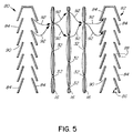
Figure 5 is a schematical side view of an alternative embodiment of an air inlet and an air outlet plenum suitable for use with the dryer ofFigure 1 ; -
Figure 6 is a schematical representation of a plate bank of another embodiment of a dryer for particulate material, the heat transfer plates being shown in end view; -
Figure 7 is a schematical representation of the plate banks and air plenums of another embodiment of a dryer, shown in plan view; and -
Figure 8 is a front view of the plate banks and air plenums of the dryer ofFigure 7 . - In the following description, certain specific details are set forth in order to provide a thorough understanding of various embodiments of the invention. However, one skilled in the art will understand that the invention may be practiced without these details. In other instances, well known structures associated with the technology have not been described in detail to avoid unnecessarily obscuring the descriptions of the embodiments of the invention.
- Unless the context requires otherwise, throughout the specification and claims which follow, the word "comprise" and variations thereof, such as "comprises" and "comprising" are to be construed in an open, inclusive sense, that is as "including but not limited to."
- Referring to the drawings,
reference numeral 10 generally indicates a dryer or evaporator comprising ahousing 12 which containsseveral banks 14 of one or more hollowheat transfer plates 16. In the present example, there are fourheat transfer plates 16 in eachplate bank 14. Theplates 16 in eachbank 14 are arranged in parallel spaced relationship for the flow ofparticulate material 18, which is to be dried, therebetween. The direction of flow of thematerial 18 is indicated byarrows 17 inFigure 3 . - Each
plate 16 has aninlet 20 for the introduction of a heating fluid, such as steam, and anoutlet 22, for discharging the cooled heating fluid, e.g. condensate if steam is used as heating fluid. For example, low pressure steam at about 110°C may be used as the heating fluid. - The
inlets 20 are connected to aheating fluid manifold 24, which in turn, during use, is connected to a source of heating fluid through opening (nozzle) 26. Theoutlets 22 are connected to a manifold 28 from which the spent heating fluid is discharged throughopening 30. If a heating liquid is used, such as hot water, the connections would be reversed, with the liquid entering throughopening 30 and exiting throughopening 26. - Each
plate 16 is provided with holes oropenings 32 therein, which are sealed around their peripheries, for the flow of purge air through theplates 16, as will be described below. To improve efficiency, theopenings 32 inadjacent plates 16 are offset with respect to each other, as more clearly shown inFigure 5 . - The
plate banks 14 are provided withair inlet plenums 34 for the provision of purge air andair outlet plenums 36 for exhausting the spent purge air. - The
air inlet plenums 34 are connected to apurge air manifold 38 which is connected to a source of air, throughopening 40, and theair outlet plenums 36 are connected to apurge air manifold 42 from which the purge air is exhausted throughopening 44. - The purge air inlet and
outlet plenums heat transfer plates 16. The air pervious sides can be of any suitable material which will allow the passage of purge air therethrough but at the same time counteract the entry of the material 18 being dried into theplenums - In the example illustrated in
Figures 1 ,3 and4 , the air-pervious sides are formed of wedge-wire screens for the passage of air therethrough. The screens are formed byelongate members 46, as shown inFigure 4 , which have triangular or V-shaped cross-sectional profiles and are arranged to form a smooth outside surface, i.e. the bases of the triangular profiles face outwardly. There is agap 48 of about 1 to 3 mm betweenadjacent members 46. The effect of this arrangement is that clogging of theplenums gap 48, larger particles are prevented from doing so and, due to the smooth outside profile, these particles can slide downwardly along the sides of theplenums - As shown in
FIGS. 1 and3 , theplenums plate banks 14. In this way,adjacent plate banks 14 share theinlet plenum 34 interposed between them andadjacent plate banks 14 share theoutlet plenum 36 interposed between them. - The
housing 12 forms ahopper 50 above theplate banks 14 and has aninlet 52 for introducing material to be dried into thehopper 50. Thehousing 12 has an outlet (not shown) on its underside for the outflow of dried material from thedryer 10. A mass flow device or discharge hopper (not shown) is provided at the outlet that creates mass flow or choked flow of the material being dried through the drier 10 and regulates the flow rate of the material. An example of such a mass flow device or discharge hopper is described inU.S. Pat. No. 5,167,274 . - The term "choked flow" in this specification means a flow other than a free fall of the individual particles under the force of gravity.
- During operation of the
dryer 10, the material to be dried, such as soybeans, flows downwardly from thehopper 50 in choked flow under the force of gravity between theheat transfer plates 16 while heating fluid is circulating through theplates 16. - In order to remove any gaseous emissions from the material being dried, such as water vapour in the case of soybeans, relatively dry air (purge air) is introduced into the
air inlet plenums 34 e.g. by means of a fan (not shown) via theinlet manifold 38. From theplenums 34 the purge air flows sideways through the wedge-wire screens of the plenums 34 (as shown byarrows 54 inFigure 3 ) in a direction across the direction of flow of the material being dried and through theopenings 32 in theplates 16, as shown by thearrows 56 inFigure 3 . - The drying of the
material 18 occurs as a result of the combination of the heat generated by the heating fluid circulating through theplates 16 and the dry air environment. In order to improve the efficiency of the process the purge air may be hot air. - The flow of the heating fluid through the
plates 16 is separate from the flow of purge air through theopenings 32 in theplates 16. This is as a result of theopenings 32 being sealed around their peripheries, as mentioned before. - The purge air is sucked into the
air outlet plenums 36, e.g. by an extractor fan (not shown) downstream of theair outlet manifold 42. During this flow of purge air through the material 18 being dried, gaseous emissions generated during the drying process are carried along with the purge air and are exhausted with the purge air. For example, in the case of soybeans, moist air will be exhausted from theplenums 36. - The bed depth through which the purge air must flow can be controlled by selecting an appropriate number of
plates 16 between the inlet andoutlet plenums plates 16 may depend on the nature of the material being dried (permeability of the bed). For example, for relatively coarse material the bed depth may be increased, whereas it may be decreased for less coarse material. In this way a manageable bed depth is achieved for the purge air. The requirement here is to achieve the necessary balance between air flow required to remove the moisture and available pressure drop from the fans. - It can be seen from the above that the invention provides a way to work with thin bed depths that will operate with pressure drops within the range of a radial flow fan, thereby alleviating the problems encountered in conventional methods of operation.
- The bed depth is the distance between an adjacent pair of
plenums line 58 inFigure 3 . As a guide, the bed depth may be selected to be from about 50 mm to about 1000 mm, e.g. for canola seeds the bed depth may be about 750 mm. - In
Figure 5 alternative plenums i.e.air inlet plenum 80 andair outlet plenum 82, are shown. - The
plenums plenums louvers 84. - The
louvers 84 are steeply inclined, e.g. at an angle of 70°, as shown at 86. This is a typical angle to maintain mass flow of the material being dried.Adjacent louvers 84 overlap, as shown at 88, but are spaced at about 20 mm so as to defineopenings 90 through which the air can enter or exit. - The
plenums plenum plates 16. - The air flow from the
inlet plenum 80 to theoutlet plenum 82 is shown by thelines 92. - In an alternative embodiment, the air inlet/
outlet plenums plates 16, as shown inFigure 6 . (InFigure 6 one plate bank of such analternative dryer 60 is shown with theplates 16 in end view.) - The air inlet/
outlet pipes pipes - The
air inlet pipes 62 are connected to a source of purge air for the flow of air into the pipes 62 (as indicated by arrows 66) and radially outwardly from thepipes 62 through the perforations (as indicated by the arrows 68). The air flow can be created in known fashion by the provision of one or more radial flow fans or extraction fans (not shown). - Likewise air flow is created through the
air outlet pipes 64 but in the opposite direction so as to draw spent purge air into thepipes 64 through the perforations (as indicated by the arrows 70) and to exit the pipes 64 (as indicated by the arrows 72). In this way, gaseous emissions from particulate material flowing downwardly between theplates 16, as indicated by thearrows 74, is removed by the purge air flow between thepipes pipes - In order to handle larger capacities, multiple banks of the
plates 16 can be stacked in series along the direction of flow of the material being dried. If desired, the plates may be offset between successive banks. - The dryer or evaporator according to the invention may also be used to remove volatiles from a bulk solid, e.g. the devolatization of plastic product which is contaminated with volatile solvents. For example, in the manufacture of plastic products, the plastic is formed into pellets. During the process, the pellets are purged with air or nitrogen to remove the volatile materials (solvents) on the surfaces of the pellets as well as from within the body of the material (pellets). This process is also referred to as "degassing". In such an application the
particulate material 18 referred to in the description of the process would be the pellets. - With reference to
Figure 7 and 8 reference numeral 100 generally indicates a dryer according to another embodiment. In the example shown, thedryer 100 comprises two banks ofheat transfer plates 102. Although theplates 102 are dimpled they do not have holes (such as theholes 32 of the plates 16). It will be appreciated that depending on requirements less or more than two banks ofplates 102 can be provided. - As in the case with the
plates 16, theplates 102 have inlets which are connected toheating manifolds 24 connected to a source of heating fluid and outlets which are connected to manifolds 28 from which the spent heating fluid is discharged. - A pair of
air inlet plenums 104 on the outside of the banks ofplates 102 is provided and inair outlet plenum 106 is provided between the banks ofplates 102. - The
air inlet plenums 104 have air pervious sides facing the banks ofplates 102 and theair outlet plenum 106 has a pair of opposed air pervious sides, each facing a bank ofplates 102. - The air pervious sides may be of any suitable type, such as for example the wedge wire tape shown in
Figure 4 or the angled louver type as shown inFigure 5 . - In the embodiment in
Figures 7 and 8 , theplates 102 are arranged at right angles with respect to theplenums air inlet plenums 104 between theplates 102 to theair outlet plenum 106 is shown by thearrows 108. - From the above it can be seen that in the
dryers - A further benefit of the present invention is that the purge air will be partially reheated as it passes through the thin layer of hot product (material 18) that is adjacent to each
plate holes 32 in theplate 16. Theholes 32 are offset between adjacent plates, as shown inFigure 5 , to improve the distribution of the purge air and improve the mechanism of the reheat. - The claims which follow are to be considered an integral part of the present disclosure. Although certain preferred embodiments of the present invention have been shown and described in detail, it should be understood that various changes and modifications may be made therein without departing from the scope of the appended claims. In general, in the following claims, the terms used should not be construed to limit the invention to the specific embodiments disclosed in the specification, but should be construed to include all methods and apparatuses that operate in accordance with the claims. Accordingly, the invention is not limited by the disclosure, but instead its scope is to be determined entirely by the following claims.
Claims (11)
- A dryer (10) for drying particulate material comprising a plurality of heat transfer plates (16) arranged in spaced relationship for the flow of the material to be dried therebetween, each heat transfer plate (16) being provided with an inlet (20) and an outlet (22) for the flow of a heating fluid through the plates (16) and a purge fluid delivery system arranged for providing a flow of purge fluid between the plates in a direction across the direction of flow of the material to be dried, wherein the purge fluid delivery system provides a flow path for the purge fluid which is isolated from the flow of the heating fluid through the plates, the purge fluid delivery system comprising at least one inlet plenum (34) characterised in that said purge fluid delivery system comprises at least one exhaust plenum (36) with the heat transfer plates (16) interposed between the at least one inlet plenum (34) and the at least one outlet plenum (36).
- The dryer of claim 1, wherein the flow of purge fluid extends through the heat transfer plates (16).
- The dryer of any one of claims 1 to 2, wherein each of the inlet and outlet plenums (34, 36) has an air pervious side facing the heat transfer plates (16).
- The dryer of claim 3, wherein said air pervious side is formed by spaced elongate members having substantially triangular cross-sectional profiles, each triangular profile having a substantially flat outwardly facing base portion.
- The dryer of claim 3, wherein said air pervious side is formed by a plurality of transverse louvers (84) inclined with respect to the horizontal direction, wherein air passages are defined between adjacent louvers.
- The dryer of claim 5, wherein the louvers (84) are inclined at an angle of about 70° with respect to the horizontal.
- The dryer of any one of claims 1 to 6, wherein the heat transfer plates (16) are arranged in banks (14) of plates, each bank (14) comprising one or more plates, the inlet and exhaust plenums (34, 36) interposed between the banks of plates.
- The dryer of claim 7, wherein at least some of said inlet and outlet plenums (34, 36) each has a pair of opposed air pervious sides.
- The dryer of any one of claims 1 to 8, wherein each of the heat transfer plates (16) has a heating fluid inlet (20) connected to a heating fluid manifold (24) for connection to a source of heating fluid and each of the heat transfer plates (16) has a heating fluid outlet (22) connected to an outlet manifold (28) for the discharge of spent heating fluid.
- The dryer of any one of claims 1 to 9, wherein each of the heat transfer plates (16) includes a plurality of holes (32) for the flow of purge fluid through the plates in the direction across the direction of flow of the material to be dried.
- A method of drying particulate material or removing volatiles from bulk solid material, comprising the steps of:introducing the material into flow passages defined between a plurality of spaced heat transfer plates (16);permitting the material to flow in choked flow under the force of gravity through the flow passages defined between the heat transfer plates (16);passing a heating fluid through the heat transfer plates (16), thereby to subject the material flowing through the flow passages to indirect heating; andsimultaneously causing a flow of a purge fluid in from an air inlet plenum (34), through the material being subjected to indirect heating in a direction across the flow of the material and out through an air outlet plenum (36), thereby to remove moisture or evaporated volatiles generated by the indirect heating of the material, the flow of the heating fluid through the heat transfer plates (16) being isolated from the flow of purge fluid.
Applications Claiming Priority (2)
| Application Number | Priority Date | Filing Date | Title |
|---|---|---|---|
| US11/418,055 US8578624B2 (en) | 2006-05-05 | 2006-05-05 | Indirect-heat thermal processing of particulate material |
| PCT/CA2007/000752 WO2007128104A1 (en) | 2006-05-05 | 2007-05-03 | Indirect-heat thermal processing of particulate material |
Publications (3)
| Publication Number | Publication Date |
|---|---|
| EP2032925A1 EP2032925A1 (en) | 2009-03-11 |
| EP2032925A4 EP2032925A4 (en) | 2014-05-21 |
| EP2032925B1 true EP2032925B1 (en) | 2016-04-06 |
Family
ID=38659908
Family Applications (1)
| Application Number | Title | Priority Date | Filing Date |
|---|---|---|---|
| EP07719677.2A Active EP2032925B1 (en) | 2006-05-05 | 2007-05-03 | Indirect-heat thermal processing of particulate material |
Country Status (10)
| Country | Link |
|---|---|
| US (1) | US8578624B2 (en) |
| EP (1) | EP2032925B1 (en) |
| AU (1) | AU2007247801B2 (en) |
| BR (1) | BRPI0711419B1 (en) |
| CA (1) | CA2650601C (en) |
| ES (1) | ES2579455T3 (en) |
| MX (1) | MX2008014195A (en) |
| RU (1) | RU2444687C2 (en) |
| UA (1) | UA95288C2 (en) |
| WO (1) | WO2007128104A1 (en) |
Families Citing this family (27)
| Publication number | Priority date | Publication date | Assignee | Title |
|---|---|---|---|---|
| US7987613B2 (en) * | 2004-10-12 | 2011-08-02 | Great River Energy | Control system for particulate material drying apparatus and process |
| US8579999B2 (en) | 2004-10-12 | 2013-11-12 | Great River Energy | Method of enhancing the quality of high-moisture materials using system heat sources |
| US7275644B2 (en) | 2004-10-12 | 2007-10-02 | Great River Energy | Apparatus and method of separating and concentrating organic and/or non-organic material |
| US8062410B2 (en) | 2004-10-12 | 2011-11-22 | Great River Energy | Apparatus and method of enhancing the quality of high-moisture materials and separating and concentrating organic and/or non-organic material contained therein |
| US8523963B2 (en) | 2004-10-12 | 2013-09-03 | Great River Energy | Apparatus for heat treatment of particulate materials |
| US9459054B2 (en) * | 2012-05-04 | 2016-10-04 | Solex Thermal Science Inc. | Heat exchanger for cooling bulk solids |
| US20140246184A1 (en) * | 2012-05-04 | 2014-09-04 | Solex Thermal Science Inc. | Heat exchanger for cooling or heating bulk solids |
| EP2953995A1 (en) | 2013-02-07 | 2015-12-16 | Covestro Deutschland AG | Method for the production of abs compositions having an improved surface following storage in a warm-humid environment |
| CN103398559B (en) * | 2013-07-11 | 2015-07-29 | 柳州化工股份有限公司 | A kind of method that moulded coal is dried |
| US9562194B2 (en) * | 2014-02-11 | 2017-02-07 | Solex Thermal Science Inc. | Torrefaction reactor |
| US9638478B2 (en) * | 2014-07-25 | 2017-05-02 | Solex Thermal Science Inc. | Heat exchanger for cooling bulk solids |
| EP2995898A3 (en) * | 2014-09-12 | 2016-05-11 | Solex Thermal Science Inc. | Heat exchanger for heating bulk solids |
| CN104296519A (en) * | 2014-10-14 | 2015-01-21 | 梁毅鸿 | Biomass fuel drying device |
| DE102015008094A1 (en) * | 2015-06-25 | 2016-12-29 | Universität Paderborn | Pillow plate heat exchangers |
| US9683781B2 (en) * | 2015-08-13 | 2017-06-20 | Solex Thermal Science Inc. | Indirect-heat thermal processing of bulk solids |
| RS61673B1 (en) | 2016-08-14 | 2021-04-29 | Dallmann Eng & Service | Heat exchanger modul for bulk material |
| MX2019008704A (en) | 2017-01-24 | 2020-01-14 | Crown Iron Works Co | Modular vertical seed conditioner heating section. |
| CN107576217B (en) * | 2017-10-11 | 2024-04-26 | 苏州协宏泰节能科技有限公司 | Screen plate type powder flow heat exchanger |
| CZ307802B6 (en) * | 2018-02-14 | 2019-05-15 | Farmet A.S. | Loose material heater |
| EP3663687B1 (en) * | 2018-12-05 | 2024-01-24 | ED-IPR ApS | An apparatus, a bottom plate component and a method for drying bulk particulate material |
| EP3999794A4 (en) * | 2019-07-19 | 2023-01-25 | Solex Thermal Science Inc. | HEAT TREATMENT OF BULK SOLIDS |
| US10982900B2 (en) | 2019-07-19 | 2021-04-20 | Solex Thermal Science Inc. | Thermal processing of bulk solids |
| CN113124674B (en) * | 2019-12-30 | 2024-06-21 | 四川奥凯川龙农产品干燥设备制造有限公司 | Shutter type wind material separation device |
| CN112050614A (en) * | 2020-09-29 | 2020-12-08 | 广州晟启能源设备有限公司 | Air source heat pump driving dividing wall type grain drying system |
| CN112066702A (en) * | 2020-09-29 | 2020-12-11 | 广州晟启能源设备有限公司 | Novel granule flows dividing wall heat conduction formula drying device |
| CN112050615A (en) * | 2020-09-29 | 2020-12-08 | 广州晟启能源设备有限公司 | Heat recovery type dehumidification heat pump driving dividing wall type drying system |
| EP4105479B1 (en) | 2021-06-15 | 2025-05-14 | John Cockerill Renewables S.A. | Particle heat exchanger for a solar tower power plant |
Family Cites Families (13)
| Publication number | Priority date | Publication date | Assignee | Title |
|---|---|---|---|---|
| US3397460A (en) * | 1965-10-12 | 1968-08-20 | Internat Processes Ltd | Heat exchange system for calciner |
| US4292743A (en) * | 1979-11-27 | 1981-10-06 | Razus Virgiliu T | Cereal dryer |
| US4424634A (en) * | 1981-06-19 | 1984-01-10 | Westelaken C | Modular column dryer for particulate material |
| DE3317204C1 (en) | 1982-05-08 | 1984-10-31 | Zippe Gmbh U. Co, 6980 Wertheim | Device for preheating glass fragments or similar loose materials |
| DE3507203C1 (en) * | 1985-03-01 | 1986-06-12 | DEC Engineering GmbH, 4650 Gelsenkirchen | Device for cleaning plate heat exchangers for the heat recovery of exhaust air |
| US5167274A (en) * | 1988-08-26 | 1992-12-01 | Cominco Ltd. | Method and apparatus for cooling particulate solids |
| SU1723424A1 (en) * | 1989-10-11 | 1992-03-30 | Сибирский Филиал Всесоюзного Научно-Производственного Объединения Элеваторной И Мукомольно-Крупяной Промышленности "Зернопродукт" | Air vent duct of cooling grain column |
| US5884416A (en) * | 1996-07-11 | 1999-03-23 | Crown Iron Works Company | Grain dryer module |
| US6328099B1 (en) * | 1999-04-21 | 2001-12-11 | Mississippi Chemical Corporation | Moving bed dryer |
| JP3865030B2 (en) | 1999-08-04 | 2007-01-10 | 金子農機株式会社 | Grain drying equipment |
| CA2451618A1 (en) * | 2001-06-25 | 2003-01-03 | Jott Australia Pty Ltd | Fluid/solid interaction apparatus |
| AUPR590101A0 (en) | 2001-06-25 | 2001-07-19 | Jott Australia Pty. Ltd. | Fluid/solid interaction apparatus |
| FI117214B (en) * | 2004-10-08 | 2006-07-31 | Eero Berg | Process and apparatus for drying solids or mixtures of materials |
-
2006
- 2006-05-05 US US11/418,055 patent/US8578624B2/en not_active Expired - Fee Related
-
2007
- 2007-05-03 UA UAA200813892A patent/UA95288C2/en unknown
- 2007-05-03 WO PCT/CA2007/000752 patent/WO2007128104A1/en not_active Ceased
- 2007-05-03 MX MX2008014195A patent/MX2008014195A/en active IP Right Grant
- 2007-05-03 BR BRPI0711419A patent/BRPI0711419B1/en not_active IP Right Cessation
- 2007-05-03 EP EP07719677.2A patent/EP2032925B1/en active Active
- 2007-05-03 CA CA2650601A patent/CA2650601C/en active Active
- 2007-05-03 ES ES07719677.2T patent/ES2579455T3/en active Active
- 2007-05-03 RU RU2008148016/06A patent/RU2444687C2/en active
- 2007-05-03 AU AU2007247801A patent/AU2007247801B2/en not_active Ceased
Also Published As
| Publication number | Publication date |
|---|---|
| AU2007247801B2 (en) | 2011-08-18 |
| WO2007128104A1 (en) | 2007-11-15 |
| EP2032925A4 (en) | 2014-05-21 |
| BRPI0711419B1 (en) | 2020-04-28 |
| US20070256316A1 (en) | 2007-11-08 |
| BRPI0711419A2 (en) | 2011-11-01 |
| UA95288C2 (en) | 2011-07-25 |
| RU2008148016A (en) | 2010-06-10 |
| ES2579455T3 (en) | 2016-08-11 |
| US8578624B2 (en) | 2013-11-12 |
| CA2650601A1 (en) | 2007-11-15 |
| EP2032925A1 (en) | 2009-03-11 |
| MX2008014195A (en) | 2009-03-31 |
| CA2650601C (en) | 2014-07-08 |
| RU2444687C2 (en) | 2012-03-10 |
| AU2007247801A1 (en) | 2007-11-15 |
Similar Documents
| Publication | Publication Date | Title |
|---|---|---|
| CA2650601C (en) | Indirect-heat thermal processing of particulate material | |
| CA1094313A (en) | Multiple stage grain dryer with intermediate steeping | |
| CA2964453C (en) | Mixed flow grain dryer with vacuum cool heat recovery system | |
| EP2647935A1 (en) | Grain drying arrangement and method for drying grain | |
| CN105492852B (en) | Drying method, drying equipment and drying system utilizing temperature difference | |
| US9995531B2 (en) | Multiple intermittence beehive grain dryer | |
| KR20210038890A (en) | Drying apparatus for wet matrices and relative drying method of wet matrices | |
| CN105473336A (en) | Variable humidity drying | |
| US1933960A (en) | Apparatus for the removal of vaporizable constituents from liquid or pasty or solid matters | |
| US20220106718A1 (en) | Drying device and drying method for a textile material web | |
| EP0060212B1 (en) | Tray drying chamber | |
| US1871773A (en) | Apparatus for drying seed-cotton | |
| US3591928A (en) | Continuous fluidization-type powder drying plant and method of use | |
| US10982900B2 (en) | Thermal processing of bulk solids | |
| EP4553433A1 (en) | Improved grain dryer | |
| KR20200130727A (en) | Nozzle box for drying equipment for drying plate-like materials | |
| NL1042123B1 (en) | Apparatus and method for drying a temperature-sensitive substance | |
| CN212101099U (en) | Urea finished product cooling device | |
| EP3999794A1 (en) | Thermal processing of bulk solids | |
| JP2007093028A (en) | Water removing apparatus for aggregate | |
| JP2024533210A (en) | Device | |
| US20090158610A1 (en) | Thermal coal upgrading processor | |
| KR20210086123A (en) | Device for drying wood chips | |
| WO2001086219A1 (en) | Method and apparatus for removing water from a product |
Legal Events
| Date | Code | Title | Description |
|---|---|---|---|
| PUAI | Public reference made under article 153(3) epc to a published international application that has entered the european phase |
Free format text: ORIGINAL CODE: 0009012 |
|
| 17P | Request for examination filed |
Effective date: 20081204 |
|
| AK | Designated contracting states |
Kind code of ref document: A1 Designated state(s): AT BE BG CH CY CZ DE DK EE ES FI FR GB GR HU IE IS IT LI LT LU LV MC MT NL PL PT RO SE SI SK TR |
|
| AX | Request for extension of the european patent |
Extension state: AL BA HR MK RS |
|
| A4 | Supplementary search report drawn up and despatched |
Effective date: 20140425 |
|
| RIC1 | Information provided on ipc code assigned before grant |
Ipc: F26B 17/12 20060101ALI20140417BHEP Ipc: F26B 17/16 20060101AFI20140417BHEP |
|
| 17Q | First examination report despatched |
Effective date: 20150423 |
|
| GRAP | Despatch of communication of intention to grant a patent |
Free format text: ORIGINAL CODE: EPIDOSNIGR1 |
|
| INTG | Intention to grant announced |
Effective date: 20151013 |
|
| RIN1 | Information on inventor provided before grant (corrected) |
Inventor name: HUANG, PETER XINGEUN Inventor name: JORDISON, NEVILLE Inventor name: ROZENDAAL, NIELS A. |
|
| GRAS | Grant fee paid |
Free format text: ORIGINAL CODE: EPIDOSNIGR3 |
|
| GRAA | (expected) grant |
Free format text: ORIGINAL CODE: 0009210 |
|
| AK | Designated contracting states |
Kind code of ref document: B1 Designated state(s): AT BE BG CH CY CZ DE DK EE ES FI FR GB GR HU IE IS IT LI LT LU LV MC MT NL PL PT RO SE SI SK TR |
|
| AX | Request for extension of the european patent |
Extension state: AL BA HR MK RS |
|
| REG | Reference to a national code |
Ref country code: GB Ref legal event code: FG4D |
|
| REG | Reference to a national code |
Ref country code: AT Ref legal event code: REF Ref document number: 788274 Country of ref document: AT Kind code of ref document: T Effective date: 20160415 Ref country code: CH Ref legal event code: EP |
|
| REG | Reference to a national code |
Ref country code: IE Ref legal event code: FG4D |
|
| REG | Reference to a national code |
Ref country code: PT Ref legal event code: SC4A Free format text: AVAILABILITY OF NATIONAL TRANSLATION Effective date: 20160509 |
|
| REG | Reference to a national code |
Ref country code: DE Ref legal event code: R096 Ref document number: 602007045645 Country of ref document: DE |
|
| REG | Reference to a national code |
Ref country code: FR Ref legal event code: PLFP Year of fee payment: 10 |
|
| REG | Reference to a national code |
Ref country code: NL Ref legal event code: FP |
|
| REG | Reference to a national code |
Ref country code: LT Ref legal event code: MG4D |
|
| REG | Reference to a national code |
Ref country code: ES Ref legal event code: FG2A Ref document number: 2579455 Country of ref document: ES Kind code of ref document: T3 Effective date: 20160811 |
|
| REG | Reference to a national code |
Ref country code: GR Ref legal event code: EP Ref document number: 20160401322 Country of ref document: GR Effective date: 20160729 |
|
| PG25 | Lapsed in a contracting state [announced via postgrant information from national office to epo] |
Ref country code: IS Free format text: LAPSE BECAUSE OF FAILURE TO SUBMIT A TRANSLATION OF THE DESCRIPTION OR TO PAY THE FEE WITHIN THE PRESCRIBED TIME-LIMIT Effective date: 20160806 Ref country code: FI Free format text: LAPSE BECAUSE OF FAILURE TO SUBMIT A TRANSLATION OF THE DESCRIPTION OR TO PAY THE FEE WITHIN THE PRESCRIBED TIME-LIMIT Effective date: 20160406 Ref country code: LT Free format text: LAPSE BECAUSE OF FAILURE TO SUBMIT A TRANSLATION OF THE DESCRIPTION OR TO PAY THE FEE WITHIN THE PRESCRIBED TIME-LIMIT Effective date: 20160406 Ref country code: PL Free format text: LAPSE BECAUSE OF FAILURE TO SUBMIT A TRANSLATION OF THE DESCRIPTION OR TO PAY THE FEE WITHIN THE PRESCRIBED TIME-LIMIT Effective date: 20160406 |
|
| PG25 | Lapsed in a contracting state [announced via postgrant information from national office to epo] |
Ref country code: LV Free format text: LAPSE BECAUSE OF FAILURE TO SUBMIT A TRANSLATION OF THE DESCRIPTION OR TO PAY THE FEE WITHIN THE PRESCRIBED TIME-LIMIT Effective date: 20160406 Ref country code: SE Free format text: LAPSE BECAUSE OF FAILURE TO SUBMIT A TRANSLATION OF THE DESCRIPTION OR TO PAY THE FEE WITHIN THE PRESCRIBED TIME-LIMIT Effective date: 20160406 |
|
| REG | Reference to a national code |
Ref country code: CH Ref legal event code: PL |
|
| REG | Reference to a national code |
Ref country code: DE Ref legal event code: R097 Ref document number: 602007045645 Country of ref document: DE |
|
| PG25 | Lapsed in a contracting state [announced via postgrant information from national office to epo] |
Ref country code: CH Free format text: LAPSE BECAUSE OF NON-PAYMENT OF DUE FEES Effective date: 20160531 Ref country code: DK Free format text: LAPSE BECAUSE OF FAILURE TO SUBMIT A TRANSLATION OF THE DESCRIPTION OR TO PAY THE FEE WITHIN THE PRESCRIBED TIME-LIMIT Effective date: 20160406 Ref country code: MC Free format text: LAPSE BECAUSE OF FAILURE TO SUBMIT A TRANSLATION OF THE DESCRIPTION OR TO PAY THE FEE WITHIN THE PRESCRIBED TIME-LIMIT Effective date: 20160406 Ref country code: EE Free format text: LAPSE BECAUSE OF FAILURE TO SUBMIT A TRANSLATION OF THE DESCRIPTION OR TO PAY THE FEE WITHIN THE PRESCRIBED TIME-LIMIT Effective date: 20160406 Ref country code: SK Free format text: LAPSE BECAUSE OF FAILURE TO SUBMIT A TRANSLATION OF THE DESCRIPTION OR TO PAY THE FEE WITHIN THE PRESCRIBED TIME-LIMIT Effective date: 20160406 Ref country code: CZ Free format text: LAPSE BECAUSE OF FAILURE TO SUBMIT A TRANSLATION OF THE DESCRIPTION OR TO PAY THE FEE WITHIN THE PRESCRIBED TIME-LIMIT Effective date: 20160406 Ref country code: LI Free format text: LAPSE BECAUSE OF NON-PAYMENT OF DUE FEES Effective date: 20160531 Ref country code: RO Free format text: LAPSE BECAUSE OF FAILURE TO SUBMIT A TRANSLATION OF THE DESCRIPTION OR TO PAY THE FEE WITHIN THE PRESCRIBED TIME-LIMIT Effective date: 20160406 |
|
| REG | Reference to a national code |
Ref country code: GR Ref legal event code: ML Ref document number: 20160401322 Country of ref document: GR Effective date: 20161207 |
|
| PLBE | No opposition filed within time limit |
Free format text: ORIGINAL CODE: 0009261 |
|
| STAA | Information on the status of an ep patent application or granted ep patent |
Free format text: STATUS: NO OPPOSITION FILED WITHIN TIME LIMIT |
|
| REG | Reference to a national code |
Ref country code: IE Ref legal event code: MM4A |
|
| PG25 | Lapsed in a contracting state [announced via postgrant information from national office to epo] |
Ref country code: GR Free format text: LAPSE BECAUSE OF NON-PAYMENT OF DUE FEES Effective date: 20161207 |
|
| 26N | No opposition filed |
Effective date: 20170110 |
|
| REG | Reference to a national code |
Ref country code: FR Ref legal event code: PLFP Year of fee payment: 11 |
|
| PG25 | Lapsed in a contracting state [announced via postgrant information from national office to epo] |
Ref country code: SI Free format text: LAPSE BECAUSE OF FAILURE TO SUBMIT A TRANSLATION OF THE DESCRIPTION OR TO PAY THE FEE WITHIN THE PRESCRIBED TIME-LIMIT Effective date: 20160406 Ref country code: IE Free format text: LAPSE BECAUSE OF NON-PAYMENT OF DUE FEES Effective date: 20160503 |
|
| REG | Reference to a national code |
Ref country code: FR Ref legal event code: PLFP Year of fee payment: 12 |
|
| PG25 | Lapsed in a contracting state [announced via postgrant information from national office to epo] |
Ref country code: CY Free format text: LAPSE BECAUSE OF FAILURE TO SUBMIT A TRANSLATION OF THE DESCRIPTION OR TO PAY THE FEE WITHIN THE PRESCRIBED TIME-LIMIT Effective date: 20160406 Ref country code: HU Free format text: LAPSE BECAUSE OF FAILURE TO SUBMIT A TRANSLATION OF THE DESCRIPTION OR TO PAY THE FEE WITHIN THE PRESCRIBED TIME-LIMIT; INVALID AB INITIO Effective date: 20070503 |
|
| PG25 | Lapsed in a contracting state [announced via postgrant information from national office to epo] |
Ref country code: LU Free format text: LAPSE BECAUSE OF NON-PAYMENT OF DUE FEES Effective date: 20160503 Ref country code: MT Free format text: LAPSE BECAUSE OF NON-PAYMENT OF DUE FEES Effective date: 20160531 Ref country code: TR Free format text: LAPSE BECAUSE OF FAILURE TO SUBMIT A TRANSLATION OF THE DESCRIPTION OR TO PAY THE FEE WITHIN THE PRESCRIBED TIME-LIMIT Effective date: 20160406 |
|
| PG25 | Lapsed in a contracting state [announced via postgrant information from national office to epo] |
Ref country code: BG Free format text: LAPSE BECAUSE OF FAILURE TO SUBMIT A TRANSLATION OF THE DESCRIPTION OR TO PAY THE FEE WITHIN THE PRESCRIBED TIME-LIMIT Effective date: 20160406 |
|
| REG | Reference to a national code |
Ref country code: AT Ref legal event code: UEP Ref document number: 788274 Country of ref document: AT Kind code of ref document: T Effective date: 20160406 |
|
| PGFP | Annual fee paid to national office [announced via postgrant information from national office to epo] |
Ref country code: NL Payment date: 20220512 Year of fee payment: 16 |
|
| PGFP | Annual fee paid to national office [announced via postgrant information from national office to epo] |
Ref country code: PT Payment date: 20220420 Year of fee payment: 16 Ref country code: IT Payment date: 20220509 Year of fee payment: 16 Ref country code: GB Payment date: 20220510 Year of fee payment: 16 Ref country code: FR Payment date: 20220511 Year of fee payment: 16 Ref country code: ES Payment date: 20220608 Year of fee payment: 16 Ref country code: DE Payment date: 20220510 Year of fee payment: 16 |
|
| PGFP | Annual fee paid to national office [announced via postgrant information from national office to epo] |
Ref country code: BE Payment date: 20220512 Year of fee payment: 16 Ref country code: AT Payment date: 20220506 Year of fee payment: 16 |
|
| P01 | Opt-out of the competence of the unified patent court (upc) registered |
Effective date: 20230529 |
|
| REG | Reference to a national code |
Ref country code: DE Ref legal event code: R119 Ref document number: 602007045645 Country of ref document: DE |
|
| REG | Reference to a national code |
Ref country code: NL Ref legal event code: MM Effective date: 20230601 |
|
| REG | Reference to a national code |
Ref country code: AT Ref legal event code: MM01 Ref document number: 788274 Country of ref document: AT Kind code of ref document: T Effective date: 20230503 |
|
| GBPC | Gb: european patent ceased through non-payment of renewal fee |
Effective date: 20230503 |
|
| REG | Reference to a national code |
Ref country code: BE Ref legal event code: MM Effective date: 20230531 |
|
| PG25 | Lapsed in a contracting state [announced via postgrant information from national office to epo] |
Ref country code: PT Free format text: LAPSE BECAUSE OF NON-PAYMENT OF DUE FEES Effective date: 20231103 Ref country code: AT Free format text: LAPSE BECAUSE OF NON-PAYMENT OF DUE FEES Effective date: 20230503 |
|
| PG25 | Lapsed in a contracting state [announced via postgrant information from national office to epo] |
Ref country code: NL Free format text: LAPSE BECAUSE OF NON-PAYMENT OF DUE FEES Effective date: 20230601 |
|
| PG25 | Lapsed in a contracting state [announced via postgrant information from national office to epo] |
Ref country code: IT Free format text: LAPSE BECAUSE OF NON-PAYMENT OF DUE FEES Effective date: 20230503 Ref country code: DE Free format text: LAPSE BECAUSE OF NON-PAYMENT OF DUE FEES Effective date: 20231201 Ref country code: GB Free format text: LAPSE BECAUSE OF NON-PAYMENT OF DUE FEES Effective date: 20230503 |
|
| PG25 | Lapsed in a contracting state [announced via postgrant information from national office to epo] |
Ref country code: FR Free format text: LAPSE BECAUSE OF NON-PAYMENT OF DUE FEES Effective date: 20230531 Ref country code: BE Free format text: LAPSE BECAUSE OF NON-PAYMENT OF DUE FEES Effective date: 20230531 |
|
| REG | Reference to a national code |
Ref country code: ES Ref legal event code: FD2A Effective date: 20240626 |
|
| PG25 | Lapsed in a contracting state [announced via postgrant information from national office to epo] |
Ref country code: ES Free format text: LAPSE BECAUSE OF NON-PAYMENT OF DUE FEES Effective date: 20230504 |
|
| PG25 | Lapsed in a contracting state [announced via postgrant information from national office to epo] |
Ref country code: ES Free format text: LAPSE BECAUSE OF NON-PAYMENT OF DUE FEES Effective date: 20230504 |