EP2031363A1 - Inertia and load torque estimating method and apparatus - Google Patents
Inertia and load torque estimating method and apparatus Download PDFInfo
- Publication number
- EP2031363A1 EP2031363A1 EP08163190A EP08163190A EP2031363A1 EP 2031363 A1 EP2031363 A1 EP 2031363A1 EP 08163190 A EP08163190 A EP 08163190A EP 08163190 A EP08163190 A EP 08163190A EP 2031363 A1 EP2031363 A1 EP 2031363A1
- Authority
- EP
- European Patent Office
- Prior art keywords
- signal
- generate
- estimate
- torque
- inertia
- Prior art date
- Legal status (The legal status is an assumption and is not a legal conclusion. Google has not performed a legal analysis and makes no representation as to the accuracy of the status listed.)
- Granted
Links
Images


Classifications
-
- G—PHYSICS
- G05—CONTROLLING; REGULATING
- G05B—CONTROL OR REGULATING SYSTEMS IN GENERAL; FUNCTIONAL ELEMENTS OF SUCH SYSTEMS; MONITORING OR TESTING ARRANGEMENTS FOR SUCH SYSTEMS OR ELEMENTS
- G05B19/00—Program-control systems
- G05B19/02—Program-control systems electric
- G05B19/18—Numerical control [NC], i.e. automatically operating machines, in particular machine tools, e.g. in a manufacturing environment, so as to execute positioning, movement or co-ordinated operations by means of program data in numerical form
- G05B19/416—Numerical control [NC], i.e. automatically operating machines, in particular machine tools, e.g. in a manufacturing environment, so as to execute positioning, movement or co-ordinated operations by means of program data in numerical form characterised by control of velocity, acceleration or deceleration
-
- G—PHYSICS
- G05—CONTROLLING; REGULATING
- G05B—CONTROL OR REGULATING SYSTEMS IN GENERAL; FUNCTIONAL ELEMENTS OF SUCH SYSTEMS; MONITORING OR TESTING ARRANGEMENTS FOR SUCH SYSTEMS OR ELEMENTS
- G05B2219/00—Program-control systems
- G05B2219/30—Nc systems
- G05B2219/41—Servomotor, servo controller till figures
- G05B2219/41123—Correction inertia of servo
-
- G—PHYSICS
- G05—CONTROLLING; REGULATING
- G05B—CONTROL OR REGULATING SYSTEMS IN GENERAL; FUNCTIONAL ELEMENTS OF SUCH SYSTEMS; MONITORING OR TESTING ARRANGEMENTS FOR SUCH SYSTEMS OR ELEMENTS
- G05B2219/00—Program-control systems
- G05B2219/30—Nc systems
- G05B2219/41—Servomotor, servo controller till figures
- G05B2219/41163—Adapt gain to friction, weight, inertia
-
- G—PHYSICS
- G05—CONTROLLING; REGULATING
- G05B—CONTROL OR REGULATING SYSTEMS IN GENERAL; FUNCTIONAL ELEMENTS OF SUCH SYSTEMS; MONITORING OR TESTING ARRANGEMENTS FOR SUCH SYSTEMS OR ELEMENTS
- G05B2219/00—Program-control systems
- G05B2219/30—Nc systems
- G05B2219/41—Servomotor, servo controller till figures
- G05B2219/41381—Torque disturbance observer to estimate inertia
Definitions
- the present invention relates to motor controllers and more specifically to methods and systems for identifying system inertia and load torque disturbances that are needed to properly tune motor controllers.
- motor/plant inertia identification is an important step in properly tuning a motor drive system.
- the way a motor and a linked load (i.e., the plant) respond to control signals (i.e., applied varying voltages) is directly related to motor/plant inertia and therefore, suitable control is directly related to plant inertia.
- One way to determine plant inertia has been to perform an inertia determining commissioning process prior to normal motor operation and then setting and assuming a constant system inertia value. While these processes work well, they have at least two primary shortcomings.
- commissioning processes take time to complete and therefore slow the process of setting up a control/drive system.
- a related issue is that, typically, a skilled engineer or technician is required to properly perform a commissioning procedure and therefore there are costs associated with each additional commissioning step required to set up a drive system.
- a position feedback signal and a derivable motor torque signal can be used to continually generate a system inertia estimate during normal drive operation and the inertia estimate can then be used to continually tune the drive system. Because the inertia estimate is generated during normal operation there is no need for a separate commissioning procedure. Because the inertia estimate is continually updated the estimate is always accurate and drive control is optimized.
- At least some inventive embodiments include a method for estimating a system inertia and a load torque in a motor controller, the method comprising the steps of providing an acceleration command signal, determining a motor position, using the motor position to generate an acceleration feedback signal, mathematically combining the acceleration feedback signal and a load torque signal to generate a system inertia estimate, mathematically combining the system inertia estimate and the acceleration command signal to generate a motor torque signal, mathematically combining the system inertia estimate and the acceleration feedback signal to generate an inertia torque and mathematically combining the inertia torque and the motor torque signal to generate the load torque estimate.
- the step of providing an acceleration command signal includes providing a velocity command signal, deriving a velocity feedback signal from the motor position and subtracting the motor velocity feedback signal from the velocity command signal.
- the step of mathematically combining the acceleration feedback signal and the load torque signal includes filtering the load torque signal to generate a load torque difference signal, multiplying the acceleration feedback signal and the load torque difference signal to generate an inertia product signal and integrating a derivative of the inertia product signal to generate the system inertia estimate.
- the step of mathematically combining the system inertia estimate and the acceleration command signal to generate a motor torque signal includes multiplying a derivative of the system inertia estimate and the acceleration command signal to generate a torque command signal and limiting the torque command signal to generate the motor torque signal.
- the step of multiplying a derivative of the system inertia estimate and the acceleration command signal includes low pass filtering the system inertia estimate to generate the derivative of the system inertia estimate.
- the step of mathematically combining the system inertia estimate and the acceleration feedback signal to generate an inertia torque includes multiplying the system inertia estimate by the acceleration feedback signal to generate the inertia torque.
- the step of mathematically combining the inertia torque and the motor torque signal to generate a load torque estimate includes subtracting the inertia torque from the motor torque signal to generate the load torque estimate.
- the step of using the load torque estimate to generate the load torque difference signal includes band pass filtering the load torque estimate.
- Other embodiments include a method for deriving a system inertia estimate and a load torque estimate in a motor controller, the method comprising the steps of providing a velocity command signal, sensing a motor position, using the motor position to generate a velocity feedback signal and an acceleration feedback signal, subtracting the velocity feedback signal from the velocity command signal to generate a velocity error signal, using the velocity error signal to generate an acceleration command signal, multiplying the acceleration feedback signal and a load torque difference signal to generate an inertia product signal, using the inertia product signal to generate the system inertia estimate, multiplying the system inertia estimate and the acceleration command signal to generate a motor torque signal, multiplying the acceleration feedback signal and the system inertia estimate to generate an inertia torque, subtracting the inertia torque from the motor torque signal to generate the load torque estimate and filtering the load torque estimate to generate the load torque difference signal.
- the step of using the inertia product signal to generate the system inertia estimate includes scaling the inertia product signal and integrating the scaled product signal to derive the system inertia estimate.
- the step of filtering the load torque estimate includes band pass filtering the load torque estimate.
- Still other embodiments include an apparatus for estimating a system inertia and a load torque in a motor controller, the apparatus comprising a processor programmed to perform the steps of providing an acceleration command signal, determining a motor position, using the motor position to generate an acceleration feedback signal, mathematically combining the acceleration feedback signal and a load torque signal to generate a system inertia estimate, mathematically combining the system inertia estimate and the acceleration command signal to generate a motor torque signal, mathematically combining the system inertia estimate and the acceleration feedback signal to generate an inertia torque and mathematically combining the inertia torque and the motor torque signal to generate the load torque estimate.
- the processor is programmed to perform the step of providing an acceleration command signal by providing a velocity command signal, deriving a velocity feedback signal from the motor position and subtracting the motor velocity feedback signal from the velocity command signal.
- the processor is programmed to perform the step of mathematically combining the acceleration feedback signal and the load torque signal by filtering the load torque signal to generate a load torque difference signal, multiplying the acceleration feedback signal and the load torque difference signal to generate an inertia product signal and integrating a derivative of the inertia product signal to generate the system inertia estimate.
- the processor is programmed to perform the step of mathematically combining the system inertia estimate and the acceleration command signal to generate a motor torque signal includes multiplying a derivative of the system inertia estimate and the acceleration command signal to generate a torque command signal and limiting the torque command signal to generate the motor torque signal.
- the processor is programmed to perform the step of multiplying a derivative of the system inertia estimate and the acceleration command signal by low pass filtering the system inertia estimate to generate the derivative of the system inertia estimate.
- the processor is programmed to perform the step of mathematically combining the system inertia estimate and the acceleration feedback signal to generate an inertia torque includes multiplying the system inertia estimate by the acceleration feedback signal to generate the inertia torque.
- the processor is programmed to perform the step of mathematically combining the inertia torque and the motor torque signal to generate a load torque estimate includes subtracting the inertia torque from the motor torque signal to generate the load torque estimate.
- the processor is programmed to perform the step of using the load torque estimate to generate the load torque difference signal includes band pass filtering the load torque estimate.
- Fig. 1 is a schematic diagram illustrating a drive/plant system that is consistent with at least some aspects of the present invention
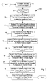
- Fig. 2 is a flow chart for estimating system inertia and a load torque that is consistent with at least some aspects of the present invention
- Fig. 3 is a graph illustrating actual and estimated system inertia as a function of time.
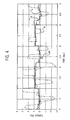
- Fig. 4 is a graph illustrating a motor torque, a load torque, a load torque estimate and a filtered load torque estimate derived using the inventive methods.
- a controller/plant system 10 that includes first, second and third summers 12, 26 and 32, respectively, a velocity regulator 14, first, second and third multipliers 16, 34 and 42, respectively, a torque/current limiter module 18, a delay module 20, a torque/current regulator 22, an inertia system 24, first, second and third low pass filters 28, 30 and 48, respectively, an integrator module 46, a analog to digital converter 36, a scaling module 44 and first and second derivative modules 38 and 40, respectively.
- inputs to system 10 include a velocity command signal ⁇ * and a load torque signal T L where command signal ⁇ * is provided by a system user the load torque signal T L is the torque applied to the system by a load (e.g., items resting on a conveyor belt, a roll of paper being unwound by a motor, etc.).
- a position sensing device is linked to inertia system 24 to sense position of a motor associated therewith and provide an analog position signal to converter 36.
- Converter 36 converts the analog position signal to a digital position feedback signal P f which is provided to first derivative module 38.
- First derivative module 38 takes the derivative of the position feedback signal P f and thereby generates a velocity feedback signal ⁇ f which is provided to derivative module 40.
- Second derivative module 40 take the derivative of the velocity feedback signal ⁇ f and thereby generates an acceleration feedback signal a f which is provided to both multipliers 42 and 34.
- Velocity feedback signal ⁇ f is provided to summer 12.
- Summer 12 subtracts the velocity feedback signal ⁇ f from the velocity command signal ⁇ * to generate a velocity error signal ⁇ e which is provided to velocity regulator 14.
- Velocity regulator 14 uses the velocity error signal ⁇ e to generate an acceleration command signal a * which is provided to multiplier 16.
- Multiplier 16 multiplies a filtered system inertia estimate l e and the acceleration command signal a * to generate a torque command signal T * which is provided to the torque/current limiter module 18.
- Limiter module 18 limits the torque command value T * to within a predefined range and provides the limited value to delay module 20. As the label implies, delay module 20 delays the limited value and generates a motor torque command signal T m * . .
- Motor torque command T m * is provided to the torque/current regulator 22 which regulates current applied to inertia system 24.
- System 24 includes a motor and load.
- multiplier 42 multiplies the acceleration feedback signal a f by a filtered load torque difference signal T L ⁇ to generate an inertia product signal.
- Scaler module 44 scales the inertia product signal and provides its output to integrator 46.
- Integrator 46 integrates the scaled inertia product signal to generate a system inertia estimate l est .
- System inertia estimate l est is provided to multiplier 34 and also to low pass filter 48.
- Low pass filter 48 filters out high frequency components of the system inertia estimate l est and provides the filtered inertia estimate to multiplier 16 which is used, along with the acceleration command signal a * to generate the torque command signal T * .
- the system inertia estimate l est is multiplied by the acceleration feedback signal a f to generate an inertia torque signal T l .
- Summer 26 subtracts the inertia torque signal T l from the motor torque command signal T m * to generate a load torque estimate T Lest .
- Load torque estimate T Lest is provided to low pass filter 28 which filters out high frequency components of the value estimate T Lest thereby generating a filtered load torque value T Lf1 .
- the filtered load torque value T Lf1 is provided to summer 32 and to low pass filter 30.
- filter 30 has a lower frequency set point than filter 28 and therefore filters out at least a portion of the signal passed by filter 28 corresponding to an upper range of frequencies passed by filter 28.
- the output of filter 30 is provided to summer 32.
- Summer 32 subtracts the output T Lf2 from filter 30 from the filtered load torque T Lf1 thereby generating the filtered load torque difference signal T L ⁇ which is provided to multiplier 42.
- a velocity command signal ⁇ * is provided.
- motor position is sensed and at block 56 the motor position is used to generate a velocity feedback signal and an acceleration feedback signal (see modules 38 and 40 in Fig. 1 ).
- the velocity feedback signal is subtracted from the velocity command signal to generate a velocity error signal (see summer 12 in Fig. 1 ).
- the velocity error signal is used to generate an acceleration command signal (see regulator 14 in Fig. 1 ).
- the acceleration feedback signal and the load torque difference signal are multiplied to generate an inertia product signal (see multiplier 42 in Fig. 1 ).
- the inertia product signal is scaled up and integrated to generate the inertia estimate signal l est (see 44 and 46 in Fig. 1 ).
- the system inertia estimate and the acceleration command signal are multiplied to generate a motor torque command signal T m * . .
- the acceleration feedback signal is multiplied by the system inertia estimate to generate inertia torque signal T l (see multiplier 34 in Fig. 1 ).
- the inertia torque signal is subtracted from the motor torque to generate a load torque estimate (see summer 26 in Fig. 1 ).
- the load torque estimate T Lest is filtered (see filter modules 28 and 30 in Fig. 1 ) to generate the load torque difference signal T L ⁇ .
- a graph is provided that includes a smooth sinusoidal system inertia value l actual and a stepped sinusoidal estimated inertia value l est derived using the inventive system.
- the inertia estimate generally tracks the actual system inertia.
- Fig. 4 includes waveforms corresponding to a motor torque T M , a load torque T L and load torque estimate T Lest and a filtered load torque estimate T Lf1 where it can be seen that the load torque estimate T Lest generally tracks the load torque T L and the filtered estimate even more closely follows the load torque T L .
- the inertia and load torque are calculated those values are used to modify drive control.
Landscapes
- Engineering & Computer Science (AREA)
- Human Computer Interaction (AREA)
- Manufacturing & Machinery (AREA)
- Physics & Mathematics (AREA)
- General Physics & Mathematics (AREA)
- Automation & Control Theory (AREA)
- Control Of Electric Motors In General (AREA)
Abstract
Description
- Not applicable.
- Not applicable.
- The present invention relates to motor controllers and more specifically to methods and systems for identifying system inertia and load torque disturbances that are needed to properly tune motor controllers.
- As well known in the motor control industry, motor/plant inertia identification is an important step in properly tuning a motor drive system. To this end, the way a motor and a linked load (i.e., the plant) respond to control signals (i.e., applied varying voltages) is directly related to motor/plant inertia and therefore, suitable control is directly related to plant inertia. One way to determine plant inertia has been to perform an inertia determining commissioning process prior to normal motor operation and then setting and assuming a constant system inertia value. While these processes work well, they have at least two primary shortcomings.
- First, commissioning processes take time to complete and therefore slow the process of setting up a control/drive system. A related issue is that, typically, a skilled engineer or technician is required to properly perform a commissioning procedure and therefore there are costs associated with each additional commissioning step required to set up a drive system.
- Second, in at least some applications system inertia changes during system operations. Where inertia changes during operation, the assumed constant value is erroneous and therefore drive control is less than optimal.
- One solution in the case of a system where inertia changes during operation is to routinely rerun the inertia estimating commissioning procedure (e.g., once a day). This solution, however, increases the time required to maintain an accurate estimate and does not work well where system inertia fluctuates during the interim periods between recalculation.
- It has been recognized that a position feedback signal and a derivable motor torque signal can be used to continually generate a system inertia estimate during normal drive operation and the inertia estimate can then be used to continually tune the drive system. Because the inertia estimate is generated during normal operation there is no need for a separate commissioning procedure. Because the inertia estimate is continually updated the estimate is always accurate and drive control is optimized.
- Consistent with the above, at least some inventive embodiments include a method for estimating a system inertia and a load torque in a motor controller, the method comprising the steps of providing an acceleration command signal, determining a motor position, using the motor position to generate an acceleration feedback signal, mathematically combining the acceleration feedback signal and a load torque signal to generate a system inertia estimate, mathematically combining the system inertia estimate and the acceleration command signal to generate a motor torque signal, mathematically combining the system inertia estimate and the acceleration feedback signal to generate an inertia torque and mathematically combining the inertia torque and the motor torque signal to generate the load torque estimate.
- In at least some cases the step of providing an acceleration command signal includes providing a velocity command signal, deriving a velocity feedback signal from the motor position and subtracting the motor velocity feedback signal from the velocity command signal. In some cases the step of mathematically combining the acceleration feedback signal and the load torque signal includes filtering the load torque signal to generate a load torque difference signal, multiplying the acceleration feedback signal and the load torque difference signal to generate an inertia product signal and integrating a derivative of the inertia product signal to generate the system inertia estimate.
- In some cases the step of mathematically combining the system inertia estimate and the acceleration command signal to generate a motor torque signal includes multiplying a derivative of the system inertia estimate and the acceleration command signal to generate a torque command signal and limiting the torque command signal to generate the motor torque signal. In some embodiments the step of multiplying a derivative of the system inertia estimate and the acceleration command signal includes low pass filtering the system inertia estimate to generate the derivative of the system inertia estimate.
- In other cases the step of mathematically combining the system inertia estimate and the acceleration feedback signal to generate an inertia torque includes multiplying the system inertia estimate by the acceleration feedback signal to generate the inertia torque. In some cases the step of mathematically combining the inertia torque and the motor torque signal to generate a load torque estimate includes subtracting the inertia torque from the motor torque signal to generate the load torque estimate. In some cases the step of using the load torque estimate to generate the load torque difference signal includes band pass filtering the load torque estimate.
- Other embodiments include a method for deriving a system inertia estimate and a load torque estimate in a motor controller, the method comprising the steps of providing a velocity command signal, sensing a motor position, using the motor position to generate a velocity feedback signal and an acceleration feedback signal, subtracting the velocity feedback signal from the velocity command signal to generate a velocity error signal, using the velocity error signal to generate an acceleration command signal, multiplying the acceleration feedback signal and a load torque difference signal to generate an inertia product signal, using the inertia product signal to generate the system inertia estimate, multiplying the system inertia estimate and the acceleration command signal to generate a motor torque signal, multiplying the acceleration feedback signal and the system inertia estimate to generate an inertia torque, subtracting the inertia torque from the motor torque signal to generate the load torque estimate and filtering the load torque estimate to generate the load torque difference signal.
- In some cases the step of using the inertia product signal to generate the system inertia estimate includes scaling the inertia product signal and integrating the scaled product signal to derive the system inertia estimate. In some case the step of filtering the load torque estimate includes band pass filtering the load torque estimate.
- Still other embodiments include an apparatus for estimating a system inertia and a load torque in a motor controller, the apparatus comprising a processor programmed to perform the steps of providing an acceleration command signal, determining a motor position, using the motor position to generate an acceleration feedback signal, mathematically combining the acceleration feedback signal and a load torque signal to generate a system inertia estimate, mathematically combining the system inertia estimate and the acceleration command signal to generate a motor torque signal, mathematically combining the system inertia estimate and the acceleration feedback signal to generate an inertia torque and mathematically combining the inertia torque and the motor torque signal to generate the load torque estimate.
- In some cases the processor is programmed to perform the step of providing an acceleration command signal by providing a velocity command signal, deriving a velocity feedback signal from the motor position and subtracting the motor velocity feedback signal from the velocity command signal. In some cases the processor is programmed to perform the step of mathematically combining the acceleration feedback signal and the load torque signal by filtering the load torque signal to generate a load torque difference signal, multiplying the acceleration feedback signal and the load torque difference signal to generate an inertia product signal and integrating a derivative of the inertia product signal to generate the system inertia estimate. In some cases the processor is programmed to perform the step of mathematically combining the system inertia estimate and the acceleration command signal to generate a motor torque signal includes multiplying a derivative of the system inertia estimate and the acceleration command signal to generate a torque command signal and limiting the torque command signal to generate the motor torque signal. In some cases the processor is programmed to perform the step of multiplying a derivative of the system inertia estimate and the acceleration command signal by low pass filtering the system inertia estimate to generate the derivative of the system inertia estimate.
- In some embodiments the processor is programmed to perform the step of mathematically combining the system inertia estimate and the acceleration feedback signal to generate an inertia torque includes multiplying the system inertia estimate by the acceleration feedback signal to generate the inertia torque. In some other cases the processor is programmed to perform the step of mathematically combining the inertia torque and the motor torque signal to generate a load torque estimate includes subtracting the inertia torque from the motor torque signal to generate the load torque estimate. In some cases the processor is programmed to perform the step of using the load torque estimate to generate the load torque difference signal includes band pass filtering the load torque estimate.
- To the accomplishment of the foregoing and related ends, the invention, then, comprises the features hereinafter fully described. The following description and the annexed drawings set forth in detail certain illustrative aspects of the invention. However, these aspects are indicative of but a few of the various ways in which the principles of the invention can be employed. Other aspects, advantages and novel features of the invention will become apparent from the following detailed description of the invention when considered in conjunction with the drawings.
-
Fig. 1 is a schematic diagram illustrating a drive/plant system that is consistent with at least some aspects of the present invention; -
Fig. 2 is a flow chart for estimating system inertia and a load torque that is consistent with at least some aspects of the present invention; -
Fig. 3 is a graph illustrating actual and estimated system inertia as a function of time; and -
Fig. 4 is a graph illustrating a motor torque, a load torque, a load torque estimate and a filtered load torque estimate derived using the inventive methods. - Referring now to the drawings wherein like reference numeral correspond to similar elements throughout the several views and, more specifically, referring to
Fig. 1 , the present invention will be described in the context of an exemplary controller/plant system 10 that includes first, second andthird summers velocity regulator 14, first, second andthird multipliers delay module 20, a torque/current regulator 22, aninertia system 24, first, second and thirdlow pass filters integrator module 46, a analog todigital converter 36, ascaling module 44 and first and secondderivative modules - Referring still to
Fig. 1 , inputs to system 10 include a velocity command signal ω* and a load torque signal TL where command signal ω* is provided by a system user the load torque signal TL is the torque applied to the system by a load (e.g., items resting on a conveyor belt, a roll of paper being unwound by a motor, etc.). A position sensing device is linked toinertia system 24 to sense position of a motor associated therewith and provide an analog position signal to converter 36. Converter 36, as the label implies, converts the analog position signal to a digital position feedback signal Pf which is provided to firstderivative module 38. - First
derivative module 38 takes the derivative of the position feedback signal Pf and thereby generates a velocity feedback signal ωf which is provided toderivative module 40. Secondderivative module 40 take the derivative of the velocity feedback signal ωf and thereby generates an acceleration feedback signal af which is provided to bothmultipliers - Velocity feedback signal ωf is provided to
summer 12.Summer 12 subtracts the velocity feedback signal ωf from the velocity command signal ω* to generate a velocity error signal ωe which is provided tovelocity regulator 14.Velocity regulator 14 uses the velocity error signal ωe to generate an acceleration command signal a* which is provided to multiplier 16. -
Multiplier 16 multiplies a filtered system inertia estimate le and the acceleration command signal a* to generate a torque command signal T* which is provided to the torque/current limiter module 18. Limiter module 18 limits the torque command value T* to within a predefined range and provides the limited value todelay module 20. As the label implies,delay module 20 delays the limited value and generates a motor torque command signal

inertia system 24.System 24 includes a motor and load. - Referring again to
Fig. 1 ,multiplier 42 multiplies the acceleration feedback signal af by a filtered load torque difference signal TLΔ to generate an inertia product signal. Scalermodule 44 scales the inertia product signal and provides its output tointegrator 46.Integrator 46 integrates the scaled inertia product signal to generate a system inertia estimate lest. System inertia estimate lest is provided tomultiplier 34 and also tolow pass filter 48. -
Low pass filter 48 filters out high frequency components of the system inertia estimate lest and provides the filtered inertia estimate tomultiplier 16 which is used, along with the acceleration command signal a* to generate the torque command signal T*. - At
multiplier 34 the system inertia estimate lest is multiplied by the acceleration feedback signal af to generate an inertia torque signal Tl. Summer 26 subtracts the inertia torque signal Tl from the motor torque command signal
low pass filter 28 which filters out high frequency components of the value estimate TLest thereby generating a filtered load torque value TLf1. The filtered load torque value TLf1 is provided tosummer 32 and to low pass filter 30. Here, filter 30 has a lower frequency set point thanfilter 28 and therefore filters out at least a portion of the signal passed byfilter 28 corresponding to an upper range of frequencies passed byfilter 28. The output of filter 30 is provided tosummer 32.Summer 32 subtracts the output TLf2 from filter 30 from the filtered load torque TLf1 thereby generating the filtered load torque difference signal TLΔ which is provided tomultiplier 42. - Referring to
Fig. 2 , anexemplary method 50 that is consistent with at least some aspects of the present invention is illustrated that may be performed by a processor programmed to perform the processes associated with the modules inFig. 1 described above. To this end, atprocess block 52, a velocity command signal ω* is provided. Atblock 54, motor position is sensed and atblock 56 the motor position is used to generate a velocity feedback signal and an acceleration feedback signal (seemodules Fig. 1 ). Atblock 58, the velocity feedback signal is subtracted from the velocity command signal to generate a velocity error signal (seesummer 12 inFig. 1 ). At block 60, the velocity error signal is used to generate an acceleration command signal (seeregulator 14 inFig. 1 ). Atblock 62, the acceleration feedback signal and the load torque difference signal are multiplied to generate an inertia product signal (seemultiplier 42 inFig. 1 ). Atblock 64, the inertia product signal is scaled up and integrated to generate the inertia estimate signal lest (see 44 and 46 inFig. 1 ). - Continuing, referring still to
Fig. 2 , at block 68, the system inertia estimate and the acceleration command signal are multiplied to generate a motor torque command signal
block 70 the acceleration feedback signal is multiplied by the system inertia estimate to generate inertia torque signal Tl (seemultiplier 34 inFig. 1 ). Atblock 72, the inertia torque signal is subtracted from the motor torque to generate a load torque estimate (seesummer 26 inFig. 1 ). Atblock 74, the load torque estimate TLest is filtered (seefilter modules 28 and 30 inFig. 1 ) to generate the load torque difference signal TLΔ. - Referring now to
Fig. 3 , a graph is provided that includes a smooth sinusoidal system inertia value lactual and a stepped sinusoidal estimated inertia value lest derived using the inventive system. As shown, the inertia estimate generally tracks the actual system inertia.Fig. 4 includes waveforms corresponding to a motor torque TM, a load torque TL and load torque estimate TLest and a filtered load torque estimate TLf1 where it can be seen that the load torque estimate TLest generally tracks the load torque TL and the filtered estimate even more closely follows the load torque TL. As the inertia and load torque are calculated those values are used to modify drive control. - One or more specific embodiments of the present invention have been described above. It should be appreciated that in the development of any such actual implementation, as in any engineering or design project, numerous implementation-specific decisions must be made to achieve the developers' specific goals, such as compliance with system-related and business related constraints, which may vary from one implementation to another. Moreover, it should be appreciated that such a development effort might be complex and time consuming, but would nevertheless be a routine undertaking of design, fabrication, and manufacture for those of ordinary skill having the benefit of this disclosure.
- Thus, the invention is to cover all modifications, equivalents, and alternatives falling within the spirit and scope of the invention as defined by the following appended claims.
- To apprise the public of the scope of this invention, the following claims are made:
Claims (19)
- A method for estimating a system inertia and a load torque in a motor controller, the method comprising the steps of:providing an acceleration command signal;determining a motor position;using the motor position to generate an acceleration feedback signal; mathematically combining the acceleration feedback signal and a load torque signal to generate a system inertia estimate;mathematically combining the system inertia estimate and the acceleration command signal to generate a motor torque signal;mathematically combining the system inertia estimate and the acceleration feedback signal to generate an inertia torque; andmathematically combining the inertia torque and the motor torque signal to generate the load torque estimate.
- The method of claim 1 wherein the step of providing an acceleration command signal includes providing a velocity command signal, deriving a velocity feedback signal from the motor position and subtracting the motor velocity feedback signal from the velocity command signal.
- The method of claim 1 wherein the step of mathematically combining the acceleration feedback signal and the load torque signal includes filtering the load torque signal to generate a load torque difference signal, multiplying the acceleration feedback signal and the load torque difference signal to generate an inertia product signal and integrating a derivative of the inertia product signal to generate the system inertia estimate.
- The method of claim 1 wherein the step of mathematically combining the system inertia estimate and the acceleration command signal to generate a motor torque signal includes multiplying a derivative of the system inertia estimate and the acceleration command signal to generate a torque command signal and limiting the torque command signal to generate the motor torque signal.
- The method of claim 4 wherein the step of multiplying a derivative of the system inertia estimate and the acceleration command signal includes low pass filtering the system inertia estimate to generate the derivative of the system inertia estimate.
- The method of claim 1 wherein the step of mathematically combining the system inertia estimate and the acceleration feedback signal to generate an inertia torque includes multiplying the system inertia estimate by the acceleration feedback signal to generate the inertia torque.
- The method of claim 1 wherein the step of mathematically combining the inertia torque and the motor torque signal to generate a load torque estimate includes subtracting the inertia torque from the motor torque signal to generate the load torque estimate.
- The method of claim 1 wherein the step of using the load torque estimate to generate the load torque difference signal includes band pass filtering the load torque estimate.
- A method for deriving a system inertia estimate and a load torque estimate in a motor controller, the method comprising the steps of:providing a velocity command signal;sensing a motor position;using the motor position to generate a velocity feedback signal and an acceleration feedback signal;subtracting the velocity feedback signal from the velocity command signal to generate a velocity error signal;using the velocity error signal to generate an acceleration command signal; multiplying the acceleration feedback signal and a load torque difference signal to generate an inertia product signal;using the inertia product signal to generate the system inertia estimate; multiplying the system inertia estimate and the acceleration command signal to generate a motor torque signal;multiplying the acceleration feedback signal and the system inertia estimate to generate an inertia torque;subtracting the inertia torque from the motor torque signal to generate the load torque estimate; andfiltering the load torque estimate to generate the load torque difference signal.
- The method of claim 9 wherein the step of using the inertia product signal to generate the system inertia estimate includes scaling the inertia product signal and integrating the scaled product signal to derive the system inertia estimate.
- The method of claim 9 wherein the step of filtering the load torque estimate includes band pass filtering the load torque estimate.
- An apparatus for estimating a system inertia and a load torque in a motor controller, the apparatus comprising:a processor programmed to perform the steps of:providing an acceleration command signal;determining a motor position;using the motor position to generate an acceleration feedback signal; mathematically combining the acceleration feedback signal and a load torque signal to generate a system inertia estimate;mathematically combining the system inertia estimate and the acceleration command signal to generate a motor torque signal;mathematically combining the system inertia estimate and the acceleration feedback signal to generate an inertia torque; andmathematically combining the inertia torque and the motor torque signal to generate the load torque estimate.
- The apparatus of claim 12 wherein the processor is programmed to perform the step of providing an acceleration command signal by providing a velocity command signal, deriving a velocity feedback signal from the motor position and subtracting the motor velocity feedback signal from the velocity command signal.
- The apparatus of claim 12 wherein the processor is programmed to perform the step of mathematically combining the acceleration feedback signal and the load torque signal by filtering the load torque signal to generate a load torque difference signal, multiplying the acceleration feedback signal and the load torque difference signal to generate an inertia product signal and integrating a derivative of the inertia product signal to generate the system inertia estimate.
- The apparatus of claim 12 wherein the processor is programmed to perform the step of mathematically combining the system inertia estimate and the acceleration command signal to generate a motor torque signal includes multiplying a derivative of the system inertia estimate and the acceleration command signal to generate a torque command signal and limiting the torque command signal to generate the motor torque signal.
- The apparatus of claim 15 wherein the processor is programmed to perform the step of multiplying a derivative of the system inertia estimate and the acceleration command signal by low pass filtering the system inertia estimate to generate the derivative of the system inertia estimate.
- The apparatus of claim 12 wherein the processor is programmed to perform the step of mathematically combining the system inertia estimate and the acceleration feedback signal to generate an inertia torque includes multiplying the system inertia estimate by the acceleration feedback signal to generate the inertia torque.
- The apparatus of claim 12 wherein the processor is programmed to perform the step of mathematically combining the inertia torque and the motor torque signal to generate a load torque estimate includes subtracting the inertia torque from the motor torque signal to generate the load torque estimate.
- The apparatus of claim 12 wherein the processor is programmed to perform the step of using the load torque estimate to generate the load torque difference signal includes band pass filtering the load torque estimate.
Applications Claiming Priority (1)
| Application Number | Priority Date | Filing Date | Title |
|---|---|---|---|
| US11/846,159 US7627440B2 (en) | 2007-08-28 | 2007-08-28 | Inertia and load torque estimating method and apparatus |
Publications (2)
| Publication Number | Publication Date |
|---|---|
| EP2031363A1 true EP2031363A1 (en) | 2009-03-04 |
| EP2031363B1 EP2031363B1 (en) | 2010-10-06 |
Family
ID=39941878
Family Applications (1)
| Application Number | Title | Priority Date | Filing Date |
|---|---|---|---|
| EP08163190A Ceased EP2031363B1 (en) | 2007-08-28 | 2008-08-28 | Inertia and load torque estimating method and apparatus |
Country Status (3)
| Country | Link |
|---|---|
| US (1) | US7627440B2 (en) |
| EP (1) | EP2031363B1 (en) |
| DE (1) | DE602008002871D1 (en) |
Cited By (5)
| Publication number | Priority date | Publication date | Assignee | Title |
|---|---|---|---|---|
| CN102445920A (en) * | 2010-09-07 | 2012-05-09 | 罗伯特·博世有限公司 | Collision detection method for a drive unit |
| WO2012164238A3 (en) * | 2011-05-27 | 2013-08-22 | Technelec Ltd | Method and apparatus for torque control of an electrical machine |
| CN104596702A (en) * | 2014-12-23 | 2015-05-06 | 北京首钢股份有限公司 | Measurement method for inherent rotational inertia |
| CN107607261A (en) * | 2017-09-19 | 2018-01-19 | 广西电网有限责任公司电力科学研究院 | A kind of method for obtaining electric generating set rotor rotary inertia |
| EP4109738A1 (en) * | 2021-06-21 | 2022-12-28 | Rockwell Automation Technologies, Inc. | System and method of trajectory shaping for feasible motion commands |
Families Citing this family (7)
| Publication number | Priority date | Publication date | Assignee | Title |
|---|---|---|---|---|
| JP4565034B2 (en) * | 2008-12-16 | 2010-10-20 | ファナック株式会社 | Control device and control system for inertia estimation |
| PL2335938T3 (en) | 2009-12-18 | 2013-07-31 | Agfa Gevaert | Laser markable security film |
| ES2400741T3 (en) | 2009-12-18 | 2013-04-11 | Agfa-Gevaert | Laser Marking Safety Film |
| EP3084951B1 (en) * | 2013-12-17 | 2020-12-02 | Corindus, Inc. | System for controlling a motor in a catheter procedure system |
| US11525728B1 (en) | 2021-11-16 | 2022-12-13 | Geotab Inc. | Systems and methods for determining an estimated weight of a vehicle |
| US12291215B2 (en) | 2021-11-16 | 2025-05-06 | Geotab Inc. | Systems and methods for determining an estimated weight of a vehicle |
| US12036998B2 (en) | 2022-10-04 | 2024-07-16 | Geotab Inc. | Systems and methods for determining an estimated weight of a vehicle |
Citations (3)
| Publication number | Priority date | Publication date | Assignee | Title |
|---|---|---|---|---|
| JPH0937416A (en) | 1995-07-19 | 1997-02-07 | Suzuki Motor Corp | Drive motor control device for electric vehicles |
| JP2004110190A (en) * | 2002-09-13 | 2004-04-08 | Yaskawa Electric Corp | Servo constant auto-tuning device |
| US20070143040A1 (en) | 2005-12-02 | 2007-06-21 | Sanyo Denki Co., Ltd. | Method of estimating load inertia for a motor |
Family Cites Families (14)
| Publication number | Priority date | Publication date | Assignee | Title |
|---|---|---|---|---|
| JPH06339292A (en) | 1993-04-02 | 1994-12-06 | Fanuc Ltd | Force controlling method by estimation of disturbance load |
| JP2569152B2 (en) | 1988-10-17 | 1997-01-08 | ファナック株式会社 | Servo control method |
| JP2745850B2 (en) | 1991-03-29 | 1998-04-28 | 三菱電機株式会社 | Numerical control device, numerical control system, method for automatically adjusting control parameters, method for changing feature amount criterion, and method for comprehensively determining a plurality of adjustment conditions |
| JPH06245561A (en) * | 1993-02-10 | 1994-09-02 | Fanuc Ltd | Abnormal load detection control method for servo motor |
| US5495158A (en) | 1994-09-30 | 1996-02-27 | Allen-Bradley Company, Inc. | Apparatus and method used with AC motors for controlling motor operation |
| JP3655378B2 (en) | 1995-11-28 | 2005-06-02 | ファナック株式会社 | Servo motor disturbance load estimation method |
| JP3185857B2 (en) | 1996-12-20 | 2001-07-11 | 株式会社安川電機 | Motor control device |
| JP3351990B2 (en) * | 1997-05-27 | 2002-12-03 | オークマ株式会社 | Ball screw drive system position controller |
| JP3731060B2 (en) | 2000-11-14 | 2006-01-05 | 株式会社日立製作所 | Inertia calculation method and motor drive device |
| DE10236847A1 (en) | 2002-08-08 | 2004-02-26 | Dr. Johannes Heidenhain Gmbh | Method for determining the moment of inertia of an electromotive drive system |
| TW591883B (en) | 2003-01-24 | 2004-06-11 | Delta Electronics Inc | Method of instant estimation of rotor inertia of a load motor |
| US6920800B2 (en) | 2003-08-15 | 2005-07-26 | Rockwell Automation Technologies, Inc. | Method for determining inertia of an electric motor and load |
| US7027961B2 (en) | 2004-05-18 | 2006-04-11 | Woodward Governor Company | Inertia identification for electric actuators with observer based controls |
| TWI302233B (en) | 2005-08-19 | 2008-10-21 | Delta Electronics Inc | Method for estimating load inertia and a system for controlling motor speed by using inverse model |
-
2007
- 2007-08-28 US US11/846,159 patent/US7627440B2/en active Active
-
2008
- 2008-08-28 EP EP08163190A patent/EP2031363B1/en not_active Ceased
- 2008-08-28 DE DE602008002871T patent/DE602008002871D1/en active Active
Patent Citations (3)
| Publication number | Priority date | Publication date | Assignee | Title |
|---|---|---|---|---|
| JPH0937416A (en) | 1995-07-19 | 1997-02-07 | Suzuki Motor Corp | Drive motor control device for electric vehicles |
| JP2004110190A (en) * | 2002-09-13 | 2004-04-08 | Yaskawa Electric Corp | Servo constant auto-tuning device |
| US20070143040A1 (en) | 2005-12-02 | 2007-06-21 | Sanyo Denki Co., Ltd. | Method of estimating load inertia for a motor |
Cited By (7)
| Publication number | Priority date | Publication date | Assignee | Title |
|---|---|---|---|---|
| CN102445920A (en) * | 2010-09-07 | 2012-05-09 | 罗伯特·博世有限公司 | Collision detection method for a drive unit |
| CN102445920B (en) * | 2010-09-07 | 2017-01-18 | 罗伯特·博世有限公司 | Collision detection method for a drive unit |
| WO2012164238A3 (en) * | 2011-05-27 | 2013-08-22 | Technelec Ltd | Method and apparatus for torque control of an electrical machine |
| CN104596702A (en) * | 2014-12-23 | 2015-05-06 | 北京首钢股份有限公司 | Measurement method for inherent rotational inertia |
| CN107607261A (en) * | 2017-09-19 | 2018-01-19 | 广西电网有限责任公司电力科学研究院 | A kind of method for obtaining electric generating set rotor rotary inertia |
| EP4109738A1 (en) * | 2021-06-21 | 2022-12-28 | Rockwell Automation Technologies, Inc. | System and method of trajectory shaping for feasible motion commands |
| US11716047B2 (en) | 2021-06-21 | 2023-08-01 | Rockwell Automation Technologies, Inc. | System and method for trajectory shaping for feasible motion commands |
Also Published As
| Publication number | Publication date |
|---|---|
| EP2031363B1 (en) | 2010-10-06 |
| US7627440B2 (en) | 2009-12-01 |
| DE602008002871D1 (en) | 2010-11-18 |
| US20090063058A1 (en) | 2009-03-05 |
Similar Documents
| Publication | Publication Date | Title |
|---|---|---|
| US7627440B2 (en) | Inertia and load torque estimating method and apparatus | |
| US7345443B2 (en) | Motor control apparatus | |
| US9285785B2 (en) | Motor control device for suppressing natural vibrations | |
| US6903529B2 (en) | Method and apparatus for damping mechanical oscillations of a shaft in machine tools, manufacturing machines and robots | |
| US9634600B2 (en) | Drive performance measurement | |
| EP1132790A1 (en) | Controller for machine | |
| JP3892823B2 (en) | Motor speed control device | |
| EP1560325B1 (en) | Position controller of motor | |
| US10558176B2 (en) | Feedback control system with periodic disturbance suppression and resonance/disturbance suppression using μ-synthesis | |
| CN1307782C (en) | Control constant adjusting apparatus | |
| US7187142B2 (en) | Motor drive with velocity noise filter | |
| US7109670B1 (en) | Motor drive with velocity-second compensation | |
| US7183738B2 (en) | Motor control device | |
| CA2344645A1 (en) | Method and device for determining the torque of an induction machine | |
| US7057366B1 (en) | Method for estimating load inertia and a system for controlling motor speed using inverse model | |
| US6274995B1 (en) | Method and circuit arrangement for automatically parameterizing a quick-acting digital speed control loop | |
| US7148635B1 (en) | Motor drive with synchronized timing | |
| RU2565490C1 (en) | Adaptive compensation method of influence of harmonic oscillations of moment of load in electromechanical system, and device for its implementation | |
| RU2576594C1 (en) | Method for automatic compensation of influence of harmonic oscillations of load moment in electromechanical system and device for its implementation | |
| JP5407435B2 (en) | Motor control device | |
| EP4492673A1 (en) | Motor control device, and automatic adjustment method for same | |
| RU2650341C1 (en) | Device for elimination of influence of harmonic perturbations of load moment in electromechanical system | |
| RU2761780C1 (en) | Method for adaptive control of an electromechanical system with a harmonic load moment in a wide range of speeds and apparatus for implementation thereof | |
| JP2004192448A (en) | Startup method of motor controller and motor controller with adjustment support function | |
| US20050261867A1 (en) | Inertia identification for electric actuators with observer based controls |
Legal Events
| Date | Code | Title | Description |
|---|---|---|---|
| PUAI | Public reference made under article 153(3) epc to a published international application that has entered the european phase |
Free format text: ORIGINAL CODE: 0009012 |
|
| AK | Designated contracting states |
Kind code of ref document: A1 Designated state(s): AT BE BG CH CY CZ DE DK EE ES FI FR GB GR HR HU IE IS IT LI LT LU LV MC MT NL NO PL PT RO SE SI SK TR |
|
| AX | Request for extension of the european patent |
Extension state: AL BA MK RS |
|
| 17Q | First examination report despatched |
Effective date: 20091002 |
|
| 17P | Request for examination filed |
Effective date: 20090824 |
|
| AKX | Designation fees paid |
Designated state(s): DE FR GB |
|
| GRAP | Despatch of communication of intention to grant a patent |
Free format text: ORIGINAL CODE: EPIDOSNIGR1 |
|
| GRAS | Grant fee paid |
Free format text: ORIGINAL CODE: EPIDOSNIGR3 |
|
| GRAA | (expected) grant |
Free format text: ORIGINAL CODE: 0009210 |
|
| AK | Designated contracting states |
Kind code of ref document: B1 Designated state(s): DE FR GB |
|
| REG | Reference to a national code |
Ref country code: GB Ref legal event code: FG4D |
|
| REF | Corresponds to: |
Ref document number: 602008002871 Country of ref document: DE Date of ref document: 20101118 Kind code of ref document: P |
|
| PLBE | No opposition filed within time limit |
Free format text: ORIGINAL CODE: 0009261 |
|
| STAA | Information on the status of an ep patent application or granted ep patent |
Free format text: STATUS: NO OPPOSITION FILED WITHIN TIME LIMIT |
|
| 26N | No opposition filed |
Effective date: 20110707 |
|
| REG | Reference to a national code |
Ref country code: DE Ref legal event code: R097 Ref document number: 602008002871 Country of ref document: DE Effective date: 20110707 |
|
| REG | Reference to a national code |
Ref country code: FR Ref legal event code: PLFP Year of fee payment: 8 |
|
| REG | Reference to a national code |
Ref country code: FR Ref legal event code: PLFP Year of fee payment: 9 |
|
| REG | Reference to a national code |
Ref country code: FR Ref legal event code: PLFP Year of fee payment: 10 |
|
| REG | Reference to a national code |
Ref country code: FR Ref legal event code: PLFP Year of fee payment: 11 |
|
| P01 | Opt-out of the competence of the unified patent court (upc) registered |
Effective date: 20230404 |
|
| PGFP | Annual fee paid to national office [announced via postgrant information from national office to epo] |
Ref country code: GB Payment date: 20230720 Year of fee payment: 16 |
|
| PGFP | Annual fee paid to national office [announced via postgrant information from national office to epo] |
Ref country code: FR Payment date: 20230720 Year of fee payment: 16 Ref country code: DE Payment date: 20230720 Year of fee payment: 16 |
|
| REG | Reference to a national code |
Ref country code: DE Ref legal event code: R119 Ref document number: 602008002871 Country of ref document: DE |
|
| GBPC | Gb: european patent ceased through non-payment of renewal fee |
Effective date: 20240828 |
|
| PG25 | Lapsed in a contracting state [announced via postgrant information from national office to epo] |
Ref country code: DE Free format text: LAPSE BECAUSE OF NON-PAYMENT OF DUE FEES Effective date: 20250301 |
|
| PG25 | Lapsed in a contracting state [announced via postgrant information from national office to epo] |
Ref country code: GB Free format text: LAPSE BECAUSE OF NON-PAYMENT OF DUE FEES Effective date: 20240828 |
|
| PG25 | Lapsed in a contracting state [announced via postgrant information from national office to epo] |
Ref country code: FR Free format text: LAPSE BECAUSE OF NON-PAYMENT OF DUE FEES Effective date: 20240831 |