EP2031233A1 - Ventilation et pressurisation de composants dans une turbomachine au moyen d'un moteur Stirling - Google Patents
Ventilation et pressurisation de composants dans une turbomachine au moyen d'un moteur Stirling Download PDFInfo
- Publication number
- EP2031233A1 EP2031233A1 EP08161468A EP08161468A EP2031233A1 EP 2031233 A1 EP2031233 A1 EP 2031233A1 EP 08161468 A EP08161468 A EP 08161468A EP 08161468 A EP08161468 A EP 08161468A EP 2031233 A1 EP2031233 A1 EP 2031233A1
- Authority
- EP
- European Patent Office
- Prior art keywords
- turbomachine
- turbine
- engine
- compressor
- flow
- Prior art date
- Legal status (The legal status is an assumption and is not a legal conclusion. Google has not performed a legal analysis and makes no representation as to the accuracy of the status listed.)
- Granted
Links
Images

Classifications
-
- F—MECHANICAL ENGINEERING; LIGHTING; HEATING; WEAPONS; BLASTING
- F02—COMBUSTION ENGINES; HOT-GAS OR COMBUSTION-PRODUCT ENGINE PLANTS
- F02C—GAS-TURBINE PLANTS; AIR INTAKES FOR JET-PROPULSION PLANTS; CONTROLLING FUEL SUPPLY IN AIR-BREATHING JET-PROPULSION PLANTS
- F02C7/00—Features, components parts, details or accessories, not provided for in, or of interest apart form groups F02C1/00 - F02C6/00; Air intakes for jet-propulsion plants
- F02C7/32—Arrangement, mounting, or driving, of auxiliaries
-
- F—MECHANICAL ENGINEERING; LIGHTING; HEATING; WEAPONS; BLASTING
- F02—COMBUSTION ENGINES; HOT-GAS OR COMBUSTION-PRODUCT ENGINE PLANTS
- F02C—GAS-TURBINE PLANTS; AIR INTAKES FOR JET-PROPULSION PLANTS; CONTROLLING FUEL SUPPLY IN AIR-BREATHING JET-PROPULSION PLANTS
- F02C6/00—Plural gas-turbine plants; Combinations of gas-turbine plants with other apparatus; Adaptations of gas-turbine plants for special use
- F02C6/18—Plural gas-turbine plants; Combinations of gas-turbine plants with other apparatus; Adaptations of gas-turbine plants for special use using the waste heat of gas-turbine plants outside the plants themselves, e.g. gas-turbine power heat plants
-
- F—MECHANICAL ENGINEERING; LIGHTING; HEATING; WEAPONS; BLASTING
- F02—COMBUSTION ENGINES; HOT-GAS OR COMBUSTION-PRODUCT ENGINE PLANTS
- F02G—HOT GAS OR COMBUSTION-PRODUCT POSITIVE-DISPLACEMENT ENGINE PLANTS; USE OF WASTE HEAT OF COMBUSTION ENGINES; NOT OTHERWISE PROVIDED FOR
- F02G2254/00—Heat inputs
- F02G2254/15—Heat inputs by exhaust gas
-
- F—MECHANICAL ENGINEERING; LIGHTING; HEATING; WEAPONS; BLASTING
- F05—INDEXING SCHEMES RELATING TO ENGINES OR PUMPS IN VARIOUS SUBCLASSES OF CLASSES F01-F04
- F05D—INDEXING SCHEME FOR ASPECTS RELATING TO NON-POSITIVE-DISPLACEMENT MACHINES OR ENGINES, GAS-TURBINES OR JET-PROPULSION PLANTS
- F05D2260/00—Function
- F05D2260/84—Redundancy
-
- Y—GENERAL TAGGING OF NEW TECHNOLOGICAL DEVELOPMENTS; GENERAL TAGGING OF CROSS-SECTIONAL TECHNOLOGIES SPANNING OVER SEVERAL SECTIONS OF THE IPC; TECHNICAL SUBJECTS COVERED BY FORMER USPC CROSS-REFERENCE ART COLLECTIONS [XRACs] AND DIGESTS
- Y02—TECHNOLOGIES OR APPLICATIONS FOR MITIGATION OR ADAPTATION AGAINST CLIMATE CHANGE
- Y02E—REDUCTION OF GREENHOUSE GAS [GHG] EMISSIONS, RELATED TO ENERGY GENERATION, TRANSMISSION OR DISTRIBUTION
- Y02E20/00—Combustion technologies with mitigation potential
- Y02E20/30—Technologies for a more efficient combustion or heat usage
Definitions
- the present invention relates to turbofan engines, such as aircraft turbojets.
- a turbomachine it is common to take energy to allow the operation of organs of the turbomachine.
- Energy samples are for example provided for driving a fuel pump, the supply of actuators and computers, or for the pressurization of oil enclosures.
- additional withdrawals are usually provided, for example for the supply of electricity on board, the supply of actuators of the aircraft such as control surfaces or for the pressurization of the aircraft. cabin of the plane.
- These energy withdrawals consist mainly of air samples taken from the air flow circulating in the high-pressure compressor of the turbomachine, and from mechanical samples taken from the high-pressure rotor of this turbomachine.
- the object of the invention is in particular to provide a simple, economical and effective solution to this problem, making it possible to reduce the specific fuel consumption of turbomachines, and relates to a turbomachine equipped with a source of energy that makes it possible to avoid at least part of the aforementioned samples.
- a turbomachine with a double flow essentially comprising a blower, a compressor, a combustion chamber, a turbine and an exhaust casing, characterized in that it comprises an auxiliary air compressor driven by an engine.
- Stirling mounted downstream of the combustion chamber and having a hot chamber in thermal contact with the hot gas stream coming out of the turbine and a cold chamber in thermal contact with a flow of cold gas generated by the blower and flowing around the turbine and the exhaust casing.
- the Stirling cycle heat engine commonly called the “Stirling engine” makes it possible to take advantage of the difference in temperature between the flow of hot gases, or primary flow, leaving the turbine and the flow of cold gas, or secondary flow, generated by the blower, to produce mechanical energy.
- This type of engine is characterized by a very good efficiency of the order of 40%, by a very good reliability and a long life.
- the theoretical cycle of operation of such an engine comprises four successive phases: an isochoric heating phase followed by an isothermal expansion phase of the working fluid in the hot chamber, then an isochoric cooling phase followed by a compression phase Isothermal working fluid in the cold room.
- the mechanical energy produced by the Stirling engine is used to drive an auxiliary air compressor to supply pressurized air to components of the turbomachine, so as to reduce the need for air sampling on the engine. flow of air flowing in the high pressure compressor of this turbomachine.
- the Stirling engine is fixed on the turbine casing or on the exhaust casing, which allows to benefit from a large free space between the flow streams of the primary and secondary streams.
- secondary for housing Stirling engine and auxiliary compressor. This zone is all the more appropriate if the temperature difference between the primary flow of hot gases and the secondary flow of cold gases is approximately 450 degrees under normal operating conditions, which constitutes a thermal gradient sufficient to allow the Stirling engine to work properly.
- the Stirling engine comprises a heat exchanger housed in the cold gas flow and a heat exchanger housed in the hot gas stream, these exchangers preferably having internal and / or external fins.
- the output of the auxiliary air compressor is connected to means for venting or pressurizing a component of the turbomachine by a conduit equipped with a controlled valve or autonomous two-position , connecting the ventilation or pressurizing means of the component either at the output of the auxiliary compressor, or at means for withdrawing air from the compressor of the turbomachine.
- the turbomachine when the turbomachine operates at low speed, the thermal gradient between the hot gas and the cold gas is insufficient to allow proper operation of the Stirling engine, and cooling or pressurizing the component of the turbomachine is provided in a conventional manner by a sampling on the air flow of the compressor of the turbomachine. Only when the speed reaches a level sufficient to allow the Stirling engine to function properly, does the controlled valve switch to its position of connecting ventilation or pressurization means to the output of the auxiliary compressor.
- valve is controlled by an electronic control unit, for example from a measurement of the temperature of the gases passing through the turbine.
- valve is a self-contained valve calibrated to the pressure level required for ventilation and pressurization of the turbomachine.
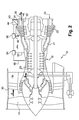
- the figure 1 represents a turbofan engine 10 and comprising a nacelle 12 in which a fan wheel 14 is mounted upstream of a motor body 16 essentially comprising, from upstream to downstream, a compressor 20, a combustion chamber 21, a turbine 22, an exhaust casing 24 and an exhaust cone 26.
- the fan wheel 14 is rotated by the turbine 22 of the turbojet, in a manner well known to those skilled in the art.
- the blower 14 generates a secondary air flow A, which flows backward around the turbojet in a blower line 18, and which provides a portion of the thrust of the engine.
- Part of the air entering the engine forms a primary flow B which feeds the inlet compressor 20 of the turbojet, then is mixed with fuel in the combustion chamber 21.
- the combustion gases leaving the combustion chamber cause the turbine 22 and are ejected between two coaxial walls 32, 34 of the exhaust casing 24 and exit the turbojet engine by flowing along the ejection cone 26.
- the fan duct 18 is formed of two substantially cylindrical coaxial walls, respectively internal 28 and outer 30.
- the inner wall 28 of the fan duct is generally called I.F.D. (Inner Fan Duct) while the outer wall 30 is generally called O.F.D. (Outer Fan Duct) and is surrounded by the nacelle 12.
- the two coaxial walls, respectively inner 32 and outer 34, of the exhaust casing 24 are connected by structural radial arms 36.
- Each radial arm 36 of the exhaust casing 24 connects the coaxial walls 32, 34 of this housing to the cylindrical walls 28, 30 of the fan duct 18, so that a portion 40 of the arm 36 intercepts the primary flow B while another part 42 of this arm intercepts the secondary flow A.
- the radial arm 36 visible in the upper half of the figure 1 includes a Birl Stirling cycle engine.
- This engine comprises, in a conventional manner, a hot chamber and a cold chamber which are connected for the circulation of a working fluid contained in these chambers and moved from one chamber to the other by the movement of a displacer piston.
- the hot chamber is disposed in the portion 40 of the arm 36 which intercepts the primary flow B of hot air, while the cold room is disposed in the portion 42 of the arm 36 which intercepts the secondary flow A of cold air.
- Fines 38 are advantageously formed on the outer and / or inner surface of the radial arms 36 at the portions 40 and 42 of these arms, in order to optimize the heat exchange between the flow B of hot air and the working fluid contained in the hot chamber housed in the portion 40 of the radial arm on the one hand, and between the cold air flow A and the working fluid contained in the cold chamber housed in the portion 42 of this arm.
- the working fluid During its circulation in the cold and hot rooms, the working fluid describes a Stirling thermodynamic cycle consisting of four successive phases during which it is in turn cooled, compressed, heated and then relaxed, driving a piston of job.
- the displacer and working pistons are housed in a working chamber connected to the hot and cold chambers, and disposed in a space 44 commonly called "interveine", between the flow veins of the primary flow B and secondary A is between the outer wall 34 of the exhaust casing and the inner wall 28 delimiting the fan duct, so that this working chamber is not in thermal contact with the primary and secondary flows.
- the working chamber could also be fixed on the radially inner face of the inner wall 32 of the exhaust casing, provided that the heat exchanges with the primary flow in contact with this wall 32 are limited by a thermal insulation means. .
- the working piston of the Stirling engine forms or drives a movable member of an auxiliary air compressor, housed in the intervein space 44, and intended to supply pressurized air components of the turbomachine to ensure, for example, their ventilation or their pressurization.
- FIG. 2 is schematically shown the connection of the air outlet of the auxiliary compressor 48 to the inlet 46 of a pressurized air distribution circuit (not visible) to the components of the turbomachine.
- Samples 50, 52 on the flow of air flowing in the high-pressure compressor 20 of the turbomachine are arranged to ensure the supply of the pressurized air distribution circuit during the operating phases of the turbojet engine where the difference the temperature between the cold gases of the secondary flow A and the hot gases of the primary flow B is too small to allow the Stirling engine 53 to provide sufficient mechanical power for the drive of the auxiliary compressor 48.
- a two-position valve 54 makes it possible to alternately connect the inlet of the air distribution circuit to the sample 50 on the fourth stage of the high-pressure compressor 20, during the start-up phases of the turbojet engine, and to the sample 52 on the ninth stage of the high-pressure compressor 20, in cruise mode as long as the thermal difference between the primary and secondary flows is not sufficient to allow the auxiliary compressor 48 to be driven by the Stirling engine or in the event of failure of the Stirling engine or the compressor auxiliary.
- a two-position valve 56 makes it possible to alternately connect the inlet of the air distribution circuit to the valve 54 when the turbojet engine is in one of the aforementioned operating situations, and to the auxiliary compressor 48 when the thermal difference between the primary and secondary flows reaches a threshold allowing the Stirling 53 engine to effectively drive the auxiliary compressor 48.
- valves 54 and 56 are controlled by an electronic control unit of the FADEC type, based on temperature measurements of the hot and cold gases flowing in the turbomachine, in the vicinity of the Stirling engine.
- valves could be controlled from measurements of the air pressure delivered by the samples 50, 52 and by the auxiliary compressor 48.
- valves could also be autonomous, and calibrated on the pressure levels necessary to supply the pressurized air distribution circuit.
- This air distribution circuit ensures for example the pressurization of turbomachine bearing housing covers, the ventilation of the first stage of a low pressure distributor, the ventilation of low pressure turbine disc rims, and the purge of a cavity located downstream of a high pressure turbine disk.
- the auxiliary compressor 48 delivers a flow rate of 1.5 kg / s of air at a relative pressure of the order of 0.3 bar in nominal operating mode.
- This compressor is in the form of a cylinder of about 100 mm in diameter for approximately 120 mm in length.
- This compressor requires that a mechanical power of about 10 kW is transmitted to it by the Stirling engine, this engine being roughly in the form of a cylinder of about 100 mm in diameter for approximately 200 mm in length.
- the invention therefore makes it possible to limit the use of withdrawals from the air stream that is useful for propulsion flowing in the turbojet engine compressor, thanks to an auxiliary compressor driven by a Stirling engine capable of converting air from the engine. thermal energy contained in the primary flow of hot gases from the combustion chamber of the turbojet mechanical energy.
- the invention is of course not limited to aircraft turbojets and can be applied to any type of turbofan engine.
Landscapes
- Engineering & Computer Science (AREA)
- Chemical & Material Sciences (AREA)
- Combustion & Propulsion (AREA)
- Mechanical Engineering (AREA)
- General Engineering & Computer Science (AREA)
- Structures Of Non-Positive Displacement Pumps (AREA)
- Supercharger (AREA)
Abstract
Description
- La présente invention concerne les turbomachines à double flux, telles que les turboréacteurs d'avion.
- Dans une turbomachine, il est courant de prélever de l'énergie pour permettre le fonctionnement d'organes de la turbomachine. Des prélèvements d'énergie sont par exemple prévus pour l'entraînement d'une pompe à carburant, l'alimentation d'actuateurs et de calculateurs, ou encore pour la pressurisation d'enceintes d'huile. Dans le cas d'un turboréacteur d'avion, des prélèvements supplémentaires sont habituellement prévus, par exemple pour la fourniture d'électricité à bord, l'alimentation d'actuateurs de l'avion tels que des gouvernes ou encore pour la pressurisation de la cabine de l'avion.
- Ces prélèvements d'énergie consistent principalement en des prélèvements d'air sur le flux d'air circulant dans le compresseur haute pression de la turbomachine, et en des prélèvements mécaniques sur le rotor haute pression de cette turbomachine.
- Or, ces prélèvements nécessitent un travail supplémentaire de la part du compresseur de la turbomachine, entraînant une augmentation de sa consommation spécifique de carburant.
- L'invention a notamment pour but d'apporter une solution simple, économique et efficace à ce problème, permettant de réduire la consommation spécifique de carburant des turbomachines, et a pour objet une turbomachine équipée d'une source d'énergie permettant d'éviter une partie au moins des prélèvements précités.
- Elle propose à cet effet une turbomachine à double flux, comprenant essentiellement une soufflante, un compresseur, une chambre de combustion, une turbine et un carter d'échappement, caractérisée en ce qu'elle comprend un compresseur d'air auxiliaire entraîné par un moteur Stirling monté en aval de la chambre de combustion et ayant une chambre chaude en contact thermique avec le flux de gaz chauds sortants de la turbine et une chambre froide en contact thermique avec un flux de gaz froids généré par la soufflante et s'écoulant autour de la turbine et du carter d'échappement.
- Le moteur thermique à cycle de Stirling, couramment appelé « moteur Stirling », permet de tirer parti de la différence de température entre le flux de gaz chauds, ou flux primaire, sortant de la turbine et le flux de gaz froids, ou flux secondaire, généré par la soufflante, pour produire de l'énergie mécanique. Ce type de moteur se caractérise par un très bon rendement de l'ordre de 40%, par une très bonne fiabilité et une grande longévité.
- Le cycle théorique de fonctionnement d'un tel moteur comprend quatre phases successives : une phase de chauffage isochore suivie d'une phase de détente isotherme du fluide de travail dans la chambre chaude, puis une phase de refroidissement isochore suivie d'une phase de compression isotherme du fluide de travail dans la chambre froide.
- L'énergie mécanique produite par le moteur Stirling sert à l'entraînement d'un compresseur à air auxiliaire destiné à fournir de l'air sous pression à des composants de la turbomachine, de manière à réduire les besoins en prélèvements d'air sur le flux d'air circulant dans le compresseur haute pression de cette turbomachine.
- Dans un mode de réalisation préféré de l'invention, le moteur Stirling est fixé sur le carter de turbine ou sur le carter d'échappement, ce qui permet de bénéficier d'un espace libre important entre les veines d'écoulement des flux primaire et secondaire pour le logement du moteur Stirling et du compresseur auxiliaire. Cette zone se révèle d'autant plus appropriée que l'écart de température entre le flux primaire de gaz chauds et le flux secondaire de gaz froids y est d'environ 450 degrés en régime de fonctionnement normal, ce qui constitue un gradient thermique suffisant pour permettre un bon fonctionnement du moteur Stirling.
- Selon une autre caractéristique de l'invention, le moteur Stirling comprend un échangeur de chaleur logé dans le flux de gaz froids et un échangeur de chaleur logé dans le flux de gaz chauds, ces échangeurs comportant de préférence des ailettes internes et/ou externes.
- Ces échangeurs permettent de maximiser les échanges de chaleur entre le flux de gaz froids, respectivement de gaz chauds, et un fluide de travail contenu dans le moteur Stirling, pour optimiser les performances de ce dernier.
- Dans le mode de réalisation préféré de l'invention, la sortie du compresseur d'air auxiliaire est reliée à des moyens de ventilation ou de pressurisation d'un composant de la turbomachine par un conduit équipé d'une vanne commandée ou autonome à deux positions, connectant les moyens de ventilation ou de pressurisation du composant soit à la sortie du compresseur auxiliaire, soit à des moyens de prélèvement d'air sur le compresseur de la turbomachine.
- Ainsi, lorsque la turbomachine fonctionne à bas régime, le gradient thermique entre les gaz chauds et les gaz froids est insuffisant pour permettre un bon fonctionnement du moteur Stirling, et le refroidissement ou la pressurisation du composant de la turbomachine est assurée de manière classique par un prélèvement sur le flux d'air du compresseur de la turbomachine. Ce n'est que lorsque le régime atteint un niveau suffisant pour permettre un bon fonctionnement du moteur Stirling que la vanne commandée bascule dans sa position de connexion des moyens de ventilation ou de pressurisation à la sortie du compresseur auxiliaire.
- Avantageusement, la vanne est commandée par un bloc électronique de contrôle, par exemple à partir d'une mesure de la température des gaz passant dans la turbine.
- En variante, la vanne est un clapet autonome calibré sur le niveau de pression requis pour les ventilations et pressurisations de la turbomachine.
- L'invention sera mieux comprise et d'autres détails, avantages et caractéristiques de celle-ci apparaîtront plus clairement à la lecture de la description suivante faite à titre d'exemple non limitatif, en référence aux dessins annexés dans lesquels :
- la
figure 1 est une vue schématique en coupe axiale d'une turbomachine selon l'invention ; - la
figure 2 est une vue schématique en coupe axiale et à plus grande échelle de la turbomachine de lafigure 1 . - La
figure 1 représente un turboréacteur à double flux 10 et comportant une nacelle 12 dans laquelle une roue de soufflante 14 est montée en amont d'un corps de moteur 16 comprenant essentiellement, d'amont en aval, un compresseur 20, une chambre de combustion 21, une turbine 22, un carter d'échappement 24 et un cône d'éjection 26. - La roue de soufflante 14 est entraînée en rotation par la turbine 22 du turboréacteur, d'une façon bien connue de l'homme du métier. Pendant le fonctionnement du moteur, la soufflante 14 génère un flux d'air secondaire A, qui s'écoule vers l'arrière autour du turboréacteur dans une conduite de soufflante 18, et qui fournit une partie de la poussée du moteur. Une partie de l'air entrant dans le moteur forme un flux primaire B qui alimente le compresseur d'entrée 20 du turboréacteur, puis est mélangé à du carburant dans la chambre de combustion 21. Les gaz de combustion sortant de la chambre de combustion entraînent la turbine 22 puis sont éjectés entre deux parois coaxiales 32, 34 du carter d'échappement 24 et sortent du turboréacteur en s'écoulant le long du cône d'éjection 26.
- La conduite de soufflante 18 est formée de deux parois coaxiales sensiblement cylindriques, respectivement interne 28 et externe 30. La paroi interne 28 de la conduite de soufflante est généralement appelée I.F.D. (Inner Fan Duct) tandis que la paroi externe 30 est généralement appelée O.F.D. (Outer Fan Duct) et est entourée par la nacelle 12.
- Les deux parois coaxiales, respectivement interne 32 et externe 34, du carter d'échappement 24 sont reliées par des bras radiaux structuraux 36.
- Chaque bras radial 36 du carter d'échappement 24 relie les parois coaxiales 32, 34 de ce carter aux parois cylindriques 28, 30 de la conduite de soufflante 18, de sorte qu'une partie 40 du bras 36 intercepte le flux primaire B tandis qu'une autre partie 42 de ce bras intercepte le flux secondaire A.
- Le bras radial 36 visible dans la moitié supérieure de la
figure 1 comprend un moteur à cycle de Stirling de type Bêta. Ce moteur comprend, de manière classique, une chambre chaude et une chambre froide qui sont reliées pour la circulation d'un fluide de travail contenu dans ces chambres et déplacé d'une chambre à l'autre par le mouvement d'un piston déplaceur. - La chambre chaude est disposée dans la partie 40 du bras 36 qui intercepte le flux primaire B d'air chaud, tandis que la chambre froide est disposée dans la partie 42 du bras 36 qui intercepte le flux secondaire A d'air froid.
- Des ailettes 38 sont avantageusement formées sur la surface externe et/ou interne des bras radiaux 36 au niveau des parties 40 et 42 de ces bras, afin d'optimiser les échanges thermiques entre le flux B d'air chaud et le fluide de travail contenu dans la chambre chaude logée dans la partie 40 du bras radial d'une part, et entre le flux A d'air froid et le fluide de travail contenu dans la chambre froide logée dans la partie 42 de ce bras.
- Au cours de sa circulation dans les chambres froide et chaude, le fluide de travail décrit un cycle thermodynamique de Stirling composé de quatre phases successives au cours desquelles il est tour à tour refroidi, comprimé, chauffé puis détendu, en entraînant en translation un piston de travail.
- Les pistons déplaceur et de travail sont logés dans une chambre de travail reliée aux chambres chaude et froide, et disposée dans un espace 44 couramment appelé « interveine », compris entre les veines d'écoulement des flux primaire B et secondaire A, c'est-à-dire entre la paroi externe 34 du carter d'échappement et la paroi interne 28 délimitant la conduite de soufflante, de sorte que cette chambre de travail n'est pas en contact thermique avec les flux primaire et secondaire. La chambre de travail pourrait également être fixée sur la face radialement interne de la paroi interne 32 du carter d'échappement, à condition que les échanges de chaleur avec le flux primaire en contact avec cette paroi 32 soient limités par un moyen d'isolation thermique.
- Le piston de travail du moteur Stirling forme ou entraîne un organe mobile d'un compresseur d'air auxiliaire, logé dans l'espace interveine 44, et destiné à alimenter en air sous pression des composants de la turbomachine pour assurer par exemple leur ventilation ou leur pressurisation.
- Sur la
figure 2 est représentée schématiquement la connexion de la sortie d'air du compresseur auxiliaire 48 à l'entrée 46 d'un circuit de distribution d'air sous pression (non visible) à des composants de la turbomachine. - Des prélèvements 50, 52 sur le flux d'air s'écoulant dans le compresseur haute pression 20 de la turbomachine sont aménagés pour assurer l'alimentation du circuit de distribution d'air sous pression pendant les phases de fonctionnement du turboréacteur où l'écart de température entre les gaz froids du flux secondaire A et les gaz chauds du flux primaire B est trop petit pour permettre au moteur Stirling 53 de fournir une puissance mécanique suffisante pour l'entraînement du compresseur auxiliaire 48.
- Une vanne 54 à deux positions permet de connecter alternativement l'entrée du circuit de distribution d'air au prélèvement 50 sur le quatrième étage du compresseur haute pression 20, pendant les phases de démarrage du turboréacteur, et au prélèvement 52 sur le neuvième étage du compresseur haute pression 20, en régime de croisière tant que l'écart thermique entre les flux primaire et secondaire n'est pas suffisant pour permettre l'entraînement du compresseur auxiliaire 48 par le moteur Stirling ou en cas de défaillance du moteur Stirling ou du compresseur auxiliaire.
- Une vanne 56 à deux positions permet de connecter alternativement l'entrée du circuit de distribution d'air à la vanne 54 lorsque le turboréacteur se trouve dans l'une des situations de fonctionnement précitées, et au compresseur auxiliaire 48 lorsque l'écart thermique entre les flux primaire et secondaire atteint un seuil permettant au moteur Stirling 53 d'entraîner de façon performante le compresseur auxiliaire 48.
- Les vannes 54 et 56 sont commandées par un bloc électronique de contrôle de type FADEC, à partir de mesures de température des gaz chauds et froids s'écoulant dans la turbomachine, au voisinage du moteur Stirling.
- Alternativement, les vannes pourraient être commandées à partir de mesures de pression de l'air délivré par les prélèvements 50, 52 et par le compresseur auxiliaire 48.
- Les vannes pourraient également être autonomes, et calibrées sur les niveaux de pressions nécessaires à l'alimentation du circuit de distribution d'air sous pression.
- Ce circuit de distribution d'air assure par exemple la pressurisation de capots d'enceintes de paliers de la turbomachine, la ventilation du premier étage d'un distributeur basse pression, la ventilation de jantes de disques de turbine basse pression, et la purge d'une cavité située en aval d'un disque de turbine haute pression.
- Pour ce faire, le compresseur auxiliaire 48 délivre un débit de 1,5 kg/s environ d'air à une pression relative de l'ordre de 0,3 bars en régime de fonctionnement nominal. Ce compresseur se présente sous la forme d'un cylindre de 100 mm de diamètre environ pour approximativement 120 mm de longueur.
- L'entraînement de ce compresseur requiert qu'une puissance mécanique de 10 kW environ lui soit transmise par le moteur Stirling, ce moteur se présentant grossièrement sous la forme d'un cylindre de 100 mm de diamètre environ pour approximativement 200 mm de longueur.
- De manière générale, l'invention permet donc de limiter le recours à des prélèvements sur le flux d'air utile à la propulsion s'écoulant dans le compresseur du turboréacteur, grâce à un compresseur auxiliaire entraîné par un moteur Stirling capable de convertir de l'énergie thermique contenue dans le flux primaire de gaz chauds provenant de la chambre de combustion du turboréacteur en énergie mécanique.
- L'invention n'est bien entendu pas limitée aux turboréacteurs d'avion et peut être appliquée à tout type de turbomachine à double flux.
Claims (8)
- Turbomachine à double flux (10), comprenant essentiellement une soufflante (14), un compresseur (20), une chambre de combustion (21), une turbine (22) et un carter d'échappement (24), la turbomachine étant caractérisée en ce qu'elle comprend un compresseur d'air auxiliaire (48) entraîné par un moteur Stirling (53) monté en aval de la chambre de combustion (21) et ayant une chambre chaude en contact thermique avec le flux (B) de gaz chauds sortants de la turbine et une chambre froide en contact thermique avec un flux (A) de gaz froids généré par la soufflante (14) et s'écoulant autour de la turbine (22) et du carter d'échappement (24).
- Turbomachine (10) selon la revendication 1, caractérisée en ce que le moteur Stirling (53) est fixé sur le carter de turbine ou sur le carter d'échappement (24).
- Turbomachine (10) selon la revendication 1 ou 2, caractérisée en ce que le moteur Stirling (53) comprend un échangeur de chaleur (42) logé dans le flux (A) de gaz froids et un échangeur de chaleur (40) logé dans le flux (B) de gaz chauds.
- Turbomachine (10) selon la revendication 3, caractérisée en ce que les échangeurs de chaleur (40, 42) comportent des ailettes (38) internes et/ou externes.
- Turbomachine (10) selon l'une des revendications 1 à 4, caractérisée en ce que la sortie du compresseur d'air auxiliaire (48) est reliée à des moyens de ventilation ou de pressurisation d'un composant de la turbomachine par un conduit équipé d'une vanne commandée ou autonome à deux positions (56), connectant les moyens de ventilation ou de pressurisation du composant soit à la sortie du compresseur auxiliaire, soit à des moyens (50, 52, 54) de prélèvement d'air sur le compresseur (20) de la turbomachine.
- Turbomachine (10) selon la revendication 5, caractérisée en ce que la vanne (56) est commandée par la température des gaz passant dans la turbine (22).
- Turbomachine (10) selon la revendication 5 ou 6, caractérisée en ce que la vanne (56) est commandée par un bloc électronique de contrôle.
- Turbomachine (10) selon la revendication 5, caractérisée en ce que la vanne (56) est un clapet autonome calibré sur le niveau de pression requis pour les ventilations et pressurisations de la turbomachine.
Applications Claiming Priority (1)
| Application Number | Priority Date | Filing Date | Title |
|---|---|---|---|
| FR0706071A FR2920482B1 (fr) | 2007-08-30 | 2007-08-30 | Ventilation et pressurisation de composants dans une turbomachine |
Publications (2)
| Publication Number | Publication Date |
|---|---|
| EP2031233A1 true EP2031233A1 (fr) | 2009-03-04 |
| EP2031233B1 EP2031233B1 (fr) | 2010-09-22 |
Family
ID=39462114
Family Applications (1)
| Application Number | Title | Priority Date | Filing Date |
|---|---|---|---|
| EP08161468A Active EP2031233B1 (fr) | 2007-08-30 | 2008-07-30 | Ventilation et pressurisation de composants dans une turbomachine au moyen d'un moteur Stirling |
Country Status (8)
| Country | Link |
|---|---|
| US (1) | US8186144B2 (fr) |
| EP (1) | EP2031233B1 (fr) |
| JP (1) | JP5050271B2 (fr) |
| BR (1) | BRPI0803661B8 (fr) |
| CA (1) | CA2639209C (fr) |
| DE (1) | DE602008002663D1 (fr) |
| FR (1) | FR2920482B1 (fr) |
| RU (1) | RU2478811C2 (fr) |
Cited By (2)
| Publication number | Priority date | Publication date | Assignee | Title |
|---|---|---|---|---|
| FR2984411A1 (fr) * | 2011-12-20 | 2013-06-21 | Peugeot Citroen Automobiles Sa | Groupe motopropulseur pour vehicule automobile |
| FR3092133A1 (fr) * | 2019-01-29 | 2020-07-31 | Safran Aircraft Engines | Turbomachine améliorée comprenant une machine thermique. |
Families Citing this family (5)
| Publication number | Priority date | Publication date | Assignee | Title |
|---|---|---|---|---|
| FR2920483B1 (fr) * | 2007-08-30 | 2009-10-30 | Snecma Sa | Generation d'electricite dans une turbomachine |
| JP5572471B2 (ja) * | 2010-07-28 | 2014-08-13 | 川崎重工業株式会社 | ガスタービンの中間冷却装置、これを用いたガスタービン |
| FR3024179B1 (fr) * | 2014-07-25 | 2016-08-26 | Snecma | Systeme d'alimentation en air sous pression installe dans une turbomachine d'aeronef comportant des moyens d'etancheite |
| WO2018044757A1 (fr) * | 2016-08-29 | 2018-03-08 | BINGHAM, Robert A. | Moteur d'aéronef multi-hybride |
| CN106499514A (zh) * | 2016-12-29 | 2017-03-15 | 深圳智慧能源技术有限公司 | 能回收燃机尾气热能和lng冷能的联合循环发电系统 |
Citations (5)
| Publication number | Priority date | Publication date | Assignee | Title |
|---|---|---|---|---|
| DE3031872A1 (de) | 1980-08-23 | 1982-04-01 | Klöckner-Humboldt-Deutz AG, 5000 Köln | Brennkraftmaschine mit einem zusatzmotor |
| DE3234679A1 (de) | 1982-09-18 | 1983-06-16 | Heinz Dipl.-Ing.(FH) 7406 Mössingen Hutzenlaub | Verbundtriebwerk aus prinzipiell unterschiedlichen waermekraftmaschinen |
| JPH01151724A (ja) * | 1987-12-08 | 1989-06-14 | Mitsubishi Heavy Ind Ltd | スターリングエンジンとガスタービンの複合機関 |
| EP0638715A1 (fr) * | 1993-08-06 | 1995-02-15 | United Technologies Corporation | Récupération de chaleur des produits de combustion de turbine à gaz |
| FR2723987A1 (fr) * | 1994-08-23 | 1996-03-01 | Commissariat Energie Atomique | Pompe a vide cryomecanique |
Family Cites Families (6)
| Publication number | Priority date | Publication date | Assignee | Title |
|---|---|---|---|---|
| US3879945A (en) * | 1973-04-16 | 1975-04-29 | John L Summers | Hot gas machine |
| GB2041090A (en) * | 1979-01-31 | 1980-09-03 | Rolls Royce | By-pass gas turbine engines |
| US4796430A (en) * | 1987-08-14 | 1989-01-10 | Cryodynamics, Inc. | Cam drive for cryogenic refrigerator |
| GB2301632B (en) * | 1995-03-18 | 1998-06-24 | Rolls Royce Plc | Aircraft compound cycle propulsion engine |
| US6672063B1 (en) * | 2002-09-25 | 2004-01-06 | Richard Alan Proeschel | Reciprocating hot air bottom cycle engine |
| RU2271461C2 (ru) * | 2004-02-12 | 2006-03-10 | Юрий Михайлович Агафонов | Двухконтурный комбинированный газотурбинный винтовентиляторный двигатель |
-
2007
- 2007-08-30 FR FR0706071A patent/FR2920482B1/fr not_active Expired - Fee Related
-
2008
- 2008-07-30 DE DE602008002663T patent/DE602008002663D1/de active Active
- 2008-07-30 EP EP08161468A patent/EP2031233B1/fr active Active
- 2008-08-26 CA CA2639209A patent/CA2639209C/fr active Active
- 2008-08-26 BR BRPI0803661A patent/BRPI0803661B8/pt active IP Right Grant
- 2008-08-28 US US12/200,311 patent/US8186144B2/en active Active
- 2008-08-28 JP JP2008219011A patent/JP5050271B2/ja active Active
- 2008-08-29 RU RU2008135292/06A patent/RU2478811C2/ru active
Patent Citations (5)
| Publication number | Priority date | Publication date | Assignee | Title |
|---|---|---|---|---|
| DE3031872A1 (de) | 1980-08-23 | 1982-04-01 | Klöckner-Humboldt-Deutz AG, 5000 Köln | Brennkraftmaschine mit einem zusatzmotor |
| DE3234679A1 (de) | 1982-09-18 | 1983-06-16 | Heinz Dipl.-Ing.(FH) 7406 Mössingen Hutzenlaub | Verbundtriebwerk aus prinzipiell unterschiedlichen waermekraftmaschinen |
| JPH01151724A (ja) * | 1987-12-08 | 1989-06-14 | Mitsubishi Heavy Ind Ltd | スターリングエンジンとガスタービンの複合機関 |
| EP0638715A1 (fr) * | 1993-08-06 | 1995-02-15 | United Technologies Corporation | Récupération de chaleur des produits de combustion de turbine à gaz |
| FR2723987A1 (fr) * | 1994-08-23 | 1996-03-01 | Commissariat Energie Atomique | Pompe a vide cryomecanique |
Cited By (2)
| Publication number | Priority date | Publication date | Assignee | Title |
|---|---|---|---|---|
| FR2984411A1 (fr) * | 2011-12-20 | 2013-06-21 | Peugeot Citroen Automobiles Sa | Groupe motopropulseur pour vehicule automobile |
| FR3092133A1 (fr) * | 2019-01-29 | 2020-07-31 | Safran Aircraft Engines | Turbomachine améliorée comprenant une machine thermique. |
Also Published As
| Publication number | Publication date |
|---|---|
| EP2031233B1 (fr) | 2010-09-22 |
| JP5050271B2 (ja) | 2012-10-17 |
| CA2639209C (fr) | 2015-11-10 |
| CA2639209A1 (fr) | 2009-02-28 |
| RU2008135292A (ru) | 2010-03-10 |
| FR2920482B1 (fr) | 2009-10-30 |
| BRPI0803661B8 (pt) | 2019-09-17 |
| US8186144B2 (en) | 2012-05-29 |
| JP2009057972A (ja) | 2009-03-19 |
| RU2478811C2 (ru) | 2013-04-10 |
| BRPI0803661A2 (pt) | 2009-11-24 |
| FR2920482A1 (fr) | 2009-03-06 |
| US20090056302A1 (en) | 2009-03-05 |
| BRPI0803661B1 (pt) | 2019-08-13 |
| DE602008002663D1 (de) | 2010-11-04 |
Similar Documents
| Publication | Publication Date | Title |
|---|---|---|
| EP2031234B1 (fr) | Génération d'électricité dans une turbomachine au moyen d'un moteur Stirling | |
| EP2031233B1 (fr) | Ventilation et pressurisation de composants dans une turbomachine au moyen d'un moteur Stirling | |
| CN110529256B (zh) | 用于燃气涡轮发动机组件的空气循环组件 | |
| EP1589204B1 (fr) | Échangeur thermique pour turbine à gaz | |
| EP1621742B1 (fr) | Échangeur de chaleur pour des turbines à gas et méthode de sa fabrication | |
| WO2010119115A1 (fr) | Moteur a turbine a gaz a double corps pourvu d ' un palier inter-arbres | |
| CA2870766C (fr) | Turboreacteur incorporant des generateurs thermoelectriques | |
| WO2023196553A1 (fr) | Condensation assistée par énergie de turbine à hydrogène | |
| EP2665900B1 (fr) | Procédé et dispositif d'alimentation en lubrifiant | |
| EP3458695B1 (fr) | Système reversible pour la dissipation de puissances thermiques générées dans un moteur à turbine à gaz | |
| US20240159188A1 (en) | Lubricant reservoir with integrated heat exchanger | |
| EP4129828B1 (fr) | Aéronef comprenant un dispositif d alimentation en hydrogène intégrant un système de chauffage de l hydrogène positionné dans le fuselage de l aéronef | |
| EP4408738B1 (fr) | Module pour une turbomachine d'aeronef | |
| FR3120898A1 (fr) | Dispositif de refroidissement d’un fluide pour une turbomachine | |
| RU31816U1 (ru) | Газотурбинный двигатель НК-38СТ, компрессор, камера сгорания, турбина | |
| WO2025078762A1 (fr) | Turbomachine d'aeronef comprenant une pompe a chaleur | |
| FR3162472A1 (fr) | Ensemble comprenant un boitier, un circuit d’huile et un circuit de carburant | |
| FR3007790A1 (fr) | Groupe turbopropulseur d'aeronef comprenant un circuit de recuperation et de conversion d'energie thermique | |
| FR3092133A1 (fr) | Turbomachine améliorée comprenant une machine thermique. | |
| WO2023213852A1 (fr) | Turbomachine à échangeur thermique entre un circuit de carburant et deux circuits de lubrifiant | |
| FR3088682A1 (fr) | Turboréacteur comportant un système de prélèvement destiné à prélever de l'air dans ledit turboréacteur | |
| FR3036736A1 (fr) | Turbomachine d’aeronef | |
| FR3088962A1 (fr) | Échangeur thermique et turbomachine associée | |
| FR3035445A1 (fr) | Moteur d'avion |
Legal Events
| Date | Code | Title | Description |
|---|---|---|---|
| PUAI | Public reference made under article 153(3) epc to a published international application that has entered the european phase |
Free format text: ORIGINAL CODE: 0009012 |
|
| AK | Designated contracting states |
Kind code of ref document: A1 Designated state(s): AT BE BG CH CY CZ DE DK EE ES FI FR GB GR HR HU IE IS IT LI LT LU LV MC MT NL NO PL PT RO SE SI SK TR |
|
| AX | Request for extension of the european patent |
Extension state: AL BA MK RS |
|
| 17P | Request for examination filed |
Effective date: 20090220 |
|
| AKX | Designation fees paid |
Designated state(s): DE FR GB |
|
| GRAP | Despatch of communication of intention to grant a patent |
Free format text: ORIGINAL CODE: EPIDOSNIGR1 |
|
| GRAS | Grant fee paid |
Free format text: ORIGINAL CODE: EPIDOSNIGR3 |
|
| GRAA | (expected) grant |
Free format text: ORIGINAL CODE: 0009210 |
|
| AK | Designated contracting states |
Kind code of ref document: B1 Designated state(s): DE FR GB |
|
| REG | Reference to a national code |
Ref country code: GB Ref legal event code: FG4D Free format text: NOT ENGLISH |
|
| REF | Corresponds to: |
Ref document number: 602008002663 Country of ref document: DE Date of ref document: 20101104 Kind code of ref document: P |
|
| PLBE | No opposition filed within time limit |
Free format text: ORIGINAL CODE: 0009261 |
|
| STAA | Information on the status of an ep patent application or granted ep patent |
Free format text: STATUS: NO OPPOSITION FILED WITHIN TIME LIMIT |
|
| 26N | No opposition filed |
Effective date: 20110623 |
|
| REG | Reference to a national code |
Ref country code: DE Ref legal event code: R097 Ref document number: 602008002663 Country of ref document: DE Effective date: 20110623 |
|
| REG | Reference to a national code |
Ref country code: FR Ref legal event code: PLFP Year of fee payment: 9 |
|
| REG | Reference to a national code |
Ref country code: FR Ref legal event code: PLFP Year of fee payment: 10 |
|
| REG | Reference to a national code |
Ref country code: FR Ref legal event code: CD Owner name: SNECMA, FR Effective date: 20170713 |
|
| REG | Reference to a national code |
Ref country code: FR Ref legal event code: PLFP Year of fee payment: 11 |
|
| PGFP | Annual fee paid to national office [announced via postgrant information from national office to epo] |
Ref country code: DE Payment date: 20250722 Year of fee payment: 18 |
|
| PGFP | Annual fee paid to national office [announced via postgrant information from national office to epo] |
Ref country code: GB Payment date: 20250724 Year of fee payment: 18 |
|
| PGFP | Annual fee paid to national office [announced via postgrant information from national office to epo] |
Ref country code: FR Payment date: 20250722 Year of fee payment: 18 |