EP2031217A1 - System and method for outlet temperature control of an oxidation catalyst - Google Patents
System and method for outlet temperature control of an oxidation catalyst Download PDFInfo
- Publication number
- EP2031217A1 EP2031217A1 EP07253089A EP07253089A EP2031217A1 EP 2031217 A1 EP2031217 A1 EP 2031217A1 EP 07253089 A EP07253089 A EP 07253089A EP 07253089 A EP07253089 A EP 07253089A EP 2031217 A1 EP2031217 A1 EP 2031217A1
- Authority
- EP
- European Patent Office
- Prior art keywords
- oxidation catalyst
- fuel
- outlet temperature
- post
- engine
- Prior art date
- Legal status (The legal status is an assumption and is not a legal conclusion. Google has not performed a legal analysis and makes no representation as to the accuracy of the status listed.)
- Granted
Links
Images

Classifications
-
- F—MECHANICAL ENGINEERING; LIGHTING; HEATING; WEAPONS; BLASTING
- F02—COMBUSTION ENGINES; HOT-GAS OR COMBUSTION-PRODUCT ENGINE PLANTS
- F02D—CONTROLLING COMBUSTION ENGINES
- F02D41/00—Electrical control of supply of combustible mixture or its constituents
- F02D41/30—Controlling fuel injection
- F02D41/38—Controlling fuel injection of the high pressure type
- F02D41/40—Controlling fuel injection of the high pressure type with means for controlling injection timing or duration
- F02D41/402—Multiple injections
- F02D41/405—Multiple injections with post injections
-
- F—MECHANICAL ENGINEERING; LIGHTING; HEATING; WEAPONS; BLASTING
- F01—MACHINES OR ENGINES IN GENERAL; ENGINE PLANTS IN GENERAL; STEAM ENGINES
- F01N—GAS-FLOW SILENCERS OR EXHAUST APPARATUS FOR MACHINES OR ENGINES IN GENERAL; GAS-FLOW SILENCERS OR EXHAUST APPARATUS FOR INTERNAL-COMBUSTION ENGINES
- F01N3/00—Exhaust or silencing apparatus having means for purifying, rendering innocuous, or otherwise treating exhaust
- F01N3/08—Exhaust or silencing apparatus having means for purifying, rendering innocuous, or otherwise treating exhaust for rendering innocuous
- F01N3/10—Exhaust or silencing apparatus having means for purifying, rendering innocuous, or otherwise treating exhaust for rendering innocuous by thermal or catalytic conversion of noxious components of exhaust
- F01N3/105—General auxiliary catalysts, e.g. upstream or downstream of the main catalyst
- F01N3/106—Auxiliary oxidation catalysts
-
- F—MECHANICAL ENGINEERING; LIGHTING; HEATING; WEAPONS; BLASTING
- F02—COMBUSTION ENGINES; HOT-GAS OR COMBUSTION-PRODUCT ENGINE PLANTS
- F02D—CONTROLLING COMBUSTION ENGINES
- F02D41/00—Electrical control of supply of combustible mixture or its constituents
- F02D41/02—Circuit arrangements for generating control signals
- F02D41/021—Introducing corrections for particular conditions exterior to the engine
- F02D41/0235—Introducing corrections for particular conditions exterior to the engine in relation with the state of the exhaust gas treating apparatus
- F02D41/024—Introducing corrections for particular conditions exterior to the engine in relation with the state of the exhaust gas treating apparatus to increase temperature of the exhaust gas treating apparatus
- F02D41/025—Introducing corrections for particular conditions exterior to the engine in relation with the state of the exhaust gas treating apparatus to increase temperature of the exhaust gas treating apparatus by changing the composition of the exhaust gas, e.g. for exothermic reaction on exhaust gas treating apparatus
-
- F—MECHANICAL ENGINEERING; LIGHTING; HEATING; WEAPONS; BLASTING
- F02—COMBUSTION ENGINES; HOT-GAS OR COMBUSTION-PRODUCT ENGINE PLANTS
- F02D—CONTROLLING COMBUSTION ENGINES
- F02D41/00—Electrical control of supply of combustible mixture or its constituents
- F02D41/02—Circuit arrangements for generating control signals
- F02D41/14—Introducing closed-loop corrections
- F02D41/1401—Introducing closed-loop corrections characterised by the control or regulation method
-
- F—MECHANICAL ENGINEERING; LIGHTING; HEATING; WEAPONS; BLASTING
- F01—MACHINES OR ENGINES IN GENERAL; ENGINE PLANTS IN GENERAL; STEAM ENGINES
- F01N—GAS-FLOW SILENCERS OR EXHAUST APPARATUS FOR MACHINES OR ENGINES IN GENERAL; GAS-FLOW SILENCERS OR EXHAUST APPARATUS FOR INTERNAL-COMBUSTION ENGINES
- F01N3/00—Exhaust or silencing apparatus having means for purifying, rendering innocuous, or otherwise treating exhaust
- F01N3/02—Exhaust or silencing apparatus having means for purifying, rendering innocuous, or otherwise treating exhaust for cooling, or for removing solid constituents of, exhaust
- F01N3/021—Exhaust or silencing apparatus having means for purifying, rendering innocuous, or otherwise treating exhaust for cooling, or for removing solid constituents of, exhaust by means of filters
- F01N3/033—Exhaust or silencing apparatus having means for purifying, rendering innocuous, or otherwise treating exhaust for cooling, or for removing solid constituents of, exhaust by means of filters in combination with other devices
- F01N3/035—Exhaust or silencing apparatus having means for purifying, rendering innocuous, or otherwise treating exhaust for cooling, or for removing solid constituents of, exhaust by means of filters in combination with other devices with catalytic reactors
-
- F—MECHANICAL ENGINEERING; LIGHTING; HEATING; WEAPONS; BLASTING
- F01—MACHINES OR ENGINES IN GENERAL; ENGINE PLANTS IN GENERAL; STEAM ENGINES
- F01N—GAS-FLOW SILENCERS OR EXHAUST APPARATUS FOR MACHINES OR ENGINES IN GENERAL; GAS-FLOW SILENCERS OR EXHAUST APPARATUS FOR INTERNAL-COMBUSTION ENGINES
- F01N3/00—Exhaust or silencing apparatus having means for purifying, rendering innocuous, or otherwise treating exhaust
- F01N3/08—Exhaust or silencing apparatus having means for purifying, rendering innocuous, or otherwise treating exhaust for rendering innocuous
- F01N3/0807—Exhaust or silencing apparatus having means for purifying, rendering innocuous, or otherwise treating exhaust for rendering innocuous by using absorbents or adsorbents
- F01N3/0871—Exhaust or silencing apparatus having means for purifying, rendering innocuous, or otherwise treating exhaust for rendering innocuous by using absorbents or adsorbents using means for controlling, e.g. purging, the absorbents or adsorbents
-
- F—MECHANICAL ENGINEERING; LIGHTING; HEATING; WEAPONS; BLASTING
- F01—MACHINES OR ENGINES IN GENERAL; ENGINE PLANTS IN GENERAL; STEAM ENGINES
- F01N—GAS-FLOW SILENCERS OR EXHAUST APPARATUS FOR MACHINES OR ENGINES IN GENERAL; GAS-FLOW SILENCERS OR EXHAUST APPARATUS FOR INTERNAL-COMBUSTION ENGINES
- F01N9/00—Electrical control of exhaust gas treating apparatus
- F01N9/002—Electrical control of exhaust gas treating apparatus of filter regeneration
-
- F—MECHANICAL ENGINEERING; LIGHTING; HEATING; WEAPONS; BLASTING
- F02—COMBUSTION ENGINES; HOT-GAS OR COMBUSTION-PRODUCT ENGINE PLANTS
- F02D—CONTROLLING COMBUSTION ENGINES
- F02D41/00—Electrical control of supply of combustible mixture or its constituents
- F02D41/02—Circuit arrangements for generating control signals
- F02D41/14—Introducing closed-loop corrections
- F02D41/1401—Introducing closed-loop corrections characterised by the control or regulation method
- F02D2041/141—Introducing closed-loop corrections characterised by the control or regulation method using a feed-forward control element
-
- F—MECHANICAL ENGINEERING; LIGHTING; HEATING; WEAPONS; BLASTING
- F02—COMBUSTION ENGINES; HOT-GAS OR COMBUSTION-PRODUCT ENGINE PLANTS
- F02D—CONTROLLING COMBUSTION ENGINES
- F02D41/00—Electrical control of supply of combustible mixture or its constituents
- F02D41/02—Circuit arrangements for generating control signals
- F02D41/14—Introducing closed-loop corrections
- F02D41/1401—Introducing closed-loop corrections characterised by the control or regulation method
- F02D2041/1433—Introducing closed-loop corrections characterised by the control or regulation method using a model or simulation of the system
-
- F—MECHANICAL ENGINEERING; LIGHTING; HEATING; WEAPONS; BLASTING
- F02—COMBUSTION ENGINES; HOT-GAS OR COMBUSTION-PRODUCT ENGINE PLANTS
- F02D—CONTROLLING COMBUSTION ENGINES
- F02D41/00—Electrical control of supply of combustible mixture or its constituents
- F02D41/02—Circuit arrangements for generating control signals
- F02D41/14—Introducing closed-loop corrections
- F02D41/1401—Introducing closed-loop corrections characterised by the control or regulation method
- F02D2041/1433—Introducing closed-loop corrections characterised by the control or regulation method using a model or simulation of the system
- F02D2041/1434—Inverse model
-
- F—MECHANICAL ENGINEERING; LIGHTING; HEATING; WEAPONS; BLASTING
- F02—COMBUSTION ENGINES; HOT-GAS OR COMBUSTION-PRODUCT ENGINE PLANTS
- F02D—CONTROLLING COMBUSTION ENGINES
- F02D2200/00—Input parameters for engine control
- F02D2200/02—Input parameters for engine control the parameters being related to the engine
- F02D2200/08—Exhaust gas treatment apparatus parameters
- F02D2200/0802—Temperature of the exhaust gas treatment apparatus
- F02D2200/0804—Estimation of the temperature of the exhaust gas treatment apparatus
-
- F—MECHANICAL ENGINEERING; LIGHTING; HEATING; WEAPONS; BLASTING
- F02—COMBUSTION ENGINES; HOT-GAS OR COMBUSTION-PRODUCT ENGINE PLANTS
- F02D—CONTROLLING COMBUSTION ENGINES
- F02D41/00—Electrical control of supply of combustible mixture or its constituents
- F02D41/02—Circuit arrangements for generating control signals
- F02D41/021—Introducing corrections for particular conditions exterior to the engine
- F02D41/0235—Introducing corrections for particular conditions exterior to the engine in relation with the state of the exhaust gas treating apparatus
- F02D41/027—Introducing corrections for particular conditions exterior to the engine in relation with the state of the exhaust gas treating apparatus to purge or regenerate the exhaust gas treating apparatus
- F02D41/029—Introducing corrections for particular conditions exterior to the engine in relation with the state of the exhaust gas treating apparatus to purge or regenerate the exhaust gas treating apparatus the exhaust gas treating apparatus being a particulate filter
-
- F—MECHANICAL ENGINEERING; LIGHTING; HEATING; WEAPONS; BLASTING
- F02—COMBUSTION ENGINES; HOT-GAS OR COMBUSTION-PRODUCT ENGINE PLANTS
- F02D—CONTROLLING COMBUSTION ENGINES
- F02D41/00—Electrical control of supply of combustible mixture or its constituents
- F02D41/02—Circuit arrangements for generating control signals
- F02D41/14—Introducing closed-loop corrections
- F02D41/1438—Introducing closed-loop corrections using means for determining characteristics of the combustion gases; Sensors therefor
- F02D41/1444—Introducing closed-loop corrections using means for determining characteristics of the combustion gases; Sensors therefor characterised by the characteristics of the combustion gases
- F02D41/1446—Introducing closed-loop corrections using means for determining characteristics of the combustion gases; Sensors therefor characterised by the characteristics of the combustion gases the characteristics being exhaust temperatures
-
- Y—GENERAL TAGGING OF NEW TECHNOLOGICAL DEVELOPMENTS; GENERAL TAGGING OF CROSS-SECTIONAL TECHNOLOGIES SPANNING OVER SEVERAL SECTIONS OF THE IPC; TECHNICAL SUBJECTS COVERED BY FORMER USPC CROSS-REFERENCE ART COLLECTIONS [XRACs] AND DIGESTS
- Y02—TECHNOLOGIES OR APPLICATIONS FOR MITIGATION OR ADAPTATION AGAINST CLIMATE CHANGE
- Y02T—CLIMATE CHANGE MITIGATION TECHNOLOGIES RELATED TO TRANSPORTATION
- Y02T10/00—Road transport of goods or passengers
- Y02T10/10—Internal combustion engine [ICE] based vehicles
- Y02T10/12—Improving ICE efficiencies
-
- Y—GENERAL TAGGING OF NEW TECHNOLOGICAL DEVELOPMENTS; GENERAL TAGGING OF CROSS-SECTIONAL TECHNOLOGIES SPANNING OVER SEVERAL SECTIONS OF THE IPC; TECHNICAL SUBJECTS COVERED BY FORMER USPC CROSS-REFERENCE ART COLLECTIONS [XRACs] AND DIGESTS
- Y02—TECHNOLOGIES OR APPLICATIONS FOR MITIGATION OR ADAPTATION AGAINST CLIMATE CHANGE
- Y02T—CLIMATE CHANGE MITIGATION TECHNOLOGIES RELATED TO TRANSPORTATION
- Y02T10/00—Road transport of goods or passengers
- Y02T10/10—Internal combustion engine [ICE] based vehicles
- Y02T10/40—Engine management systems
Definitions
- the present invention relates to outlet temperature control of an oxidation catalyst and particularly, but not exclusively, to outlet temperature control of an oxidation catalyst for use with a particulate filter regeneration system in diesel vehicle engines.
- DPF Diesel Particulate Filters
- DOC Diesel Oxidation Catalyst
- Control of the outlet temperature of the DOC is usually performed by a closed loop controller, such as a standard PID (Proportional-Integral-Derivative) controller, using a temperature sensor at the DOC outlet, the amount of post fuel injection being selected from a table which gives a function of both engine speed and engine load, as well as some compensations for transient conditions.
- a closed loop controller such as a standard PID (Proportional-Integral-Derivative) controller
- an oxidation catalyst outlet temperature control system for an engine having an exhaust means comprising an oxidation catalyst comprising:
- the steady state model further utilises an initial fuel value corresponding to the fuel introduced to the engine before the post quantity of fuel, a first efficiency fraction corresponding to the fuel burnt between the vehicle engine and the oxidation catalyst, a second efficiency fraction corresponding to the fuel burnt in the engine and a pre-determined desired outlet temperature of the oxidation catalyst.
- the oxidation catalyst temperature control system further comprises a memory means for storing calibrated values.
- the first efficiency fraction, the second efficiency fraction and the exothermal efficiency for unburned fuel of the oxidation catalyst are obtained from the stored calibrated values.
- the temperature sensing means further measures an engine outlet temperature and the relevant first efficiency fraction being selected based on engine outlet temperature from a set of pre-defined stored values defining the first efficiency fraction as a function of engine outlet temperature.
- the value for the exothermal efficiency for unburned fuel of the oxidation catalyst is selected based on the inlet temperature of the oxidation catalyst from a set of pre-defined stored values defining a value for the exothermal efficiency for unburned fuel of the oxidation catalyst as a function of inlet temperature of the oxidation catalyst.
- the relevant second efficiency fraction is selected based on an injection crank angle of the vehicle engine from a set of pre-defined stored values defining second efficiency fraction as a function of the injection crank angle.
- the steady state model further utilises a transient compensation component.
- the transient compensation component is a function of stored energy in the oxidation catalyst and exhaust mass flow rate.
- the derivative dQ m /dt is calculated by the difference between the stored energy Q m and a corresponding filtered value of Q m .
- Q m can be selected based on the exhaust mass flow rate.
- the system further comprises a temperature based closed loop control.
- the temperature sensing means also measures an outlet temperature of the oxidation catalyst.
- the closed loop control comprises an internal process model.
- the internal process model is a second order filter associated with a pure delay.
- the closed loop control comprises a first controller which receives the difference between the internal process model and the measured outlet temperature of the oxidation catalyst and outputs a first controller value which is subtracted from a set outlet temperature to create the pre-determined desired outlet temperature T o .
- the first controller is a first order lag filter.
- the closed loop control comprises a second controller which controls the pre-determined desired outlet temperature T o before it is supplied to the internal process model and the steady state model.
- a method of controlling outlet temperature of an oxidation catalyst for an engine having an exhaust means comprising the steps of:
- step (iii) further comprises utilising an initial fuel value corresponding to the fuel introduced to the engine before the post quantity of fuel, a first efficiency fraction corresponding to the fuel burnt between the vehicle engine and the oxidation catalyst, a second efficiency fraction corresponding to the fuel burnt in the engine and a pre-determined desired outlet temperature of the oxidation catalyst in the steady state model.
- the method further comprises storing calibrated values in a suitable memory means.
- step (iii) further comprises obtaining values for the first efficiency fraction, the second efficiency fraction and the exothermal efficiency for unburned fuel of the oxidation catalyst are from the stored calibrated values in the memory means.
- the method further comprises the step of measuring an engine outlet temperature and selecting the first efficiency fraction based on the engine outlet temperature from a set of pre-defined stored calibrated values defining the first efficiency fraction as a function of engine outlet temperature.
- the method further comprises the step of selecting the value for the exothermal efficiency for unburned fuel of the oxidation catalyst based on the inlet temperature of the oxidation catalyst from a set of pre-defined stored calibrated values defining the value for the exothermal efficiency for unburned fuel of the oxidation catalyst as a function of inlet temperature of the oxidation catalyst.
- the method further comprises the step of selecting the relevant second efficiency fraction based on the injection crank angle of the vehicle engine from a set of pre-defined calibrated stored values defining second efficiency fraction as a function of the injection crank angle.
- the method further comprises the step of compensating the steady state model for transients.
- the step of compensating the steady state model for transients comprises calculating a compensating function dependent on stored energy in the oxidation catalyst
- calculating the compensating function comprises calculating the derivative dQ m /dt, which can be represented by the difference between the stored energy Q m and it's a corresponding filtered value of Q m .
- Q m can be selected based on the exhaust mass flow rate.
- the method further comprises modifying the pre-determined desired outlet temperature using a closed loop feedback control.
- the method further comprises the step of measuring an outlet temperature of the oxidation catalyst.
- the closed loop feedback control comprises calculating an internal process model.
- the internal process model is a second order filter associated with a pure delay.
- the closed loop feedback control comprises performing a first controller calculation on the difference between the internal process model and the measured outlet temperature of the oxidation catalyst, outputting a first controller value, subtracting the first controller value from a set outlet temperature to create the pre-determined desired outlet temperature T o .
- the first controller calculation is a first order lag filter.
- the closed loop control comprises performing a second controller calculation on the pre-determined desired outlet temperature T o before it is supplied to the internal process model and the steady state model.
- a Diesel engine incorporating an oxidation catalyst outlet temperature control system according to the first aspect of the present invention for use in a particulate filter regeneration control system.
- the present invention is based on an open-loop exothermal model of an oxidation catalyst. That is, a steady state model is used to calculate the quantity of "post" fuel required to generate an exothermal reaction in the oxidation catalyst which provides a required change in temperature at the oxidation catalyst outlet.
- the following description may refer to typical reciprocal vehicular engines, but it should be understood that the invention is capable of being applied to any engine which requires a particulate filter capable of regeneration through elevated temperatures.
- the engine could be a rotary Wankel engine.
- the fuel source is also unimportant, although it will be appreciated that Diesel engines are most likely to have a particulate filter and, as such, a particulate filter regeneration system fitted.
- the steady state model of an oxidation catalyst 10 can be represented by the energy associated with heat at the output of the oxidation catalyst 10 being equal to the heat energy at the input plus the heat energy from the exothermal reaction.
- This steady state model can be represented by equation 1.
- Q o Q i + Q exo
- Q ⁇ o is heat flow at the output of the oxidation catalyst 10
- Q ⁇ i is heat flow at the input of the oxidation catalyst 10
- Q ⁇ exo is heat flow due to an exothermal reaction in the oxidation catalyst 10.
- equation 1 can be broken down as shown in equation 2.
- m ⁇ c p ⁇ T o m ⁇ c p ⁇ T i + q fDOC ⁇ ⁇ DOC ⁇ H
- q fDOC is the unburned fuel at the oxidation catalyst inlet
- H is the fuel heating value
- ⁇ DOC is the oxidation catalyst efficiency for unburned fuel (exothermal)
- m is the exhaust mass flow rate
- c p the specific heat of the exhaust gas
- T o is the oxidation catalyst outlet temperature
- T i is the oxidation catalyst inlet temperature.
- the exhaust mass flow rate m and the oxidation catalyst inlet temperature T i can be easily measured with a gas flow meter and temperature sensor respectively.
- the oxidation catalyst outlet temperature T o is the variable which must be controlled and therefore is pre-determined. As the specific heat of the exhaust gas c p and the fuel heating value H are constants, this leaves only the unburned fuel at the oxidation catalyst inlet q fDOC and the oxidation catalyst efficiency ⁇ DOC as unknown values.
- the unburned fuel at the oxidation catalyst inlet q fDOC depends on the amount of fuel injected into the engine cylinder, the percentage of fuel injected which is burnt in the cylinder and the percentage of fuel burnt prior to reaching the oxidation catalyst (unburnt fuel from the engine cylinder can be burnt in the exhaust manifold, if the manifold is sufficiently hot).
- q fEO is the unburned fuel at exhaust valve, taking into account the burned fraction of each injection pulse "i", including the "post" fuel injection pulse.
- ⁇ exh_man is the "exothermal efficiency" of the exhaust manifold, which is the fraction of fuel burned between the exhaust valve and the oxidation catalyst 10.
- Equation 2 can now be rearranged to give the temperature difference between the inlet and outlet of the oxidation catalyst 10, substituting equations 3 and 4 where appropriate, to give equation 5.
- T o - T i 1 m ⁇ c p ⁇ ⁇ i q fi ⁇ 1 - burn_frac i ⁇ 1 - ⁇ exh_man ⁇ ⁇ DOC ⁇ H
- the traction of fuel burnt in each fuel injection burn_frac i can then be obtained from a calibration for the particular engine, dependent on the position of the fuel injection in the engine cycle.
- the "exothermal efficiency" of the exhaust manifold ⁇ exh_man is dependant on the temperature at the exhaust manifold and, as such, a calibration can again be performed. Measuring the temperature at the exhaust manifold will therefore enable calculation of its "exothermal efficiency”.
- the oxidation catalyst efficiency ⁇ DOC is dependent on the inlet temperature of the oxidation catalyst 10. As this temperature is already being measured, or separately modelled, the inlet temperature can be used to also calculate the oxidation catalyst efficiency.
- transient conditions may be considered.
- a certain amount of energy can be stored in the oxidation catalyst 10 depending on the flow conditions and the physical characteristics of the catalyst 10.
- a lower flow rate tends to store energy in the catalyst and a higher flow rate tends to release that stored energy, which gives the oxidation catalyst 10 a thermal inertia.
- the amount of stored energy can vary with flow rate, a transient from low flow rate to high flow rate can release the stored energy giving higher outlet temperatures than desired. If the outlet temperature of the oxidation catalyst is too high, the catalyst itself or a downstream particulate filter can be damaged.
- a transient in exhaust mass flow rate 20 is shown going from a steady state value of around 10g/s to about 50g/s before settling at around 33g/s.
- catalyst outlet temperature 22 rises from around 600°C to around 680°C before settling back to nearly 600°C.
- Shaded area 24, under the catalyst outlet temperature 22, represents the release of the stored energy in the oxidation catalyst 10 due to the higher flow rate.
- the middle point temperature 26, that is the temperature in the middle of the catalyst shows that the temperature distribution along the catalyst length changes with flow. This is represented by the graph of catalyst length versus temperature at the right hand side of Fig. 3 .
- T o - T i 1 m ⁇ c p ⁇ ⁇ i q fi ⁇ 1 - burn_frac i ⁇ 1 - ⁇ exh_man ⁇ ⁇ DOC ⁇ H - 1 m ⁇ c p ⁇ d Q m d t dQ m /dt is implemented via the calculation of (Q m -Q filtered ) where Q filtered is a first order filter of Q m with a time constant depending on the exhaust flow. Q m is calibrated via a table depending on the exhaust flow, as shown in Fig. 4 .
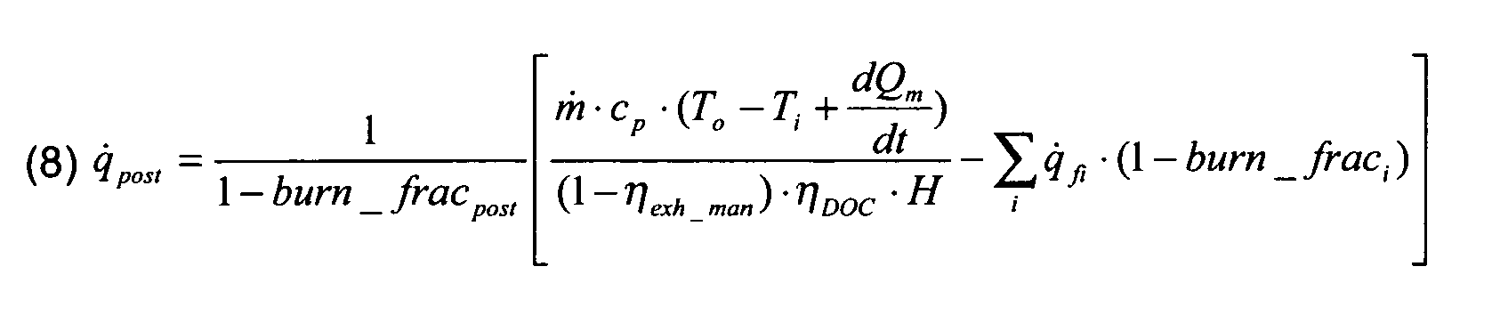
- Equation 8 1 1 - burn_frac post ⁇ m ⁇ c p ⁇ T o - T i + d Q m d t ( 1 - ⁇ exh_man ) ⁇ ⁇ DOC ⁇ H - ⁇ i q fi ⁇ 1 - burn_frac i
- a closed loop controller portion controls the open loop model associated to the particular oxidation catalyst. This means that the closed loop controller works using temperatures and not injected fuel quantities nor engine operating conditions.
- the filter time constants (T 1 and T 2 ) are related to the thermal inertia of the oxidation catalyst, the delay (T d ) is linked to the temperature distribution profile in the oxidation catalyst and s represents the "s-domain" of a Laplace transform function (that is, Pm is a Laplace transform). As described in relation to Fig. 3 , the temperature distribution profile mostly depends on the exhaust flow rate. T 1 , T 2 and T d can be derived from calibration tests by running an engine under different operating conditions and monitoring an oxidation catalyst.
- a step change on target temperature 30 of the oxidation catalyst outlet results in a change in actual temperature 32 of the oxidation catalyst outlet from a first steady state level 34 to a second steady state level 36.
- the change of the actual temperature 32 is not instantaneous but gradual, meaning that the arrival at the second steady state level 36 is a significant time from the original step change of the target temperature 30.
- Fig. 5 shows differences between the target temperature 30 and the actual temperature 32 during steady state conditions, this is simply because the graph used in Fig. 5 was produced from real data but not using a fully calibrated steady state model. It should be appreciated that Fig. 5 demonstrates the delay between a step change in the target temperature 30 and the actual temperature 32 also changing, the actual temperature values being unimportant.
- the delay shown in Fig. 5 is dependant on the exhaust mass flow rate and an example of the delay versus the exhaust mass flow rate for a particular oxidation catalyst is shown in Fig. 6 . This can be obtained by simply applying at different operating points a step change in the target temperature.
- the closed loop control system 40 comprises a closed loop internal process model 44, as represented by equation 9 above, a first perturbation rejection controller 46 and a second closed loop dynamics controller 48.
- the first controller 46 is used to control the perturbation rejection dynamics. If the process model 44 is perfect, it gives the response of the perturbation rejection. A perturbation can be an error not taken into account in the open loop model 42. All modelling errors are then rejected through the first controller 46.
- the first controller 46 is a first order lag filter. The associated time constant of a first order lag filter can be tuned for a compromise between best performance and robustness for the particular system.
- the second controller 48 is used to control the closed loop dynamics.
- the temperature set point is constant or changes very slowly and there is no advantage in improving the response to a change in the set point.
- second controller 48 is chosen to be a unity multiplier and has no effect. It can be envisaged that there may be a desire to improve the response time to the set point and, as such, the second controller 48 can then have an effect on the system.
- a target temperature 50 is set at the input to the system (the set point) and is fed through the second controller 48 to the internal process model 44 and the open loop model 42.
- the open loop model 42 will calculate an appropriate post fuel injection and deliver this accordingly.
- An outlet temperature is measured at the outlet to the oxidation catalyst in the system, which will correspond, in steady state at least, to the amount of post fuel injection.
- the internal process model 44 generates an estimation value which is then subtracted from the measured outlet temperature to generate an estimation error.
- the estimation error is fed in to the first controller 46 and the output of the first controller 46 is subtracted from the target temperature 50.
- the target temperature 50 can be simply adjusted as required and the outlet temperature will respond accordingly because delays and other cruciai factors have been explicitly calibrated As such, the outlet temperature can be ramped slowly from no exothermal reaction to the target temperature 50 for a sensitive DPF, such as cordierite.
Landscapes
- Engineering & Computer Science (AREA)
- Chemical & Material Sciences (AREA)
- Combustion & Propulsion (AREA)
- Mechanical Engineering (AREA)
- General Engineering & Computer Science (AREA)
- Materials Engineering (AREA)
- Health & Medical Sciences (AREA)
- Chemical Kinetics & Catalysis (AREA)
- Toxicology (AREA)
- Exhaust Gas After Treatment (AREA)
- Processes For Solid Components From Exhaust (AREA)
- Exhaust Gas Treatment By Means Of Catalyst (AREA)
Abstract
Description
- The present invention relates to outlet temperature control of an oxidation catalyst and particularly, but not exclusively, to outlet temperature control of an oxidation catalyst for use with a particulate filter regeneration system in diesel vehicle engines.
- Regeneration of Diesel Particulate Filters (DPF) requires high exhaust gas temperatures (>550°C), which are not usual during normal operation of a diesel passenger car. In order to obtain such temperatures, a late injection of fuel in an engine cycle, called a post fuel injection, into the exhaust phase is used to introduce unburned fuel into a Diesel Oxidation Catalyst (DOC) to generate an exothermal reaction. As the DOC is located before the DPF, the increase in temperature of exhaust gas caused by the exothermal reaction in the DOC burns off particulate material in the DPF, enabling additional particulate material to be filtered. In order to reduce thermal stress on the DPF, the outlet temperature of the DOC (inlet of DPF) needs to be controller to substantially around a target value.
- Control of the outlet temperature of the DOC is usually performed by a closed loop controller, such as a standard PID (Proportional-Integral-Derivative) controller, using a temperature sensor at the DOC outlet, the amount of post fuel injection being selected from a table which gives a function of both engine speed and engine load, as well as some compensations for transient conditions.
- This type of control has some disadvantages:
- it is a non-linear system as the amount of post fuel injection is not proportional to the temperature at the DOC outlet;
- variations of exhaust manifold temperatures and/or DOC inlet temperatures are not taken into account, which leads to lack of accuracy of the open-loop term;
- variations of ambient conditions may not be taken into account;
- delays introduced by the operation of DOC may amplify errors in closed-loop operation;
- transient operating conditions, such as variations in speed or load of the engine, usually give different DOC outlet temperatures than corresponding steady state conditions for same speed and load;
- any change in the calibration of EGR (Exhaust Gas Recirculation) rate, post injection timing, exhaust flow (throttling), requires a complete recalibration of the post fuel table; and
- the only way to change the DOC outlet target temperature is to duplicate the calibration, that is, one complete calibration for 600°C and a further complete calibration for 550°C.
- According to a first aspect of the present invention there is provided an oxidation catalyst outlet temperature control system for an engine having an exhaust means comprising an oxidation catalyst comprising:
- a temperature sensing means arranged to measure an inlet temperature of the oxidation catalyst;
- an exhaust flow rate measurement means for obtaining an exhaust mass flow rate; and
- a post fuel calculation means,
- wherein the post fuel calculation means calculates a value representing a post quantity of fuel to be introduced to generate an exothermic reaction in the oxidation catalyst based on a pre-determined desired outlet temperature of the oxidation catalyst, the calculation using a steady state model of the oxidation catalyst, the steady state model utilising the exhaust mass flow rate and the inlet temperature of the oxidation catalyst and instruction means to instruct the post quantity of fuel to be introduced to the engine.
- Preferably, the steady state model further utilises an initial fuel value corresponding to the fuel introduced to the engine before the post quantity of fuel, a first efficiency fraction corresponding to the fuel burnt between the vehicle engine and the oxidation catalyst, a second efficiency fraction corresponding to the fuel burnt in the engine and a pre-determined desired outlet temperature of the oxidation catalyst.
- Preferably, the steady state model corresponds to the following equation:


- Preferably, the oxidation catalyst temperature control system further comprises a memory means for storing calibrated values.
- Preferably, the first efficiency fraction, the second efficiency fraction and the exothermal efficiency for unburned fuel of the oxidation catalyst are obtained from the stored calibrated values.
- Preferably, the temperature sensing means further measures an engine outlet temperature and the relevant first efficiency fraction being selected based on engine outlet temperature from a set of pre-defined stored values defining the first efficiency fraction as a function of engine outlet temperature.
- Preferably, the value for the exothermal efficiency for unburned fuel of the oxidation catalyst is selected based on the inlet temperature of the oxidation catalyst from a set of pre-defined stored values defining a value for the exothermal efficiency for unburned fuel of the oxidation catalyst as a function of inlet temperature of the oxidation catalyst.
- Preferably, the relevant second efficiency fraction is selected based on an injection crank angle of the vehicle engine from a set of pre-defined stored values defining second efficiency fraction as a function of the injection crank angle.
- Preferably, the steady state model further utilises a transient compensation component.
- Preferably, the transient compensation component is a function of stored energy in the oxidation catalyst and exhaust mass flow rate.
- Preferably, the steady state model including the transient compensation component corresponds to the following equation:

- Preferably, the derivative dQm/dt is calculated by the difference between the stored energy Qm and a corresponding filtered value of Qm. Alternatively, Qm can be selected based on the exhaust mass flow rate.
- Preferably, the system further comprises a temperature based closed loop control.
- Preferably, the temperature sensing means also measures an outlet temperature of the oxidation catalyst.
- Preferably, the closed loop control comprises an internal process model.
- Preferably, the internal process model is a second order filter associated with a pure delay.
- Preferably, the second order filter is:

- Preferably, the closed loop control comprises a first controller which receives the difference between the internal process model and the measured outlet temperature of the oxidation catalyst and outputs a first controller value which is subtracted from a set outlet temperature to create the pre-determined desired outlet temperature To .
- Preferably, the first controller is a first order lag filter.
- Preferably, the closed loop control comprises a second controller which controls the pre-determined desired outlet temperature To before it is supplied to the internal process model and the steady state model.
- According to a second aspect of the present invention there is provided a method of controlling outlet temperature of an oxidation catalyst for an engine having an exhaust means comprising the steps of:
- (i) sensing temperature at an inlet of the oxidation catalyst;
- (ii) measuring an exhaust mass flow rate in the exhaust means;
- (iii) calculating a value representing a post quantity of fuel to be introduced to the engine to generate an exothermic reaction in the oxidation catalyst based on a pre-determined desired outlet temperature of the oxidation catalyst, the calculation representing the oxidation catalyst using a steady state model and utilising the exhaust mass flow rate and the inlet temperature of the oxidation catalyst; and
- (iv) instructing a quantity of fuel equivalent to the post fuel value to be introduced to the engine.
- Preferably, step (iii) further comprises utilising an initial fuel value corresponding to the fuel introduced to the engine before the post quantity of fuel, a first efficiency fraction corresponding to the fuel burnt between the vehicle engine and the oxidation catalyst, a second efficiency fraction corresponding to the fuel burnt in the engine and a pre-determined desired outlet temperature of the oxidation catalyst in the steady state model.
- Preferably, step (iii) represents the steady state model by calculating the following equation:


- Preferably, the method further comprises storing calibrated values in a suitable memory means.
- Preferably, step (iii) further comprises obtaining values for the first efficiency fraction, the second efficiency fraction and the exothermal efficiency for unburned fuel of the oxidation catalyst are from the stored calibrated values in the memory means.
- Preferably, the method further comprises the step of measuring an engine outlet temperature and selecting the first efficiency fraction based on the engine outlet temperature from a set of pre-defined stored calibrated values defining the first efficiency fraction as a function of engine outlet temperature.
- Preferably, the method further comprises the step of selecting the value for the exothermal efficiency for unburned fuel of the oxidation catalyst based on the inlet temperature of the oxidation catalyst from a set of pre-defined stored calibrated values defining the value for the exothermal efficiency for unburned fuel of the oxidation catalyst as a function of inlet temperature of the oxidation catalyst.
- Preferably, the method further comprises the step of selecting the relevant second efficiency fraction based on the injection crank angle of the vehicle engine from a set of pre-defined calibrated stored values defining second efficiency fraction as a function of the injection crank angle.
- Preferably, the method further comprises the step of compensating the steady state model for transients.
- Preferably, the step of compensating the steady state model for transients comprises calculating a compensating function dependent on stored energy in the oxidation catalyst
- Preferably, the steady state model of step (iii) including the compensating function involves calculating the following equation:

- Preferably, calculating the compensating function comprises calculating the derivative dQm/dt, which can be represented by the difference between the stored energy Qm and it's a corresponding filtered value of Qm. Alternatively, Qm can be selected based on the exhaust mass flow rate.
- Preferably, the method further comprises modifying the pre-determined desired outlet temperature using a closed loop feedback control.
- Preferably, the method further comprises the step of measuring an outlet temperature of the oxidation catalyst.
- Preferably, the closed loop feedback control comprises calculating an internal process model.
- Preferably, the internal process model is a second order filter associated with a pure delay.
- Preferably, the second order filter is:

- Preferably, the closed loop feedback control comprises performing a first controller calculation on the difference between the internal process model and the measured outlet temperature of the oxidation catalyst, outputting a first controller value, subtracting the first controller value from a set outlet temperature to create the pre-determined desired outlet temperature To .
- Preferably, the first controller calculation is a first order lag filter.
- Preferably, the closed loop control comprises performing a second controller calculation on the pre-determined desired outlet temperature To before it is supplied to the internal process model and the steady state model.
- According to a third aspect of the present invention there is provided a Diesel engine incorporating an oxidation catalyst outlet temperature control system according to the first aspect of the present invention for use in a particulate filter regeneration control system.
- Embodiments of the present invention will now be described, by way of example only, with reference to the drawings, in which:
-
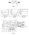
Fig. 1 is a representation of a oxidation catalyst in a particulate filter regeneration system; -
Fig. 2A, 2B and 2C are calibration graphs for use in a steady state model of the oxidation catalyst; -
Fig. 3 is a graph showing variations in temperature following a transient condition in a vehicle engine and a graph of temperature and oxidation catalyst length with respect to stored energy therein; -
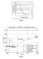
Fig. 4 is a graph of stored energy in a catalyst to exhaust mass flow rate for a particular oxidation catalyst and for use in a model of the oxidation catalyst; -
Fig. 5 is a graph showing a step change in desired output temperature and the actual output temperature; -
Fig. 6 is a graph of delay in change in output temperature versus exhaust mass flow rate; and -
Fig. 7 shows a flow diagram of a closed loop control system and the model of the oxidation catalyst. - As discussed above, prior art solutions to temperature control of a particulate filter regeneration system for a vehicle engine tend to combine measurement of temperature at an oxidation catalyst's outlet with a look-up table giving a defined "post" fuel injection according to engine speed and load.
- The present invention is based on an open-loop exothermal model of an oxidation catalyst. That is, a steady state model is used to calculate the quantity of "post" fuel required to generate an exothermal reaction in the oxidation catalyst which provides a required change in temperature at the oxidation catalyst outlet.
- The following description may refer to typical reciprocal vehicular engines, but it should be understood that the invention is capable of being applied to any engine which requires a particulate filter capable of regeneration through elevated temperatures. For example, rather than a reciprocal engine, the engine could be a rotary Wankel engine. Furthermore, the fuel source is also unimportant, although it will be appreciated that Diesel engines are most likely to have a particulate filter and, as such, a particulate filter regeneration system fitted.
- Referring to
Fig. 1 , the steady state model of anoxidation catalyst 10 can be represented by the energy associated with heat at the output of theoxidation catalyst 10 being equal to the heat energy at the input plus the heat energy from the exothermal reaction. This steady state model can be represented byequation 1.
- Where Q̇o is heat flow at the output of the
oxidation catalyst 10, Q̇i is heat flow at the input of theoxidation catalyst 10 and Q̇exo is heat flow due to an exothermal reaction in theoxidation catalyst 10. - As Q = ṁcpT,
equation 1 can be broken down as shown in equation 2.
- Where qfDOC is the unburned fuel at the oxidation catalyst inlet, H is the fuel heating value, η DOC is the oxidation catalyst efficiency for unburned fuel (exothermal), m is the exhaust mass flow rate, cp the specific heat of the exhaust gas, To is the oxidation catalyst outlet temperature and Ti is the oxidation catalyst inlet temperature.
- The exhaust mass flow rate m and the oxidation catalyst inlet temperature Ti can be easily measured with a gas flow meter and temperature sensor respectively. The oxidation catalyst outlet temperature To is the variable which must be controlled and therefore is pre-determined. As the specific heat of the exhaust gas cp and the fuel heating value H are constants, this leaves only the unburned fuel at the oxidation catalyst inlet qfDOC and the oxidation catalyst efficiency η DOC as unknown values.
- The unburned fuel at the oxidation catalyst inlet qfDOC depends on the amount of fuel injected into the engine cylinder, the percentage of fuel injected which is burnt in the cylinder and the percentage of fuel burnt prior to reaching the oxidation catalyst (unburnt fuel from the engine cylinder can be burnt in the exhaust manifold, if the manifold is sufficiently hot).
- So, the quantity of unburnt fuel exiting the cylinder can be represented by equation 3.

- Where qfEO is the unburned fuel at exhaust valve, taking into account the burned fraction of each injection pulse "i", including the "post" fuel injection pulse.
- We now have the quantity of fuel exiting the cylinder and equation 4 represents the unburned fuel at the oxidation catalyst inlet qfDOC.

- Where η exh_man is the "exothermal efficiency" of the exhaust manifold, which is the fraction of fuel burned between the exhaust valve and the
oxidation catalyst 10. - Equation 2 can now be rearranged to give the temperature difference between the inlet and outlet of the
oxidation catalyst 10, substituting equations 3 and 4 where appropriate, to give equation 5.
- As shown in
Fig. 2A , the traction of fuel burnt in each fuel injection burn_fraci can then be obtained from a calibration for the particular engine, dependent on the position of the fuel injection in the engine cycle. Furthermore, as shown inFig. 2B , the "exothermal efficiency" of the exhaust manifold η exh_man is dependant on the temperature at the exhaust manifold and, as such, a calibration can again be performed. Measuring the temperature at the exhaust manifold will therefore enable calculation of its "exothermal efficiency". In the same manner, as shown inFig. 2C , the oxidation catalyst efficiency η DOC is dependent on the inlet temperature of theoxidation catalyst 10. As this temperature is already being measured, or separately modelled, the inlet temperature can be used to also calculate the oxidation catalyst efficiency. - Rearranging equation 5, we can obtain the required post fuel pulse to give the desired output temperature of the oxidation catalyst, as shown in equation 6.

- To further improve the accuracy of the required post fuel injection, transient conditions may be considered. A certain amount of energy can be stored in the
oxidation catalyst 10 depending on the flow conditions and the physical characteristics of thecatalyst 10. A lower flow rate tends to store energy in the catalyst and a higher flow rate tends to release that stored energy, which gives the oxidation catalyst 10 a thermal inertia. Because the amount of stored energy can vary with flow rate, a transient from low flow rate to high flow rate can release the stored energy giving higher outlet temperatures than desired. If the outlet temperature of the oxidation catalyst is too high, the catalyst itself or a downstream particulate filter can be damaged. - Referring to
Fig. 3 , a transient in exhaustmass flow rate 20 is shown going from a steady state value of around 10g/s to about 50g/s before settling at around 33g/s. As a result of the increased flow,catalyst outlet temperature 22 rises from around 600°C to around 680°C before settling back to nearly 600°C. Shadedarea 24, under thecatalyst outlet temperature 22, represents the release of the stored energy in theoxidation catalyst 10 due to the higher flow rate. Themiddle point temperature 26, that is the temperature in the middle of the catalyst, shows that the temperature distribution along the catalyst length changes with flow. This is represented by the graph of catalyst length versus temperature at the right hand side ofFig. 3 . - Introducing this transient effect in equation 5 gives:

Fig. 4 . - Once again, rearranging equation 7 to give the post fuel quantity gives equation 8.
- One of the biggest advantages of the open loop model as described above in terms of controls is the linearization of the system. This means that a temperature difference between inlet and outlet is selected and the same temperature difference is measured at the output of the oxidation catalyst, if the model is accurate. It also means that if the desired temperature difference is increased, the measured temperature increases by the same value.
- In the real life operation of a particulate filter regeneration system, factors may cause the calibration of the open loop model to become inaccurate, such as any inaccuracies in assumptions made in the system or changes to the oxidation catalyst over time. As such, a closed loop control portion can be added to the system.
- In this example, a closed loop controller portion controls the open loop model associated to the particular oxidation catalyst. This means that the closed loop controller works using temperatures and not injected fuel quantities nor engine operating conditions.
- In transient operation, the oxidation catalyst is modelled as a second order filter associated to a delay :
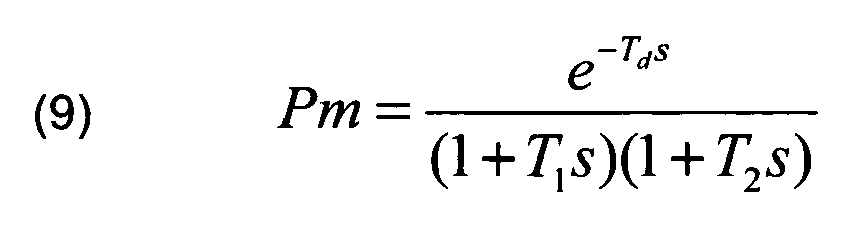
- The filter time constants (T1 and T2) are related to the thermal inertia of the oxidation catalyst, the delay (Td) is linked to the temperature distribution profile in the oxidation catalyst and s represents the "s-domain" of a Laplace transform function (that is, Pm is a Laplace transform). As described in relation to
Fig. 3 , the temperature distribution profile mostly depends on the exhaust flow rate. T1, T2 and Td can be derived from calibration tests by running an engine under different operating conditions and monitoring an oxidation catalyst. - Referring to
Fig, 5 , a step change ontarget temperature 30 of the oxidation catalyst outlet, results in a change inactual temperature 32 of the oxidation catalyst outlet from a firststeady state level 34 to a secondsteady state level 36. As can be clearly seen fromFig. 5 , there is a delay from the step change on thetarget temperature 30 to the increase of theactual temperature 32. Furthermore, the change of theactual temperature 32 is not instantaneous but gradual, meaning that the arrival at the secondsteady state level 36 is a significant time from the original step change of thetarget temperature 30. AlthoughFig. 5 shows differences between thetarget temperature 30 and theactual temperature 32 during steady state conditions, this is simply because the graph used inFig. 5 was produced from real data but not using a fully calibrated steady state model. It should be appreciated thatFig. 5 demonstrates the delay between a step change in thetarget temperature 30 and theactual temperature 32 also changing, the actual temperature values being unimportant. - The delay shown in
Fig. 5 is dependant on the exhaust mass flow rate and an example of the delay versus the exhaust mass flow rate for a particular oxidation catalyst is shown inFig. 6 . This can be obtained by simply applying at different operating points a step change in the target temperature. - As the delay is not negligible compared to the time constants of the process, classical control approaches, such as PID (Proportional-Integral-Derivative) controllers, are not appropriate. Accordingly, the closed loop control is performed using an internal model of the system.
- Referring now to
Fig. 7 , a flow diagram showing a closedloop control system 40 and a steady stateoxidation catalyst model 42, as described with relation to the open loop control above, is shown. The closedloop control system 40 comprises a closed loopinternal process model 44, as represented by equation 9 above, a firstperturbation rejection controller 46 and a second closedloop dynamics controller 48. - Compared to classical control approaches, there are two
controllers 46 48 instead of one, as would be found in a typical PID controller. - The
first controller 46 is used to control the perturbation rejection dynamics. If theprocess model 44 is perfect, it gives the response of the perturbation rejection. A perturbation can be an error not taken into account in theopen loop model 42. All modelling errors are then rejected through thefirst controller 46. In this example, thefirst controller 46 is a first order lag filter. The associated time constant of a first order lag filter can be tuned for a compromise between best performance and robustness for the particular system. - The
second controller 48 is used to control the closed loop dynamics. In the case of a DPF regeneration system, the temperature set point is constant or changes very slowly and there is no advantage in improving the response to a change in the set point. As such,second controller 48 is chosen to be a unity multiplier and has no effect. It can be envisaged that there may be a desire to improve the response time to the set point and, as such, thesecond controller 48 can then have an effect on the system. - In use, a
target temperature 50 is set at the input to the system (the set point) and is fed through thesecond controller 48 to theinternal process model 44 and theopen loop model 42. Theopen loop model 42 will calculate an appropriate post fuel injection and deliver this accordingly. An outlet temperature is measured at the outlet to the oxidation catalyst in the system, which will correspond, in steady state at least, to the amount of post fuel injection. Theinternal process model 44 generates an estimation value which is then subtracted from the measured outlet temperature to generate an estimation error. The estimation error is fed in to thefirst controller 46 and the output of thefirst controller 46 is subtracted from thetarget temperature 50. - With closed
loop control system 40, thetarget temperature 50 can be simply adjusted as required and the outlet temperature will respond accordingly because delays and other cruciai factors have been explicitly calibrated As such, the outlet temperature can be ramped slowly from no exothermal reaction to thetarget temperature 50 for a sensitive DPF, such as cordierite. - It will be appreciated that, although the specific example given above relates to a Diesel Particulate Filter, the present invention can be applied to any application for outlet temperature control of an oxidation catalyst. For example, elevated outlet temperatire control of an oxidation catalyst may be useful with Lean Nitrous oxides (NOx) Traps (LNT) desulfation systems and for fast exhaust heat-up.
- Further modifications and improvements may be made without departing from the scope of the present invention.
Claims (43)
- An oxidation catalyst temperature control system for an engine having an exhaust means including an oxidation catalyst comprising:a temperature sensing means arranged to measure an inlet temperature of the oxidation catalyst;an exhaust flow rate measurement means for obtaining an exhaust mass flow rate; anda post fuel calculation means,wherein the post fuel calculation means calculates a value representing a post quantity of fuel to be introduced to generate an exothermic reaction in the oxidation catalyst based on a pre-determined desired outlet temperature of the oxidation catalyst, the calculation using a steady state model of the oxidation catalyst, the steady state model utilising the exhaust mass flow rate and the inlet temperature of the oxidation catalyst and instruction means to instruct the post quantity of fuel to be introduced to the engine.
- A system as claimed in claim 1, wherein the steady state model further utilises an initial fuel value corresponding to the fuel introduced to the engine before the post quantity of fuel, a first efficiency fraction corresponding to the fuel burnt between the vehicle engine and the oxidation catalyst, a second efficiency fraction corresponding to the fuel burnt in the engine and a pre-determined desired outlet temperature of the oxidation catalyst.
- A system as claimed in claim 2, wherein the steady state model corresponds to the following equation:


- A system as claimed in any of claims 1 to 3, wherein the oxidation catalyst temperature control system further comprises a memory means for storing calibrated values.
- A system as claimed in claim 4, wherein the first efficiency fraction, the second efficiency fraction and the exothermal efficiency for unburned fuel of the oxidation catalyst are obtained from the stored calibrated values.
- A system as claimed in any of claims 2 to 5, wherein the temperature sensing means further measures an engine outlet temperature and the relevant first efficiency fraction being selected based on engine outlet temperature from a set of pre-defined stored values defining the first efficiency fraction as a function of engine outlet temperature.
- A system as claimed in any of claims 2 to 6, wherein the value for the exothermal efficiency for unburned fuel of the oxidation catalyst is selected based on the inlet temperature of the oxidation catalyst from a set of pre-defined stored values defining a value for the exothermal efficiency for unburned fuel of the oxidation catalyst as a function of inlet temperature of the oxidation catalyst.
- A system as claimed in any of claims 2 to 7, wherein the relevant second efficiency fraction is selected based on an injection crank angle of the vehicle engine from a set of pre-defined stored values defining second efficiency fraction as a function of the injection crank angle.
- A system as claimed in any of claims 1 to 8, wherein the steady state model further utilises a transient compensation component.
- A system as claimed in claim 9, wherein the transient compensation component is a function of stored energy in the oxidation catalyst and exhaust mass flow rate.
- A system as claimed in claim 10, wherein the steady state model including the transient compensation component corresponds to the following equation:

- A system as claimed in claim 11, wherein the derivative dQm/dt is calculated by the difference between the stored energy Qm and a corresponding filtered value of Qm.
- A system as claimed in claim 11, wherein Qm is selected based on a function of exhaust mass flow rate.
- A system as claimed in any of claims 1 to 13, wherein the system further comprises a temperature based closed loop control.
- A system as claimed in any of claims 1 to 14, wherein the temperature sensing means also measures an outlet temperature of the oxidation catalyst.
- A system as claimed in claim 14 or 15, wherein the closed loop control comprises an internal process model.
- A system as claimed in claim 16, wherein the internal process model is a second order filter associated with a pure delay.
- A system as claimed in claim 17, wherein the second order filter is:

- A system as claimed in any of claims 14 to 18, wherein the closed loop control comprises a first controller which receives the difference between the internal process model and the measured outlet temperature of the oxidation catalyst and outputs a first controller value which is subtracted from a set outlet temperature to create the pre-determined desired outlet temperature To .
- A system as claimed in claim 19, wherein the first controller is a first order lag filter.
- A system as claimed in any of claims 14 to 20, wherein the closed loop control comprises a second controller which controls the pre-determined desired outlet temperature To before it is supplied to the internal process model and the steady state model.
- A method of controlling a outlet temperature of an oxidation catalyst for an engine having an exhaust means including an oxidation catalyst comprising the steps of:(i) sensing temperature at an inlet of the oxidation catalyst;(ii) measuring an exhaust mass flow rate in the exhaust means;(iii) calculating a value representing a post quantity of fuel to be introduced to the engine to generate an exothermic reaction in the oxidation catalyst based on a pre-determined desired outlet temperature of the oxidation catalyst, the calculation representing the oxidation catalyst using a steady state model and utilising the exhaust mass flow rate and the inlet temperature of the oxidation catalyst; and(iv) instructing a quantity of fuel equivalent to the post fuel value to be introduced to the engine.
- A method as claimed in claim 22, wherein step (iii) further comprises utilising an initial fuel value corresponding to the fuel introduced to the engine before the post quantity of fuel, a first efficiency fraction corresponding to the fuel burnt between the vehicle engine and the oxidation catalyst, a second efficiency fraction corresponding to the fuel burnt in the engine and a pre-determined desired outlet temperature of the oxidation catalyst in the steady state model.
- A method as claimed in claim 21, wherein step (iii) represents the steady state model by calculating the following equation:


- A method as claimed in any of claims 22 to 24, wherein the method further comprises storing calibrated values in a suitable memory means.
- A method as claimed in claim 25, wherein step (iii) further comprises obtaining values for the first efficiency fraction, the second efficiency fraction and the exothermal efficiency for unburned fuel of the oxidation catalyst are from the stored calibrated values in the memory means.
- A method as claimed in any of claims 22 to 26, wherein the method further comprises the step of measuring an engine outlet temperature and selecting the first efficiency fraction based on the engine outlet temperature from a set of pre-defined stored calibrated values defining the first efficiency fraction as a function of engine outlet temperature.
- A method as claimed in any of claims 22 to 27, wherein the method further comprises the step of selecting the value for the exothermal efficiency for unburned fuel of the oxidation catalyst based on the inlet temperature of the oxidation catalyst from a set of pre-defined stored calibrated values defining the value for the exothermal efficiency for unburned fuel of the oxidation catalyst as a function of inlet temperature of the oxidation catalyst.
- A method as claimed in any of claims 22 to 28, wherein the method further comprises the step of selecting the relevant second efficiency fraction based on the injection crank angle of the vehicle engine from a set of pre-defined calibrated stored values defining second efficiency fraction as a function of the injection crank angle.
- A method as claimed in any of claims 22 to 29, wherein the method further comprises the step of compensating the steady state model for transients.
- A method as claimed in claim 30, wherein the step of compensating the steady state model for transients comprises calculating a compensating function dependent on stored energy in the oxidation catalyst.
- A method as claimed in claim 31, wherein the steady state model of step (iii) including the compensating function involves calculating the following equation:

- A method as claimed in claim 32, wherein calculating the compensating function comprises calculating the derivative dQm/dt, which can be represented by the difference between the stored energy Qm and it's a corresponding filtered value of Qm.
- A method as claimed in claim 32, wherein Qm can be selected based on a function of exhaust mass flow rate.
- A method as claimed in any of claims 22 to 34, wherein the method further comprises modifying the pre-determined desired outlet temperature using a closed loop feedback control.
- A method as claimed in any of claims 22 to 35, wherein the method further comprises the step of measuring an outlet temperature of the oxidation catalyst.
- A method as claimed in claim 35 or claim 36, wherein the closed loop feedback control comprises calculating an internal process model.
- A method as claimed in claim 37, wherein the internal process model is a second order filter associated with a pure delay.
- A method as claimed in claim 38, wherein the second order filter is:

- A method as claimed in any of claims 35 to 39, wherein the closed loop feedback control comprises performing a first controller calculation on the difference between the internal process model and the measured outlet temperature of the oxidation catalyst, outputting a first controller value, subtracting the first controller value from a set outlet temperature to create the pre-determined desired outlet temperature To .
- A method as claimed in claim 40, wherein the first controller calculation is a first order lag filter.
- A method as claimed in any of claims 35 to 41, wherein the closed loop control comprises performing a second controller calculation on the pre-determined desired outlet temperature To before it is supplied to the internal process model and the steady state model.
- A Diesel engine incorporating an oxidation catalyst outlet temperature control system according to claims 1 to 21 for use in a particulate filter regeneration control system.
Priority Applications (4)
| Application Number | Priority Date | Filing Date | Title |
|---|---|---|---|
| AT07253089T ATE507381T1 (en) | 2007-07-31 | 2007-07-31 | SYSTEM AND METHOD FOR CONTROLLING EXHAUST GAS TEMPERATURE OF AN OXIDATION CATALYST |
| DE602007014207T DE602007014207D1 (en) | 2007-07-31 | 2007-07-31 | System and method for exhaust gas temperature control of an oxidation catalyst |
| EP07253089A EP2031217B1 (en) | 2007-07-31 | 2007-07-31 | System and method for outlet temperature control of an oxidation catalyst |
| PCT/EP2008/063064 WO2009016266A2 (en) | 2007-07-31 | 2008-09-30 | System and method for outlet temperature control of an oxidation catalyst |
Applications Claiming Priority (1)
| Application Number | Priority Date | Filing Date | Title |
|---|---|---|---|
| EP07253089A EP2031217B1 (en) | 2007-07-31 | 2007-07-31 | System and method for outlet temperature control of an oxidation catalyst |
Publications (2)
| Publication Number | Publication Date |
|---|---|
| EP2031217A1 true EP2031217A1 (en) | 2009-03-04 |
| EP2031217B1 EP2031217B1 (en) | 2011-04-27 |
Family
ID=38819674
Family Applications (1)
| Application Number | Title | Priority Date | Filing Date |
|---|---|---|---|
| EP07253089A Active EP2031217B1 (en) | 2007-07-31 | 2007-07-31 | System and method for outlet temperature control of an oxidation catalyst |
Country Status (4)
| Country | Link |
|---|---|
| EP (1) | EP2031217B1 (en) |
| AT (1) | ATE507381T1 (en) |
| DE (1) | DE602007014207D1 (en) |
| WO (1) | WO2009016266A2 (en) |
Cited By (6)
| Publication number | Priority date | Publication date | Assignee | Title |
|---|---|---|---|---|
| WO2012092974A1 (en) * | 2011-01-07 | 2012-07-12 | Delphi Technologies Holding S.À.R.L. | Internal combustion engine with exhaust after treatment and its method of operation |
| EP2479409A1 (en) * | 2011-01-25 | 2012-07-25 | Peugeot Citroën Automobiles SA | Method for controlling the temperature of exhaust gases in order to optimise the regeneration of a particle filter |
| EP2647815A1 (en) | 2012-04-05 | 2013-10-09 | Delphi Technologies Holding S.à.r.l. | Lean nox trap desulfation process |
| US9046021B2 (en) | 2013-06-05 | 2015-06-02 | Tenneco Automotive Operating Company Inc. | Exhaust treatment regeneration control system |
| WO2016042399A1 (en) * | 2014-09-17 | 2016-03-24 | Toyota Jidosha Kabushiki Kaisha | Control device and control method for internal combustion engine |
| GB2592624A (en) * | 2020-03-04 | 2021-09-08 | Delphi Automotive Systems Lux | Method for monitoring an exhaust after treatment device |
Families Citing this family (8)
| Publication number | Priority date | Publication date | Assignee | Title |
|---|---|---|---|---|
| FR2943720A1 (en) * | 2009-03-24 | 2010-10-01 | Peugeot Citroen Automobiles Sa | Particle filter regeneration method for diesel engine of vehicle, involves adjusting hydrocarbon flow according to characteristic parameter of exhaust gas, where parameter is instantaneous oxygen concentration or richness of exhaust gas |
| US8452518B2 (en) | 2010-04-28 | 2013-05-28 | GM Global Technology Operations LLC | Post-combustion fuel injection control systems and methods |
| US8474245B2 (en) | 2010-04-28 | 2013-07-02 | GM Global Technology Operations LLC | Exhaust and component temperature estimation systems and methods |
| US8549839B2 (en) | 2010-04-28 | 2013-10-08 | GM Global Technology Operations LLC | Hydrocarbon energy storage and release control systems and methods |
| DE102010037431A1 (en) | 2010-09-09 | 2012-03-15 | Ford Global Technologies, Llc. | Method for adjusting an exothermic reaction in the exhaust system of a motor vehicle |
| DE102010038175A1 (en) | 2010-10-14 | 2012-04-19 | Ford Global Technologies, Llc. | A method of adjusting a lean NOx trap in an exhaust system of a motor vehicle |
| US8818691B2 (en) | 2012-03-13 | 2014-08-26 | GM Global Technology Operations LLC | Exhaust system and method for controlling temperature of exhaust gas in an exhaust system |
| DE102022208309A1 (en) * | 2022-08-10 | 2024-02-15 | Robert Bosch Gesellschaft mit beschränkter Haftung | Method for limiting the air filling of an internal combustion engine |
Citations (5)
| Publication number | Priority date | Publication date | Assignee | Title |
|---|---|---|---|---|
| DE20023426U1 (en) * | 2000-07-07 | 2004-04-29 | Daimlerchrysler Ag | IC engines esp. for motor vehicles with fuel after-injection for particle filter regeneration regulated dependent upon exhaust temperature in front of filter |
| US20040226288A1 (en) * | 2003-05-16 | 2004-11-18 | Denso Corporation | Exhaust gas purification system of internal combustion engine |
| US20050228572A1 (en) * | 2002-12-13 | 2005-10-13 | Matthias Mansbart | Catalyst temperature modelling during exotermic operation |
| US20050241301A1 (en) * | 2004-04-30 | 2005-11-03 | Denso Corporation | Exhaust cleaning device of internal combustion engine |
| US20050284131A1 (en) * | 2004-06-29 | 2005-12-29 | Stefan Forthmann | Method for metering a fuel into an exhaust duct of an internal combustion engine and a device for implementing the method |
Family Cites Families (1)
| Publication number | Priority date | Publication date | Assignee | Title |
|---|---|---|---|---|
| FR2907508B1 (en) * | 2006-10-24 | 2008-12-05 | Renault Sas | METHOD FOR CONTROLLING THE TEMPERATURE OF GASES IN AN EXHAUST CIRCUIT OF INTERNAL COMBUSTION ENGINE. |
-
2007
- 2007-07-31 EP EP07253089A patent/EP2031217B1/en active Active
- 2007-07-31 DE DE602007014207T patent/DE602007014207D1/en active Active
- 2007-07-31 AT AT07253089T patent/ATE507381T1/en not_active IP Right Cessation
-
2008
- 2008-09-30 WO PCT/EP2008/063064 patent/WO2009016266A2/en not_active Ceased
Patent Citations (5)
| Publication number | Priority date | Publication date | Assignee | Title |
|---|---|---|---|---|
| DE20023426U1 (en) * | 2000-07-07 | 2004-04-29 | Daimlerchrysler Ag | IC engines esp. for motor vehicles with fuel after-injection for particle filter regeneration regulated dependent upon exhaust temperature in front of filter |
| US20050228572A1 (en) * | 2002-12-13 | 2005-10-13 | Matthias Mansbart | Catalyst temperature modelling during exotermic operation |
| US20040226288A1 (en) * | 2003-05-16 | 2004-11-18 | Denso Corporation | Exhaust gas purification system of internal combustion engine |
| US20050241301A1 (en) * | 2004-04-30 | 2005-11-03 | Denso Corporation | Exhaust cleaning device of internal combustion engine |
| US20050284131A1 (en) * | 2004-06-29 | 2005-12-29 | Stefan Forthmann | Method for metering a fuel into an exhaust duct of an internal combustion engine and a device for implementing the method |
Non-Patent Citations (1)
| Title |
|---|
| HIROSHI INAGAKI ET AL: "AN ADAPTIVE FUEL INJECTION CONTROL WITH INTERNAL MODEL IN AUTOMOTIVE ENGINES", SIGNAL PROCESSING AND SYSTEM CONTROL, FACTORY AUTOMATION. PACIFIC GROVE, NOV. 27 - 30, 1990, PROCEEDINGS OF THE ANNUAL CONFERENCE OF THE INDUSTRIAL ELECTRONICS SOCIETY. (IECON), NEW YORK, IEEE, US, vol. VOL. 1 CONF. 16, 27 November 1990 (1990-11-27), pages 78 - 83, XP000217101, ISBN: 0-87942-600-4 * |
Cited By (14)
| Publication number | Priority date | Publication date | Assignee | Title |
|---|---|---|---|---|
| CN103282627A (en) * | 2011-01-07 | 2013-09-04 | 德尔福技术控股有限公司 | Internal combustion engine with exhaust after treatment and its method of operation |
| WO2012092974A1 (en) * | 2011-01-07 | 2012-07-12 | Delphi Technologies Holding S.À.R.L. | Internal combustion engine with exhaust after treatment and its method of operation |
| CN103282627B (en) * | 2011-01-07 | 2016-03-16 | 德尔福国际运营卢森堡有限公司 | Internal combustion engine with exhaust aftertreatment and method of operation thereof |
| US9567890B2 (en) | 2011-01-07 | 2017-02-14 | Delphi International Operations Luxembourg S.A.R.L. | Internal combustion engine with exhaust aftertreatment and its method of operation |
| EP2479409A1 (en) * | 2011-01-25 | 2012-07-25 | Peugeot Citroën Automobiles SA | Method for controlling the temperature of exhaust gases in order to optimise the regeneration of a particle filter |
| FR2970737A1 (en) * | 2011-01-25 | 2012-07-27 | Peugeot Citroen Automobiles Sa | METHOD FOR CONTROLLING THE EXHAUST GAS TEMPERATURE TO OPTIMIZE THE REGENERATION OF A PARTICLE FILTER |
| US9429088B2 (en) | 2012-04-05 | 2016-08-30 | Delphi International Operations Luxembourg S A.R.L. | Lean NOx trap desulfation process |
| EP2647815A1 (en) | 2012-04-05 | 2013-10-09 | Delphi Technologies Holding S.à.r.l. | Lean nox trap desulfation process |
| WO2013149782A1 (en) | 2012-04-05 | 2013-10-10 | Delphi Technologies Holding S.À.R.L. | Lean nox trap desulfation process |
| US9046021B2 (en) | 2013-06-05 | 2015-06-02 | Tenneco Automotive Operating Company Inc. | Exhaust treatment regeneration control system |
| JP2016061188A (en) * | 2014-09-17 | 2016-04-25 | トヨタ自動車株式会社 | Control device for internal combustion engine |
| WO2016042399A1 (en) * | 2014-09-17 | 2016-03-24 | Toyota Jidosha Kabushiki Kaisha | Control device and control method for internal combustion engine |
| GB2592624A (en) * | 2020-03-04 | 2021-09-08 | Delphi Automotive Systems Lux | Method for monitoring an exhaust after treatment device |
| GB2592624B (en) * | 2020-03-04 | 2024-08-28 | Phinia Delphi Luxembourg Sarl | Method for monitoring an exhaust after treatment device |
Also Published As
| Publication number | Publication date |
|---|---|
| DE602007014207D1 (en) | 2011-06-09 |
| EP2031217B1 (en) | 2011-04-27 |
| ATE507381T1 (en) | 2011-05-15 |
| WO2009016266A3 (en) | 2009-04-09 |
| WO2009016266A8 (en) | 2010-03-11 |
| WO2009016266A2 (en) | 2009-02-05 |
Similar Documents
| Publication | Publication Date | Title |
|---|---|---|
| EP2031217B1 (en) | System and method for outlet temperature control of an oxidation catalyst | |
| US8490388B2 (en) | System and method for outlet temperature control of an oxidation catalyst | |
| US7104049B2 (en) | Exhaust gas purifying system and regeneration end determining method | |
| EP2543845A1 (en) | Method for determination of exhaust back pressure | |
| CN110552803B (en) | Method for regulating the filling level of a storage device for exhaust gas components of a catalytic converter | |
| KR102664186B1 (en) | Method for determining a maximum storage capacity of an exhaust gas component accumulator of a catalytic converter | |
| Huang et al. | Exhaust temperature control for safe and efficient thermal regeneration of diesel particulate filter | |
| US8631644B2 (en) | Method for operating post injections of fuel in an internal combustion engine | |
| EP2735486A1 (en) | A multivariable control system | |
| CN109937292A (en) | Method for adjusting the compactedness of the reservoir for waste gas component of catalyst converter | |
| KR102750940B1 (en) | Method for controlling a filling level of an exhaust gas component accumulator of a catalytic converter in an exhaust gas of an internal combustion engine | |
| CN111379635B (en) | Method and control device for regulating the filling state of a catalytic converter storage device when the sensor is not ready | |
| US20050217256A1 (en) | Exhaust gas purification system of internal combustion engine | |
| US9322357B2 (en) | Soot accumulation model for setpoint modification | |
| US11788461B2 (en) | Turbocharger control with overspeed protection | |
| CN108425754B (en) | Method and control device for controlling the opening state of an exhaust flap of an internal combustion engine | |
| JP2006509947A (en) | Catalyst temperature modeling in exothermic operation | |
| CN111379636A (en) | Method for distinguishing between model inaccuracy and lambda offset for model-assisted adjustment of catalyst fill level | |
| JP2010510440A (en) | Method for determining the amount of fuel injected into an exhaust pipe to regenerate a particulate removal filter | |
| US20190162102A1 (en) | Control of aftertreatment of an internal combustion engine | |
| CN111379638B (en) | Method for regulating the filling of an exhaust gas component storage device of a catalytic converter | |
| CN113985942B (en) | DPF regeneration temperature control system and method | |
| Guardiola et al. | Fast estimation of diesel oxidation catalysts inlet gas temperature | |
| Fulton et al. | Exhaust manifold temperature observer model | |
| JP4629758B2 (en) | System and method for outlet temperature control of an oxidation catalyst |
Legal Events
| Date | Code | Title | Description |
|---|---|---|---|
| PUAI | Public reference made under article 153(3) epc to a published international application that has entered the european phase |
Free format text: ORIGINAL CODE: 0009012 |
|
| 17P | Request for examination filed |
Effective date: 20080214 |
|
| AK | Designated contracting states |
Kind code of ref document: A1 Designated state(s): AT BE BG CH CY CZ DE DK EE ES FI FR GB GR HU IE IS IT LI LT LU LV MC MT NL PL PT RO SE SI SK TR |
|
| AX | Request for extension of the european patent |
Extension state: AL BA HR MK RS |
|
| AKX | Designation fees paid |
Designated state(s): AT BE BG CH CY CZ DE DK EE ES FI FR GB GR HU IE IS IT LI LT LU LV MC MT NL PL PT RO SE SI SK TR |
|
| RAP1 | Party data changed (applicant data changed or rights of an application transferred) |
Owner name: DELPHI TECHNOLOGIES HOLDING S.A.R.L. |
|
| GRAP | Despatch of communication of intention to grant a patent |
Free format text: ORIGINAL CODE: EPIDOSNIGR1 |
|
| GRAS | Grant fee paid |
Free format text: ORIGINAL CODE: EPIDOSNIGR3 |
|
| GRAA | (expected) grant |
Free format text: ORIGINAL CODE: 0009210 |
|
| AK | Designated contracting states |
Kind code of ref document: B1 Designated state(s): AT BE BG CH CY CZ DE DK EE ES FI FR GB GR HU IE IS IT LI LT LU LV MC MT NL PL PT RO SE SI SK TR |
|
| REG | Reference to a national code |
Ref country code: GB Ref legal event code: FG4D |
|
| REG | Reference to a national code |
Ref country code: CH Ref legal event code: EP |
|
| REG | Reference to a national code |
Ref country code: IE Ref legal event code: FG4D |
|
| REF | Corresponds to: |
Ref document number: 602007014207 Country of ref document: DE Date of ref document: 20110609 Kind code of ref document: P |
|
| REG | Reference to a national code |
Ref country code: DE Ref legal event code: R096 Ref document number: 602007014207 Country of ref document: DE Effective date: 20110609 |
|
| REG | Reference to a national code |
Ref country code: NL Ref legal event code: VDEP Effective date: 20110427 |
|
| LTIE | Lt: invalidation of european patent or patent extension |
Effective date: 20110427 |
|
| REG | Reference to a national code |
Ref country code: DE Ref legal event code: R082 Ref document number: 602007014207 Country of ref document: DE |
|
| PG25 | Lapsed in a contracting state [announced via postgrant information from national office to epo] |
Ref country code: PT Free format text: LAPSE BECAUSE OF FAILURE TO SUBMIT A TRANSLATION OF THE DESCRIPTION OR TO PAY THE FEE WITHIN THE PRESCRIBED TIME-LIMIT Effective date: 20110829 Ref country code: SE Free format text: LAPSE BECAUSE OF FAILURE TO SUBMIT A TRANSLATION OF THE DESCRIPTION OR TO PAY THE FEE WITHIN THE PRESCRIBED TIME-LIMIT Effective date: 20110427 Ref country code: LT Free format text: LAPSE BECAUSE OF FAILURE TO SUBMIT A TRANSLATION OF THE DESCRIPTION OR TO PAY THE FEE WITHIN THE PRESCRIBED TIME-LIMIT Effective date: 20110427 |
|
| PG25 | Lapsed in a contracting state [announced via postgrant information from national office to epo] |
Ref country code: BE Free format text: LAPSE BECAUSE OF FAILURE TO SUBMIT A TRANSLATION OF THE DESCRIPTION OR TO PAY THE FEE WITHIN THE PRESCRIBED TIME-LIMIT Effective date: 20110427 Ref country code: SI Free format text: LAPSE BECAUSE OF FAILURE TO SUBMIT A TRANSLATION OF THE DESCRIPTION OR TO PAY THE FEE WITHIN THE PRESCRIBED TIME-LIMIT Effective date: 20110427 Ref country code: IS Free format text: LAPSE BECAUSE OF FAILURE TO SUBMIT A TRANSLATION OF THE DESCRIPTION OR TO PAY THE FEE WITHIN THE PRESCRIBED TIME-LIMIT Effective date: 20110827 Ref country code: FI Free format text: LAPSE BECAUSE OF FAILURE TO SUBMIT A TRANSLATION OF THE DESCRIPTION OR TO PAY THE FEE WITHIN THE PRESCRIBED TIME-LIMIT Effective date: 20110427 Ref country code: LV Free format text: LAPSE BECAUSE OF FAILURE TO SUBMIT A TRANSLATION OF THE DESCRIPTION OR TO PAY THE FEE WITHIN THE PRESCRIBED TIME-LIMIT Effective date: 20110427 Ref country code: ES Free format text: LAPSE BECAUSE OF FAILURE TO SUBMIT A TRANSLATION OF THE DESCRIPTION OR TO PAY THE FEE WITHIN THE PRESCRIBED TIME-LIMIT Effective date: 20110807 Ref country code: AT Free format text: LAPSE BECAUSE OF FAILURE TO SUBMIT A TRANSLATION OF THE DESCRIPTION OR TO PAY THE FEE WITHIN THE PRESCRIBED TIME-LIMIT Effective date: 20110427 Ref country code: CY Free format text: LAPSE BECAUSE OF FAILURE TO SUBMIT A TRANSLATION OF THE DESCRIPTION OR TO PAY THE FEE WITHIN THE PRESCRIBED TIME-LIMIT Effective date: 20110427 Ref country code: GR Free format text: LAPSE BECAUSE OF FAILURE TO SUBMIT A TRANSLATION OF THE DESCRIPTION OR TO PAY THE FEE WITHIN THE PRESCRIBED TIME-LIMIT Effective date: 20110728 |
|
| PG25 | Lapsed in a contracting state [announced via postgrant information from national office to epo] |
Ref country code: NL Free format text: LAPSE BECAUSE OF FAILURE TO SUBMIT A TRANSLATION OF THE DESCRIPTION OR TO PAY THE FEE WITHIN THE PRESCRIBED TIME-LIMIT Effective date: 20110427 Ref country code: MT Free format text: LAPSE BECAUSE OF FAILURE TO SUBMIT A TRANSLATION OF THE DESCRIPTION OR TO PAY THE FEE WITHIN THE PRESCRIBED TIME-LIMIT Effective date: 20110427 |
|
| PG25 | Lapsed in a contracting state [announced via postgrant information from national office to epo] |
Ref country code: CZ Free format text: LAPSE BECAUSE OF FAILURE TO SUBMIT A TRANSLATION OF THE DESCRIPTION OR TO PAY THE FEE WITHIN THE PRESCRIBED TIME-LIMIT Effective date: 20110427 Ref country code: EE Free format text: LAPSE BECAUSE OF FAILURE TO SUBMIT A TRANSLATION OF THE DESCRIPTION OR TO PAY THE FEE WITHIN THE PRESCRIBED TIME-LIMIT Effective date: 20110427 |
|
| PG25 | Lapsed in a contracting state [announced via postgrant information from national office to epo] |
Ref country code: DK Free format text: LAPSE BECAUSE OF FAILURE TO SUBMIT A TRANSLATION OF THE DESCRIPTION OR TO PAY THE FEE WITHIN THE PRESCRIBED TIME-LIMIT Effective date: 20110427 Ref country code: SK Free format text: LAPSE BECAUSE OF FAILURE TO SUBMIT A TRANSLATION OF THE DESCRIPTION OR TO PAY THE FEE WITHIN THE PRESCRIBED TIME-LIMIT Effective date: 20110427 Ref country code: PL Free format text: LAPSE BECAUSE OF FAILURE TO SUBMIT A TRANSLATION OF THE DESCRIPTION OR TO PAY THE FEE WITHIN THE PRESCRIBED TIME-LIMIT Effective date: 20110427 Ref country code: MC Free format text: LAPSE BECAUSE OF NON-PAYMENT OF DUE FEES Effective date: 20110731 Ref country code: RO Free format text: LAPSE BECAUSE OF FAILURE TO SUBMIT A TRANSLATION OF THE DESCRIPTION OR TO PAY THE FEE WITHIN THE PRESCRIBED TIME-LIMIT Effective date: 20110427 |
|
| REG | Reference to a national code |
Ref country code: CH Ref legal event code: PL |
|
| PLBE | No opposition filed within time limit |
Free format text: ORIGINAL CODE: 0009261 |
|
| STAA | Information on the status of an ep patent application or granted ep patent |
Free format text: STATUS: NO OPPOSITION FILED WITHIN TIME LIMIT |
|
| GBPC | Gb: european patent ceased through non-payment of renewal fee |
Effective date: 20110731 |
|
| 26N | No opposition filed |
Effective date: 20120130 |
|
| REG | Reference to a national code |
Ref country code: IE Ref legal event code: MM4A |
|
| PG25 | Lapsed in a contracting state [announced via postgrant information from national office to epo] |
Ref country code: CH Free format text: LAPSE BECAUSE OF NON-PAYMENT OF DUE FEES Effective date: 20110731 Ref country code: LI Free format text: LAPSE BECAUSE OF NON-PAYMENT OF DUE FEES Effective date: 20110731 |
|
| REG | Reference to a national code |
Ref country code: DE Ref legal event code: R097 Ref document number: 602007014207 Country of ref document: DE Effective date: 20120130 |
|
| PG25 | Lapsed in a contracting state [announced via postgrant information from national office to epo] |
Ref country code: GB Free format text: LAPSE BECAUSE OF NON-PAYMENT OF DUE FEES Effective date: 20110731 |
|
| PG25 | Lapsed in a contracting state [announced via postgrant information from national office to epo] |
Ref country code: IE Free format text: LAPSE BECAUSE OF NON-PAYMENT OF DUE FEES Effective date: 20110731 |
|
| PG25 | Lapsed in a contracting state [announced via postgrant information from national office to epo] |
Ref country code: LU Free format text: LAPSE BECAUSE OF NON-PAYMENT OF DUE FEES Effective date: 20110731 |
|
| PG25 | Lapsed in a contracting state [announced via postgrant information from national office to epo] |
Ref country code: BG Free format text: LAPSE BECAUSE OF FAILURE TO SUBMIT A TRANSLATION OF THE DESCRIPTION OR TO PAY THE FEE WITHIN THE PRESCRIBED TIME-LIMIT Effective date: 20110727 |
|
| PG25 | Lapsed in a contracting state [announced via postgrant information from national office to epo] |
Ref country code: TR Free format text: LAPSE BECAUSE OF FAILURE TO SUBMIT A TRANSLATION OF THE DESCRIPTION OR TO PAY THE FEE WITHIN THE PRESCRIBED TIME-LIMIT Effective date: 20110427 |
|
| PG25 | Lapsed in a contracting state [announced via postgrant information from national office to epo] |
Ref country code: HU Free format text: LAPSE BECAUSE OF FAILURE TO SUBMIT A TRANSLATION OF THE DESCRIPTION OR TO PAY THE FEE WITHIN THE PRESCRIBED TIME-LIMIT Effective date: 20110427 |
|
| REG | Reference to a national code |
Ref country code: FR Ref legal event code: TP Owner name: DELPHI INTERNATIONAL OPERATIONS LUXEMBOURG S.A, LU Effective date: 20140516 |
|
| REG | Reference to a national code |
Ref country code: DE Ref legal event code: R081 Ref document number: 602007014207 Country of ref document: DE Owner name: DELPHI INTERNATIONAL OPERATIONS LUXEMBOURG S.A, LU Free format text: FORMER OWNER: DELPHI TECHNOLOGIES HOLDING S.A.R.L., BASCHARAGE, LU Effective date: 20140702 |
|
| REG | Reference to a national code |
Ref country code: FR Ref legal event code: PLFP Year of fee payment: 10 |
|
| REG | Reference to a national code |
Ref country code: FR Ref legal event code: PLFP Year of fee payment: 11 |
|
| REG | Reference to a national code |
Ref country code: FR Ref legal event code: PLFP Year of fee payment: 12 |
|
| REG | Reference to a national code |
Ref country code: DE Ref legal event code: R081 Ref document number: 602007014207 Country of ref document: DE Owner name: DELPHI AUTOMOTIVE SYSTEMS LUXEMBOURG S.A., LU Free format text: FORMER OWNER: DELPHI INTERNATIONAL OPERATIONS LUXEMBOURG S.A R.L., BASCHARAGE, LU |
|
| PGFP | Annual fee paid to national office [announced via postgrant information from national office to epo] |
Ref country code: FR Payment date: 20200727 Year of fee payment: 14 |
|
| PGFP | Annual fee paid to national office [announced via postgrant information from national office to epo] |
Ref country code: IT Payment date: 20200724 Year of fee payment: 14 |
|
| PG25 | Lapsed in a contracting state [announced via postgrant information from national office to epo] |
Ref country code: FR Free format text: LAPSE BECAUSE OF NON-PAYMENT OF DUE FEES Effective date: 20210731 |
|
| PG25 | Lapsed in a contracting state [announced via postgrant information from national office to epo] |
Ref country code: IT Free format text: LAPSE BECAUSE OF NON-PAYMENT OF DUE FEES Effective date: 20210731 |
|
| P01 | Opt-out of the competence of the unified patent court (upc) registered |
Effective date: 20230327 |
|
| REG | Reference to a national code |
Ref country code: DE Ref legal event code: R081 Ref document number: 602007014207 Country of ref document: DE Owner name: PHINIA DELPHI LUXEMBOURG SARL, LU Free format text: FORMER OWNER: DELPHI AUTOMOTIVE SYSTEMS LUXEMBOURG S.A., BASCHARAGE, LU |
|
| PGFP | Annual fee paid to national office [announced via postgrant information from national office to epo] |
Ref country code: DE Payment date: 20250616 Year of fee payment: 19 |