EP2030690A2 - Automatic analyzer - Google Patents
Automatic analyzer Download PDFInfo
- Publication number
- EP2030690A2 EP2030690A2 EP08015226A EP08015226A EP2030690A2 EP 2030690 A2 EP2030690 A2 EP 2030690A2 EP 08015226 A EP08015226 A EP 08015226A EP 08015226 A EP08015226 A EP 08015226A EP 2030690 A2 EP2030690 A2 EP 2030690A2
- Authority
- EP
- European Patent Office
- Prior art keywords
- reaction cuvette
- rinse
- suction member
- reaction
- cuvette
- Prior art date
- Legal status (The legal status is an assumption and is not a legal conclusion. Google has not performed a legal analysis and makes no representation as to the accuracy of the status listed.)
- Granted
Links
Images





Classifications
-
- G—PHYSICS
- G01—MEASURING; TESTING
- G01N—INVESTIGATING OR ANALYSING MATERIALS BY DETERMINING THEIR CHEMICAL OR PHYSICAL PROPERTIES
- G01N35/00—Automatic analysis not limited to methods or materials provided for in any single one of groups G01N1/00 - G01N33/00; Handling materials therefor
- G01N35/02—Automatic analysis not limited to methods or materials provided for in any single one of groups G01N1/00 - G01N33/00; Handling materials therefor using a plurality of sample containers moved by a conveyor system past one or more treatment or analysis stations
- G01N35/04—Details of the conveyor system
-
- B—PERFORMING OPERATIONS; TRANSPORTING
- B01—PHYSICAL OR CHEMICAL PROCESSES OR APPARATUS IN GENERAL
- B01L—CHEMICAL OR PHYSICAL LABORATORY APPARATUS FOR GENERAL USE
- B01L13/00—Cleaning or rinsing apparatus
- B01L13/02—Cleaning or rinsing apparatus for receptacle or instruments
-
- B—PERFORMING OPERATIONS; TRANSPORTING
- B01—PHYSICAL OR CHEMICAL PROCESSES OR APPARATUS IN GENERAL
- B01L—CHEMICAL OR PHYSICAL LABORATORY APPARATUS FOR GENERAL USE
- B01L9/00—Supporting devices; Holding devices
- B01L9/56—Means for indicating position of a recipient or sample in an array
-
- B—PERFORMING OPERATIONS; TRANSPORTING
- B01—PHYSICAL OR CHEMICAL PROCESSES OR APPARATUS IN GENERAL
- B01L—CHEMICAL OR PHYSICAL LABORATORY APPARATUS FOR GENERAL USE
- B01L2300/00—Additional constructional details
- B01L2300/08—Geometry, shape and general structure
- B01L2300/0809—Geometry, shape and general structure rectangular shaped
- B01L2300/0829—Multi-well plates; Microtitration plates
-
- B—PERFORMING OPERATIONS; TRANSPORTING
- B01—PHYSICAL OR CHEMICAL PROCESSES OR APPARATUS IN GENERAL
- B01L—CHEMICAL OR PHYSICAL LABORATORY APPARATUS FOR GENERAL USE
- B01L3/00—Containers or dishes for laboratory use, e.g. laboratory glassware; Droppers
- B01L3/50—Containers for the purpose of retaining a material to be analysed, e.g. test tubes
- B01L3/508—Rigid containers without fluid transport within
- B01L3/5082—Test tubes per se
-
- G—PHYSICS
- G01—MEASURING; TESTING
- G01N—INVESTIGATING OR ANALYSING MATERIALS BY DETERMINING THEIR CHEMICAL OR PHYSICAL PROPERTIES
- G01N35/00—Automatic analysis not limited to methods or materials provided for in any single one of groups G01N1/00 - G01N33/00; Handling materials therefor
- G01N35/02—Automatic analysis not limited to methods or materials provided for in any single one of groups G01N1/00 - G01N33/00; Handling materials therefor using a plurality of sample containers moved by a conveyor system past one or more treatment or analysis stations
- G01N35/04—Details of the conveyor system
- G01N2035/0401—Sample carriers, cuvettes or reaction vessels
- G01N2035/0437—Cleaning cuvettes or reaction vessels
Definitions
- the present invention relates generally to automatic analyzers for analyzing biological samples such as blood and urine, and more particularly, to an automatic analyzer with a rinse mechanism for rinsing a reaction cuvette.
- Automatic analyzers that conduct qualitative and/or quantitative analyses on a biological sample such as blood or urine cause the sample and a reagent to react in a reaction cuvette and analyze the constituents of the sample that are to be measured.
- the reaction cuvette formed of a material such as a plastic or glass is generally rinsed for reuse.
- the reaction cuvette after being moved to a required rinsing position, is usually rinsed by suctioning the reaction liquid (the liquid left as a waste liquid after the measurement) with a nozzle, then repeating injection and suction of water, rinse water, or the like a required number of times, and finally suctioning the rinse water.
- a suction member formed to extend along the inner wall of the reaction cuvette is installed at the tip of a rinsing nozzle.
- JP-A-10-062431 describes a technique for forming a suction member to minimize the amount of rinse water left unsuctioned.
- the clearance between the rinse nozzle tip and the inner wall of the reaction cuvette is commonly made as small as possible for a minimum amount of rinse water left unsuctioned. Meanwhile, the positioning accuracy of the reaction cuvette in the rinsing position is required to be higher as the clearance is reduced.
- Automatic analyzers are required to be miniaturized, to be enhanced in throughput and in operating speed, and to employ a more compact reaction cuvette for the use of samples and reagents in microquantities.
- An object of the present invention is to provide a highly reliable automatic analyzer comprising a rinse mechanism adapted such that a suction member is reliably inserted into a reaction cuvette without deterioration of rinse liquid suction performance, without dimensional increases of the reaction cuvette or of the apparatus, and without being affected by stopping position accuracy of the reaction cuvette.
- the present invention has the following configuration:
- An automatic analyzer comprises a reaction cuvette for mixing a sample and a reagent, a reaction disk for setting up the reaction cuvette thereon and transferring the reaction cuvette to a rinsing position, a rinse nozzle that suctions rinse water in the reaction cuvette, a suction member connected to the rinse nozzle, and a shifter for moving the rinse nozzle; wherein the analyzer is further provided with a controller which, in accordance with the position of a positioning guide provided on the reaction cuvette, controls the shifter such that the rinse nozzle is inserted into the cuvette.
- an automatic analyzer comprising at least a reaction cuvette for mixing a sample and a reagent; a reaction disk for setting up the reaction cuvette thereon and transferring the cuvette to a rinsing position; and a rinse mechanism comprising a rinse nozzle that suctions and discharges rinse water injected into the reaction cuvette, a suction member connected to a tip of the rinse nozzle, a nozzle support jig for supporting the rinse nozzle, a vertically moving arm fastened to the nozzle support jig, a shifter including a feed screw to move the arm vertically, and a motor
- the nozzle support jig for installing the rinse liquid suction nozzle to which the suction member is connected includes a positioning member, which is present at a position lower than that of the suction member, constructed to be vertically movable, tapered at its tip, brought close to/inserted into an adjacent reaction cuvette earlier than the suction member during a downward movement of the rinse mechanism, and adapted to
- the reaction cuvette includes a convex (or concave) positioning guide pin (or tapered hole), whereas the positioning member has a concave (or convex) tapered hole (or guide pin); wherein the positioning member is present at a position lower than that of the suction member, constructed to be vertically movable, and adapted to adjust an inserting position of the suction member to a correct position if, during a downward movement of the rinse mechanism, the convex (or concave) section of the reaction cuvette and the concave (or convex) section of the positioning member are brought close to/inserted into each other earlier than the suction member is inserted into the reaction cuvette and thus the stopping position of the reaction cuvette deviates.
- a highly reliable automatic analyzer can be provided that allows a rinse water suction member to be reliably inserted into a reaction cuvette during rinsing thereof and adjusts an inserting position of the suction member to a correct position even if the stopping position of the reaction cuvette deviates.
- the object of providing a highly reliable automatic analyzer that comprises a rinse mechanism adapted so that a suction member is reliably inserted into a reaction cuvette without deterioration of rinse liquid suction performance and without dimensional increases of the reaction cuvette or of the apparatus was realized by adding a positioning member to the nozzle support jig of the rinse mechanism.
- Figs. 1 and 2 are schematic block diagrams of a conventional rinse mechanism.
- a reaction cuvette 1 is installed on a reaction disk.
- the rinse mechanism includes elements such as a rinse nozzle 2, a suction member 3 connected to a tip of the rinse nozzle 2, a nozzle support jig 4 for supporting the rinse nozzle 2, an arm 5 fastened to the nozzle support jig 4, a feed screw 6 and motor 7 for moving the arm 5 vertically, and a cushioning spring 8 for the rinse nozzle 2.
- Fig. 1 shows the state of the rinse mechanism and reaction cuvette existing when rinse water is not suctioned.
- Fig. 2 shows the state of the rinse mechanism and reaction cuvette existing when rinse water is suctioned.
- Fig. 1 shows the state of the rinse mechanism and reaction cuvette existing when rinse water is not suctioned.
- Fig. 2 shows the state of the rinse mechanism and reaction cuvette existing when rinse water is suctioned.
- a clearance between the suction member 3 and an inner wall of the reaction cuvette 1 is very small, so if a stopping position of the reaction cuvette 1 deviates for reasons such as integrated dimensional errors of constituent parts, contact of the suction member 3 with the entrance of the reaction cuvette 1 is likely, which causes an alarm indicating an insertion failure and results in an operational stoppage of the automatic analyzer.
- an inserting position of the suction member 3 can be adjusted conceivably by providing the tip of the suction member with a taper 3a as shown in Fig. 3 or by providing the entrance of the reaction cuvette 1 with a taper 1a as shown in Fig. 4 .
- the suction member 3 is provided with the taper 3a as shown in Fig. 3 , however, the rinse liquid is liable to remain unsuctioned in the reaction cuvette since the clearance between the tapered section and the inner wall of the reaction cuvette will increase.
- the entrance of the reaction cuvette 1 is provided with the taper 1a as shown in Fig. 4 , since the distance from the starting position of the taper to the ending position thereof needs to be at least about 0.5 mm, the reaction cuvette will be 2.5 to 3.5 mm wide, which is about 1.4 times as wide as in conventional techniques.
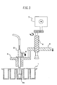
- a positioner includes a positioning member 9, a shaft 9a, a spring 9b, and a retainer 9c, is installed through a nozzle support jig 10, and can be moved vertically. Also, the section at which the nozzle support jig 10 is fastened to an arm 5 has an added movable part 11 so that when a reaction cuvette 1 and the positioning member 9 are guided toward each other, the nozzle support jig 10 can be moved slightly in a horizontal direction. A relationship in position between the positioning member 9 and a suction member 3 is the same as a positional relationship of the reaction cuvette 1 to its adjacent reaction cuvettes. The positioning member 9 when rinse water is not suctioned is positioned to be lower than the suction member 3.
- Fig. 6 shows a state of the rinse mechanism existing when rinse water is suctioned.
- the arm 5, the nozzle support jig 10, a rinse nozzle 2, and the suction member 3 move downward.
- the positioning member 9, the shaft 9a, the spring 9b, and the retainer 9c also descend, since the positioning member 9 is present at a position lower than that of the suction member 3, the positioning member 9 approaches the reaction cuvette 1 earlier.
- the positioning member 9A descends to a reaction cuvette position 1c or reaction cuvette position 1d adjacent to a reaction cuvette position 1b into which the suction member 3 is inserted.
- the positioning member 9A has a tapering tip, and a wide clearance is formed between the inner wall of the reaction cuvette 1 and the tip of the positioning member 9.
- the positioning member 9A is therefore adapted to easily enter the reaction cuvette 1 and adjust an inserting position of the suction member 3 to a correct position.
- the movable part 11 assists the nozzle support jig 10 in moving horizontally. Since the suction member 3 and the reaction cuvette 1 are not changed in shape or size, the suction member is thus reliably inserted into the reaction cuvette without deterioration of rinse liquid suction performance and without dimensional increases of the reaction cuvette or of the apparatus. Therefore, high reliability of the automatic analyzer can be achieved.
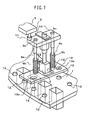
- the reaction cuvette 1 includes a convex (or concave) positioning guide pin (or tapered hole) 12.
- a positioning member 13 has a concave (or convex) tapered hole (or guide pin) 13a at a position matching a positional relationship of the positioning guide pin 12.
- Fig. 5 when rinse water is not suctioned, the positioning member 13 is positioned to be lower than the suction member 3.
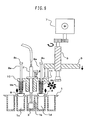
- Fig. 8 shows a state of the rinse mechanism when rinse water is suctioned. In this state, as in the state of Fig. 2 , the arm 5, the nozzle support jig 10, the rinse nozzle 2, and the suction member 3 move downward.
- the positioning member 13 descends to the positioning guide pin 12 adjacent to the reaction cuvette position 1b into which the suction member 3 is inserted.
- the concave (or convex) tapered hole (or guide pin) 13a is inserted at the position matching the positional relationship of the convex (or concave) positioning guide pin 12 provided on the reaction cuvette 1.
- a wide clearance is formed between the positioning guide pin 12 and the concave (or convex) tapered hole 13a in the positioning member 13.
- the positioning member 13 can easily enter the reaction cuvette 1 and works together with the positioning pin 12 to adjust the inserting position of the suction member 3 to the correct position.
- the movable part 11 assists the nozzle support jig 10 in moving horizontally. Since the suction member 3 and the reaction cuvette 1 are not changed in shape or size, the suction member 3 is thus reliably inserted into the reaction cuvette 1 without deterioration of rinse liquid suction performance and without dimensional increases of the reaction cuvette 1 or of the apparatus. Therefore, high reliability of the automatic analyzer can be achieved.
Landscapes
- Health & Medical Sciences (AREA)
- Chemical & Material Sciences (AREA)
- Clinical Laboratory Science (AREA)
- Chemical Kinetics & Catalysis (AREA)
- Analytical Chemistry (AREA)
- Life Sciences & Earth Sciences (AREA)
- Physics & Mathematics (AREA)
- Biochemistry (AREA)
- General Health & Medical Sciences (AREA)
- General Physics & Mathematics (AREA)
- Immunology (AREA)
- Pathology (AREA)
- Automatic Analysis And Handling Materials Therefor (AREA)
- Cleaning By Liquid Or Steam (AREA)
Abstract
Description
- The present invention relates generally to automatic analyzers for analyzing biological samples such as blood and urine, and more particularly, to an automatic analyzer with a rinse mechanism for rinsing a reaction cuvette.
- Automatic analyzers that conduct qualitative and/or quantitative analyses on a biological sample such as blood or urine cause the sample and a reagent to react in a reaction cuvette and analyze the constituents of the sample that are to be measured. After one measuring operation, the reaction cuvette formed of a material such as a plastic or glass is generally rinsed for reuse. The reaction cuvette, after being moved to a required rinsing position, is usually rinsed by suctioning the reaction liquid (the liquid left as a waste liquid after the measurement) with a nozzle, then repeating injection and suction of water, rinse water, or the like a required number of times, and finally suctioning the rinse water. In order to prevent the rinse water from remaining in the reaction cuvette after the rinsing thereof, a suction member formed to extend along the inner wall of the reaction cuvette is installed at the tip of a rinsing nozzle.
JP-A-10-062431 - As described in
JP-A-10-062431 - An object of the present invention is to provide a highly reliable automatic analyzer comprising a rinse mechanism adapted such that a suction member is reliably inserted into a reaction cuvette without deterioration of rinse liquid suction performance, without dimensional increases of the reaction cuvette or of the apparatus, and without being affected by stopping position accuracy of the reaction cuvette.
- In order to achieve the above object, the present invention has the following configuration:
- An automatic analyzer comprises a reaction cuvette for mixing a sample and a reagent, a reaction disk for setting up the reaction cuvette thereon and transferring the reaction cuvette to a rinsing position, a rinse nozzle that suctions rinse water in the reaction cuvette, a suction member connected to the rinse nozzle, and a shifter for moving the rinse nozzle; wherein the analyzer is further provided with a controller which, in accordance with the position of a positioning guide provided on the reaction cuvette, controls the shifter such that the rinse nozzle is inserted into the cuvette.
- A more specific example is shown below. In an automatic analyzer comprising at least a reaction cuvette for mixing a sample and a reagent; a reaction disk for setting up the reaction cuvette thereon and transferring the cuvette to a rinsing position; and a rinse mechanism comprising a rinse nozzle that suctions and discharges rinse water injected into the reaction cuvette, a suction member connected to a tip of the rinse nozzle, a nozzle support jig for supporting the rinse nozzle, a vertically moving arm fastened to the nozzle support jig, a shifter including a feed screw to move the arm vertically, and a motor, the nozzle support jig for installing the rinse liquid suction nozzle to which the suction member is connected includes a positioning member, which is present at a position lower than that of the suction member, constructed to be vertically movable, tapered at its tip, brought close to/inserted into an adjacent reaction cuvette earlier than the suction member during a downward movement of the rinse mechanism, and adapted to adjust an inserting position of the suction member to a correct position if the stopping position of the reaction cuvette deviates. Additionally, in order to achieve the above object, in the above automatic analyzer according to the present invention, the reaction cuvette includes a convex (or concave) positioning guide pin (or tapered hole), whereas the positioning member has a concave (or convex) tapered hole (or guide pin); wherein the positioning member is present at a position lower than that of the suction member, constructed to be vertically movable, and adapted to adjust an inserting position of the suction member to a correct position if, during a downward movement of the rinse mechanism, the convex (or concave) section of the reaction cuvette and the concave (or convex) section of the positioning member are brought close to/inserted into each other earlier than the suction member is inserted into the reaction cuvette and thus the stopping position of the reaction cuvette deviates.
- According to the present invention, a highly reliable automatic analyzer can be provided that allows a rinse water suction member to be reliably inserted into a reaction cuvette during rinsing thereof and adjusts an inserting position of the suction member to a correct position even if the stopping position of the reaction cuvette deviates.
-
-
Fig. 1 is a diagram showing a state in which rinse water is not suctioned in a rinse mechanism based on a conventional technique; -
Fig. 2 is a diagram showing a state in which rinse water is suctioned in the rinse mechanism ofFig. 1 ; -
Fig. 3 is a diagram showing a state in which rinse water is suctioned in the rinse mechanism ofFig. 1 that includes a suction member tapered at its tip; -
Fig. 4 is a diagram of a tapered entrance of a reaction cuvette; -
Fig. 5 is a diagram showing a state in which rinse water is not suctioned in a first embodiment of the present invention; -
Fig. 6 is a diagram showing a state in which rinse water is suctioned in the first embodiment of the present invention; -
Fig. 7 is a diagram showing a state in which rinse water is not suctioned in a second embodiment of the present invention; and -
Fig. 8 is a diagram showing a state in which rinse water is suctioned in the second embodiment of the present invention. - The object of providing a highly reliable automatic analyzer that comprises a rinse mechanism adapted so that a suction member is reliably inserted into a reaction cuvette without deterioration of rinse liquid suction performance and without dimensional increases of the reaction cuvette or of the apparatus was realized by adding a positioning member to the nozzle support jig of the rinse mechanism.
-
Figs. 1 and2 are schematic block diagrams of a conventional rinse mechanism. - Referring to
Fig. 1 , areaction cuvette 1 is installed on a reaction disk. The rinse mechanism includes elements such as arinse nozzle 2, asuction member 3 connected to a tip of therinse nozzle 2, anozzle support jig 4 for supporting therinse nozzle 2, anarm 5 fastened to thenozzle support jig 4, afeed screw 6 andmotor 7 for moving thearm 5 vertically, and acushioning spring 8 for therinse nozzle 2.Fig. 1 shows the state of the rinse mechanism and reaction cuvette existing when rinse water is not suctioned.Fig. 2 shows the state of the rinse mechanism and reaction cuvette existing when rinse water is suctioned. InFig. 2 , downward movement of thearm 5 via themotor 7 and thefeed screw 6 also moves downward thenozzle support jig 4 fastened to thearm 5. Thus, therinse nozzle 2 andsuction member 3 connected to thenozzle support jig 4 are also moved downward and inserted into thereaction cuvette 1 that has been moved to a required rinsing position to suction/discharge the rinse water present in thereaction cuvette 1. A clearance between thesuction member 3 and an inner wall of thereaction cuvette 1 is very small, so if a stopping position of thereaction cuvette 1 deviates for reasons such as integrated dimensional errors of constituent parts, contact of thesuction member 3 with the entrance of thereaction cuvette 1 is likely, which causes an alarm indicating an insertion failure and results in an operational stoppage of the automatic analyzer. To avoid contact between thesuction member 3 and thereaction cuvette 1, an inserting position of thesuction member 3 can be adjusted conceivably by providing the tip of the suction member with ataper 3a as shown inFig. 3 or by providing the entrance of thereaction cuvette 1 with ataper 1a as shown inFig. 4 . If thesuction member 3 is provided with thetaper 3a as shown inFig. 3 , however, the rinse liquid is liable to remain unsuctioned in the reaction cuvette since the clearance between the tapered section and the inner wall of the reaction cuvette will increase. If the entrance of thereaction cuvette 1 is provided with thetaper 1a as shown inFig. 4 , since the distance from the starting position of the taper to the ending position thereof needs to be at least about 0.5 mm, the reaction cuvette will be 2.5 to 3.5 mm wide, which is about 1.4 times as wide as in conventional techniques. This increase in the width of the reaction cuvette will increase the spaces between the reaction cuvette and its adjacent reaction cuvettes, hence necessarily increasing the size of the reaction disk on which to set up the cuvettes, and posing problems associated with miniaturization of both the cuvettes and the apparatus. - Accordingly, the operation of a first embodiment of the present invention for solving the above problems will be described using
Figs. 5 ,6 ,7 , and8 . - Referring to
Fig. 5 , a positioner includes apositioning member 9, ashaft 9a, aspring 9b, and aretainer 9c, is installed through anozzle support jig 10, and can be moved vertically. Also, the section at which thenozzle support jig 10 is fastened to anarm 5 has an addedmovable part 11 so that when areaction cuvette 1 and thepositioning member 9 are guided toward each other, thenozzle support jig 10 can be moved slightly in a horizontal direction. A relationship in position between thepositioning member 9 and asuction member 3 is the same as a positional relationship of thereaction cuvette 1 to its adjacent reaction cuvettes. Thepositioning member 9 when rinse water is not suctioned is positioned to be lower than thesuction member 3.Fig. 6 shows a state of the rinse mechanism existing when rinse water is suctioned. In this state, as in the state ofFig. 2 , thearm 5, thenozzle support jig 10, arinse nozzle 2, and thesuction member 3 move downward. At this time, although thepositioning member 9, theshaft 9a, thespring 9b, and theretainer 9c also descend, since thepositioning member 9 is present at a position lower than that of thesuction member 3, thepositioning member 9 approaches thereaction cuvette 1 earlier. The positioning member 9A descends to areaction cuvette position 1c orreaction cuvette position 1d adjacent to areaction cuvette position 1b into which thesuction member 3 is inserted. The positioning member 9A has a tapering tip, and a wide clearance is formed between the inner wall of thereaction cuvette 1 and the tip of thepositioning member 9. The positioning member 9A is therefore adapted to easily enter thereaction cuvette 1 and adjust an inserting position of thesuction member 3 to a correct position. At this time, themovable part 11 assists the nozzle support jig 10 in moving horizontally. Since thesuction member 3 and thereaction cuvette 1 are not changed in shape or size, the suction member is thus reliably inserted into the reaction cuvette without deterioration of rinse liquid suction performance and without dimensional increases of the reaction cuvette or of the apparatus. Therefore, high reliability of the automatic analyzer can be achieved. -
Figs. 7 and8 illustrate another embodiment of the present invention. Referring toFig. 7 , thereaction cuvette 1 includes a convex (or concave) positioning guide pin (or tapered hole) 12. Also, apositioning member 13 has a concave (or convex) tapered hole (or guide pin) 13a at a position matching a positional relationship of thepositioning guide pin 12. As inFig. 5 , when rinse water is not suctioned, thepositioning member 13 is positioned to be lower than thesuction member 3.Fig. 8 shows a state of the rinse mechanism when rinse water is suctioned. In this state, as in the state ofFig. 2 , thearm 5, thenozzle support jig 10, the rinsenozzle 2, and thesuction member 3 move downward. At this time, although the positioningmember 13, theshaft 9a, thespring 9b, and theretainer 9c also descend, since the positioningmember 13 is present at a position lower than that of thesuction member 3, the positioningmember 13 approaches thereaction cuvette 1 earlier. The positioningmember 13 descends to thepositioning guide pin 12 adjacent to thereaction cuvette position 1b into which thesuction member 3 is inserted. At that time, the concave (or convex) tapered hole (or guide pin) 13a is inserted at the position matching the positional relationship of the convex (or concave)positioning guide pin 12 provided on thereaction cuvette 1. In addition, as in the above embodiment, a wide clearance is formed between thepositioning guide pin 12 and the concave (or convex)tapered hole 13a in the positioningmember 13. Hence, the positioningmember 13 can easily enter thereaction cuvette 1 and works together with thepositioning pin 12 to adjust the inserting position of thesuction member 3 to the correct position. At this time, themovable part 11 assists thenozzle support jig 10 in moving horizontally. Since thesuction member 3 and thereaction cuvette 1 are not changed in shape or size, thesuction member 3 is thus reliably inserted into thereaction cuvette 1 without deterioration of rinse liquid suction performance and without dimensional increases of thereaction cuvette 1 or of the apparatus. Therefore, high reliability of the automatic analyzer can be achieved.
Claims (4)
- An automatic analyzer comprising:a reaction cuvette for mixing a sample and a reagent;a reaction disk for setting up the reaction cuvette thereon, the disk being adapted to transfer the cuvette to a rinsing position;a rinse nozzle for suctioning rinse liquid from the reaction cuvette;a suction member connected to the rinse nozzle; anda shifter for moving the rinse nozzle;the analyzer further comprising control means which, in accordance with the position of a positioning guide provided on the reaction cuvette, controls the shifter such that the rinse nozzle is inserted into the reaction cuvette.
- The automatic analyzer according to claim 1,
wherein:the positioning guide is a guide pin or a tapered hole. - The automatic analyzer according to claim 2,
wherein:the shifter includes a tapered hole or guide pin that engages with the positioning guide. - The automatic analyzer according to claim 3,
wherein:the tapered hole or guide pin provided in the shifter is positioned below the suction member.
Applications Claiming Priority (1)
| Application Number | Priority Date | Filing Date | Title |
|---|---|---|---|
| JP2007221989A JP5028186B2 (en) | 2007-08-29 | 2007-08-29 | Automatic analyzer |
Publications (3)
| Publication Number | Publication Date |
|---|---|
| EP2030690A2 true EP2030690A2 (en) | 2009-03-04 |
| EP2030690A3 EP2030690A3 (en) | 2009-03-11 |
| EP2030690B1 EP2030690B1 (en) | 2011-08-17 |
Family
ID=39870543
Family Applications (1)
| Application Number | Title | Priority Date | Filing Date |
|---|---|---|---|
| EP08015226A Not-in-force EP2030690B1 (en) | 2007-08-29 | 2008-08-28 | Automatic analyzer |
Country Status (5)
| Country | Link |
|---|---|
| US (1) | US8182745B2 (en) |
| EP (1) | EP2030690B1 (en) |
| JP (1) | JP5028186B2 (en) |
| CN (1) | CN101377517B (en) |
| AT (1) | ATE520989T1 (en) |
Families Citing this family (10)
| Publication number | Priority date | Publication date | Assignee | Title |
|---|---|---|---|---|
| JP5514582B2 (en) * | 2010-02-24 | 2014-06-04 | 株式会社日立製作所 | Liquid suction device |
| JP6289106B2 (en) * | 2014-01-10 | 2018-03-07 | キヤノンメディカルシステムズ株式会社 | Clinical laboratory equipment |
| US10288633B2 (en) | 2015-06-26 | 2019-05-14 | Abbott Laboratories | Reaction vessel moving member for moving reaction vessels from a processing track to a rotating device in a diagnostic analyzer |
| US10379130B2 (en) | 2015-06-26 | 2019-08-13 | Abbott Laboratories | Reaction vessel exchanger device for a diagnostic analyzer |
| RU2617167C1 (en) * | 2015-11-27 | 2017-04-21 | Федеральное государственное автономное образовательное учреждение высшего образования "Национальный исследовательский Томский государственный университет" (ТГУ) | Installation for studying deposition of solid particles aggregate in liquid |
| EP3309542B1 (en) * | 2016-10-14 | 2019-03-27 | Roche Diagniostics GmbH | Test element analysis system for the analytical examination of a sample |
| US10603667B2 (en) | 2017-02-22 | 2020-03-31 | Hitachi High-Technologies Corporation | Automatic analysis device and cleaning mechanism in automatic analysis device |
| CN108982886B (en) * | 2017-06-05 | 2021-11-19 | 深圳迈瑞生物医疗电子股份有限公司 | Sample introduction structure of sample analyzer, sample analyzer and sampling method |
| CN112088311B (en) * | 2018-03-15 | 2024-11-26 | 株式会社日立高新技术 | Automatic analysis device |
| WO2023090446A1 (en) * | 2021-11-22 | 2023-05-25 | 国立大学法人東京大学 | Sample analyzer and sample analysis method |
Citations (1)
| Publication number | Priority date | Publication date | Assignee | Title |
|---|---|---|---|---|
| JPH1062431A (en) | 1996-08-21 | 1998-03-06 | Jeol Ltd | Washing device in automatic biochemical analyzer |
Family Cites Families (9)
| Publication number | Priority date | Publication date | Assignee | Title |
|---|---|---|---|---|
| FR2120300A5 (en) * | 1970-12-29 | 1972-08-18 | Hoffmann La Roche | |
| JPS5761559U (en) * | 1980-09-19 | 1982-04-12 | ||
| US4713218A (en) * | 1985-07-22 | 1987-12-15 | Sequoia-Turner Corporation | Tube trap apparatus |
| US4803050A (en) * | 1985-07-22 | 1989-02-07 | Sequoia-Turner Corporation | Method and apparatus for liquid addition and aspiration in automated immunoassay techniques |
| US4751052A (en) | 1985-07-22 | 1988-06-14 | Sequoia-Turner Corporation | Tube alignment apparatus |
| JPS646760A (en) * | 1987-06-27 | 1989-01-11 | Yasunobu Tsukioka | Washing apparatus for reaction vessel in inspecting apparatus of blood and the like |
| US5268103A (en) * | 1990-07-13 | 1993-12-07 | Isco, Inc. | Apparatus and method for supercritical fluid extraction |
| ID23862A (en) * | 1998-02-20 | 2000-05-25 | Scil Diagnotics Gmbh | ANALYSIS SYSTEM |
| US7300523B2 (en) * | 2003-07-18 | 2007-11-27 | Dade Behring Inc. | Method for selectively washing used reaction cuvettes in an automatic analyzer |
-
2007
- 2007-08-29 JP JP2007221989A patent/JP5028186B2/en not_active Expired - Fee Related
-
2008
- 2008-08-28 AT AT08015226T patent/ATE520989T1/en not_active IP Right Cessation
- 2008-08-28 US US12/200,443 patent/US8182745B2/en not_active Expired - Fee Related
- 2008-08-28 CN CN2008102144774A patent/CN101377517B/en active Active
- 2008-08-28 EP EP08015226A patent/EP2030690B1/en not_active Not-in-force
Patent Citations (1)
| Publication number | Priority date | Publication date | Assignee | Title |
|---|---|---|---|---|
| JPH1062431A (en) | 1996-08-21 | 1998-03-06 | Jeol Ltd | Washing device in automatic biochemical analyzer |
Also Published As
| Publication number | Publication date |
|---|---|
| CN101377517B (en) | 2013-02-06 |
| CN101377517A (en) | 2009-03-04 |
| JP2009053125A (en) | 2009-03-12 |
| ATE520989T1 (en) | 2011-09-15 |
| EP2030690B1 (en) | 2011-08-17 |
| US8182745B2 (en) | 2012-05-22 |
| JP5028186B2 (en) | 2012-09-19 |
| EP2030690A3 (en) | 2009-03-11 |
| US20090068063A1 (en) | 2009-03-12 |
Similar Documents
| Publication | Publication Date | Title |
|---|---|---|
| EP2030690B1 (en) | Automatic analyzer | |
| EP1767950B1 (en) | Method and apparatus for accurate positioning of a pipetting device | |
| US6238626B1 (en) | Automatic distribution apparatus and method of distribution | |
| US20120222773A1 (en) | Analyzer and position confirming method | |
| EP0825444B1 (en) | Washing device for automatic biochemical analyzer | |
| US4931402A (en) | Photometric analysis equipment | |
| US8679421B2 (en) | Dispensing device and analyzer | |
| EP3588097B1 (en) | Automatic analysis device and cleaning mechanism in automatic analysis device | |
| US20170176485A1 (en) | Sample analyzer | |
| EP0036566B1 (en) | Discrete type automated chemical analytic apparatus | |
| EP2031409A2 (en) | Automatic multi-purpose analyser | |
| CN108139416A (en) | Inspection frame conveying device and automatic analysis system | |
| CN108896777A (en) | biochemical analyzer | |
| WO2017043192A1 (en) | Automated analyzer | |
| CN112924706A (en) | Pipetting unit and pipetting method for closing liquid containers | |
| JP2783449B2 (en) | Analyzer line control system | |
| EP4317982A1 (en) | Automated analysis device | |
| JP7301764B2 (en) | automatic analyzer | |
| CN113049801A (en) | Immunoassay analyzer | |
| EP4528282A1 (en) | Pipette tip positioning with guiding frame | |
| JP2008241500A (en) | Microchip positioning member | |
| EP4617673A1 (en) | Automatic analyzer | |
| JPH0318150B2 (en) | ||
| EP0590730B1 (en) | Aspirator probes |
Legal Events
| Date | Code | Title | Description |
|---|---|---|---|
| PUAI | Public reference made under article 153(3) epc to a published international application that has entered the european phase |
Free format text: ORIGINAL CODE: 0009012 |
|
| PUAL | Search report despatched |
Free format text: ORIGINAL CODE: 0009013 |
|
| AK | Designated contracting states |
Kind code of ref document: A2 Designated state(s): AT BE BG CH CY CZ DE DK EE ES FI FR GB GR HR HU IE IS IT LI LT LU LV MC MT NL NO PL PT RO SE SI SK TR |
|
| AX | Request for extension of the european patent |
Extension state: AL BA MK RS |
|
| AK | Designated contracting states |
Kind code of ref document: A3 Designated state(s): AT BE BG CH CY CZ DE DK EE ES FI FR GB GR HR HU IE IS IT LI LT LU LV MC MT NL NO PL PT RO SE SI SK TR |
|
| AX | Request for extension of the european patent |
Extension state: AL BA MK RS |
|
| 17P | Request for examination filed |
Effective date: 20090910 |
|
| AKX | Designation fees paid |
Designated state(s): AT BE BG CH CY CZ DE DK EE ES FI FR GB GR HR HU IE IS IT LI LT LU LV MC MT NL NO PL PT RO SE SI SK TR |
|
| 17Q | First examination report despatched |
Effective date: 20100317 |
|
| RIC1 | Information provided on ipc code assigned before grant |
Ipc: G01N 35/00 20060101AFI20100809BHEP |
|
| GRAP | Despatch of communication of intention to grant a patent |
Free format text: ORIGINAL CODE: EPIDOSNIGR1 |
|
| GRAS | Grant fee paid |
Free format text: ORIGINAL CODE: EPIDOSNIGR3 |
|
| GRAA | (expected) grant |
Free format text: ORIGINAL CODE: 0009210 |
|
| AK | Designated contracting states |
Kind code of ref document: B1 Designated state(s): AT BE BG CH CY CZ DE DK EE ES FI FR GB GR HR HU IE IS IT LI LT LU LV MC MT NL NO PL PT RO SE SI SK TR |
|
| REG | Reference to a national code |
Ref country code: GB Ref legal event code: FG4D |
|
| REG | Reference to a national code |
Ref country code: CH Ref legal event code: EP |
|
| REG | Reference to a national code |
Ref country code: IE Ref legal event code: FG4D |
|
| REG | Reference to a national code |
Ref country code: DE Ref legal event code: R096 Ref document number: 602008008862 Country of ref document: DE Effective date: 20111027 |
|
| REG | Reference to a national code |
Ref country code: NL Ref legal event code: VDEP Effective date: 20110817 |
|
| PG25 | Lapsed in a contracting state [announced via postgrant information from national office to epo] |
Ref country code: MT Free format text: LAPSE BECAUSE OF FAILURE TO SUBMIT A TRANSLATION OF THE DESCRIPTION OR TO PAY THE FEE WITHIN THE PRESCRIBED TIME-LIMIT Effective date: 20110817 |
|
| LTIE | Lt: invalidation of european patent or patent extension |
Effective date: 20110817 |
|
| PG25 | Lapsed in a contracting state [announced via postgrant information from national office to epo] |
Ref country code: IS Free format text: LAPSE BECAUSE OF FAILURE TO SUBMIT A TRANSLATION OF THE DESCRIPTION OR TO PAY THE FEE WITHIN THE PRESCRIBED TIME-LIMIT Effective date: 20111217 Ref country code: LT Free format text: LAPSE BECAUSE OF FAILURE TO SUBMIT A TRANSLATION OF THE DESCRIPTION OR TO PAY THE FEE WITHIN THE PRESCRIBED TIME-LIMIT Effective date: 20110817 Ref country code: PT Free format text: LAPSE BECAUSE OF FAILURE TO SUBMIT A TRANSLATION OF THE DESCRIPTION OR TO PAY THE FEE WITHIN THE PRESCRIBED TIME-LIMIT Effective date: 20111219 Ref country code: NL Free format text: LAPSE BECAUSE OF FAILURE TO SUBMIT A TRANSLATION OF THE DESCRIPTION OR TO PAY THE FEE WITHIN THE PRESCRIBED TIME-LIMIT Effective date: 20110817 Ref country code: FI Free format text: LAPSE BECAUSE OF FAILURE TO SUBMIT A TRANSLATION OF THE DESCRIPTION OR TO PAY THE FEE WITHIN THE PRESCRIBED TIME-LIMIT Effective date: 20110817 Ref country code: SE Free format text: LAPSE BECAUSE OF FAILURE TO SUBMIT A TRANSLATION OF THE DESCRIPTION OR TO PAY THE FEE WITHIN THE PRESCRIBED TIME-LIMIT Effective date: 20110817 Ref country code: NO Free format text: LAPSE BECAUSE OF FAILURE TO SUBMIT A TRANSLATION OF THE DESCRIPTION OR TO PAY THE FEE WITHIN THE PRESCRIBED TIME-LIMIT Effective date: 20111117 |
|
| REG | Reference to a national code |
Ref country code: AT Ref legal event code: MK05 Ref document number: 520989 Country of ref document: AT Kind code of ref document: T Effective date: 20110817 |
|
| PG25 | Lapsed in a contracting state [announced via postgrant information from national office to epo] |
Ref country code: AT Free format text: LAPSE BECAUSE OF FAILURE TO SUBMIT A TRANSLATION OF THE DESCRIPTION OR TO PAY THE FEE WITHIN THE PRESCRIBED TIME-LIMIT Effective date: 20110817 Ref country code: LV Free format text: LAPSE BECAUSE OF FAILURE TO SUBMIT A TRANSLATION OF THE DESCRIPTION OR TO PAY THE FEE WITHIN THE PRESCRIBED TIME-LIMIT Effective date: 20110817 Ref country code: PL Free format text: LAPSE BECAUSE OF FAILURE TO SUBMIT A TRANSLATION OF THE DESCRIPTION OR TO PAY THE FEE WITHIN THE PRESCRIBED TIME-LIMIT Effective date: 20110817 Ref country code: SI Free format text: LAPSE BECAUSE OF FAILURE TO SUBMIT A TRANSLATION OF THE DESCRIPTION OR TO PAY THE FEE WITHIN THE PRESCRIBED TIME-LIMIT Effective date: 20110817 Ref country code: CY Free format text: LAPSE BECAUSE OF FAILURE TO SUBMIT A TRANSLATION OF THE DESCRIPTION OR TO PAY THE FEE WITHIN THE PRESCRIBED TIME-LIMIT Effective date: 20110817 Ref country code: GR Free format text: LAPSE BECAUSE OF FAILURE TO SUBMIT A TRANSLATION OF THE DESCRIPTION OR TO PAY THE FEE WITHIN THE PRESCRIBED TIME-LIMIT Effective date: 20111118 |
|
| PG25 | Lapsed in a contracting state [announced via postgrant information from national office to epo] |
Ref country code: BE Free format text: LAPSE BECAUSE OF FAILURE TO SUBMIT A TRANSLATION OF THE DESCRIPTION OR TO PAY THE FEE WITHIN THE PRESCRIBED TIME-LIMIT Effective date: 20110817 Ref country code: MC Free format text: LAPSE BECAUSE OF NON-PAYMENT OF DUE FEES Effective date: 20110831 |
|
| PG25 | Lapsed in a contracting state [announced via postgrant information from national office to epo] |
Ref country code: CZ Free format text: LAPSE BECAUSE OF FAILURE TO SUBMIT A TRANSLATION OF THE DESCRIPTION OR TO PAY THE FEE WITHIN THE PRESCRIBED TIME-LIMIT Effective date: 20110817 Ref country code: SK Free format text: LAPSE BECAUSE OF FAILURE TO SUBMIT A TRANSLATION OF THE DESCRIPTION OR TO PAY THE FEE WITHIN THE PRESCRIBED TIME-LIMIT Effective date: 20110817 |
|
| REG | Reference to a national code |
Ref country code: IE Ref legal event code: MM4A |
|
| PG25 | Lapsed in a contracting state [announced via postgrant information from national office to epo] |
Ref country code: IT Free format text: LAPSE BECAUSE OF FAILURE TO SUBMIT A TRANSLATION OF THE DESCRIPTION OR TO PAY THE FEE WITHIN THE PRESCRIBED TIME-LIMIT Effective date: 20110817 Ref country code: RO Free format text: LAPSE BECAUSE OF FAILURE TO SUBMIT A TRANSLATION OF THE DESCRIPTION OR TO PAY THE FEE WITHIN THE PRESCRIBED TIME-LIMIT Effective date: 20110817 Ref country code: EE Free format text: LAPSE BECAUSE OF FAILURE TO SUBMIT A TRANSLATION OF THE DESCRIPTION OR TO PAY THE FEE WITHIN THE PRESCRIBED TIME-LIMIT Effective date: 20110817 |
|
| PLBE | No opposition filed within time limit |
Free format text: ORIGINAL CODE: 0009261 |
|
| STAA | Information on the status of an ep patent application or granted ep patent |
Free format text: STATUS: NO OPPOSITION FILED WITHIN TIME LIMIT |
|
| PG25 | Lapsed in a contracting state [announced via postgrant information from national office to epo] |
Ref country code: DK Free format text: LAPSE BECAUSE OF FAILURE TO SUBMIT A TRANSLATION OF THE DESCRIPTION OR TO PAY THE FEE WITHIN THE PRESCRIBED TIME-LIMIT Effective date: 20110817 |
|
| 26N | No opposition filed |
Effective date: 20120521 |
|
| PG25 | Lapsed in a contracting state [announced via postgrant information from national office to epo] |
Ref country code: HR Free format text: LAPSE BECAUSE OF FAILURE TO SUBMIT A TRANSLATION OF THE DESCRIPTION OR TO PAY THE FEE WITHIN THE PRESCRIBED TIME-LIMIT Effective date: 20120201 Ref country code: IE Free format text: LAPSE BECAUSE OF NON-PAYMENT OF DUE FEES Effective date: 20110828 |
|
| REG | Reference to a national code |
Ref country code: DE Ref legal event code: R097 Ref document number: 602008008862 Country of ref document: DE Effective date: 20120521 |
|
| REG | Reference to a national code |
Ref country code: CH Ref legal event code: PL |
|
| GBPC | Gb: european patent ceased through non-payment of renewal fee |
Effective date: 20120828 |
|
| PG25 | Lapsed in a contracting state [announced via postgrant information from national office to epo] |
Ref country code: LI Free format text: LAPSE BECAUSE OF NON-PAYMENT OF DUE FEES Effective date: 20120831 Ref country code: CH Free format text: LAPSE BECAUSE OF NON-PAYMENT OF DUE FEES Effective date: 20120831 Ref country code: ES Free format text: LAPSE BECAUSE OF FAILURE TO SUBMIT A TRANSLATION OF THE DESCRIPTION OR TO PAY THE FEE WITHIN THE PRESCRIBED TIME-LIMIT Effective date: 20111128 |
|
| PG25 | Lapsed in a contracting state [announced via postgrant information from national office to epo] |
Ref country code: LU Free format text: LAPSE BECAUSE OF NON-PAYMENT OF DUE FEES Effective date: 20110828 |
|
| PG25 | Lapsed in a contracting state [announced via postgrant information from national office to epo] |
Ref country code: BG Free format text: LAPSE BECAUSE OF FAILURE TO SUBMIT A TRANSLATION OF THE DESCRIPTION OR TO PAY THE FEE WITHIN THE PRESCRIBED TIME-LIMIT Effective date: 20111117 |
|
| PG25 | Lapsed in a contracting state [announced via postgrant information from national office to epo] |
Ref country code: GB Free format text: LAPSE BECAUSE OF NON-PAYMENT OF DUE FEES Effective date: 20120828 |
|
| PG25 | Lapsed in a contracting state [announced via postgrant information from national office to epo] |
Ref country code: TR Free format text: LAPSE BECAUSE OF FAILURE TO SUBMIT A TRANSLATION OF THE DESCRIPTION OR TO PAY THE FEE WITHIN THE PRESCRIBED TIME-LIMIT Effective date: 20110817 |
|
| PG25 | Lapsed in a contracting state [announced via postgrant information from national office to epo] |
Ref country code: HU Free format text: LAPSE BECAUSE OF FAILURE TO SUBMIT A TRANSLATION OF THE DESCRIPTION OR TO PAY THE FEE WITHIN THE PRESCRIBED TIME-LIMIT Effective date: 20110817 |
|
| PG25 | Lapsed in a contracting state [announced via postgrant information from national office to epo] |
Ref country code: HR Free format text: LAPSE BECAUSE OF FAILURE TO SUBMIT A TRANSLATION OF THE DESCRIPTION OR TO PAY THE FEE WITHIN THE PRESCRIBED TIME-LIMIT Effective date: 20110817 |
|
| REG | Reference to a national code |
Ref country code: FR Ref legal event code: PLFP Year of fee payment: 9 |
|
| REG | Reference to a national code |
Ref country code: FR Ref legal event code: PLFP Year of fee payment: 10 |
|
| REG | Reference to a national code |
Ref country code: FR Ref legal event code: PLFP Year of fee payment: 11 |
|
| REG | Reference to a national code |
Ref country code: DE Ref legal event code: R082 Ref document number: 602008008862 Country of ref document: DE Representative=s name: STREHL SCHUEBEL-HOPF & PARTNER MBB PATENTANWAE, DE Ref country code: DE Ref legal event code: R081 Ref document number: 602008008862 Country of ref document: DE Owner name: HITACHI HIGH-TECH CORPORATION, JP Free format text: FORMER OWNER: HITACHI HIGH-TECHNOLOGIES CORPORATION, TOKYO, JP |
|
| PGFP | Annual fee paid to national office [announced via postgrant information from national office to epo] |
Ref country code: DE Payment date: 20200819 Year of fee payment: 13 Ref country code: FR Payment date: 20200715 Year of fee payment: 13 |
|
| REG | Reference to a national code |
Ref country code: DE Ref legal event code: R119 Ref document number: 602008008862 Country of ref document: DE |
|
| PG25 | Lapsed in a contracting state [announced via postgrant information from national office to epo] |
Ref country code: FR Free format text: LAPSE BECAUSE OF NON-PAYMENT OF DUE FEES Effective date: 20210831 Ref country code: DE Free format text: LAPSE BECAUSE OF NON-PAYMENT OF DUE FEES Effective date: 20220301 |