EP2030649A1 - Heart monitoring system - Google Patents
Heart monitoring system Download PDFInfo
- Publication number
- EP2030649A1 EP2030649A1 EP08161234A EP08161234A EP2030649A1 EP 2030649 A1 EP2030649 A1 EP 2030649A1 EP 08161234 A EP08161234 A EP 08161234A EP 08161234 A EP08161234 A EP 08161234A EP 2030649 A1 EP2030649 A1 EP 2030649A1
- Authority
- EP
- European Patent Office
- Prior art keywords
- data
- service center
- monitoring system
- trigger
- heart monitoring
- Prior art date
- Legal status (The legal status is an assumption and is not a legal conclusion. Google has not performed a legal analysis and makes no representation as to the accuracy of the status listed.)
- Granted
Links
- 238000012544 monitoring process Methods 0.000 title claims abstract description 22
- 230000002861 ventricular Effects 0.000 claims abstract description 39
- 230000000638 stimulation Effects 0.000 claims abstract description 23
- 238000011157 data evaluation Methods 0.000 claims abstract description 22
- 238000004891 communication Methods 0.000 claims abstract description 17
- 230000000694 effects Effects 0.000 claims abstract description 17
- 238000002847 impedance measurement Methods 0.000 claims abstract description 13
- 210000000115 thoracic cavity Anatomy 0.000 claims abstract description 9
- 208000009729 Ventricular Premature Complexes Diseases 0.000 claims abstract description 6
- 206010047289 Ventricular extrasystoles Diseases 0.000 claims abstract description 6
- 238000001514 detection method Methods 0.000 claims abstract description 6
- 239000007943 implant Substances 0.000 claims abstract description 5
- 230000000747 cardiac effect Effects 0.000 claims abstract description 4
- 230000005540 biological transmission Effects 0.000 claims abstract description 3
- 230000008859 change Effects 0.000 claims description 17
- 229940079593 drug Drugs 0.000 claims description 10
- 239000003814 drug Substances 0.000 claims description 10
- 230000029058 respiratory gaseous exchange Effects 0.000 claims description 10
- 238000002560 therapeutic procedure Methods 0.000 claims description 9
- 230000037213 diet Effects 0.000 claims description 7
- 235000005911 diet Nutrition 0.000 claims description 7
- 238000011156 evaluation Methods 0.000 claims description 7
- 239000003086 colorant Substances 0.000 claims description 6
- 230000003993 interaction Effects 0.000 claims description 6
- 230000000284 resting effect Effects 0.000 claims description 2
- 230000008602 contraction Effects 0.000 claims 1
- 230000005284 excitation Effects 0.000 claims 1
- 210000004165 myocardium Anatomy 0.000 claims 1
- 230000001746 atrial effect Effects 0.000 description 21
- 230000006870 function Effects 0.000 description 4
- ZZUFCTLCJUWOSV-UHFFFAOYSA-N furosemide Chemical compound C1=C(Cl)C(S(=O)(=O)N)=CC(C(O)=O)=C1NCC1=CC=CO1 ZZUFCTLCJUWOSV-UHFFFAOYSA-N 0.000 description 4
- 229940063711 lasix Drugs 0.000 description 4
- 238000005259 measurement Methods 0.000 description 4
- 210000005241 right ventricle Anatomy 0.000 description 4
- 230000035939 shock Effects 0.000 description 4
- 230000036772 blood pressure Effects 0.000 description 3
- 230000001276 controlling effect Effects 0.000 description 3
- 238000007405 data analysis Methods 0.000 description 3
- 238000010586 diagram Methods 0.000 description 3
- 230000004044 response Effects 0.000 description 3
- 238000005316 response function Methods 0.000 description 3
- 206010037423 Pulmonary oedema Diseases 0.000 description 2
- 230000009471 action Effects 0.000 description 2
- 239000008280 blood Substances 0.000 description 2
- 210000004369 blood Anatomy 0.000 description 2
- 210000002837 heart atrium Anatomy 0.000 description 2
- 210000005240 left ventricle Anatomy 0.000 description 2
- 238000012986 modification Methods 0.000 description 2
- 230000004048 modification Effects 0.000 description 2
- 230000037081 physical activity Effects 0.000 description 2
- 210000005245 right atrium Anatomy 0.000 description 2
- 230000004936 stimulating effect Effects 0.000 description 2
- 239000013598 vector Substances 0.000 description 2
- 230000009271 DNA damage immune response Effects 0.000 description 1
- 102100026827 Protein associated with UVRAG as autophagy enhancer Human genes 0.000 description 1
- 101710102978 Protein associated with UVRAG as autophagy enhancer Proteins 0.000 description 1
- RTAQQCXQSZGOHL-UHFFFAOYSA-N Titanium Chemical compound [Ti] RTAQQCXQSZGOHL-UHFFFAOYSA-N 0.000 description 1
- 241000081258 Vesper Species 0.000 description 1
- 230000003044 adaptive effect Effects 0.000 description 1
- 230000004075 alteration Effects 0.000 description 1
- 238000004458 analytical method Methods 0.000 description 1
- QVGXLLKOCUKJST-UHFFFAOYSA-N atomic oxygen Chemical compound [O] QVGXLLKOCUKJST-UHFFFAOYSA-N 0.000 description 1
- 238000013194 cardioversion Methods 0.000 description 1
- 239000004020 conductor Substances 0.000 description 1
- 210000003748 coronary sinus Anatomy 0.000 description 1
- 239000013078 crystal Substances 0.000 description 1
- 238000005516 engineering process Methods 0.000 description 1
- 230000000004 hemodynamic effect Effects 0.000 description 1
- 210000003205 muscle Anatomy 0.000 description 1
- 229910052760 oxygen Inorganic materials 0.000 description 1
- 239000001301 oxygen Substances 0.000 description 1
- 230000036279 refractory period Effects 0.000 description 1
- -1 respiration rate Substances 0.000 description 1
- 229920006395 saturated elastomer Polymers 0.000 description 1
- 229910052719 titanium Inorganic materials 0.000 description 1
- 239000010936 titanium Substances 0.000 description 1
- 230000001960 triggered effect Effects 0.000 description 1
- 238000009423 ventilation Methods 0.000 description 1
- 238000011179 visual inspection Methods 0.000 description 1
Images



Classifications
-
- A—HUMAN NECESSITIES
- A61—MEDICAL OR VETERINARY SCIENCE; HYGIENE
- A61N—ELECTROTHERAPY; MAGNETOTHERAPY; RADIATION THERAPY; ULTRASOUND THERAPY
- A61N1/00—Electrotherapy; Circuits therefor
- A61N1/18—Applying electric currents by contact electrodes
- A61N1/32—Applying electric currents by contact electrodes alternating or intermittent currents
- A61N1/36—Applying electric currents by contact electrodes alternating or intermittent currents for stimulation
- A61N1/362—Heart stimulators
- A61N1/3627—Heart stimulators for treating a mechanical deficiency of the heart, e.g. congestive heart failure or cardiomyopathy
-
- A—HUMAN NECESSITIES
- A61—MEDICAL OR VETERINARY SCIENCE; HYGIENE
- A61B—DIAGNOSIS; SURGERY; IDENTIFICATION
- A61B5/00—Measuring for diagnostic purposes; Identification of persons
- A61B5/0002—Remote monitoring of patients using telemetry, e.g. transmission of vital signals via a communication network
- A61B5/0031—Implanted circuitry
-
- A—HUMAN NECESSITIES
- A61—MEDICAL OR VETERINARY SCIENCE; HYGIENE
- A61B—DIAGNOSIS; SURGERY; IDENTIFICATION
- A61B5/00—Measuring for diagnostic purposes; Identification of persons
- A61B5/05—Detecting, measuring or recording for diagnosis by means of electric currents or magnetic fields; Measuring using microwaves or radio waves
- A61B5/053—Measuring electrical impedance or conductance of a portion of the body
- A61B5/0537—Measuring body composition by impedance, e.g. tissue hydration or fat content
-
- A—HUMAN NECESSITIES
- A61—MEDICAL OR VETERINARY SCIENCE; HYGIENE
- A61N—ELECTROTHERAPY; MAGNETOTHERAPY; RADIATION THERAPY; ULTRASOUND THERAPY
- A61N1/00—Electrotherapy; Circuits therefor
- A61N1/18—Applying electric currents by contact electrodes
- A61N1/32—Applying electric currents by contact electrodes alternating or intermittent currents
- A61N1/36—Applying electric currents by contact electrodes alternating or intermittent currents for stimulation
- A61N1/362—Heart stimulators
- A61N1/37—Monitoring; Protecting
- A61N1/3702—Physiological parameters
-
- A—HUMAN NECESSITIES
- A61—MEDICAL OR VETERINARY SCIENCE; HYGIENE
- A61N—ELECTROTHERAPY; MAGNETOTHERAPY; RADIATION THERAPY; ULTRASOUND THERAPY
- A61N1/00—Electrotherapy; Circuits therefor
- A61N1/18—Applying electric currents by contact electrodes
- A61N1/32—Applying electric currents by contact electrodes alternating or intermittent currents
- A61N1/36—Applying electric currents by contact electrodes alternating or intermittent currents for stimulation
- A61N1/372—Arrangements in connection with the implantation of stimulators
- A61N1/37211—Means for communicating with stimulators
- A61N1/37252—Details of algorithms or data aspects of communication system, e.g. handshaking, transmitting specific data or segmenting data
- A61N1/37258—Alerting the patient
-
- A—HUMAN NECESSITIES
- A61—MEDICAL OR VETERINARY SCIENCE; HYGIENE
- A61N—ELECTROTHERAPY; MAGNETOTHERAPY; RADIATION THERAPY; ULTRASOUND THERAPY
- A61N1/00—Electrotherapy; Circuits therefor
- A61N1/18—Applying electric currents by contact electrodes
- A61N1/32—Applying electric currents by contact electrodes alternating or intermittent currents
- A61N1/36—Applying electric currents by contact electrodes alternating or intermittent currents for stimulation
- A61N1/372—Arrangements in connection with the implantation of stimulators
- A61N1/37211—Means for communicating with stimulators
- A61N1/37252—Details of algorithms or data aspects of communication system, e.g. handshaking, transmitting specific data or segmenting data
- A61N1/37282—Details of algorithms or data aspects of communication system, e.g. handshaking, transmitting specific data or segmenting data characterised by communication with experts in remote locations using a network
-
- A—HUMAN NECESSITIES
- A61—MEDICAL OR VETERINARY SCIENCE; HYGIENE
- A61N—ELECTROTHERAPY; MAGNETOTHERAPY; RADIATION THERAPY; ULTRASOUND THERAPY
- A61N1/00—Electrotherapy; Circuits therefor
- A61N1/18—Applying electric currents by contact electrodes
- A61N1/32—Applying electric currents by contact electrodes alternating or intermittent currents
- A61N1/36—Applying electric currents by contact electrodes alternating or intermittent currents for stimulation
- A61N1/362—Heart stimulators
- A61N1/365—Heart stimulators controlled by a physiological parameter, e.g. heart potential
- A61N1/36514—Heart stimulators controlled by a physiological parameter, e.g. heart potential controlled by a physiological quantity other than heart potential, e.g. blood pressure
- A61N1/36521—Heart stimulators controlled by a physiological parameter, e.g. heart potential controlled by a physiological quantity other than heart potential, e.g. blood pressure the parameter being derived from measurement of an electrical impedance
-
- A—HUMAN NECESSITIES
- A61—MEDICAL OR VETERINARY SCIENCE; HYGIENE
- A61N—ELECTROTHERAPY; MAGNETOTHERAPY; RADIATION THERAPY; ULTRASOUND THERAPY
- A61N1/00—Electrotherapy; Circuits therefor
- A61N1/18—Applying electric currents by contact electrodes
- A61N1/32—Applying electric currents by contact electrodes alternating or intermittent currents
- A61N1/36—Applying electric currents by contact electrodes alternating or intermittent currents for stimulation
- A61N1/372—Arrangements in connection with the implantation of stimulators
- A61N1/37211—Means for communicating with stimulators
- A61N1/37252—Details of algorithms or data aspects of communication system, e.g. handshaking, transmitting specific data or segmenting data
- A61N1/37264—Changing the program; Upgrading firmware
Definitions
- the invention relates to a heart monitoring system comprising an implantable medical device, an external transceiver device and a service center.
- the implantable medical device preferably is an implantable pacemaker or an implantable cardioverter/defibrillator (ICD) or a combination of both (CRT-D).
- ICD implantable cardioverter/defibrillator
- Some patients having an implantable pacemaker or an implantable cardioverter/defibrillator eventually suffer from decompensation. Decompensation needs to be detected and to be treated.
- CRT patients are detected (e.g. with lung edema sensor (DC offset via impedance) or combination of additional parameters (HRV, breathing, HR), then the physician needs to react and change CRT therapy.
- lung edema sensor DC offset via impedance
- HRV breathing, HR
- US 6,512,949 discloses a device that changes CRT therapy or activates drug pump automatically. This keeps the physician out of the loop for feedback and therapy control.
- central service center as integral part of the problem solving.
- data of several indicators for CHF status are sent to the service center preferably once a day.
- the parameters that serve as indicators and that are to be transferred and monitored include:
- the service center stores the data. Furthermore, the service center provides trends of the data in one graph or more graphs to allow visual inspection of the trends, changes of trends, and the timely coincidence of changes in the trends.
- a user interface being connected to the service center or being part of the service center is adapted to allow the physician to set for each trend its own, patients customized trigger criteria.
- the trigger criteria may include offset versus baseline or slope (positive and negative) or others.
- the user interface is adapted so that the physician can set trigger combination and its timely coincidence to receive alarm (via e-mail or otherwise); e.g. only by increase of both impedance vectors by x% and decrease of activity level by y% and increase of breathing rate by z% the service center triggers a decompensation alarm: "alarm - potential decompensation”.
- the service center and the user interface are adapted to interact such that
- the collected data is transmitted daily to the service center to allow trends with the same time basis.
- the data evaluation module preferably is adapted to trend the data with one datapoint per day for each trend.
- the service center is adapted to indicate a decompensation via a user interface connected to the service center and to allow the physician to initiate therapy changes actively via several remote activities including:
- a feedback channel from an individual patient to the physician may be provided that allows for a feedback whether a therapy change was successful or not.
- FIG. 1 shows an implantable device system comprising an implantable medical device 10, an external transceiver device 80 and a central service center 90.
- the implantable medical device 10 is for example an implantable pacemaker or an implantable cardioverter/defibrillator or a combination of both.
- the implantable medical device 10 comprises an implant transceiver for wireless communication with the external transceiver device 80.
- the external transceiver device 80 comprises an external transceiver unit (not shown) for wireless communication with the implant transceiver unit and a data communication interface (also not shown) adapted to allow a data communication with the service center 90.
- the data communication interface preferably is adapted to use a public data communication line as a telephone landline connection or wireless connection via GPRS or SMS or bluetooth.
- the central service center 90 comprises or is connected to a user interface allowing a physician or a team of physicians to interact with the central service center.
- the user interface may comprise a display for displaying data to the physician 100 and some input device allowing the physician 100 to enter instructions or data into the central service center 90.
- the central service center 90 further comprises a central data base that is connected to said data communication interface (see figure 4 ) and a data evaluation module that is connected to the data base that is adapted to evaluate data stored and said data base.
- the implantable medical device is a three chamber biventricular pacemaker and cardioverter/defibrillator 10 that is connected to pacing/sensing leads placed in a heart 12 is illustrated.
- the preferred embodiment is to couple the disclosed technology with an implantable bi-ventricular defibrillator.
- the implantable medical device 10 is electrically coupled to heart 12 by way of leads 14, 16 and 30.
- Lead 14 is a right atrial electrode lead that has a pair of right atrial electrodes 22 and 24 that are in contact with the right atria 26 of the heart 12.
- Lead 16 is a right ventricular electrode lead that has a pair of ventricular stimulation and sensing electrodes 18 and 20 that are in contact with the right ventricle 28 of heart 12. Further, a ventricular defibrillation shock coil 38 and an atrial defibrillation shock coil 40 are arranged on lead 16.
- Electrodes 22 and 18 are tip electrodes at the very distal end of leads 14 and 16, respectively. Electrode 22 is a right atrial tip electrode RA Tip and electrode 18 is a right ventricular tip electrode. Electrodes 24 and 20 are ring electrodes in close proximity but electrically isolated from the respective tip electrodes 22 and 18. Electrode 24 forms a right atrial ring electrode RA Ring and electrode 20 forms a right ventricular ring electrode RV Ring. Atrial cardioversion shock coil 40 is a coil electrode providing a relatively large geometric area when compared to the stimulation electrodes 18, 20, 22 and 24.
- Lead 30 is a left ventricular electrode lead passing through the coronary sinus of heart 12 and having a left ventricular ring electrode LV RING 32 a left ventricular tip electrode LV TIP 34. Further, a left ventricular defibrillation shock coil 36 is arranged on lead 30.
- Implantable medical device 10 has a case 42 made from electrically conductive material such as titanium that can serve as a large surface electrode IMD CASE.
- the plurality of electrodes 18, 20, 22, 24, 32, 34, 36, 38 and 40 connected to implantable medical device 10 together with case 42 allow for a number of different electrode configurations for measuring intrathoracic and intracardiac impedance.
- the forcing function for intrathoracic impedance measurement preferably is sourced via the right ventricular or a left ventricular ring electrode and the current sink would be the implantable medical device's case.
- Measurement of the response function preferably is carried out between a right ventricular tip electrode and the implantable medical device's case or a left ventricular tip electrode and the implantable medical device's case.
- injecting a forcing function from a right ventricular ring electrode to a right ventricular tip electrode and measuring a response function between a left ventricular ring electrode and a left ventricular tip electrode is preferred.
- FIG 3 a simplified block diagram of an implantable medical device 10 is illustrated.
- leads 14 and 16 are connected to respective output/input terminals of pacemaker 10 as indicated in figure 2 and carry stimulating pulses to the tip electrodes 18 and 22 from an right atrial stimulation pulse generator RA-STIM in a right atrial sense / pace stage 56 and a right ventricular pulse generator RV-STIM in a right ventricular sense / pace stage 50, respectively.
- RA-STIM right atrial stimulation pulse generator
- RV-STIM right ventricular pulse generator
- electrical signals from the atrium are carried from the electrode pair 18 and 20, through the lead 14, to the input terminal of an right atrial channel sensing stage RA-SENS in 56; and electrical signals from the right ventricle are carried from the electrode pair 22 and 24, through the lead 16, to the input terminal of a right ventricular sensing stage RV-SENS in 50.
- Left ventricular stimulating pulses are carried to the ring electrode 32 and the tip electrode 34 from a left ventricular pulse generator LV-STIM in the left ventricular sense / pace stage 52.
- Controlling the implantable medical device 10 is a control unit CTRL 54 that is connected to sensing stages A-SENS and V-SENS and to stimulation pulse generators A-STIM and V-STIM.
- Control unit CTRL 54 receives the output signals from the atrial sensing stage A-SENS and from the ventricular sensing stage V-SENS.
- the output signals of sensing stages A-SENS and V-SENS are generated each time that a P-wave representing an intrinsic atrial event or an R-wave representing an intrinsic ventricular event, respectively, is sensed within the heart 12.
- An As-signal is generated, when the atrial sensing stage A-SENS detects a P-wave and a Vs-signal is generated, when the ventricular sensing stage V-SENS detects an R-wave.
- Control unit CTRL 54 also generates trigger signals that are sent to the atrial stimulation pulse generator A-STIM and the ventricular stimulation pulse generator V-STIM, respectively. These trigger signals are generated each time that a stimulation pulse is to be generated by the respective pulse generator A-STIM or V-STIM.
- the atrial trigger signal is referred to simply as the "A-pulse”
- the ventricular trigger signal is referred to as the "V-pulse”.
- the corresponding sensing stage, A-SENS and/or V-SENS is typically disabled by way of a blanking signal presented to these amplifiers from the control unit CTRL 54, respectively.
- This blanking action prevents the sensing stages A-SENS and V-SENS from becoming saturated from the relatively large stimulation pulses that are present at their input terminals during this time. This blanking action also helps prevent residual electrical signals present in the muscle tissue as a result of the pacer stimulation from being interpreted as P-waves or R-waves.
- Atrial sense events As recorded shortly after delivery of a ventricular stimulation pulses during a preset time interval called post ventricular atrial refractory period (PVARP) are generally recorded as atrial refractory sense event Ars but ignored.
- PVARP post ventricular atrial refractory period
- Control unit CTRL 54 comprises circuitry for timing ventricular and/or atrial stimulation pulses according to an adequate stimulation rate that can be adapted to a patient's hemodynamic need as pointed out below.
- the implantable medical device 10 includes a memory circuit MEM 56 that is coupled to the control unit CTRL 54 over a suitable data/address bus ADR.
- This memory circuit MEM 56 allows certain control parameters, used by the control unit CTRL 54 in control-ling the operation of the implantable medical device 10, to be programmable stored and modified, as required, in order to customize the implantable medical device's operation to suit the needs of a particular patient.
- Such data includes the basic timing intervals used during operation of the pacemaker 10 and AV delay values and hysteresis AV delay values in particular.
- data sensed during the operation of the implantable medical device 10 may be stored in the memory MEM 56 for later retrieval and analysis.
- a telemetry circuit TEL 58 is further included in the implantable medical device 10. This telemetry circuit TEL 58 is connected to the control unit CTRL 54 by way of a suitable command/data bus. Telemetry circuit TEL 58 allows for wireless data exchange between the implantable medical device 10 and some remote programming or analyzing device which can be part of a centralized service center serving multiple pacemakers.
- the implantable medical device 10 in figure 3 is referred to as a three chamber pacemaker/cardioverter/defibrillator because it interfaces with the right atrium 26, the right ventricle 28 and the left ventricle of the heart 12.
- Those portions of the pacemaker 10 that interface with the right atrium, e.g., the lead 14, the P-wave sensing stage A-SENSE, the atrial stimulation pulse generator A-STIM and corresponding portions of the control unit CTRL 54, are commonly referred to as the atrial channel.
- those portions of the pacemaker 10 that interface with the right ventricle 28, e.g., the lead 16, the R-wave sensing stage V-SENSE, the ventricular stimulation pulse generator V-STIM, and corresponding portions of the control unit CTRL 54, are commonly referred to as the ventricular channel.
- the pacemaker 10 further includes a physiological sensor ACT 60 that is connected to the control unit CTRL 54 of the pacemaker 10. While this sensor ACT 60 is illustrated in figure 2 as being included within the pacemaker 10, it is to be understood that the sensor may also be external to the implantable medical device 10, yet still be implanted within or carried by the patient.
- a common type of sensor is an accelerometer, such as a piezoelectric crystal, mounted to the case of the pacemaker.
- physiologic sensors such as sensors that sense the oxygen content of blood, respiration rate, blood pH, intra-cardiac impedance changes, and the like.
- the type of sensor used is not critical to the present invention. Any sensor capable of sensing some physiological parameter relatable to physical activity of a patient can be used. Such sensors are commonly used with "rate-responsive" pacemakers in order to adjust the rate of the pacemaker in a manner that tracks the physiological needs of the patient.
- the output of sensor 48 represents an activity level.
- control unit 54 is able to assign each intrinsic heart rate to an activity thus enabling collection of intrinsic heart rate value for a patient's state of rest and a patient's state of exercise separately.
- the control unit CTRL 54 is adapted to determine an adequate heart rate or stimulation rate in any manner known as such.
- an impedance determination unit 70 is provided.
- Impedance determination unit 70 comprises a constant current source 72 that is connected or can be connected to electrodes for intracorporeal placement as shown in figure 2 .
- a constant current source 72 that is connected or can be connected to electrodes for intracorporeal placement as shown in figure 2 .
- some means of switching is provided between the constant current source 72 and the electrode terminals of the implantable medical device 10.
- the switch is not shown in figure 3 . Rather, particular impedance measurement configurations are shown as examples.
- a impedance measuring unit 74 for measuring a voltage corresponding to a current fed through a body by said constant current source is provided and can be connected to a number of electrodes although a switch for switching between these configurations is not shown in figure 3 .
- constant current source 72 a constant voltage source can be provided to generate the forcing function. Then, the measuring unit will be adapted to measure a current strength of a current fed through a body by said constant voltage source.
- Both, constant current source 72 and impedance measurement unit 74, are connected to an impedance value determination unit 76 that is adapted to determine an impedance value for each measuring current pulse delivered by the constant current source 72.
- an impedance measuring control and evaluation unit 78 is provided, that is connected to said impedance measurement unit and that is adapted to evaluate a sequence of consecutive impedance values determined by said impedance measurement unit.
- Impedance measuring control and evaluation unit 78 comprises a signal generator module (not shown) to construct the intra-cardiac impedance or conductance signal reflecting the time course of the impedance measurement unit's output signal and its derivative,
- Impedance measuring control and evaluation unit 78 further comprises a filter module (not shown) to filter the intra-cardiac impedance signal.
- Impedance measuring control and evaluation unit 78 comprises is connected to memory 56 and to telemetry unit 58 to allow for storing of impedance data and further evaluation by an external service center.
- control unit 54 Via intracardiac impedance measurement, control unit 54 is able to determine a stroke volume. From the stroke volume and the intrinsic heart rate the control unit calculates the cardiac output by multiplying the stroke volume and the heart rate.
- Via intrathoracic impedance measurement control unit 54 is able to determine a tidal volume and a ventilation rate (breathing rate) in a manner generally known to the skilled person.
- control unit 54 collects data representing:
- Figure 4 shows the central service center 90 comprising a data communication interface 92 for communicating with the external transceiver device 80.
- a central data base 94 for storing data representing measurements performed by the implantable medical device 10 and the external transceiver device 80.
- the central data base 94 is connected to a data evaluation module 96 that is adapted to evaluate data stored in said data base. The evaluation includes data trending of stored data.
- a user interface 98 Connected to the data analysis module is a user interface 98 for displaying data generated by the data analysis module 96 to a user allowing a user to enter instructions or data for controlling the data analysis module 96.
- the central service center receives data relating to
- the user interface 98 is adapted to allow the physician to set for each trend its own, patients customized trigger criteria.
- the trigger criteria may include offset versus baseline or slope (positive and negative) or others.
- the user interface 98 is adapted so that the physician can set trigger combination and its timely coincidence to receive an alarm triggered by the data evaluation module 96 when the trigger criteria are met and the data evaluation module generates a decompensation indicator signal. Then the service center 90 generates a decompensation alarm message that is transmitted to a physician via e-mail or otherwise. E.g. only by increase of both impedance vectors by x% and decrease of activity level by y% and increase of breathing rate by z% the service center triggers a decompensation alarm: "alarm - potential decompensation".
- the service center and the user interface are adapted to interact such that
- the data evaluation module trends the data with one datapoint per day for each trend.
- the data evaluation module and the user interface and their interaction are adapted to allow
- the data evaluation module and the user interface are further adapted to generate
- the service center 90 indicates a decompensation via the user interface 98 and allows the physician to initiate therapy changes actively via several remote activities including:
- a feedback channel (not shown) from an individual patient to the physician is provided that allows for a feedback whether a therapy change was successful or not.
Landscapes
- Health & Medical Sciences (AREA)
- Life Sciences & Earth Sciences (AREA)
- Engineering & Computer Science (AREA)
- Veterinary Medicine (AREA)
- Public Health (AREA)
- General Health & Medical Sciences (AREA)
- Biomedical Technology (AREA)
- Animal Behavior & Ethology (AREA)
- Nuclear Medicine, Radiotherapy & Molecular Imaging (AREA)
- Radiology & Medical Imaging (AREA)
- Heart & Thoracic Surgery (AREA)
- Cardiology (AREA)
- Biophysics (AREA)
- Molecular Biology (AREA)
- Surgery (AREA)
- Physics & Mathematics (AREA)
- Pathology (AREA)
- Medical Informatics (AREA)
- Computer Networks & Wireless Communication (AREA)
- Hospice & Palliative Care (AREA)
- Physiology (AREA)
- Electrotherapy Devices (AREA)
- Measuring And Recording Apparatus For Diagnosis (AREA)
- Apparatus For Radiation Diagnosis (AREA)
- External Artificial Organs (AREA)
Abstract
Description
- The invention relates to a heart monitoring system comprising an implantable medical device, an external transceiver device and a service center.
- The implantable medical device preferably is an implantable pacemaker or an implantable cardioverter/defibrillator (ICD) or a combination of both (CRT-D).
- Some patients having an implantable pacemaker or an implantable cardioverter/defibrillator eventually suffer from decompensation. Decompensation needs to be detected and to be treated.
- The detection of decompensation of CRT patients with lung edema sensor (detection of offset of the DC-impedance versus baseline) lacks of specificity (personal reports from many physicians). Several patents exists which describes that combination of additional parameters (HRV, breathing, HR) with the DC impedance offset may increase specificity.
- If decompensation in CRT patients are detected (e.g. with lung edema sensor (DC offset via impedance) or combination of additional parameters (HRV, breathing, HR), then the physician needs to react and change CRT therapy.
-
US 6,512,949 discloses a device that changes CRT therapy or activates drug pump automatically. This keeps the physician out of the loop for feedback and therapy control. - It is an object of the invention to provide a heart monitoring system that allows an improved detection of and response to decompensation.
- According to one aspect of the invention it is proposed to use central service center as integral part of the problem solving. Instead of fixed threshold values/algorithms in the device the data of several indicators for CHF status are sent to the service center preferably once a day. The parameters that serve as indicators and that are to be transferred and monitored include:
- (1) DC thoracic impedance from lead combination 1 and its changes.
- (2) DC thoracic impedance from lead combination 2 and its changes.
- (3) heart rate variability and its changes
- (4) heart rate at rest
- (5) heart rate during exercise.
- (6) activity level
- (7) VES per h
- (8) breathing rate
- (9) tidal volume
- (10) weight
- (11) (12) parameters from at least another sensor (contractility of the heart, pressure, temperature)
- (13) diet
- The service center stores the data. Furthermore, the service center provides trends of the data in one graph or more graphs to allow visual inspection of the trends, changes of trends, and the timely coincidence of changes in the trends. A user interface being connected to the service center or being part of the service center is adapted to allow the physician to set for each trend its own, patients customized trigger criteria. The trigger criteria may include offset versus baseline or slope (positive and negative) or others.
- Preferably, the user interface is adapted so that the physician can set trigger combination and its timely coincidence to receive alarm (via e-mail or otherwise); e.g. only by increase of both impedance vectors by x% and decrease of activity level by y% and increase of breathing rate by z% the service center triggers a decompensation alarm: "alarm - potential decompensation".
- The service center and the user interface are adapted to interact such that
- the user receives a set of standard triggers/trigger combination by the service center that is stored in the service center
- the user can store its own trigger logic and apply it to other patients
- a supervisor can collect the data of trigger logic from all patients and all users (physicians) and generated there from an improved set standard trigger criteria
- Alternatively the following features may be provided:
- Additional data is collected from outside sensors
- Weight is determined via a scale which sends weight data to the service center
- blood pressure data is collected via manual or automatic measurements and the results are send to the service center
- Diet information data is determined via barcode in a refrigerator and is send to the service center
- Duration of daily exercise (treadmill reports duration/speed/activity level) are transmitted to the service center
- Preferably the collected data is transmitted daily to the service center to allow trends with the same time basis.
- The data evaluation module preferably is adapted to trend the data with one datapoint per day for each trend.
- Regarding embodiments of the data evaluation module and the user interface and their interaction it is further preferred that they are adapted to allow
- a user to be able to activate / deactivate trigger for each trend (absolute value, positive/negative slope, duration of increase, 30 day line (to compensate for biological variations), 7 day line )
- a user to be able to combine trigger to trigger logic comprising a combination of trigger criteria to be met
- definition of a timely coincidence of triggers ("within 2 days")
- a display of data wherein graph-lines changes colors for each trend separately if trigger is not reached ("green") versus trigger is reached ("red")
- a display of data wherein a graph background changes colors for times for which the trigger logic was giving alarm ("alarm background")
- Another aspect of the invention is concerned with a response to a decompensation once detected. According to this aspect of the invention the service center is adapted to indicate a decompensation via a user interface connected to the service center and to allow the physician to initiate therapy changes actively via several remote activities including:
- Change of CRT parameters (e.g. % LV pacing was seen to be insufficient, then AVD would be adapted) via remote programming via the user interface
- Change of diet via telephone call to the patients
- Change of medication (Lasix) via telephone call to the patients
- Change of medication (Lasix) via remote programming of a drug pump using the user interface of the service center.
- Further, a feedback channel from an individual patient to the physician may be provided that allows for a feedback whether a therapy change was successful or not.
- The above and other aspects, features and advantages of the present invention will be more apparent from the following more particular description thereof, presented in conjunction with the following drawings wherein:
- FIG.1
- is a schematic overview over a heart monitoring system comprising an implantable medical device, an external transceiver device and a service center.
- FIG.2
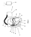
- shows a three chamber bi-ventricular implantable cardioverter/defibrillator (ICD).
- FIG. 3
- is a schematic diagram of the device modules of the ICD of
figure 3 . - FIG. 4
- is a schematic diagram of the service center.
- The following description is of the best mode presently contemplated for carrying out the invention. This description is not to be taken in a limiting sense, but is made merely for the purpose of describing the general principles of the invention. The scope of the invention should be determined with reference to the claims.
-
Figure 1 shows an implantable device system comprising an implantablemedical device 10, anexternal transceiver device 80 and acentral service center 90. The implantablemedical device 10 is for example an implantable pacemaker or an implantable cardioverter/defibrillator or a combination of both. The implantablemedical device 10 comprises an implant transceiver for wireless communication with theexternal transceiver device 80. Theexternal transceiver device 80 comprises an external transceiver unit (not shown) for wireless communication with the implant transceiver unit and a data communication interface (also not shown) adapted to allow a data communication with theservice center 90. The data communication interface preferably is adapted to use a public data communication line as a telephone landline connection or wireless connection via GPRS or SMS or bluetooth. - The
central service center 90 comprises or is connected to a user interface allowing a physician or a team of physicians to interact with the central service center. The user interface may comprise a display for displaying data to thephysician 100 and some input device allowing thephysician 100 to enter instructions or data into thecentral service center 90. Thecentral service center 90 further comprises a central data base that is connected to said data communication interface (seefigure 4 ) and a data evaluation module that is connected to the data base that is adapted to evaluate data stored and said data base. - In
figure 2 the implantable medical device is a three chamber biventricular pacemaker and cardioverter/defibrillator 10 that is connected to pacing/sensing leads placed in aheart 12 is illustrated. - As shown in
figure 2 , the preferred embodiment is to couple the disclosed technology with an implantable bi-ventricular defibrillator. - The implantable
medical device 10 is electrically coupled toheart 12 by way ofleads -
Lead 14 is a right atrial electrode lead that has a pair of rightatrial electrodes right atria 26 of theheart 12. -
Lead 16 is a right ventricular electrode lead that has a pair of ventricular stimulation andsensing electrodes right ventricle 28 ofheart 12. Further, a ventriculardefibrillation shock coil 38 and an atrialdefibrillation shock coil 40 are arranged onlead 16. -
Electrodes leads Electrode 22 is a right atrial tip electrode RA Tip andelectrode 18 is a right ventricular tip electrode.Electrodes respective tip electrodes Electrode 24 forms a right atrial ring electrode RA Ring andelectrode 20 forms a right ventricular ring electrode RV Ring. Atrialcardioversion shock coil 40 is a coil electrode providing a relatively large geometric area when compared to thestimulation electrodes -
Lead 30 is a left ventricular electrode lead passing through the coronary sinus ofheart 12 and having a left ventricular ring electrode LV RING 32 a left ventricular tipelectrode LV TIP 34. Further, a left ventriculardefibrillation shock coil 36 is arranged onlead 30. - Implantable
medical device 10 has acase 42 made from electrically conductive material such as titanium that can serve as a large surface electrode IMD CASE. - The plurality of
electrodes medical device 10 together withcase 42 allow for a number of different electrode configurations for measuring intrathoracic and intracardiac impedance. - The forcing function for intrathoracic impedance measurement preferably is sourced via the right ventricular or a left ventricular ring electrode and the current sink would be the implantable medical device's case. Measurement of the response function preferably is carried out between a right ventricular tip electrode and the implantable medical device's case or a left ventricular tip electrode and the implantable medical device's case.
- For intracardiac impedance measurements, injecting a forcing function from a right ventricular ring electrode to a right ventricular tip electrode and measuring a response function between a left ventricular ring electrode and a left ventricular tip electrode is preferred.
- Further possible electrode configurations for application of the forcing function and measurement of the response function become apparent from the following table:
Diagnostic Value Polarity Forcing contacts Response contacts Primary Tripolar RV Ring to Case RV Tip to Case Primary Tripolar LV Ring to Case LV Tip to Case Primary Bipolar RV Coil to Case RV Coil to Case Primary Bipolar LV Coil to Case LV Coil to Case Secondary Quadrapolar #1 LV Ring to RV Ring LV Tip to RV Tip Secondary Quadrapolar #2 RV Ring to RV Tip LV Ring to LV Tip Secondary Tripolar RV Ring to LV Ring RV Tip to LV Ring Secondary Tripolar RV Ring to LV Tip RV Tip to LV Tip Secondary Tripolar LV Ring to RV Ring LV Tip to RV Ring Secondary Tripolar LV Ring to RV Tip LV Tip to RV Tip Secondary Bipolar RV Ring to LV Ring RV Ring to LV Ring Secondary Bipolar RV Tip to LV Tip RV Tip to LV Tip Secondary Bipolar RV Ring to LV Tip RV Ring to LV Tip Secondary Bipolar RV Tip to LV Ring RV Tip to LV Ring - Referring to
figure 3 a simplified block diagram of an implantablemedical device 10 is illustrated. During operation of the pacemaker leads 14 and 16 are connected to respective output/input terminals ofpacemaker 10 as indicated infigure 2 and carry stimulating pulses to thetip electrodes pace stage 56 and a right ventricular pulse generator RV-STIM in a right ventricular sense /pace stage 50, respectively. Further, electrical signals from the atrium are carried from theelectrode pair lead 14, to the input terminal of an right atrial channel sensing stage RA-SENS in 56; and electrical signals from the right ventricle are carried from theelectrode pair lead 16, to the input terminal of a right ventricular sensing stage RV-SENS in 50.
Left ventricular stimulating pulses are carried to thering electrode 32 and thetip electrode 34 from a left ventricular pulse generator LV-STIM in the left ventricular sense /pace stage 52. Electrical signals from the left ventricle are carried from theelectrode pair medical device 10 is acontrol unit CTRL 54 that is connected to sensing stages A-SENS and V-SENS and to stimulation pulse generators A-STIM and V-STIM.Control unit CTRL 54 receives the output signals from the atrial sensing stage A-SENS and from the ventricular sensing stage V-SENS. The output signals of sensing stages A-SENS and V-SENS are generated each time that a P-wave representing an intrinsic atrial event or an R-wave representing an intrinsic ventricular event, respectively, is sensed within theheart 12. An As-signal is generated, when the atrial sensing stage A-SENS detects a P-wave and a Vs-signal is generated, when the ventricular sensing stage V-SENS detects an R-wave. - From a sequence of sensed R-
waves control unit 54 can determine an intrinsic heart rate that is used for decompensation detection. -
Control unit CTRL 54 also generates trigger signals that are sent to the atrial stimulation pulse generator A-STIM and the ventricular stimulation pulse generator V-STIM, respectively. These trigger signals are generated each time that a stimulation pulse is to be generated by the respective pulse generator A-STIM or V-STIM. The atrial trigger signal is referred to simply as the "A-pulse", and the ventricular trigger signal is referred to as the "V-pulse". During the time that either an atrial stimulation pulse or ventricular stimulation pulse is being delivered to the heart, the corresponding sensing stage, A-SENS and/or V-SENS, is typically disabled by way of a blanking signal presented to these amplifiers from thecontrol unit CTRL 54, respectively. This blanking action prevents the sensing stages A-SENS and V-SENS from becoming saturated from the relatively large stimulation pulses that are present at their input terminals during this time. This blanking action also helps prevent residual electrical signals present in the muscle tissue as a result of the pacer stimulation from being interpreted as P-waves or R-waves. - Furthermore, atrial sense events As recorded shortly after delivery of a ventricular stimulation pulses during a preset time interval called post ventricular atrial refractory period (PVARP) are generally recorded as atrial refractory sense event Ars but ignored.
-
Control unit CTRL 54 comprises circuitry for timing ventricular and/or atrial stimulation pulses according to an adequate stimulation rate that can be adapted to a patient's hemodynamic need as pointed out below. - Still referring to
figure 3 , the implantablemedical device 10 includes amemory circuit MEM 56 that is coupled to thecontrol unit CTRL 54 over a suitable data/address bus ADR. Thismemory circuit MEM 56 allows certain control parameters, used by thecontrol unit CTRL 54 in control-ling the operation of the implantablemedical device 10, to be programmable stored and modified, as required, in order to customize the implantable medical device's operation to suit the needs of a particular patient. Such data includes the basic timing intervals used during operation of thepacemaker 10 and AV delay values and hysteresis AV delay values in particular. - Further, data sensed during the operation of the implantable
medical device 10 may be stored in thememory MEM 56 for later retrieval and analysis. - A
telemetry circuit TEL 58 is further included in the implantablemedical device 10. Thistelemetry circuit TEL 58 is connected to thecontrol unit CTRL 54 by way of a suitable command/data bus.Telemetry circuit TEL 58 allows for wireless data exchange between the implantablemedical device 10 and some remote programming or analyzing device which can be part of a centralized service center serving multiple pacemakers. - The implantable
medical device 10 infigure 3 is referred to as a three chamber pacemaker/cardioverter/defibrillator because it interfaces with theright atrium 26, theright ventricle 28 and the left ventricle of theheart 12. Those portions of thepacemaker 10 that interface with the right atrium, e.g., thelead 14, the P-wave sensing stage A-SENSE, the atrial stimulation pulse generator A-STIM and corresponding portions of thecontrol unit CTRL 54, are commonly referred to as the atrial channel. Similarly, those portions of thepacemaker 10 that interface with theright ventricle 28, e.g., thelead 16, the R-wave sensing stage V-SENSE, the ventricular stimulation pulse generator V-STIM, and corresponding portions of thecontrol unit CTRL 54, are commonly referred to as the ventricular channel. - In order to be able to detect periods of physical activity of a patient indicating that the patient is awake and in order to allow rate adaptive pacing in a DDDR or a DDIR mode, the
pacemaker 10 further includes aphysiological sensor ACT 60 that is connected to thecontrol unit CTRL 54 of thepacemaker 10. While thissensor ACT 60 is illustrated infigure 2 as being included within thepacemaker 10, it is to be understood that the sensor may also be external to the implantablemedical device 10, yet still be implanted within or carried by the patient. A common type of sensor is an accelerometer, such as a piezoelectric crystal, mounted to the case of the pacemaker. Other types of physiologic sensors are also known, such as sensors that sense the oxygen content of blood, respiration rate, blood pH, intra-cardiac impedance changes, and the like. The type of sensor used is not critical to the present invention. Any sensor capable of sensing some physiological parameter relatable to physical activity of a patient can be used. Such sensors are commonly used with "rate-responsive" pacemakers in order to adjust the rate of the pacemaker in a manner that tracks the physiological needs of the patient. The output of sensor 48 represents an activity level. - By means of the output signal of
activity sensor 60 thecontrol unit 54 is able to assign each intrinsic heart rate to an activity thus enabling collection of intrinsic heart rate value for a patient's state of rest and a patient's state of exercise separately. - The
control unit CTRL 54 is adapted to determine an adequate heart rate or stimulation rate in any manner known as such. - For impedance measurement, an
impedance determination unit 70 is provided.Impedance determination unit 70 comprises a constantcurrent source 72 that is connected or can be connected to electrodes for intracorporeal placement as shown infigure 2 . In order to allow for a plurality of impedance measurement electrode configurations, preferably some means of switching is provided between the constantcurrent source 72 and the electrode terminals of the implantablemedical device 10. The switch is not shown infigure 3 . Rather, particular impedance measurement configurations are shown as examples. - Similarly, a
impedance measuring unit 74 for measuring a voltage corresponding to a current fed through a body by said constant current source is provided and can be connected to a number of electrodes although a switch for switching between these configurations is not shown infigure 3 . - As an alternative to constant current source 72 a constant voltage source can be provided to generate the forcing function. Then, the measuring unit will be adapted to measure a current strength of a current fed through a body by said constant voltage source.
- Both, constant
current source 72 andimpedance measurement unit 74, are connected to an impedancevalue determination unit 76 that is adapted to determine an impedance value for each measuring current pulse delivered by the constantcurrent source 72. - Further, an impedance measuring control and
evaluation unit 78 is provided, that is connected to said impedance measurement unit and that is adapted to evaluate a sequence of consecutive impedance values determined by said impedance measurement unit. Impedance measuring control andevaluation unit 78 comprises a signal generator module (not shown) to construct the intra-cardiac impedance or conductance signal reflecting the time course of the impedance measurement unit's output signal and its derivative, - Impedance measuring control and
evaluation unit 78 further comprises a filter module (not shown) to filter the intra-cardiac impedance signal. Impedance measuring control andevaluation unit 78 comprises is connected tomemory 56 and totelemetry unit 58 to allow for storing of impedance data and further evaluation by an external service center. - Via intracardiac impedance measurement,
control unit 54 is able to determine a stroke volume. From the stroke volume and the intrinsic heart rate the control unit calculates the cardiac output by multiplying the stroke volume and the heart rate. - Via intrathoracic impedance
measurement control unit 54 is able to determine a tidal volume and a ventilation rate (breathing rate) in a manner generally known to the skilled person. - Thus, the
control unit 54 collects data representing: - DC thoracic impedance from said first electrode combination
- DC thoracic impedance from said second electrode combination
- cardiac output
- heart rate variability
- heart rate at a resting state of a patient
- heart rate during exercise of a patient
- activity level of a patient
- ventricular extra systoles (VES) per time unit
- breathing rate
- tidal volume
-
Figure 4 shows thecentral service center 90 comprising adata communication interface 92 for communicating with theexternal transceiver device 80. Connected to thedata communication interface 92 is acentral data base 94 for storing data representing measurements performed by the implantablemedical device 10 and theexternal transceiver device 80. Thecentral data base 94 is connected to adata evaluation module 96 that is adapted to evaluate data stored in said data base. The evaluation includes data trending of stored data. - Connected to the data analysis module is a
user interface 98 for displaying data generated by thedata analysis module 96 to a user allowing a user to enter instructions or data for controlling thedata analysis module 96. - In addition to the data collected by the implantable
medical device 10, the central service center receives data relating to - weight
- blood pressure
- parameter from at least another sensor (contractility, pressure, temperature) and
- diet
- By the service center, the data is trended in one graph or more graphs to visually inspect trends and the timely coincidence of trends. The
user interface 98 is adapted to allow the physician to set for each trend its own, patients customized trigger criteria. The trigger criteria may include offset versus baseline or slope (positive and negative) or others. - Preferably, the
user interface 98 is adapted so that the physician can set trigger combination and its timely coincidence to receive an alarm triggered by thedata evaluation module 96 when the trigger criteria are met and the data evaluation module generates a decompensation indicator signal. Then theservice center 90 generates a decompensation alarm message that is transmitted to a physician via e-mail or otherwise. E.g. only by increase of both impedance vectors by x% and decrease of activity level by y% and increase of breathing rate by z% the service center triggers a decompensation alarm: "alarm - potential decompensation". - The service center and the user interface are adapted to interact such that
- the user receives a set of standard triggers/trigger combination by the service center that is stored in the service center
- the user can store its own trigger logic and apply it to other patients
- a supervisor can collect the data of trigger logic from all patients and all users (physicians) and generated there from an improved set standard trigger criteria
- Additional features of the system are:
- Additional data is collected from outside sensors
- Weight is determined via a scale which sends weight data to the service center
- blood pressure data is send to the service center
- Diet information data is determined via barcode in a refrigerator and is send to the service center
- Duration of daily exercise (treadmill reports duration/speed/activity level) are transmitted to the service center
- The data evaluation module trends the data with one datapoint per day for each trend.
- The data evaluation module and the user interface and their interaction are adapted to allow
- a user to be able to activate / deactivate trigger for each trend (absolute value, positive/negative slope, duration of increase, 30 day line (to compensate for biological variations), 7 day line )
- a user to be able to combine trigger to trigger logic comprising a combination of trigger criteria to be met
- a definition of a timely coincidence of triggers ("within 2 days")
- The data evaluation module and the user interface are further adapted to generate
- a display of data wherein graph-lines changes colors for each trend separately if trigger is not reached ("green") versus trigger is reached ("red")
- a display of data wherein a graph background changes colors for times for which the trigger logic was giving alarm ("alarm background")
- Once a potential decompensation is detected the
service center 90 indicates a decompensation via theuser interface 98 and allows the physician to initiate therapy changes actively via several remote activities including: - Change of CRT parameters (e.g. % LV pacing was seen to be insufficient, then AVD would be adapted) via remote programming via the user interface
- Change of diet via telephone call to the patients
- Change of medication (e.g. Lasix) via telephone call to the patients
- Change of medication (e.g. Lasix) via remote programming of a drug pump using the user interface of the service center.
- Further, a feedback channel (not shown) from an individual patient to the physician is provided that allows for a feedback whether a therapy change was successful or not.
- Although an exemplary embodiment of the present invention has been shown and described, it should be apparent to those of ordinary skill that a number of changes and modifications to the invention may be made without departing from the spirit and scope of the invention. This invention can readily be adapted to a number of different kinds of heart monitoring systems by following the present teachings. All such changes, modifications and alterations should therefore be recognized as falling within the scope of the present invention.
Claims (15)
- A heart monitoring system comprising an implantable medical device and a service center, whereinthe implantable medical device comprisesa stimulation pulse generator adapted to generate electric stimulation pulses and being connected or being connectable to at least a ventricular stimulation electrode for delivering electric stimulation pulses to at least said ventricle of the heart,a ventricular sensing stage connected or being connectable to an electrode for picking up electric potentials inside at least a ventricle of a heart, said sensing stage being adapted to sense an excitation or a contraction of ventricular myocardium,an activity sensor,an impedance determination unit comprising
a constant current source or a constant voltage source having current feed terminals that are connected or can be connected to electrodes for intracorporeal placement and that is adapted to generate sub-threshold measuring current pulses having a constant current strength or a constant voltage, respectively, for causing a current to be fed through a body via intracorpo-really placed electrodes,
a measuring unit for measuring a voltage corresponding to a current fed through a body by said constant current source or a current strength of a current fed through a body by said constant voltage source, respectively,
an impedance value determination unit that is connected to said constant current source or said constant voltage source and the measuring unit that is adapted to determine an impedance value for each measuring current pulse, and,
said impedance determination unit being adapted to perform an intrathoracic impedance measurement via a first and a second electrode combination wherein said second electrode configuration is different from said first electrode configuration,a control unit that is connected to said battery, said stimulation pulse generator, said sensing stage, said activity sensor and said impedance determination unit and that is adapted to collect data representing values of:- DC thoracic impedance from said first electrode combination- DC thoracic impedance from said second electrode combination- cardiac output- heart rate at a resting state of a patient- heart rate during exercise of a patient- activity level of a patient- ventricular extra systoles (VES) per time unit- breathing rate- tidal volumeandan implant transceiver unit communication with the service center andthe service center comprises another data communication interface adapted to allow at least an indirect data communication with said implantable medical device and is connected to a central data base and to a user interface,wherein said control unit that is adapted to initiate transmission of said collected data to said data center,
said service center further comprises a data evaluation module connected to said data base and adapted to evaluate data stored in said data base wherein said evaluation includes data trending of stored data and
said user interface and said data evaluation module are adapted to allow the physician to set for each data trend trigger criteria for the detection of decompensation and said data evaluation module is further adapted to generate a decompensation indicator signal whenever the trigger criteria are met by the trended data. - The heart monitoring system according to claim 1, wherein the heart monitoring system further comprises an external transceiver device said external transceiver device comprises an external transceiver unit for wireless communication with the implant transceiver unit and a data communication interface adapted to allow a data communication with the service center.
- The heart monitoring system according to claim 1 or 2, wherein said trigger criteria include an offset versus baseline or slope of he trended data as to trigger generation of said decompensation indicator signal whenever said offset is exceeded.
- The heart monitoring system according to one of the proceeding claims, wherein said data evaluation module is adapted to generate a decompensation indicator signal whenever a combination of trigger criteria are met by the trended data and/or whenever a pluratiy of trigger criteria are met in a preset timely coincidence.
- The heart monitoring system according to claim 4, wherein user interface is adapted so that a user can set trigger combination and/or its timely coincidence.
- The heart monitoring system according to claim 4, wherein said data evaluation module is adapted to generate a decompensation indicator signal if said change DC thoracic impedance from said first electrode combination and said DC thoracic impedance from said second electrode combination show a preset increase and activity level shows a preset decrease and said breathing rate shows a preset increase.
- The heart monitoring system according to one of the proceeding claims, wherein said service center is to transmit a decompensation alarm message adapted whenever the data evaluation module generates a decompensation indicator signal.
- The heart monitoring system according to one of the proceeding claims, wherein said implantable medical device is adapted to transmit the collected raw data daily to the service center.
- The heart monitoring system according to one of the proceeding claims, wherein said data evaluation module is adapted to trend the data with one datapoint per day for each trend.
- The heart monitoring system according to one of the proceeding claims, wherein said data evaluation module and said user interface and their interaction are designed to allow a user to be able to activate or deactivate trigger for each trend.
- The heart monitoring system according to one of the proceeding claims, wherein said data evaluation module and said user interface and their interaction are designed to allow a user to be able to combine trigger to trigger logic comprising a combination of trigger criteria to be met.
- The heart monitoring system according to one of the proceeding claims, wherein said data evaluation module and said user interface and their interaction are adapted to generate a display of data wherein graph-lines changes colors for each trend separately if trigger is not reached ("green") versus trigger is reached ("red").
- The heart monitoring system according to one of the proceeding claims, wherein said data evaluation module and said user interface and their interaction are adapted to generate a display of data wherein a graph background changes colors for times for which the trigger logic was giving alarm.
- The heart monitoring system according to one of the proceeding claims, wherein said service center is adapted to indicate a decompensation alarm via said user interface connected to the service center and to allow the physician to initiate therapy changes actively via several remote activities including:- Change of pacing parameters via remote programming via the user interface- Change of diet via telephone call to a patient- Change of medication via telephone call to a patient- Change of medication via remote programming of a drug pump using the user interface of the service center.
- The heart monitoring system according to one of the proceeding claims, further including a feedback channel from an individual patient to the user interface that allows for a feedback whether a therapy change was successful or not.
Applications Claiming Priority (1)
| Application Number | Priority Date | Filing Date | Title |
|---|---|---|---|
| US11/847,603 US7890160B2 (en) | 2007-08-30 | 2007-08-30 | Heart monitoring system |
Publications (2)
| Publication Number | Publication Date |
|---|---|
| EP2030649A1 true EP2030649A1 (en) | 2009-03-04 |
| EP2030649B1 EP2030649B1 (en) | 2009-10-28 |
Family
ID=40011407
Family Applications (1)
| Application Number | Title | Priority Date | Filing Date |
|---|---|---|---|
| EP08161234A Active EP2030649B1 (en) | 2007-08-30 | 2008-07-28 | Heart monitoring system |
Country Status (4)
| Country | Link |
|---|---|
| US (1) | US7890160B2 (en) |
| EP (1) | EP2030649B1 (en) |
| AT (1) | ATE446785T1 (en) |
| DE (1) | DE602008000246D1 (en) |
Cited By (2)
| Publication number | Priority date | Publication date | Assignee | Title |
|---|---|---|---|---|
| DE102009002399A1 (en) * | 2009-04-15 | 2010-10-21 | Biotronik Crm Patent Ag | Apparatus and method for processing physiological measurements |
| US20130184605A1 (en) * | 2012-01-13 | 2013-07-18 | Tak-Shing Ching | System and data processing device for bioimpedance analysis |
Families Citing this family (4)
| Publication number | Priority date | Publication date | Assignee | Title |
|---|---|---|---|---|
| US7771320B2 (en) | 2006-09-07 | 2010-08-10 | Nike, Inc. | Athletic performance sensing and/or tracking systems and methods |
| EP2383016B1 (en) | 2010-04-29 | 2017-08-23 | BIOTRONIK SE & Co. KG | Maintenance system for maintaining an energy accumulator arrangement |
| US9180242B2 (en) | 2012-05-17 | 2015-11-10 | Tandem Diabetes Care, Inc. | Methods and devices for multiple fluid transfer |
| EP2957321B1 (en) * | 2014-06-19 | 2018-10-10 | BIOTRONIK SE & Co. KG | Apparatus to optimize pacing parameters |
Citations (5)
| Publication number | Priority date | Publication date | Assignee | Title |
|---|---|---|---|---|
| WO1998033554A1 (en) * | 1997-01-31 | 1998-08-06 | Medtronic, Inc. | Implantable impedance measurement system |
| US6512949B1 (en) | 1999-07-12 | 2003-01-28 | Medtronic, Inc. | Implantable medical device for measuring time varying physiologic conditions especially edema and for responding thereto |
| US20060010090A1 (en) * | 2004-07-12 | 2006-01-12 | Marina Brockway | Expert system for patient medical information analysis |
| WO2007035696A1 (en) * | 2005-09-19 | 2007-03-29 | Cardiocom, Llc | Combining information from an implanted device and a patient monitoring apparatus |
| WO2007092212A2 (en) * | 2006-02-02 | 2007-08-16 | Cardiocom, Llc | Multiuser wellness parameter monitoring system |
Family Cites Families (1)
| Publication number | Priority date | Publication date | Assignee | Title |
|---|---|---|---|---|
| US7272442B2 (en) * | 2002-12-30 | 2007-09-18 | Cardiac Pacemakers, Inc. | Automatically configurable minute ventilation sensor |
-
2007
- 2007-08-30 US US11/847,603 patent/US7890160B2/en active Active
-
2008
- 2008-07-28 EP EP08161234A patent/EP2030649B1/en active Active
- 2008-07-28 DE DE602008000246T patent/DE602008000246D1/en active Active
- 2008-07-28 AT AT08161234T patent/ATE446785T1/en not_active IP Right Cessation
Patent Citations (5)
| Publication number | Priority date | Publication date | Assignee | Title |
|---|---|---|---|---|
| WO1998033554A1 (en) * | 1997-01-31 | 1998-08-06 | Medtronic, Inc. | Implantable impedance measurement system |
| US6512949B1 (en) | 1999-07-12 | 2003-01-28 | Medtronic, Inc. | Implantable medical device for measuring time varying physiologic conditions especially edema and for responding thereto |
| US20060010090A1 (en) * | 2004-07-12 | 2006-01-12 | Marina Brockway | Expert system for patient medical information analysis |
| WO2007035696A1 (en) * | 2005-09-19 | 2007-03-29 | Cardiocom, Llc | Combining information from an implanted device and a patient monitoring apparatus |
| WO2007092212A2 (en) * | 2006-02-02 | 2007-08-16 | Cardiocom, Llc | Multiuser wellness parameter monitoring system |
Cited By (3)
| Publication number | Priority date | Publication date | Assignee | Title |
|---|---|---|---|---|
| DE102009002399A1 (en) * | 2009-04-15 | 2010-10-21 | Biotronik Crm Patent Ag | Apparatus and method for processing physiological measurements |
| US8571641B2 (en) | 2009-04-15 | 2013-10-29 | Biotronik Crm Patent Ag | Apparatus and method for processing physiological measurement values |
| US20130184605A1 (en) * | 2012-01-13 | 2013-07-18 | Tak-Shing Ching | System and data processing device for bioimpedance analysis |
Also Published As
| Publication number | Publication date |
|---|---|
| DE602008000246D1 (en) | 2009-12-10 |
| ATE446785T1 (en) | 2009-11-15 |
| US7890160B2 (en) | 2011-02-15 |
| US20090062878A1 (en) | 2009-03-05 |
| EP2030649B1 (en) | 2009-10-28 |
Similar Documents
| Publication | Publication Date | Title |
|---|---|---|
| US8718751B2 (en) | Monitoring system for sleep disordered breathing | |
| EP1925337B1 (en) | Heart stimulator | |
| AU2009209397B2 (en) | Configurable intermittent pacing therapy | |
| US20060173498A1 (en) | Communication between an external defibrillator and an implantable medical device | |
| US8896462B2 (en) | Methods for low power communication in an implantable medical device | |
| US7676272B2 (en) | Implantable device system to collect parameter data for service center | |
| US7069078B2 (en) | Insulin-mediated glucose uptake monitor | |
| EP1331968B1 (en) | Method and system for measuring a source impedance of at least one cardiac electrical signal in a mammalian heart | |
| CN108348751A (en) | Cardiac stimulation based on multisensor | |
| US7996084B2 (en) | Implantable medical device with automatic ischemia threshold determination | |
| EP2030649B1 (en) | Heart monitoring system | |
| US8469897B2 (en) | Method and system for tracking quality of life in patients with angina | |
| US6636762B2 (en) | Method and system for monitoring heart failure using rate change dynamics | |
| US6650937B2 (en) | Method and system for gradual cardiac training using an implantable medical device | |
| US11642035B2 (en) | Heart rate recovery assessment | |
| EP1453571B1 (en) | Rate responsive pacing system with qt sensor based on intrinsic qt data | |
| US6695790B2 (en) | Method and system for determining kidney failure | |
| US20240042215A1 (en) | Method and device for controlling cardiac resynchronization therapy based on heart sounds | |
| US6564098B1 (en) | Method and system for increasing a pacer function of an implantable medical device disposed within a mammalian heart | |
| EP1987858B1 (en) | Follow-up support system for implantable medical devices | |
| US12431248B2 (en) | System and method for inter-device arrhythmia detection and confirmation | |
| US8812110B2 (en) | Implantable medical device | |
| US20080125823A1 (en) | Heart Stimulator | |
| US20210031035A1 (en) | System and method for treating and identifying an arrhythmia |
Legal Events
| Date | Code | Title | Description |
|---|---|---|---|
| PUAI | Public reference made under article 153(3) epc to a published international application that has entered the european phase |
Free format text: ORIGINAL CODE: 0009012 |
|
| 17P | Request for examination filed |
Effective date: 20081215 |
|
| AK | Designated contracting states |
Kind code of ref document: A1 Designated state(s): AT BE BG CH CY CZ DE DK EE ES FI FR GB GR HR HU IE IS IT LI LT LU LV MC MT NL NO PL PT RO SE SI SK TR |
|
| AX | Request for extension of the european patent |
Extension state: AL BA MK RS |
|
| GRAP | Despatch of communication of intention to grant a patent |
Free format text: ORIGINAL CODE: EPIDOSNIGR1 |
|
| GRAS | Grant fee paid |
Free format text: ORIGINAL CODE: EPIDOSNIGR3 |
|
| GRAA | (expected) grant |
Free format text: ORIGINAL CODE: 0009210 |
|
| AK | Designated contracting states |
Kind code of ref document: B1 Designated state(s): AT BE BG CH CY CZ DE DK EE ES FI FR GB GR HR HU IE IS IT LI LT LU LV MC MT NL NO PL PT RO SE SI SK TR |
|
| REG | Reference to a national code |
Ref country code: GB Ref legal event code: FG4D |
|
| REG | Reference to a national code |
Ref country code: CH Ref legal event code: EP |
|
| AKX | Designation fees paid |
Designated state(s): AT BE BG CH CY CZ DE DK EE ES FI FR GB GR HR HU IE IS IT LI LT LU LV MC MT NL NO PL PT RO SE SI SK TR |
|
| REG | Reference to a national code |
Ref country code: IE Ref legal event code: FG4D |
|
| REF | Corresponds to: |
Ref document number: 602008000246 Country of ref document: DE Date of ref document: 20091210 Kind code of ref document: P |
|
| REG | Reference to a national code |
Ref country code: SE Ref legal event code: TRGR |
|
| LTIE | Lt: invalidation of european patent or patent extension |
Effective date: 20091028 |
|
| NLV1 | Nl: lapsed or annulled due to failure to fulfill the requirements of art. 29p and 29m of the patents act | ||
| PG25 | Lapsed in a contracting state [announced via postgrant information from national office to epo] |
Ref country code: IS Free format text: LAPSE BECAUSE OF FAILURE TO SUBMIT A TRANSLATION OF THE DESCRIPTION OR TO PAY THE FEE WITHIN THE PRESCRIBED TIME-LIMIT Effective date: 20100228 Ref country code: ES Free format text: LAPSE BECAUSE OF FAILURE TO SUBMIT A TRANSLATION OF THE DESCRIPTION OR TO PAY THE FEE WITHIN THE PRESCRIBED TIME-LIMIT Effective date: 20100208 Ref country code: NO Free format text: LAPSE BECAUSE OF FAILURE TO SUBMIT A TRANSLATION OF THE DESCRIPTION OR TO PAY THE FEE WITHIN THE PRESCRIBED TIME-LIMIT Effective date: 20100128 Ref country code: FI Free format text: LAPSE BECAUSE OF FAILURE TO SUBMIT A TRANSLATION OF THE DESCRIPTION OR TO PAY THE FEE WITHIN THE PRESCRIBED TIME-LIMIT Effective date: 20091028 Ref country code: LT Free format text: LAPSE BECAUSE OF FAILURE TO SUBMIT A TRANSLATION OF THE DESCRIPTION OR TO PAY THE FEE WITHIN THE PRESCRIBED TIME-LIMIT Effective date: 20091028 |
|
| PG25 | Lapsed in a contracting state [announced via postgrant information from national office to epo] |
Ref country code: CY Free format text: LAPSE BECAUSE OF FAILURE TO SUBMIT A TRANSLATION OF THE DESCRIPTION OR TO PAY THE FEE WITHIN THE PRESCRIBED TIME-LIMIT Effective date: 20091028 Ref country code: SI Free format text: LAPSE BECAUSE OF FAILURE TO SUBMIT A TRANSLATION OF THE DESCRIPTION OR TO PAY THE FEE WITHIN THE PRESCRIBED TIME-LIMIT Effective date: 20091028 Ref country code: PL Free format text: LAPSE BECAUSE OF FAILURE TO SUBMIT A TRANSLATION OF THE DESCRIPTION OR TO PAY THE FEE WITHIN THE PRESCRIBED TIME-LIMIT Effective date: 20091028 Ref country code: HR Free format text: LAPSE BECAUSE OF FAILURE TO SUBMIT A TRANSLATION OF THE DESCRIPTION OR TO PAY THE FEE WITHIN THE PRESCRIBED TIME-LIMIT Effective date: 20091028 Ref country code: LV Free format text: LAPSE BECAUSE OF FAILURE TO SUBMIT A TRANSLATION OF THE DESCRIPTION OR TO PAY THE FEE WITHIN THE PRESCRIBED TIME-LIMIT Effective date: 20091028 |
|
| PG25 | Lapsed in a contracting state [announced via postgrant information from national office to epo] |
Ref country code: BE Free format text: LAPSE BECAUSE OF FAILURE TO SUBMIT A TRANSLATION OF THE DESCRIPTION OR TO PAY THE FEE WITHIN THE PRESCRIBED TIME-LIMIT Effective date: 20091028 Ref country code: AT Free format text: LAPSE BECAUSE OF FAILURE TO SUBMIT A TRANSLATION OF THE DESCRIPTION OR TO PAY THE FEE WITHIN THE PRESCRIBED TIME-LIMIT Effective date: 20091028 |
|
| PG25 | Lapsed in a contracting state [announced via postgrant information from national office to epo] |
Ref country code: EE Free format text: LAPSE BECAUSE OF FAILURE TO SUBMIT A TRANSLATION OF THE DESCRIPTION OR TO PAY THE FEE WITHIN THE PRESCRIBED TIME-LIMIT Effective date: 20091028 Ref country code: DK Free format text: LAPSE BECAUSE OF FAILURE TO SUBMIT A TRANSLATION OF THE DESCRIPTION OR TO PAY THE FEE WITHIN THE PRESCRIBED TIME-LIMIT Effective date: 20091028 Ref country code: BG Free format text: LAPSE BECAUSE OF FAILURE TO SUBMIT A TRANSLATION OF THE DESCRIPTION OR TO PAY THE FEE WITHIN THE PRESCRIBED TIME-LIMIT Effective date: 20100128 Ref country code: RO Free format text: LAPSE BECAUSE OF FAILURE TO SUBMIT A TRANSLATION OF THE DESCRIPTION OR TO PAY THE FEE WITHIN THE PRESCRIBED TIME-LIMIT Effective date: 20091028 |
|
| PG25 | Lapsed in a contracting state [announced via postgrant information from national office to epo] |
Ref country code: CZ Free format text: LAPSE BECAUSE OF FAILURE TO SUBMIT A TRANSLATION OF THE DESCRIPTION OR TO PAY THE FEE WITHIN THE PRESCRIBED TIME-LIMIT Effective date: 20091028 Ref country code: SK Free format text: LAPSE BECAUSE OF FAILURE TO SUBMIT A TRANSLATION OF THE DESCRIPTION OR TO PAY THE FEE WITHIN THE PRESCRIBED TIME-LIMIT Effective date: 20091028 |
|
| PLBE | No opposition filed within time limit |
Free format text: ORIGINAL CODE: 0009261 |
|
| STAA | Information on the status of an ep patent application or granted ep patent |
Free format text: STATUS: NO OPPOSITION FILED WITHIN TIME LIMIT |
|
| 26N | No opposition filed |
Effective date: 20100729 |
|
| PG25 | Lapsed in a contracting state [announced via postgrant information from national office to epo] |
Ref country code: GR Free format text: LAPSE BECAUSE OF FAILURE TO SUBMIT A TRANSLATION OF THE DESCRIPTION OR TO PAY THE FEE WITHIN THE PRESCRIBED TIME-LIMIT Effective date: 20100129 |
|
| PG25 | Lapsed in a contracting state [announced via postgrant information from national office to epo] |
Ref country code: MC Free format text: LAPSE BECAUSE OF NON-PAYMENT OF DUE FEES Effective date: 20100731 |
|
| PG25 | Lapsed in a contracting state [announced via postgrant information from national office to epo] |
Ref country code: IT Free format text: LAPSE BECAUSE OF FAILURE TO SUBMIT A TRANSLATION OF THE DESCRIPTION OR TO PAY THE FEE WITHIN THE PRESCRIBED TIME-LIMIT Effective date: 20091028 |
|
| PG25 | Lapsed in a contracting state [announced via postgrant information from national office to epo] |
Ref country code: MT Free format text: LAPSE BECAUSE OF FAILURE TO SUBMIT A TRANSLATION OF THE DESCRIPTION OR TO PAY THE FEE WITHIN THE PRESCRIBED TIME-LIMIT Effective date: 20091028 |
|
| PG25 | Lapsed in a contracting state [announced via postgrant information from national office to epo] |
Ref country code: NL Free format text: LAPSE BECAUSE OF FAILURE TO SUBMIT A TRANSLATION OF THE DESCRIPTION OR TO PAY THE FEE WITHIN THE PRESCRIBED TIME-LIMIT Effective date: 20091028 Ref country code: LU Free format text: LAPSE BECAUSE OF NON-PAYMENT OF DUE FEES Effective date: 20100728 Ref country code: HU Free format text: LAPSE BECAUSE OF FAILURE TO SUBMIT A TRANSLATION OF THE DESCRIPTION OR TO PAY THE FEE WITHIN THE PRESCRIBED TIME-LIMIT Effective date: 20100429 |
|
| PG25 | Lapsed in a contracting state [announced via postgrant information from national office to epo] |
Ref country code: TR Free format text: LAPSE BECAUSE OF FAILURE TO SUBMIT A TRANSLATION OF THE DESCRIPTION OR TO PAY THE FEE WITHIN THE PRESCRIBED TIME-LIMIT Effective date: 20091028 |
|
| PGFP | Annual fee paid to national office [announced via postgrant information from national office to epo] |
Ref country code: SE Payment date: 20120723 Year of fee payment: 5 Ref country code: GB Payment date: 20120723 Year of fee payment: 5 |
|
| PG25 | Lapsed in a contracting state [announced via postgrant information from national office to epo] |
Ref country code: PT Free format text: LAPSE BECAUSE OF NON-PAYMENT OF DUE FEES Effective date: 20091028 |
|
| REG | Reference to a national code |
Ref country code: SE Ref legal event code: EUG |
|
| GBPC | Gb: european patent ceased through non-payment of renewal fee |
Effective date: 20130728 |
|
| PG25 | Lapsed in a contracting state [announced via postgrant information from national office to epo] |
Ref country code: SE Free format text: LAPSE BECAUSE OF NON-PAYMENT OF DUE FEES Effective date: 20130729 Ref country code: GB Free format text: LAPSE BECAUSE OF NON-PAYMENT OF DUE FEES Effective date: 20130728 |
|
| REG | Reference to a national code |
Ref country code: DE Ref legal event code: R082 Ref document number: 602008000246 Country of ref document: DE Representative=s name: RANDOLL, SOEREN, DIPL.-CHEM. UNIV. DR. RER. NA, DE |
|
| REG | Reference to a national code |
Ref country code: FR Ref legal event code: PLFP Year of fee payment: 9 |
|
| REG | Reference to a national code |
Ref country code: FR Ref legal event code: PLFP Year of fee payment: 10 |
|
| REG | Reference to a national code |
Ref country code: DE Ref legal event code: R082 Ref document number: 602008000246 Country of ref document: DE Ref country code: DE Ref legal event code: R081 Ref document number: 602008000246 Country of ref document: DE Owner name: BIOTRONIK SE & CO. KG, DE Free format text: FORMER OWNER: BIOTRONIK CRM PATENT AG, BAAR, CH |
|
| REG | Reference to a national code |
Ref country code: FR Ref legal event code: PLFP Year of fee payment: 11 |
|
| REG | Reference to a national code |
Ref country code: FR Ref legal event code: TP Owner name: BIOTRONIK SE & CO. KG, DE Effective date: 20180907 |
|
| PGFP | Annual fee paid to national office [announced via postgrant information from national office to epo] |
Ref country code: IE Payment date: 20220720 Year of fee payment: 15 Ref country code: DE Payment date: 20220822 Year of fee payment: 15 |
|
| PGFP | Annual fee paid to national office [announced via postgrant information from national office to epo] |
Ref country code: FR Payment date: 20220726 Year of fee payment: 15 |
|
| PGFP | Annual fee paid to national office [announced via postgrant information from national office to epo] |
Ref country code: CH Payment date: 20220727 Year of fee payment: 15 |
|
| REG | Reference to a national code |
Ref country code: DE Ref legal event code: R119 Ref document number: 602008000246 Country of ref document: DE |
|
| REG | Reference to a national code |
Ref country code: CH Ref legal event code: PL |
|
| REG | Reference to a national code |
Ref country code: IE Ref legal event code: MM4A |
|
| PG25 | Lapsed in a contracting state [announced via postgrant information from national office to epo] |
Ref country code: DE Free format text: LAPSE BECAUSE OF NON-PAYMENT OF DUE FEES Effective date: 20240201 Ref country code: CH Free format text: LAPSE BECAUSE OF NON-PAYMENT OF DUE FEES Effective date: 20230731 |
|
| PG25 | Lapsed in a contracting state [announced via postgrant information from national office to epo] |
Ref country code: FR Free format text: LAPSE BECAUSE OF NON-PAYMENT OF DUE FEES Effective date: 20230731 |
|
| PG25 | Lapsed in a contracting state [announced via postgrant information from national office to epo] |
Ref country code: IE Free format text: LAPSE BECAUSE OF NON-PAYMENT OF DUE FEES Effective date: 20230728 |
|
| PG25 | Lapsed in a contracting state [announced via postgrant information from national office to epo] |
Ref country code: IE Free format text: LAPSE BECAUSE OF NON-PAYMENT OF DUE FEES Effective date: 20230728 |