EP2030489B1 - X-ray transparent bed and gurney extender for use with mobile computerized tomography (ct) imaging systems - Google Patents
X-ray transparent bed and gurney extender for use with mobile computerized tomography (ct) imaging systems Download PDFInfo
- Publication number
- EP2030489B1 EP2030489B1 EP07777022.0A EP07777022A EP2030489B1 EP 2030489 B1 EP2030489 B1 EP 2030489B1 EP 07777022 A EP07777022 A EP 07777022A EP 2030489 B1 EP2030489 B1 EP 2030489B1
- Authority
- EP
- European Patent Office
- Prior art keywords
- gurney
- bed
- extender
- mount
- patient
- Prior art date
- Legal status (The legal status is an assumption and is not a legal conclusion. Google has not performed a legal analysis and makes no representation as to the accuracy of the status listed.)
- Active
Links
Images






Classifications
-
- A—HUMAN NECESSITIES
- A61—MEDICAL OR VETERINARY SCIENCE; HYGIENE
- A61G—TRANSPORT, PERSONAL CONVEYANCES, OR ACCOMMODATION SPECIALLY ADAPTED FOR PATIENTS OR DISABLED PERSONS; OPERATING TABLES OR CHAIRS; CHAIRS FOR DENTISTRY; FUNERAL DEVICES
- A61G7/00—Beds specially adapted for nursing; Devices for lifting patients or disabled persons
- A61G7/05—Parts, details or accessories of beds
- A61G7/065—Rests specially adapted therefor
- A61G7/07—Rests specially adapted therefor for the head or torso, e.g. special back-rests
- A61G7/072—Rests specially adapted therefor for the head or torso, e.g. special back-rests for the head only
-
- A—HUMAN NECESSITIES
- A61—MEDICAL OR VETERINARY SCIENCE; HYGIENE
- A61B—DIAGNOSIS; SURGERY; IDENTIFICATION
- A61B6/00—Apparatus or devices for radiation diagnosis; Apparatus or devices for radiation diagnosis combined with radiation therapy equipment
- A61B6/02—Arrangements for diagnosis sequentially in different planes; Stereoscopic radiation diagnosis
- A61B6/03—Computed tomography [CT]
- A61B6/032—Transmission computed tomography [CT]
-
- A—HUMAN NECESSITIES
- A61—MEDICAL OR VETERINARY SCIENCE; HYGIENE
- A61B—DIAGNOSIS; SURGERY; IDENTIFICATION
- A61B6/00—Apparatus or devices for radiation diagnosis; Apparatus or devices for radiation diagnosis combined with radiation therapy equipment
- A61B6/04—Positioning of patients; Tiltable beds or the like
- A61B6/0407—Supports, e.g. tables or beds, for the body or parts of the body
- A61B6/0442—Supports, e.g. tables or beds, for the body or parts of the body made of non-metallic materials
-
- A—HUMAN NECESSITIES
- A61—MEDICAL OR VETERINARY SCIENCE; HYGIENE
- A61B—DIAGNOSIS; SURGERY; IDENTIFICATION
- A61B6/00—Apparatus or devices for radiation diagnosis; Apparatus or devices for radiation diagnosis combined with radiation therapy equipment
- A61B6/44—Constructional features of apparatus for radiation diagnosis
- A61B6/4405—Constructional features of apparatus for radiation diagnosis the apparatus being movable or portable, e.g. handheld or mounted on a trolley
-
- A—HUMAN NECESSITIES
- A61—MEDICAL OR VETERINARY SCIENCE; HYGIENE
- A61G—TRANSPORT, PERSONAL CONVEYANCES, OR ACCOMMODATION SPECIALLY ADAPTED FOR PATIENTS OR DISABLED PERSONS; OPERATING TABLES OR CHAIRS; CHAIRS FOR DENTISTRY; FUNERAL DEVICES
- A61G1/00—Stretchers
- A61G1/04—Parts, details or accessories, e.g. head-, foot-, or like rests specially adapted for stretchers
-
- A—HUMAN NECESSITIES
- A61—MEDICAL OR VETERINARY SCIENCE; HYGIENE
- A61G—TRANSPORT, PERSONAL CONVEYANCES, OR ACCOMMODATION SPECIALLY ADAPTED FOR PATIENTS OR DISABLED PERSONS; OPERATING TABLES OR CHAIRS; CHAIRS FOR DENTISTRY; FUNERAL DEVICES
- A61G2210/00—Devices for specific treatment or diagnosis
- A61G2210/50—Devices for specific treatment or diagnosis for radiography
-
- G—PHYSICS
- G01—MEASURING; TESTING
- G01N—INVESTIGATING OR ANALYSING MATERIALS BY DETERMINING THEIR CHEMICAL OR PHYSICAL PROPERTIES
- G01N2223/00—Investigating materials by wave or particle radiation
- G01N2223/40—Imaging
- G01N2223/419—Imaging computed tomograph
-
- G—PHYSICS
- G01—MEASURING; TESTING
- G01N—INVESTIGATING OR ANALYSING MATERIALS BY DETERMINING THEIR CHEMICAL OR PHYSICAL PROPERTIES
- G01N2223/00—Investigating materials by wave or particle radiation
- G01N2223/60—Specific applications or type of materials
- G01N2223/612—Specific applications or type of materials biological material
Definitions
- This invention relates to anatomical imaging systems in general, and more particularly to mobile Computerized Tomography (CT) imaging systems and X-ray transparent bed and gurney extenders for use with the same.
- CT Computerized Tomography
- Strokes are the third leading cause of death in the United States, causing approximately 177,000 deaths per year, and strokes are the number one cause of long-term disability in the United States, currently affecting nearly 5 million people. Strokes are caused by an abrupt interruption of the blood supply to the brain or spinal cord, thereby depriving the tissue of oxygen and resulting in tissue damage.
- Strokes typically occur in one of two forms: (i) hemorrhagic stokes, which occur with the rupture of a blood vessel; and (ii) ischemic strokes, which occur with the obstruction of a blood vessel.
- Rapid diagnosis is a key component of stroke treatment. This is because the treatment for an ischemic stroke may be contra-indicated for the treatment for a hemorrhagic stroke and, furthermore, the effectiveness of a particular treatment may be time-sensitive. More particularly, the current preferred treatment for an acute ischemic stroke, i.e., the administration of tPA to eliminate clots, is contra-indicated for a hemorrhagic stroke. Furthermore, the clinical data suggests that the medication used to treat ischemic strokes (i.e., tPA) is most effective if it is administered within 3 hours of the onset of the stroke.
- tPA medication used to treat ischemic strokes
- Imaging is generally necessary to properly diagnose (and hence properly treat) a stroke. More particularly, imaging is generally necessary to: (i) distinguish strokes from other medical conditions; (ii) distinguish between the different types of strokes (i.e., hemorrhagic or ischemic); and (iii) determine appropriate treatments (e.g., the administration of tPA in the case of an ischemic stroke).
- CT scanners generally operate by directing X-rays into the body from a variety of positions, detecting the X-rays passing through the body, and then processing the detected X-rays so as to build a computer model of the patient's anatomy. This computer model can then be visualized so as to provide images of the patient's anatomy. It has been found that such CT scanning (including non-enhanced CT scanning, CT angiography scanning and CT perfusion scanning) is able to provide substantially all of the information needed to effectively diagnose (and hence properly treat) a stroke.
- the CT machine is typically located in the hospital's radiology department and the patient is typically received in the hospital's emergency room, and the "round-trip" time between the emergency room and the radiology department can frequently involve substantial delays, even in the best of hospitals. As a result, the time spent in transporting the patient from the emergency room to the radiology department and then back again can consume critical time which can compromise proper treatment of the patient.
- the CereTom TM CT machine is particularly well suited for use in stroke applications. More particularly, the CereTom TM CT machine is a small, mobile CT machine which can be pre-positioned in the emergency room and moved to the patient so that the patient can be scanned at their current location, on their emergency room bed or gurney, thus effectively eliminating "round-trip" delays between the emergency room and radiology department and thereby dramatically reducing the time needed to properly diagnose the patient.
- the CereTom TM CT machine also has application in numerous other situations where patients may be located remote from the CT machine, e.g., other hospital departments such as Intensive Care Units (ICUs), nursing homes, rehabilitation centers, etc.
- ICUs Intensive Care Units
- rehabilitation centers etc.
- the CereTom TM CT machine is designed to be as small and mobile as possible, and since the CereTom TM CT machine is intended primarily for stroke applications and thus need only scan the head of the patient, it is configured so as to have a relatively small-diameter scan opening, i.e., a scan opening just large enough to receive the head of the patient. Furthermore, since the beds and gurneys typically found in emergency rooms are too large to fit within the scan opening of the CereTom TM CT machine, there is an urgent need for a narrow, X-ray transparent extender for selective attachment to the bed or gurney so as to support the patient's head during scanning, whereby the patient can be quickly and easily scanned while remaining on their bed or
- a bed and gurney extender for selective attachment to a standard hospital bed or gurney for supporting the head of a patient during scanning, comprising:
- a bed and gurney extender for selective attachment to a bed or gurney for supporting the head of a patient during scanning, comprising:
- an apparatus for use in scanning a patient on a bed or gurney comprising:
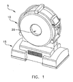
- CereTom TM CT machine 5 generally comprises a torus 10 which is supported by a base 15. A center opening 20 is formed in torus 10. Center opening 20 receives the patient anatomy which is to be scanned. Since CereTom TM CT machine 5 is designed to be as small and mobile as possible, and since CereTom TM CT machine 5 is intended primarily for stroke applications and thus need only scan the head of the patient, center opening 20 is configured to be just slightly larger than the head of the patient.
- torus 10 generally comprises an X-ray tube assembly 25, an X-ray detector assembly 30, and a rotating drum assembly 35.
- X-ray tube assembly 25 and X-ray detector assembly 30 are mounted to the rotating drum assembly 35 in diametrically-opposing relation, such that the X-ray beam 40 (generated by X-ray tube assembly 25 and detected by X-ray detector assembly 30) is passed through the patient anatomy disposed in center opening 20.
- X-ray tube assembly 25 and X-ray detector assembly 30 are mounted on the rotating drum assembly 35 so that they are rotated concentrically about center opening 20, the X-ray beam 40 will be passed through the patient's anatomy along a full range of radial positions, so as to enable the CereTom TM CT machine to create the desired computer model of the scanned anatomy.
- the various electronic hardware and software for controlling the operation of X-ray tube assembly 25, X-ray detector assembly 30, and rotating drum assembly 35, as well as for processing the acquired scan data so as to generate the desired computer model, are located in torus 10 and/or base 15.
- base 15 comprises a transport assembly 50 for moving CereTom TM CT machine 5 about relative to the patient. More particularly, as disclosed in the aforementioned U.S. Patent Application Serial No. 11/706,133 , which patent application is hereby incorporated herein by reference, transport assembly 50 comprises a gross movement mechanism 55 for moving CereTom TM CT machine 5 relatively quickly across room distances, and a fine movement mechanism 60 for moving CereTom TM CT machine 5 precisely, relative to the patient, during scanning. As discussed in detail in the aforementioned U.S. Patent Application Serial No. 11/706,133 , gross movement mechanism 55 preferably comprises a plurality of casters, and fine movement mechanism 60 preferably comprises a plurality of centipede belt drives. Hydraulic apparatus 65 permits either gross movement mechanism 55, or fine movement mechanism 60, to be engaged with the floor, whereby to facilitate appropriate movement of CereTom TM CT machine 5.
- Base 15 also includes other system components in addition to those discussed above, e.g., batteries 70 for powering various electrical components of CereTom TM CT machine 5, etc.
- CereTom TM CT machine 5 the various components of CereTom TM CT machine 5 are engineered so as to provide a relatively small, mobile and inexpensive CT machine.
- CereTom TM CT machine 5 is particularly well suited for use in stroke applications. More particularly, CereTom TM CT machine 5 is a small, mobile unit which can be pre-positioned in the emergency room and moved to the patient so that the patient can be scanned at their current location, thus eliminating delays due to patient transport and thereby dramatically reducing the time needed to properly diagnose the patient.
- the mobile CereTom TM CT machine 5 can be located in the emergency room of a hospital and, when a patient presents stroke symptoms, the patient can be immediately scanned in the emergency room so as to determine if the patient is experiencing a stroke and, if so, to determine the nature of the stroke (i.e., hemorrhagic or ischemic).
- CereTom TM CT machine 5 the patient can be scanned in the emergency room while remaining on their bed or gurney, without ever having to be moved from the emergency room to the radiology department and then back again, thereby eliminating the traditional scanning delays associated with conventional CT scanners and thus facilitating proper stroke treatment.
- the CereTom TM CT machine 5 also has application in numerous other situations where the patient is located remote from the CT machine, e.g., other hospital departments such as Intensive Care Units (ICUs), nursing homes, rehabilitation centers, etc.
- ICUs Intensive Care Units
- nursing homes e.g., nursing homes, rehabilitation centers, etc.
- CereTom TM CT machine 5 is designed to be as small and mobile as possible, and need only scan the head of the patient. As a result, CereTom TM CT machine 5 is configured so as to have a relatively small-diameter center scan opening 20 to receive the head of the patient. Since the hospital beds and gurneys typically found in emergency rooms are too large to fit within the scanning area of CereTom TM CT machine 5, the present invention provides a narrow, X-ray transparent extender for selective attachment to the bed or gurney so as to support the patient's head during scanning, whereby the patient can be quickly and easily scanned while remaining on their bed or gurney.
- bed and gurney extender 100 for selective attachment to a bed or gurney BG.
- bed or gurney BG may be a conventional bed or gurney of the type typically found in an emergency room, or it may be any other patient-supporting platform, e.g., an examination table, an operating table, a medical reclining chair, etc.
- Extender 100 generally comprises a support 105 for supporting the head of the patient during scanning, and an adapter 110 for selectively attaching support 105 to bed or gurney BG.
- support 105 generally comprises a shoulder section 115 for disposition on bed or gurney BG, under the shoulders of the patient, and a head section 120 for supporting the head of the patient.
- head section 120 is connected to shoulder section 115 by a neck section 125.
- At least head section 120 is formed out of an X-ray transparent material (e.g., carbon fiber, plastic, etc.), such that head section 120 can be in center opening 20 of CereTom TM CT machine 5 during scanning.
- shoulder section 115 and/or neck section 125 can also be formed out of an X-ray transparent material.
- At least one riser 130 extends out of the underside of shoulder section 115 for selective attachment to adapter 110. In one preferred form of the invention, two risers 130 are provided.
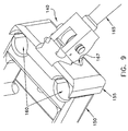
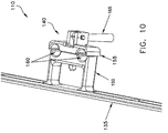
- Adapter 110 is shown in Figs. 4 and 7-10 .
- Adapter 110 generally comprises a bed and gurney mount 135 for selective attachment to the bed or gurney BG, and a riser clamp 140 for selectively securing the at least one riser 130 of support 105 to adapter 110.
- bed and gurney mount 135 is chosen according to the specific configuration of bed or gurney BG.
- bed or gurney BG comprises a pair of posts P upstanding from the frame F of bed or gurney BG
- bed and gurney mount 135 may comprise a pair of receptacles 145 for receiving posts P, whereby to secure bed and gurney mount 135 to the bed or gurney BG.
- bed and gurney mount 135, may be provided for bed and gurney mount 135, with the specific configuration of bed and gurney mount 135 being matched to the particular configuration of the bed or gurney BG with which the extender 100 is to be used.
- Riser clamp 140 comprises a fixed plate 150 and a movable plate 155 which together define at least one variably-sized opening 160 for selectively receiving and securing the at least one riser 130 of support 105.
- two variably-sized openings 160 are provided for receiving the two risers 130 of support 105.
- a handle 165 manipulates a cam mechanism for opening and closing riser clamp 140.
- handle 165 has a cam surface 166 which bears against plate surface 167 so as to selectively position movable plate 155 along shaft 168, whereby to open and close riser clamp 140.
- riser clamp 140 when riser clamp 140 is in its open position, risers 130 can be slidably received in openings 160; and when riser clamp 140 is in its closed position, risers 130 are secured to adapter 110, whereby to secure support 105 to bed or gurney BG.
- the apparatus may be used as follows.
- CereTom TM CT machine 5 which is pre-positioned in the emergency room
- extender 100 More particularly, CereTom TM CT machine 5 is raised on its gross movement mechanism 55, i.e., by actuating hydraulic actuators 65. CereTom TM CT machine 5 is then moved on its casters to the patient.
- Extender 100 is secured to the bed or gurney BG by securing adapter 110 to the bed or gurney BG, opening riser clamp 140 if it is not already open, moving risers 130 through openings 160 of riser clamp 140 until the extender's shoulder section 115 lies flat on the top surface of the bed or gurney BG (the patient may be lifted slightly to facilitate this), and then riser clamp 140 is closed, thereby securing support 105 to bed or gurney BG. Then the patient is moved as necessary so that the head of the patient lies on head section 120.
- CereTom TM CT machine 5 (which is still raised on its casters) is moved relative to the bed or gurney BG so that the center opening 20 of CereTom TM CT machine 5 is aligned with the patient.
- hydraulic apparatus 65 is activated so that CereTom TM CT machine 5 is supported on its fine movement mechanism 60 (i.e., the centipede belt drives).
- Scanning is then commenced, with fine movement mechanism 60 precision-advancing (or precision-retracting, or both precision-advancing and precision-retracting) CereTom TM CT machine 5 relative to the patient during scanning, with scanning being achieved while the patient remains on their bed or gurney.
- head section 120 (upon which the patient's head is supported) does not inhibit scanning, inasmuch as head section 120 is formed out of an X-ray transparent material.
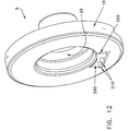
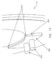
- CereTom TM CT machine 5 can be configured to facilitate storing extender 100 on torus 10 of CereTom TM CT machine 5. More particularly, a plate 200, including an undercut 205 and at least one post 210, is attached to the surface of torus 10. Preferably undercut 205 includes two or more beads 211 ( Fig. 13 ) which extend from plate 200 toward CereTom TM CT machine 5. Beads 211 may be made of an elastomer, or a plastic, or a metal. When extender 100 is to be stored on CereTom TM CT machine 5, risers 130 of support 105 are positioned in center opening 20 of CereTom TM CT machine 5 ( Fig.
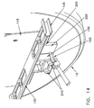
- adapter 110 is mounted on the at least one post 210 so as to press shoulder section 115 and head section 120 against torus 10 of CereTom TM CT machine 5 ( Figs. 11 and 14 ). This is done by opening riser clamp 140, mounting riser clamp 140 on the at least one post 210, and then closing riser clamp 140 so as to secure adapter 110 and hence extender 100 to CereTom TM CT machine 5.
- the at least one post 210 is preferably arranged so as to have the same configuration as that of the at least one riser 130 (i.e., preferably posts 210 and risers 130 are similar in diameter and, where multiple risers 130 are provided, similar in number and spacing).
- crank-operated riser clamp 300 generally comprises a screw 305 which has one end mounted in fixed plate 150 and another end passing through a bore 306 formed in movable plate 155.
- a crank 310 rides on the free end of screw 305.
- the inner portion 311 of crank 310 bears against an annular shoulder 312 formed in the outside face 313 of movable plate 155.
- a spring 315 biases movable plate 155 away from fixed plate 150; one end of spring 315 bears against fixed plate 150 and the other end of spring 315 bears against an annular surface 316 formed in the inside face 317 of movable plate 155.
- crank 310 can be used, in conjunction with spring 315, to move movable plate 155 toward and away from fixed plate 150 so as to close and open riser clamp 300.
- bed and gurney mount 135 many different bed and gurney configurations exist in the marketplace, and hence many different configurations may be provided for bed and gurney mount 135, with the specific configuration of bed and gurney mount 135 being matched to the particular configuration of the bed or gurney BG with which the extender 100 is to be used.
- Bed and gurney mount 135A is generally similar to the bed and gurney mount 135 previously discussed, in the sense that the unit mounts to the bed or gurney BG and supports the crank-operated riser clamp 300 (which in turn mounts support 105).
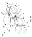
- the alternative bed and gurney mount 135A shown in Fig. 19 is mounted to bed or gurney BG by fitting posts 145A into corresponding holes H formed in the frame F of bed or gurney BG.
- a soft patient support PS may be added to bed and gurney support 105 so as to increase patient comfort.
- a patient support PS is shown covering head section 120 and neck section 125.
- Patient support PS may also cover shoulder section 115 if desired.
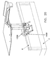
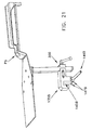
- FIGs. 20 and 21 show another alternative bed and gurney mount 135B.
- Bed and gurney mount 135B generally comprises a rectangular bottom slot 145B which receives a rectangular horizontal bar B of frame F. Due to the rectangular profiles of bottom slot 145B and bar B, bed and gurney mount 145B will be rotationally stable relative to horizontal bar B.
- Riser clamp 300 is formed integral with bed and gurney mount 135B.
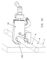
- the bed or gurney BG may comprise a frame F which includes a round rod R disposed adjacent to a vertical wall W.
- rotational stability must be provided if riser clamp 300 is mounted to the round rod R.
- a bed and gurney mount 135C having a slot 145C formed therein.
- a lever latch 146C including fingers 147C, releasably secures bed and gurney mount 135C to the round rod R.
- a pair of feet 148C bear against wall W of frame F so as to prevent clockwise rotation (when seen from the angle of view of Figs. 22 and 23 ) of bed and gurney mount 135C relative to round rod R.
- Riser clamp 300 is formed integral with bed and gurney mount 135C.
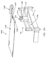
- extender 100D which generally comprises a shoulder section 115D and a head section 120D, joined by a neck section 125D.
- a horizontal rod 130D is used to connect extender 100 to adapter 110.
- adapter 110 generally comprises a bed and gurney mount 135D for selective attachment to the frame F of the bed or gurney, and a clamp 400 for clamping horizontal rod 130D in position.
- Clamp 400 generally comprises a fixed jaw 405 and a movable jaw 410.
- a screw 415 secures movable jaw to 410 fixed jaw 405.
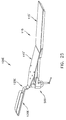
- support 105E which permits the patient's head to be aligned with the center opening 20 of CereTom TM CT machine 5.
- support 105E comprises a hinged shoulder section 115E for disposition under the shoulders of the patient, a head section 120E for supporting of the head of the patient, and a neck section 125E for connecting head section 120E to hinged shoulder section 115E.
- Hinged shoulder section 115E in turn a first shoulder section 115E' and a second shoulder section 115E".
- An elevator 500 is provided to raise or lower hinged shoulder section 115E" relative to hinged shoulder section 115E', whereby to permit the patient's head to be aligned with the center opening 20 of CereTom TM CT machine 5.
- Support 105E can be particularly useful when using an extender such as the extender 100D shown in Fig. 24 , inasmuch as extender 100D does not provide vertical adjustment of extender 100D relative to the bed or gurney BG. Elevator 500 of support 105E can provide this vertical adjustment.
- the present invention is not limited to use with a CereTom TM CT machine 5. It may be used with any type of CT machine where the CT machine is capable of moving its scan head relative to a fixed-position patient.
- the present invention is not limited to use with CT machines.
- the present invention may be used in connection with CT machines used for non-medical applications, e.g., with CT machines which are used to scan inanimate objects.
- the present invention may be used with non-CT-type scanning systems.
- the present invention may be used with a nuclear medicine diagnostic apparatus such as that disclosed in U.S. Patent No. 6,285,028 , issued 09/04/01 to Yamakawa for SEMICONDUCTOR RADIATION DETECTOR AND NUCLEAR MEDICINE DIAGNOSTIC APPARATUS, which patent is hereby incorporated herein by reference, wherein the diagnostic apparatus moves on rails disposed on either side of the patient.
- the present invention has application to any type of mobile imaging system in which the patient (or object) must be scanned on their bed or gurney (or other support).
Landscapes
- Health & Medical Sciences (AREA)
- Life Sciences & Earth Sciences (AREA)
- Engineering & Computer Science (AREA)
- Medical Informatics (AREA)
- Veterinary Medicine (AREA)
- Public Health (AREA)
- General Health & Medical Sciences (AREA)
- Animal Behavior & Ethology (AREA)
- Biophysics (AREA)
- Molecular Biology (AREA)
- Optics & Photonics (AREA)
- Pathology (AREA)
- Radiology & Medical Imaging (AREA)
- Biomedical Technology (AREA)
- Heart & Thoracic Surgery (AREA)
- Nuclear Medicine, Radiotherapy & Molecular Imaging (AREA)
- Surgery (AREA)
- High Energy & Nuclear Physics (AREA)
- Physics & Mathematics (AREA)
- Theoretical Computer Science (AREA)
- Pulmonology (AREA)
- Otolaryngology (AREA)
- Nursing (AREA)
- Apparatus For Radiation Diagnosis (AREA)
Description
- This invention relates to anatomical imaging systems in general, and more particularly to mobile Computerized Tomography (CT) imaging systems and X-ray transparent bed and gurney extenders for use with the same.
- Strokes are the third leading cause of death in the United States, causing approximately 177,000 deaths per year, and strokes are the number one cause of long-term disability in the United States, currently affecting nearly 5 million people. Strokes are caused by an abrupt interruption of the blood supply to the brain or spinal cord, thereby depriving the tissue of oxygen and resulting in tissue damage.
- Strokes typically occur in one of two forms: (i) hemorrhagic stokes, which occur with the rupture of a blood vessel; and (ii) ischemic strokes, which occur with the obstruction of a blood vessel.
- Rapid diagnosis is a key component of stroke treatment. This is because the treatment for an ischemic stroke may be contra-indicated for the treatment for a hemorrhagic stroke and, furthermore, the effectiveness of a particular treatment may be time-sensitive. More particularly, the current preferred treatment for an acute ischemic stroke, i.e., the administration of tPA to eliminate clots, is contra-indicated for a hemorrhagic stroke. Furthermore, the clinical data suggests that the medication used to treat ischemic strokes (i.e., tPA) is most effective if it is administered within 3 hours of the onset of the stroke. However, current diagnosis times, i.e., the time needed to identify that the patient is suffering from a stroke and to identify the hemorrhagic or ischemic nature of the stroke, frequently exceeds this 3 hour window. As a result, only a fraction of current ischemic stroke victims are timely treated with tPA.
- Imaging is generally necessary to properly diagnose (and hence properly treat) a stroke. More particularly, imaging is generally necessary to: (i) distinguish strokes from other medical conditions; (ii) distinguish between the different types of strokes (i.e., hemorrhagic or ischemic); and (iii) determine appropriate treatments (e.g., the administration of tPA in the case of an ischemic stroke).
- Computerized Tomography (CT) has emerged as the key imaging modality in the diagnosis of strokes. CT scanners generally operate by directing X-rays into the body from a variety of positions, detecting the X-rays passing through the body, and then processing the detected X-rays so as to build a computer model of the patient's anatomy. This computer model can then be visualized so as to provide images of the patient's anatomy. It has been found that such CT scanning (including non-enhanced CT scanning, CT angiography scanning and CT perfusion scanning) is able to provide substantially all of the information needed to effectively diagnose (and hence properly treat) a stroke.
- Unfortunately, in practice, the CT machine is typically located in the hospital's radiology department and the patient is typically received in the hospital's emergency room, and the "round-trip" time between the emergency room and the radiology department can frequently involve substantial delays, even in the best of hospitals. As a result, the time spent in transporting the patient from the emergency room to the radiology department and then back again can consume critical time which can compromise proper treatment of the patient.
- For this reason, as well as others, NeuroLogica Corporation of Danvers, Massachusetts has recently developed a mobile CT imaging system, i.e., the CereTom™ CT machine. The CereTom™ CT machine is particularly well suited for use in stroke applications. More particularly, the CereTom™ CT machine is a small, mobile CT machine which can be pre-positioned in the emergency room and moved to the patient so that the patient can be scanned at their current location, on their emergency room bed or gurney, thus effectively eliminating "round-trip" delays between the emergency room and radiology department and thereby dramatically reducing the time needed to properly diagnose the patient.
- The CereTom™ CT machine also has application in numerous other situations where patients may be located remote from the CT machine, e.g., other hospital departments such as Intensive Care Units (ICUs), nursing homes, rehabilitation centers, etc.
- Since the CereTom™ CT machine is designed to be as small and mobile as possible, and since the CereTom™ CT machine is intended primarily for stroke applications and thus need only scan the head of the patient, it is configured so as to have a relatively small-diameter scan opening, i.e., a scan opening just large enough to receive the head of the patient. Furthermore, since the beds and gurneys typically found in emergency rooms are too large to fit within the scan opening of the CereTom™ CT machine, there is an urgent need for a narrow, X-ray transparent extender for selective attachment to the bed or gurney so as to support the patient's head during scanning, whereby the patient can be quickly and easily scanned while remaining on their bed or
- Document
US4506872 A , andUS3631241 A , disclose a bed or gurney extender according to the preamble of claim 1. - These and other objects of the present disclosure are addressed by the provision and use of a narrow, X-ray transparent extender for selective attachment to a bed or gurney so as to support a patient's head during scanning, whereby a patient can be quickly and easily scanned while remaining on their bed or gurney.
- In accordance with the present disclosure, there is provided a bed and gurney extender for selective attachment to a standard hospital bed or gurney for supporting the head of a patient during scanning, comprising:
- a support for supporting the head of the patient during scanning, wherein at least a portion of the support is X-ray transparent; and
- an adapter for selectively attaching the support to the bed or gurney.
- Also disclosed is an apparatus for use in scanning a patient on a bed or gurney, comprising:
- a bed and gurney extender for selective attachment to a standard hospital bed or gurney for supporting the head of the patient during scanning, comprising:
- a support for supporting the head of the patient during scanning, wherein at least a portion of the support is X-ray transparent; and
- an adapter for selectively attaching the support to the bed or gurney.
- a bed and gurney extender for selective attachment to a standard hospital bed or gurney for supporting the head of the patient during scanning, comprising:
- There is also disclosed a method for scanning a patient, comprising:
- mounting an extender to the bed or gurney of the patient so as to present the head of the patient on an X-ray transparent support remote from the remainder of the bed or gurney;
- positioning the head of the patient adjacent to the scanning zone of a scanner; and
- moving the scanner precisely relative to the patient during scanning while the head of the patient remains disposed on the X-ray transparent support.
- There is also disclosed a bed and gurney extender for selective attachment to a bed or gurney for supporting the head of a patient during scanning, comprising:
- a support for supporting the head of the patient during scanning, wherein at least a portion of the support is transparent to the scanner; and
- an adapter for selectively attaching the support to the bed or gurney.
- There is also disclosed an apparatus for use in scanning a patient on a bed or gurney, comprising:
- a bed and gurney extender for selective attachment to a bed or gurney for supporting the head of the patient during scanning, comprising:
- a support for supporting the head of the patient during scanning, wherein at least a portion of the support is transparent to the scanner; and
- an adapter for selectively attaching the support to the bed or gurney.
- There is also disclosed a method for scanning a patient, comprising:
- mounting an extender to the bed or gurney of the patient so as to present the head of the patient on a support remote from the remainder of the bed or gurney, wherein the support is transparent to the scanner;
- positioning the head of the patient adjacent to the scanning zone of a scanner; and
- moving the scanner precisely relative to the patient during scanning while the head of the patient remains disposed on the scanner-transparent support.
- These and other objects and features of the present disclosure will be more fully disclosed or rendered obvious by the following detailed description of the preferred embodiments of the invention, which is to be considered together with the accompanying drawings wherein like numbers refer to like parts, and further wherein:
-
Figs. 1 and2 are schematic external views of a CereTom™ CT machine; -
Fig. 3 is a schematic internal view of the CereTom™ CT machine shown inFigs. 1 and2 ; -
Fig. 4 is a schematic view showing a bed and gurney extender formed in accordance with the present invention; -
Figs. 5 and6 are schematic views showing the support portion of the bed and gurney extender shown inFig. 4 ; -
Figs. 7-10 are schematic views showing the adapter portion of the bed and gurney extender shown inFig. 4 ; -
Figs. 11-14 are schematic views showing how the bed and gurney extender may be stored on a CereTom™ CT machine; and -
Figs. 15-18 are schematic views showing an alternative form of riser clamp which may be used in connection with the present invention; -
Fig. 19 is a schematic view showing an alternative form of the adapter portion of the bed and gurney extender; -
Figs. 20 and21 are schematic views showing still another alternative form of the adapter portion of the bed and gurney extender; -
Figs. 22 and23 are schematic views showing yet another form of the adapter portion of the bed and gurney extender; -
Fig. 24 is a schematic view showing another bed and gurney extender formed in accordance with the present invention; and -
Fig. 25 is a schematic view showing another support formed in accordance with the present invention. - Looking first at
Figs. 1 and2 , there is shown a CereTom™ CT machine 5. CereTom™ CT machine 5 generally comprises atorus 10 which is supported by abase 15. Acenter opening 20 is formed intorus 10.Center opening 20 receives the patient anatomy which is to be scanned. Since CereTom™ CT machine 5 is designed to be as small and mobile as possible, and since CereTom™ CT machine 5 is intended primarily for stroke applications and thus need only scan the head of the patient, center opening 20 is configured to be just slightly larger than the head of the patient. - Looking next at
Fig. 3 ,torus 10 generally comprises anX-ray tube assembly 25, anX-ray detector assembly 30, and arotating drum assembly 35.X-ray tube assembly 25 andX-ray detector assembly 30 are mounted to therotating drum assembly 35 in diametrically-opposing relation, such that the X-ray beam 40 (generated byX-ray tube assembly 25 and detected by X-ray detector assembly 30) is passed through the patient anatomy disposed incenter opening 20. Furthermore, sinceX-ray tube assembly 25 andX-ray detector assembly 30 are mounted on therotating drum assembly 35 so that they are rotated concentrically aboutcenter opening 20, theX-ray beam 40 will be passed through the patient's anatomy along a full range of radial positions, so as to enable the CereTom™ CT machine to create the desired computer model of the scanned anatomy. - The various electronic hardware and software for controlling the operation of
X-ray tube assembly 25,X-ray detector assembly 30, androtating drum assembly 35, as well as for processing the acquired scan data so as to generate the desired computer model, are located intorus 10 and/orbase 15. - Still looking now at
Fig. 3 ,base 15 comprises atransport assembly 50 for moving CereTom™ CT machine 5 about relative to the patient. More particularly, as disclosed in the aforementionedU.S. Patent Application Serial No. 11/706,133 , which patent application is hereby incorporated herein by reference,transport assembly 50 comprises agross movement mechanism 55 for moving CereTom™ CT machine 5 relatively quickly across room distances, and afine movement mechanism 60 for moving CereTom™ CT machine 5 precisely, relative to the patient, during scanning. As discussed in detail in the aforementionedU.S. Patent Application Serial No. 11/706,133 ,gross movement mechanism 55 preferably comprises a plurality of casters, andfine movement mechanism 60 preferably comprises a plurality of centipede belt drives.Hydraulic apparatus 65 permits eithergross movement mechanism 55, orfine movement mechanism 60, to be engaged with the floor, whereby to facilitate appropriate movement of CereTom™ CT machine 5. -
Base 15 also includes other system components in addition to those discussed above, e.g.,batteries 70 for powering various electrical components of CereTom™ CT machine 5, etc. - As noted above, the various components of CereTom™ CT machine 5 are engineered so as to provide a relatively small, mobile and inexpensive CT machine.
- CereTom™ CT machine 5 is particularly well suited for use in stroke applications. More particularly, CereTom™ CT machine 5 is a small, mobile unit which can be pre-positioned in the emergency room and moved to the patient so that the patient can be scanned at their current location, thus eliminating delays due to patient transport and thereby dramatically reducing the time needed to properly diagnose the patient.
- More particularly, the mobile CereTom™ CT machine 5 can be located in the emergency room of a hospital and, when a patient presents stroke symptoms, the patient can be immediately scanned in the emergency room so as to determine if the patient is experiencing a stroke and, if so, to determine the nature of the stroke (i.e., hemorrhagic or ischemic). This may be done quickly and easily by moving CereTom™ CT machine 5 across the emergency room to the patient's bed or gurney using the casters of
gross movement mechanism 55 and then, while the patient remains on their bed or gurney, scanning the patient by precision-advancing CereTom™ CT machine 5 relative to the patient using the centipede belt drives offine movement mechanism 60, so that the scanning zone of CereTom™ CT machine 5 is moved relative to the patient. Thus, with CereTom™ CT machine 5, the patient can be scanned in the emergency room while remaining on their bed or gurney, without ever having to be moved from the emergency room to the radiology department and then back again, thereby eliminating the traditional scanning delays associated with conventional CT scanners and thus facilitating proper stroke treatment. - As noted above, the CereTom™ CT machine 5 also has application in numerous other situations where the patient is located remote from the CT machine, e.g., other hospital departments such as Intensive Care Units (ICUs), nursing homes, rehabilitation centers, etc.
- As noted above, CereTom™ CT machine 5 is designed to be as small and mobile as possible, and need only scan the head of the patient. As a result, CereTom™ CT machine 5 is configured so as to have a relatively small-diameter center scan opening 20 to receive the head of the patient. Since the hospital beds and gurneys typically found in emergency rooms are too large to fit within the scanning area of CereTom™ CT machine 5, the present invention provides a narrow, X-ray transparent extender for selective attachment to the bed or gurney so as to support the patient's head during scanning, whereby the patient can be quickly and easily scanned while remaining on their bed or gurney.
- More particularly, and looking now at
Fig. 4 , there is shown a bed andgurney extender 100 for selective attachment to a bed or gurney BG. For the purposes of the present invention, bed or gurney BG may be a conventional bed or gurney of the type typically found in an emergency room, or it may be any other patient-supporting platform, e.g., an examination table, an operating table, a medical reclining chair, etc. -
Extender 100 generally comprises asupport 105 for supporting the head of the patient during scanning, and anadapter 110 for selectively attachingsupport 105 to bed or gurney BG. - Looking next at
Figs. 5 and6 ,support 105 generally comprises ashoulder section 115 for disposition on bed or gurney BG, under the shoulders of the patient, and ahead section 120 for supporting the head of the patient. Preferably,head section 120 is connected toshoulder section 115 by aneck section 125. - At
least head section 120 is formed out of an X-ray transparent material (e.g., carbon fiber, plastic, etc.), such thathead section 120 can be in center opening 20 of CereTom™ CT machine 5 during scanning. If desired,shoulder section 115 and/orneck section 125 can also be formed out of an X-ray transparent material. At least oneriser 130 extends out of the underside ofshoulder section 115 for selective attachment toadapter 110. In one preferred form of the invention, tworisers 130 are provided. -
Adapter 110 is shown inFigs. 4 and 7-10 .Adapter 110 generally comprises a bed and gurney mount 135 for selective attachment to the bed or gurney BG, and ariser clamp 140 for selectively securing the at least oneriser 130 ofsupport 105 toadapter 110. - The specific configuration of bed and
gurney mount 135 is chosen according to the specific configuration of bed or gurney BG. Thus, for example, as seen inFig. 4 , where bed or gurney BG comprises a pair of posts P upstanding from the frame F of bed or gurney BG, bed andgurney mount 135 may comprise a pair ofreceptacles 145 for receiving posts P, whereby to secure bed and gurney mount 135 to the bed or gurney BG. - Of course, other bed and gurney configurations exist in the marketplace, and hence other configurations may be provided for bed and
gurney mount 135, with the specific configuration of bed and gurney mount 135 being matched to the particular configuration of the bed or gurney BG with which theextender 100 is to be used. -
Riser clamp 140 comprises a fixedplate 150 and amovable plate 155 which together define at least one variably-sized opening 160 for selectively receiving and securing the at least oneriser 130 ofsupport 105. In one preferred form of the invention, two variably-sized openings 160 are provided for receiving the tworisers 130 ofsupport 105. In the construction shown inFigs. 7-10 , ahandle 165 manipulates a cam mechanism for opening andclosing riser clamp 140. In one preferred construction (Figs. 7-10 ), handle 165 has acam surface 166 which bears againstplate surface 167 so as to selectively positionmovable plate 155 alongshaft 168, whereby to open andclose riser clamp 140. Thus it will be seen that whenriser clamp 140 is in its open position,risers 130 can be slidably received inopenings 160; and whenriser clamp 140 is in its closed position,risers 130 are secured toadapter 110, whereby to securesupport 105 to bed or gurney BG. - The apparatus may be used as follows.
- When a patient arrives at the emergency room presenting stroke-like symptoms, they are quickly scanned in the emergency room, on their bed or gurney, using CereTom™ CT machine 5 (which is pre-positioned in the emergency room) and
extender 100. More particularly, CereTom™ CT machine 5 is raised on itsgross movement mechanism 55, i.e., by actuatinghydraulic actuators 65. CereTom™ CT machine 5 is then moved on its casters to the patient.Extender 100 is secured to the bed or gurney BG by securingadapter 110 to the bed or gurney BG, openingriser clamp 140 if it is not already open, movingrisers 130 throughopenings 160 ofriser clamp 140 until the extender'sshoulder section 115 lies flat on the top surface of the bed or gurney BG (the patient may be lifted slightly to facilitate this), and thenriser clamp 140 is closed, thereby securingsupport 105 to bed or gurney BG. Then the patient is moved as necessary so that the head of the patient lies onhead section 120. Next, CereTom™ CT machine 5 (which is still raised on its casters) is moved relative to the bed or gurney BG so that the center opening 20 of CereTom™ CT machine 5 is aligned with the patient. Thereafter,hydraulic apparatus 65 is activated so that CereTom™ CT machine 5 is supported on its fine movement mechanism 60 (i.e., the centipede belt drives). Scanning is then commenced, withfine movement mechanism 60 precision-advancing (or precision-retracting, or both precision-advancing and precision-retracting) CereTom™ CT machine 5 relative to the patient during scanning, with scanning being achieved while the patient remains on their bed or gurney. As scanning occurs, head section 120 (upon which the patient's head is supported) does not inhibit scanning, inasmuch ashead section 120 is formed out of an X-ray transparent material. - Looking next at
Figs. 11-14 , CereTom™ CT machine 5 can be configured to facilitate storingextender 100 ontorus 10 of CereTom™ CT machine 5. More particularly, aplate 200, including an undercut 205 and at least onepost 210, is attached to the surface oftorus 10. Preferably undercut 205 includes two or more beads 211 (Fig. 13 ) which extend fromplate 200 toward CereTom™ CT machine 5.Beads 211 may be made of an elastomer, or a plastic, or a metal. Whenextender 100 is to be stored on CereTom™ CT machine 5,risers 130 ofsupport 105 are positioned in center opening 20 of CereTom™ CT machine 5 (Fig. 11 ), and thenshoulder section 115 is placed between undercut 205 and torus 10 (Fig. 14 ), withbeads 211 helping to holdshoulder section 115 againsttorus 10. At the same time, the extender'shead section 120 bears against the face of torus 10 (Fig. 11 ). Thenadapter 110 is mounted on the at least onepost 210 so as to pressshoulder section 115 andhead section 120 againsttorus 10 of CereTom™ CT machine 5 (Figs. 11 and14 ). This is done by openingriser clamp 140, mountingriser clamp 140 on the at least onepost 210, and then closingriser clamp 140 so as to secureadapter 110 and hence extender 100 to CereTom™ CT machine 5. Thus it will be seen that the at least onepost 210 is preferably arranged so as to have the same configuration as that of the at least one riser 130 (i.e., preferably posts 210 andrisers 130 are similar in diameter and, wheremultiple risers 130 are provided, similar in number and spacing). - It should be appreciated that it is possible to provide a riser clamp having a construction which is different from the cam-operated riser clamp shown in
Figs. 7-10 . - Thus, and looking now at
Figs. 15-18 , a crank-operatedriser clamp 300 is shown. Crank-operatedriser clamp 300 generally comprises ascrew 305 which has one end mounted in fixedplate 150 and another end passing through abore 306 formed inmovable plate 155. Acrank 310 rides on the free end ofscrew 305. Theinner portion 311 ofcrank 310 bears against anannular shoulder 312 formed in theoutside face 313 ofmovable plate 155. Aspring 315 biasesmovable plate 155 away from fixedplate 150; one end ofspring 315 bears against fixedplate 150 and the other end ofspring 315 bears against anannular surface 316 formed in theinside face 317 ofmovable plate 155. As a result of this construction, crank 310 can be used, in conjunction withspring 315, to movemovable plate 155 toward and away from fixedplate 150 so as to close andopen riser clamp 300. - As noted above, many different bed and gurney configurations exist in the marketplace, and hence many different configurations may be provided for bed and
gurney mount 135, with the specific configuration of bed and gurney mount 135 being matched to the particular configuration of the bed or gurney BG with which theextender 100 is to be used. - Thus, for example, and looking now at
Fig. 19 , there is shown an alternative bed andgurney mount 135A. Bed and gurney mount 135A is generally similar to the bed and gurney mount 135 previously discussed, in the sense that the unit mounts to the bed or gurney BG and supports the crank-operated riser clamp 300 (which in turn mounts support 105). However, the alternative bed and gurney mount 135A shown inFig. 19 is mounted to bed or gurney BG by fittingposts 145A into corresponding holes H formed in the frame F of bed or gurney BG. - If desired, a soft patient support PS may be added to bed and
gurney support 105 so as to increase patient comfort. Thus, for example, and looking now atFig. 19 , a patient support PS is shown coveringhead section 120 andneck section 125. Patient support PS may also covershoulder section 115 if desired. -
Figs. 20 and21 show another alternative bed andgurney mount 135B. Bed andgurney mount 135B generally comprises arectangular bottom slot 145B which receives a rectangular horizontal bar B of frame F. Due to the rectangular profiles ofbottom slot 145B and bar B, bed andgurney mount 145B will be rotationally stable relative to horizontal bar B. Alever latch 146B, includingfingers 147B, releasably secures bed and gurney mount 135B to the rectangular horizontal barB. Riser clamp 300 is formed integral with bed andgurney mount 135B. - A slightly different arrangement is shown in
Figs. 22 and23 . More particularly, in some circumstances, the bed or gurney BG may comprise a frame F which includes a round rod R disposed adjacent to a vertical wall W. In this circumstance, rotational stability must be provided ifriser clamp 300 is mounted to the round rod R. Accordingly, and looking now atFigs. 22 and23 , there is shown a bed and gurney mount 135C having aslot 145C formed therein. Alever latch 146C, includingfingers 147C, releasably secures bed and gurney mount 135C to the round rod R. A pair offeet 148C bear against wall W of frame F so as to prevent clockwise rotation (when seen from the angle of view ofFigs. 22 and23 ) of bed and gurney mount 135C relative to round rodR. Riser clamp 300 is formed integral with bed and gurney mount 135C. - It is also possible to form
extender 100 without usingrisers 130. More particularly, and looking now atFig. 24 , there is shown anextender 100D which generally comprises ashoulder section 115D and ahead section 120D, joined by aneck section 125D. Ahorizontal rod 130D is used to connectextender 100 toadapter 110. In this construction,adapter 110 generally comprises a bed andgurney mount 135D for selective attachment to the frame F of the bed or gurney, and aclamp 400 for clampinghorizontal rod 130D in position. Clamp 400 generally comprises a fixedjaw 405 and amovable jaw 410. Ascrew 415 secures movable jaw to 410 fixedjaw 405. - It should be appreciated that it is also possible to provide a bed and gurney support element having a construction which is different from bed and
gurney support 105 shown inFigs. 4-6 . - By way of example but not limitation, and looking now at
Fig. 25 , there is shown asupport 105E which permits the patient's head to be aligned with the center opening 20 of CereTom™ CT machine 5. To that end,support 105E comprises a hinged shoulder section 115E for disposition under the shoulders of the patient, ahead section 120E for supporting of the head of the patient, and aneck section 125E for connectinghead section 120E to hinged shoulder section 115E. Hinged shoulder section 115E in turn a first shoulder section 115E' and a second shoulder section 115E". Anelevator 500 is provided to raise or lower hinged shoulder section 115E" relative to hinged shoulder section 115E', whereby to permit the patient's head to be aligned with the center opening 20 of CereTom™ CT machine 5. -
Support 105E can be particularly useful when using an extender such as theextender 100D shown inFig. 24 , inasmuch asextender 100D does not provide vertical adjustment ofextender 100D relative to the bed or gurney BG.Elevator 500 ofsupport 105E can provide this vertical adjustment. - It should be appreciated that the present invention is not limited to use with a CereTom™ CT machine 5. It may be used with any type of CT machine where the CT machine is capable of moving its scan head relative to a fixed-position patient.
- Furthermore, it should be appreciated that the present invention is not limited to use with CT machines. Thus, for example, the present invention may be used in connection with CT machines used for non-medical applications, e.g., with CT machines which are used to scan inanimate objects.
- Furthermore, the present invention may be used with non-CT-type scanning systems.
- Thus, for example, the present invention may be used with a nuclear medicine diagnostic apparatus such as that disclosed in
U.S. Patent No. 6,285,028 , issued09/04/01 to Yamakawa for SEMICONDUCTOR RADIATION DETECTOR AND NUCLEAR MEDICINE DIAGNOSTIC APPARATUS, which patent is hereby incorporated herein by reference, wherein the diagnostic apparatus moves on rails disposed on either side of the patient. - Of course, where the present invention is used in conjunction with scanners using something other than X-rays, it may be necessary to change the composition of
head section 120 so that it is rendered transparent in the scanner. - In essence, the present invention has application to any type of mobile imaging system in which the patient (or object) must be scanned on their bed or gurney (or other support).
Claims (23)
- A bed and gurney extender (100, 100D) for selective attachment to a bed or gurney (BG) for supporting the head of a patient during scanning, the extender (100, 100D) comprising:a support (105, 105E) comprising a shoulder section (115, 115D, 115E) for disposition on the bed or gurney (BG) under the shoulders of the patient, and a head section (120, 120D, 120E) for supporting the head of the patient during scanning, wherein at least the head section (120, 120D 120E) is formed out of an x-ray transparent material, the support (105, 105E) comprising a connector element (130, 130D) extending from the underside of the shoulder section of the support (105, 105E), characterised in that the connector element is at least one riser (130) or comprises a round horizontal rod (1300); andan adapter (110) comprising (i) a complementary connector element (140, 300, 400) for securing the connector element (130, 130D) of the support to the adapter (110), wherein the complementary connector element (140, 300, 400) comprises a riser clamp (140, 300) for clamping the at least one riser (130) to the adapter (110) or a clamp (400) for securing the horizontal rod (130D) to the adapter (110), and (ii) a mount (135, 135A, 135B, 135C, 135D) adapted for selectively attaching the adapter (110) to the bed or gurney (BG) so that the extender (100, 100D) is attached to the bed or gurney (BG) for supporting the head of a patient during scanning.
- An extender according to claim 1 wherein the head section (120, 120D, 120E) is connected to the shoulder section (115, 115D 115E) by a neck section (125).
- An extender according to claim 2 wherein at least one of the shoulder section (115, 115D, 115E) and neck section (125) are formed out of an X-ray transparent material.
- An extender according to claim 1 wherein the X-ray transparent material is selected from the group consisting of carbon fiber and plastic.
- An extender according to claim 2 wherein the head section (120, 120D, 120E) is sized so as to fit within a scan opening (20) of a scanning machine (5).
- An extender according to claim 5 wherein the shoulder section is (115, 115D, 115E) sized so as to be too large to fit within the scan opening (20) of the scanning machine (5).
- An extender according to claim 1 wherein the mount (135) comprises at least one receptacle (145) for receiving at least one post (P) provided by the bed or gurney (BG).
- An extender according to claim 7 wherein the mount (135) comprises two receptacles (145) for receiving two posts (P) provided by the bed or gurney (BG).
- An extender according to claim 1 wherein the riser clamp (140) comprises a fixed plate (150) and a movable plate (155) which together define at least one variably-sized opening (160).
- An extender according to claim 9 wherein the at least one variably-sized opening is configured for selectively receiving and securing the at least one riser (130) of the support (105).
- An extender according to claim 9 wherein the riser clamp (140) is configured to be cam-operated.
- An extender according to claim 9 wherein the riser clamp (300) is configured to be crank-operated.
- An extender according to claim 1 wherein the support (105, 105E) further comprises a soft patient support disposed atop the support (105, 105E).
- An extender according to claim 1 wherein the mount (135A) comprises at least one post (145A) for inserting into at least one hole (H) provided in the bed or gurney (BG).
- An extender according to claim 1 wherein the mount (135A) comprises two posts (145A) for inserting into two holes (H) provided in the bed or gurney (BG).
- An extender according to claim 1 wherein the mount (135B, 135C) comprises a horizontally extending slot (145B, 145C) for receiving a portion of the frame (F) of the bed or gurney (BG).
- An extender according to claim 16 wherein the horizontally extending slot has a rectangular cross-section (145B).
- An extender according to claim 17 wherein the mount (135B) further comprises movable fingers (147B, 147C) for selectively engaging the portion of the frame (F) of the bed or gurney (BG), whereby to selectively lock the mount (135B) to the frame (F) of the bed or gurney (BG).
- An extender according to claim 16 wherein the horizontally extending slot (145C) has a round cross-section.
- An extender according to claim 19 wherein the mount (135C) further comprises movable fingers (147C) for selectively engaging the portion of the frame (F) of the bed or gurney (BG), and further wherein the mount (135C) further comprises (148C) feet for selectively engaging a portion of the frame (F) of the bed or gurney (BG), whereby to selectively lock the mount (135C) to the frame of the bed or gurney (BG).
- Apparatus for use in scanning a patient on a bed or gurney (BG), comprising:a bed and gurney extender according to any of the preceeding claims, anda bed or gurney (BG) characterized by an attachment feature, and further wherein the mount (135) is configured to mate with the attachment feature.
- Apparatus according to claim 21 wherein the apparatus further comprises a mobile scanner (5).
- Apparatus according to claim 22 wherein the mobile scanner (5) comprises at least one post (210), and further wherein at least a portion of the extender (100) is configured for selected attachment to the at least one post (210) whereby the extender (100) can be selectively mounted to the mobile scanner (5).
Applications Claiming Priority (3)
| Application Number | Priority Date | Filing Date | Title |
|---|---|---|---|
| US80010706P | 2006-05-12 | 2006-05-12 | |
| US11/706,133 US7637660B2 (en) | 2004-07-30 | 2007-02-13 | Anatomical imaging system with centipede belt drive |
| PCT/US2007/011495 WO2007133723A2 (en) | 2006-05-12 | 2007-05-14 | X-ray transparent bed and gurney extender for use with mobile computerized tomography (ct) imaging systems |
Publications (3)
| Publication Number | Publication Date |
|---|---|
| EP2030489A2 EP2030489A2 (en) | 2009-03-04 |
| EP2030489A4 EP2030489A4 (en) | 2011-11-02 |
| EP2030489B1 true EP2030489B1 (en) | 2016-11-23 |
Family
ID=38694517
Family Applications (1)
| Application Number | Title | Priority Date | Filing Date |
|---|---|---|---|
| EP07777022.0A Active EP2030489B1 (en) | 2006-05-12 | 2007-05-14 | X-ray transparent bed and gurney extender for use with mobile computerized tomography (ct) imaging systems |
Country Status (2)
| Country | Link |
|---|---|
| EP (1) | EP2030489B1 (en) |
| WO (1) | WO2007133723A2 (en) |
Families Citing this family (1)
| Publication number | Priority date | Publication date | Assignee | Title |
|---|---|---|---|---|
| US9662256B2 (en) * | 2012-07-31 | 2017-05-30 | Varian Medical Systems Uk Limited | Patient positioning and support systems |
Family Cites Families (25)
| Publication number | Priority date | Publication date | Assignee | Title |
|---|---|---|---|---|
| US3631241A (en) * | 1969-11-03 | 1971-12-28 | Western Pennsylvania Hospital | Patient support for fluoroscopic examination |
| US4064401A (en) * | 1976-02-04 | 1977-12-20 | Danny Alden Marden | Headholder assembly |
| DE2938261A1 (en) * | 1979-09-21 | 1981-04-09 | Decker, Kurt, Prof. Dr.med., 8000 München | Patient couch plate for x=ray diagnosis - has head support plate extensible horizontally and hinging upwards |
| DE3236135A1 (en) * | 1982-09-29 | 1984-03-29 | Siemens AG, 1000 Berlin und 8000 München | FASTENING ARRANGEMENT FOR ACCESSORIES FOR A PATIENT TAB |
| US4688780A (en) * | 1986-03-31 | 1987-08-25 | Siemens Gammasonics, Inc. | Patient support |
| US4971037A (en) * | 1988-09-19 | 1990-11-20 | Pilling Co. | Surgical retractor support |
| US4989849A (en) * | 1988-11-23 | 1991-02-05 | Picker International, Inc. | Headrest for medical treatment couch |
| US5233713A (en) * | 1991-03-27 | 1993-08-10 | General Electric Company | Head holder for nuclear imaging |
| US6217214B1 (en) * | 1993-11-22 | 2001-04-17 | Hologic, Inc. | X-ray bone densitometry apparatus |
| DE4406493C2 (en) * | 1994-02-28 | 1996-11-28 | Siemens Ag | Micturition seat for a urological X-ray examination device |
| US5422928A (en) * | 1994-08-19 | 1995-06-06 | Payne; Cham N. | Apparatus for mounting a backboard to a gurney |
| US5771513A (en) * | 1996-06-03 | 1998-06-30 | Beta Medical Products, Inc. | X-ray compatible, partially flexible patient support |
| US5675851A (en) * | 1996-10-08 | 1997-10-14 | Feathers; John A. | X-ray table extension for head and upper body support |
| DE29706436U1 (en) * | 1997-04-10 | 1997-05-28 | Mayr, Robert, 83115 Neubeuern | Skull positioning device for patient couch, in particular of X-ray or computer tomography systems |
| US6295671B1 (en) * | 1998-03-06 | 2001-10-02 | Ohio Medical Instrument Company, Inc. | Medical surgical table including interchangeable orthopedic attachment and scanning table |
| US6813788B2 (en) * | 2000-04-06 | 2004-11-09 | Schaerer Mayfield Usa, Inc. | Variable length radiolucent surgical table extension |
| JP4737808B2 (en) * | 2000-09-29 | 2011-08-03 | 株式会社東芝 | IVR-CT equipment |
| US6459923B1 (en) * | 2000-11-22 | 2002-10-01 | General Electric Company | Intervention bed for a medical imaging device |
| JP2003135446A (en) * | 2001-10-30 | 2003-05-13 | Toshiba Corp | Accessories for bed apparatus for diagnostic imaging |
| US6898810B2 (en) * | 2003-02-14 | 2005-05-31 | Morphographics, P.C. | Medical table extension and method |
| US6926441B2 (en) * | 2003-04-21 | 2005-08-09 | Fred T. Stout, Jr. | Portable x-ray table |
| GB2405789B (en) * | 2003-09-11 | 2005-08-17 | Elekta Ab | Patient table |
| US20050135560A1 (en) * | 2003-12-17 | 2005-06-23 | Ehud Dafni | Portable computed tomography scanner and methods thereof |
| WO2006013185A1 (en) * | 2004-07-30 | 2006-02-09 | Siemens Aktiengesellschaft | Restraining device for the head of a patient |
| DE102004050366A1 (en) * | 2004-10-15 | 2006-05-04 | Siemens Ag | Device for supporting the head |
-
2007
- 2007-05-14 EP EP07777022.0A patent/EP2030489B1/en active Active
- 2007-05-14 WO PCT/US2007/011495 patent/WO2007133723A2/en not_active Ceased
Non-Patent Citations (1)
| Title |
|---|
| None * |
Also Published As
| Publication number | Publication date |
|---|---|
| EP2030489A2 (en) | 2009-03-04 |
| WO2007133723A9 (en) | 2008-03-20 |
| WO2007133723A3 (en) | 2008-10-30 |
| WO2007133723A2 (en) | 2007-11-22 |
| EP2030489A4 (en) | 2011-11-02 |
Similar Documents
| Publication | Publication Date | Title |
|---|---|---|
| US8750451B2 (en) | X-ray transparent bed and gurney extender for use with mobile computerized tomography (CT) imaging systems | |
| US8905637B2 (en) | X-ray transparent bed and gurney extender for use with mobile computerized tomography (CT) imaging systems | |
| US7438471B2 (en) | Mobile computerized tomography (CT) imaging system with frame/bearing/drum construction | |
| US7963696B2 (en) | Mobile computerized tomography (CT) imaging system with off-center X-ray beam | |
| US10548545B2 (en) | Anatomical imaging system with centipede belt drive | |
| US8057097B1 (en) | Transportable anatomical imaging system with radiation-protective curtains | |
| EP3544510B1 (en) | Cantilevered x-ray ct system for multi-axis imaging | |
| US7397895B2 (en) | Mobile computerized tomography (CT) imaging system with cordless and wireless capabilities | |
| EP1875866A2 (en) | Gantry ring with detachable segment for multidimensional x-ray imaging | |
| US20080037714A1 (en) | Imaging method and modality for medical application | |
| WO2007117677A2 (en) | Computerized tomography (ct) imaging system with monoblock x- ray tube assembly | |
| US6603991B1 (en) | Method and apparatus for dual mode medical imaging system | |
| US7093311B2 (en) | Patient examination support system | |
| WO2007133723A2 (en) | X-ray transparent bed and gurney extender for use with mobile computerized tomography (ct) imaging systems | |
| US20240398364A1 (en) | Anatomical imaging system with centipede belt drive | |
| JP2014144377A (en) | Medical image system | |
| US12629119B2 (en) | Cantilevered x-ray CT system for multi-axis imaging | |
| American College of Radiology | “Image Gently” Pediatric Campaign Underway Educates Providers of Pediatric Imaging on the Need to “Child-Size” Radiation Dose |
Legal Events
| Date | Code | Title | Description |
|---|---|---|---|
| PUAI | Public reference made under article 153(3) epc to a published international application that has entered the european phase |
Free format text: ORIGINAL CODE: 0009012 |
|
| 17P | Request for examination filed |
Effective date: 20081212 |
|
| AK | Designated contracting states |
Kind code of ref document: A2 Designated state(s): AT BE BG CH CY CZ DE DK EE ES FI FR GB GR HU IE IS IT LI LT LU LV MC MT NL PL PT RO SE SI SK TR |
|
| AX | Request for extension of the european patent |
Extension state: AL BA HR MK RS |
|
| DAX | Request for extension of the european patent (deleted) | ||
| A4 | Supplementary search report drawn up and despatched |
Effective date: 20110929 |
|
| RIC1 | Information provided on ipc code assigned before grant |
Ipc: A61G 7/07 20060101ALI20110923BHEP Ipc: G21K 5/08 20060101ALI20110923BHEP Ipc: A61G 1/04 20060101ALI20110923BHEP Ipc: H05G 1/00 20060101AFI20110923BHEP Ipc: A61B 6/04 20060101ALI20110923BHEP Ipc: A47C 31/00 20060101ALI20110923BHEP Ipc: A61B 6/03 20060101ALI20110923BHEP Ipc: G21K 5/00 20060101ALI20110923BHEP Ipc: A61B 6/00 20060101ALI20110923BHEP |
|
| 17Q | First examination report despatched |
Effective date: 20120726 |
|
| GRAP | Despatch of communication of intention to grant a patent |
Free format text: ORIGINAL CODE: EPIDOSNIGR1 |
|
| INTG | Intention to grant announced |
Effective date: 20160713 |
|
| GRAS | Grant fee paid |
Free format text: ORIGINAL CODE: EPIDOSNIGR3 |
|
| GRAA | (expected) grant |
Free format text: ORIGINAL CODE: 0009210 |
|
| AK | Designated contracting states |
Kind code of ref document: B1 Designated state(s): AT BE BG CH CY CZ DE DK EE ES FI FR GB GR HU IE IS IT LI LT LU LV MC MT NL PL PT RO SE SI SK TR |
|
| REG | Reference to a national code |
Ref country code: GB Ref legal event code: FG4D |
|
| REG | Reference to a national code |
Ref country code: CH Ref legal event code: EP |
|
| REG | Reference to a national code |
Ref country code: IE Ref legal event code: FG4D |
|
| REG | Reference to a national code |
Ref country code: AT Ref legal event code: REF Ref document number: 848892 Country of ref document: AT Kind code of ref document: T Effective date: 20161215 |
|
| REG | Reference to a national code |
Ref country code: DE Ref legal event code: R096 Ref document number: 602007048876 Country of ref document: DE |
|
| PG25 | Lapsed in a contracting state [announced via postgrant information from national office to epo] |
Ref country code: LV Free format text: LAPSE BECAUSE OF FAILURE TO SUBMIT A TRANSLATION OF THE DESCRIPTION OR TO PAY THE FEE WITHIN THE PRESCRIBED TIME-LIMIT Effective date: 20161123 |
|
| REG | Reference to a national code |
Ref country code: LT Ref legal event code: MG4D |
|
| REG | Reference to a national code |
Ref country code: NL Ref legal event code: MP Effective date: 20161123 |
|
| REG | Reference to a national code |
Ref country code: AT Ref legal event code: MK05 Ref document number: 848892 Country of ref document: AT Kind code of ref document: T Effective date: 20161123 |
|
| PG25 | Lapsed in a contracting state [announced via postgrant information from national office to epo] |
Ref country code: SE Free format text: LAPSE BECAUSE OF FAILURE TO SUBMIT A TRANSLATION OF THE DESCRIPTION OR TO PAY THE FEE WITHIN THE PRESCRIBED TIME-LIMIT Effective date: 20161123 Ref country code: NL Free format text: LAPSE BECAUSE OF FAILURE TO SUBMIT A TRANSLATION OF THE DESCRIPTION OR TO PAY THE FEE WITHIN THE PRESCRIBED TIME-LIMIT Effective date: 20161123 Ref country code: LT Free format text: LAPSE BECAUSE OF FAILURE TO SUBMIT A TRANSLATION OF THE DESCRIPTION OR TO PAY THE FEE WITHIN THE PRESCRIBED TIME-LIMIT Effective date: 20161123 Ref country code: GR Free format text: LAPSE BECAUSE OF FAILURE TO SUBMIT A TRANSLATION OF THE DESCRIPTION OR TO PAY THE FEE WITHIN THE PRESCRIBED TIME-LIMIT Effective date: 20170224 |
|
| PG25 | Lapsed in a contracting state [announced via postgrant information from national office to epo] |
Ref country code: FI Free format text: LAPSE BECAUSE OF FAILURE TO SUBMIT A TRANSLATION OF THE DESCRIPTION OR TO PAY THE FEE WITHIN THE PRESCRIBED TIME-LIMIT Effective date: 20161123 Ref country code: PL Free format text: LAPSE BECAUSE OF FAILURE TO SUBMIT A TRANSLATION OF THE DESCRIPTION OR TO PAY THE FEE WITHIN THE PRESCRIBED TIME-LIMIT Effective date: 20161123 Ref country code: PT Free format text: LAPSE BECAUSE OF FAILURE TO SUBMIT A TRANSLATION OF THE DESCRIPTION OR TO PAY THE FEE WITHIN THE PRESCRIBED TIME-LIMIT Effective date: 20170323 Ref country code: ES Free format text: LAPSE BECAUSE OF FAILURE TO SUBMIT A TRANSLATION OF THE DESCRIPTION OR TO PAY THE FEE WITHIN THE PRESCRIBED TIME-LIMIT Effective date: 20161123 Ref country code: AT Free format text: LAPSE BECAUSE OF FAILURE TO SUBMIT A TRANSLATION OF THE DESCRIPTION OR TO PAY THE FEE WITHIN THE PRESCRIBED TIME-LIMIT Effective date: 20161123 |
|
| PG25 | Lapsed in a contracting state [announced via postgrant information from national office to epo] |
Ref country code: RO Free format text: LAPSE BECAUSE OF FAILURE TO SUBMIT A TRANSLATION OF THE DESCRIPTION OR TO PAY THE FEE WITHIN THE PRESCRIBED TIME-LIMIT Effective date: 20161123 Ref country code: DK Free format text: LAPSE BECAUSE OF FAILURE TO SUBMIT A TRANSLATION OF THE DESCRIPTION OR TO PAY THE FEE WITHIN THE PRESCRIBED TIME-LIMIT Effective date: 20161123 Ref country code: SK Free format text: LAPSE BECAUSE OF FAILURE TO SUBMIT A TRANSLATION OF THE DESCRIPTION OR TO PAY THE FEE WITHIN THE PRESCRIBED TIME-LIMIT Effective date: 20161123 Ref country code: CZ Free format text: LAPSE BECAUSE OF FAILURE TO SUBMIT A TRANSLATION OF THE DESCRIPTION OR TO PAY THE FEE WITHIN THE PRESCRIBED TIME-LIMIT Effective date: 20161123 Ref country code: EE Free format text: LAPSE BECAUSE OF FAILURE TO SUBMIT A TRANSLATION OF THE DESCRIPTION OR TO PAY THE FEE WITHIN THE PRESCRIBED TIME-LIMIT Effective date: 20161123 |
|
| REG | Reference to a national code |
Ref country code: DE Ref legal event code: R097 Ref document number: 602007048876 Country of ref document: DE |
|
| PG25 | Lapsed in a contracting state [announced via postgrant information from national office to epo] |
Ref country code: BE Free format text: LAPSE BECAUSE OF FAILURE TO SUBMIT A TRANSLATION OF THE DESCRIPTION OR TO PAY THE FEE WITHIN THE PRESCRIBED TIME-LIMIT Effective date: 20161123 Ref country code: IT Free format text: LAPSE BECAUSE OF FAILURE TO SUBMIT A TRANSLATION OF THE DESCRIPTION OR TO PAY THE FEE WITHIN THE PRESCRIBED TIME-LIMIT Effective date: 20161123 Ref country code: BG Free format text: LAPSE BECAUSE OF FAILURE TO SUBMIT A TRANSLATION OF THE DESCRIPTION OR TO PAY THE FEE WITHIN THE PRESCRIBED TIME-LIMIT Effective date: 20170223 Ref country code: LU Free format text: LAPSE BECAUSE OF NON-PAYMENT OF DUE FEES Effective date: 20170531 |
|
| PLBE | No opposition filed within time limit |
Free format text: ORIGINAL CODE: 0009261 |
|
| STAA | Information on the status of an ep patent application or granted ep patent |
Free format text: STATUS: NO OPPOSITION FILED WITHIN TIME LIMIT |
|
| 26N | No opposition filed |
Effective date: 20170824 |
|
| PG25 | Lapsed in a contracting state [announced via postgrant information from national office to epo] |
Ref country code: SI Free format text: LAPSE BECAUSE OF FAILURE TO SUBMIT A TRANSLATION OF THE DESCRIPTION OR TO PAY THE FEE WITHIN THE PRESCRIBED TIME-LIMIT Effective date: 20161123 |
|
| REG | Reference to a national code |
Ref country code: CH Ref legal event code: PL |
|
| GBPC | Gb: european patent ceased through non-payment of renewal fee |
Effective date: 20170514 |
|
| PG25 | Lapsed in a contracting state [announced via postgrant information from national office to epo] |
Ref country code: MC Free format text: LAPSE BECAUSE OF FAILURE TO SUBMIT A TRANSLATION OF THE DESCRIPTION OR TO PAY THE FEE WITHIN THE PRESCRIBED TIME-LIMIT Effective date: 20161123 |
|
| REG | Reference to a national code |
Ref country code: IE Ref legal event code: MM4A |
|
| PG25 | Lapsed in a contracting state [announced via postgrant information from national office to epo] |
Ref country code: LI Free format text: LAPSE BECAUSE OF NON-PAYMENT OF DUE FEES Effective date: 20170531 Ref country code: CH Free format text: LAPSE BECAUSE OF NON-PAYMENT OF DUE FEES Effective date: 20170531 |
|
| REG | Reference to a national code |
Ref country code: FR Ref legal event code: ST Effective date: 20180131 |
|
| PG25 | Lapsed in a contracting state [announced via postgrant information from national office to epo] |
Ref country code: LU Free format text: LAPSE BECAUSE OF NON-PAYMENT OF DUE FEES Effective date: 20170514 |
|
| PG25 | Lapsed in a contracting state [announced via postgrant information from national office to epo] |
Ref country code: GB Free format text: LAPSE BECAUSE OF NON-PAYMENT OF DUE FEES Effective date: 20170514 Ref country code: IE Free format text: LAPSE BECAUSE OF NON-PAYMENT OF DUE FEES Effective date: 20170514 |
|
| PG25 | Lapsed in a contracting state [announced via postgrant information from national office to epo] |
Ref country code: FR Free format text: LAPSE BECAUSE OF NON-PAYMENT OF DUE FEES Effective date: 20170531 |
|
| PG25 | Lapsed in a contracting state [announced via postgrant information from national office to epo] |
Ref country code: MT Free format text: LAPSE BECAUSE OF NON-PAYMENT OF DUE FEES Effective date: 20170514 |
|
| PG25 | Lapsed in a contracting state [announced via postgrant information from national office to epo] |
Ref country code: HU Free format text: LAPSE BECAUSE OF FAILURE TO SUBMIT A TRANSLATION OF THE DESCRIPTION OR TO PAY THE FEE WITHIN THE PRESCRIBED TIME-LIMIT; INVALID AB INITIO Effective date: 20070514 |
|
| PG25 | Lapsed in a contracting state [announced via postgrant information from national office to epo] |
Ref country code: CY Free format text: LAPSE BECAUSE OF NON-PAYMENT OF DUE FEES Effective date: 20161123 |
|
| PG25 | Lapsed in a contracting state [announced via postgrant information from national office to epo] |
Ref country code: TR Free format text: LAPSE BECAUSE OF FAILURE TO SUBMIT A TRANSLATION OF THE DESCRIPTION OR TO PAY THE FEE WITHIN THE PRESCRIBED TIME-LIMIT Effective date: 20161123 |
|
| PG25 | Lapsed in a contracting state [announced via postgrant information from national office to epo] |
Ref country code: IS Free format text: LAPSE BECAUSE OF FAILURE TO SUBMIT A TRANSLATION OF THE DESCRIPTION OR TO PAY THE FEE WITHIN THE PRESCRIBED TIME-LIMIT Effective date: 20170323 |
|
| REG | Reference to a national code |
Ref country code: DE Ref legal event code: R082 Ref document number: 602007048876 Country of ref document: DE Representative=s name: GEITZ PATENTANWAELTE PARTG MBB, DE Ref country code: DE Ref legal event code: R082 Ref document number: 602007048876 Country of ref document: DE Representative=s name: GEITZ TRUCKENMUELLER LUCHT CHRIST PATENTANWAEL, DE |
|
| P01 | Opt-out of the competence of the unified patent court (upc) registered |
Effective date: 20230518 |
|
| PGFP | Annual fee paid to national office [announced via postgrant information from national office to epo] |
Ref country code: DE Payment date: 20250618 Year of fee payment: 19 |