EP2030413B1 - Method and system for user equipment configuration - Google Patents
Method and system for user equipment configuration Download PDFInfo
- Publication number
- EP2030413B1 EP2030413B1 EP07732814.4A EP07732814A EP2030413B1 EP 2030413 B1 EP2030413 B1 EP 2030413B1 EP 07732814 A EP07732814 A EP 07732814A EP 2030413 B1 EP2030413 B1 EP 2030413B1
- Authority
- EP
- European Patent Office
- Prior art keywords
- configuration
- user equipment
- user
- message
- network
- Prior art date
- Legal status (The legal status is an assumption and is not a legal conclusion. Google has not performed a legal analysis and makes no representation as to the accuracy of the status listed.)
- Active
Links
Images






Classifications
-
- H—ELECTRICITY
- H04—ELECTRIC COMMUNICATION TECHNIQUE
- H04L—TRANSMISSION OF DIGITAL INFORMATION, e.g. TELEGRAPHIC COMMUNICATION
- H04L41/00—Arrangements for maintenance, administration or management of data switching networks, e.g. of packet switching networks
- H04L41/02—Standardisation; Integration
- H04L41/0246—Exchanging or transporting network management information using the Internet; Embedding network management web servers in network elements; Web-services-based protocols
- H04L41/0266—Exchanging or transporting network management information using the Internet; Embedding network management web servers in network elements; Web-services-based protocols using meta-data, objects or commands for formatting management information, e.g. using eXtensible markup language [XML]
-
- H—ELECTRICITY
- H04—ELECTRIC COMMUNICATION TECHNIQUE
- H04L—TRANSMISSION OF DIGITAL INFORMATION, e.g. TELEGRAPHIC COMMUNICATION
- H04L41/00—Arrangements for maintenance, administration or management of data switching networks, e.g. of packet switching networks
- H04L41/02—Standardisation; Integration
- H04L41/0246—Exchanging or transporting network management information using the Internet; Embedding network management web servers in network elements; Web-services-based protocols
- H04L41/0273—Exchanging or transporting network management information using the Internet; Embedding network management web servers in network elements; Web-services-based protocols using web services for network management, e.g. simple object access protocol [SOAP]
- H04L41/028—Exchanging or transporting network management information using the Internet; Embedding network management web servers in network elements; Web-services-based protocols using web services for network management, e.g. simple object access protocol [SOAP] for synchronisation between service call and response
-
- H—ELECTRICITY
- H04—ELECTRIC COMMUNICATION TECHNIQUE
- H04L—TRANSMISSION OF DIGITAL INFORMATION, e.g. TELEGRAPHIC COMMUNICATION
- H04L41/00—Arrangements for maintenance, administration or management of data switching networks, e.g. of packet switching networks
- H04L41/08—Configuration management of networks or network elements
- H04L41/0803—Configuration setting
- H04L41/0806—Configuration setting for initial configuration or provisioning, e.g. plug-and-play
-
- H—ELECTRICITY
- H04—ELECTRIC COMMUNICATION TECHNIQUE
- H04L—TRANSMISSION OF DIGITAL INFORMATION, e.g. TELEGRAPHIC COMMUNICATION
- H04L41/00—Arrangements for maintenance, administration or management of data switching networks, e.g. of packet switching networks
- H04L41/08—Configuration management of networks or network elements
- H04L41/0803—Configuration setting
- H04L41/084—Configuration by using pre-existing information, e.g. using templates or copying from other elements
- H04L41/0843—Configuration by using pre-existing information, e.g. using templates or copying from other elements based on generic templates
-
- H—ELECTRICITY
- H04—ELECTRIC COMMUNICATION TECHNIQUE
- H04L—TRANSMISSION OF DIGITAL INFORMATION, e.g. TELEGRAPHIC COMMUNICATION
- H04L63/00—Network architectures or network communication protocols for network security
- H04L63/08—Network architectures or network communication protocols for network security for authentication of entities
-
- H—ELECTRICITY
- H04—ELECTRIC COMMUNICATION TECHNIQUE
- H04L—TRANSMISSION OF DIGITAL INFORMATION, e.g. TELEGRAPHIC COMMUNICATION
- H04L67/00—Network arrangements or protocols for supporting network services or applications
- H04L67/2866—Architectures; Arrangements
- H04L67/289—Intermediate processing functionally located close to the data consumer application, e.g. in same machine, in same home or in same sub-network
-
- H—ELECTRICITY
- H04—ELECTRIC COMMUNICATION TECHNIQUE
- H04L—TRANSMISSION OF DIGITAL INFORMATION, e.g. TELEGRAPHIC COMMUNICATION
- H04L67/00—Network arrangements or protocols for supporting network services or applications
- H04L67/34—Network arrangements or protocols for supporting network services or applications involving the movement of software or configuration parameters
-
- H—ELECTRICITY
- H04—ELECTRIC COMMUNICATION TECHNIQUE
- H04L—TRANSMISSION OF DIGITAL INFORMATION, e.g. TELEGRAPHIC COMMUNICATION
- H04L67/00—Network arrangements or protocols for supporting network services or applications
- H04L67/50—Network services
- H04L67/56—Provisioning of proxy services
-
- H—ELECTRICITY
- H04—ELECTRIC COMMUNICATION TECHNIQUE
- H04L—TRANSMISSION OF DIGITAL INFORMATION, e.g. TELEGRAPHIC COMMUNICATION
- H04L67/00—Network arrangements or protocols for supporting network services or applications
- H04L67/50—Network services
- H04L67/56—Provisioning of proxy services
- H04L67/565—Conversion or adaptation of application format or content
-
- H—ELECTRICITY
- H04—ELECTRIC COMMUNICATION TECHNIQUE
- H04W—WIRELESS COMMUNICATION NETWORKS
- H04W8/00—Network data management
- H04W8/22—Processing or transfer of terminal data, e.g. status or physical capabilities
- H04W8/24—Transfer of terminal data
- H04W8/245—Transfer of terminal data from a network towards a terminal
-
- B—PERFORMING OPERATIONS; TRANSPORTING
- B65—CONVEYING; PACKING; STORING; HANDLING THIN OR FILAMENTARY MATERIAL
- B65H—HANDLING THIN OR FILAMENTARY MATERIAL, e.g. SHEETS, WEBS, CABLES
- B65H2301/00—Handling processes for sheets or webs
- B65H2301/40—Type of handling process
- B65H2301/41—Winding, unwinding
- B65H2301/414—Winding
- B65H2301/4148—Winding slitting
-
- B—PERFORMING OPERATIONS; TRANSPORTING
- B65—CONVEYING; PACKING; STORING; HANDLING THIN OR FILAMENTARY MATERIAL
- B65H—HANDLING THIN OR FILAMENTARY MATERIAL, e.g. SHEETS, WEBS, CABLES
- B65H2301/00—Handling processes for sheets or webs
- B65H2301/40—Type of handling process
- B65H2301/41—Winding, unwinding
- B65H2301/414—Winding
- B65H2301/4148—Winding slitting
- B65H2301/41487—Winding slitting trimming edge
-
- B—PERFORMING OPERATIONS; TRANSPORTING
- B65—CONVEYING; PACKING; STORING; HANDLING THIN OR FILAMENTARY MATERIAL
- B65H—HANDLING THIN OR FILAMENTARY MATERIAL, e.g. SHEETS, WEBS, CABLES
- B65H2511/00—Dimensions; Position; Numbers; Identification; Occurrences
- B65H2511/10—Size; Dimensions
- B65H2511/12—Width
-
- H—ELECTRICITY
- H04—ELECTRIC COMMUNICATION TECHNIQUE
- H04L—TRANSMISSION OF DIGITAL INFORMATION, e.g. TELEGRAPHIC COMMUNICATION
- H04L41/00—Arrangements for maintenance, administration or management of data switching networks, e.g. of packet switching networks
- H04L41/02—Standardisation; Integration
- H04L41/0226—Mapping or translating multiple network management protocols
-
- H—ELECTRICITY
- H04—ELECTRIC COMMUNICATION TECHNIQUE
- H04L—TRANSMISSION OF DIGITAL INFORMATION, e.g. TELEGRAPHIC COMMUNICATION
- H04L41/00—Arrangements for maintenance, administration or management of data switching networks, e.g. of packet switching networks
- H04L41/28—Restricting access to network management systems or functions, e.g. using authorisation function to access network configuration
Definitions
- the present invention relates to a method and system for user equipment configuration and more specifically to the process of provisioning user equipment. More particularly, though not exclusively, the present invention concerns a secure and robust communications protocol suitable for enabluing any provisioning system to configure a remote mobile telecommunications device preferably via a local radio network node.
- Advanced communication systems provide a plurality of services that can be enabled, disabled and adjusted to individual users by appropriate provisioning. Accordingly, provisioning configures any required devices; and provides users with access to data and technology resources. The steps of provisioning also include creation, maintenance and deactivation of user objects and user attributes, as they exist in the device.
- Client provisioning is an automated mechanism that allows device settings to be configured with a minimum user interaction.
- client provisioning a message containing configuration information for a particular service is sent to a device and after user confirmation that the configuration is allowable is used to configure the device.
- WAP Wireless Application Protocol
- WBXML binary encoded provisioning XML documents
- US 2006/0193321 and US 2003/0108039 describe a method and apparatus for over-the-air (OTA) provisioning of configuration data of this type.
- OTA over-the-air
- a push router is used to deliver provisioning information in XML through SMS messaging.
- a mobile station could provide a local application programming interface (API) to the configuration information database.
- API application programming interface
- local provisioning could also be implemented by feeding the information through different, locally available delivery media, for example in a secure card that is read though the subscriber identity module (SIM) input/output interface, or through a Bluetooth, an Infrared (IR) or a Wireless Local Area Network (WLAN) interface, or through a cable.
- SIM subscriber identity module
- IR Infrared
- WLAN Wireless Local Area Network
- the configuration information is in practice manipulated in a proprietary way in the device and the knowledge on format and content of the final configuration request is available only to a very limited group of parties. As the number of services and service providers increases considerably, more and more parties need to access a particular configuration information without the need for or even possibility of contribution by the device manufacturers.
- US 2006/0106806 teaches a system and method for providing software updates to mobile devices.
- An update server provides updates to identified mobile devices in response to requests from the mobile device. Downloading of updates is managed by an update manager at the mobile device.
- US 2003/0208567 teaches a method for configuring a network appliance with instructions sent by e-mail. On connecting to the network, the network appliance looks for and downloads new e-mail. A parser extracts configuration instructions from a text file and provides these to the system processor for implementation.
- the user's equipment can be used as part of the subscriber's unique identity.
- a mobile telecommunications device can have a Subscriber Identification Module (SIM) which has a unique network identity - an International Mobile Subscriber Identity (IMSI).
- SIM Subscriber Identification Module
- IMSI International Mobile Subscriber Identity
- the user's network identity can be used to uniquely identify the user to the subscriber service.
- SIM Subscriber Identification Module
- IMSI International Mobile Subscriber Identity
- this is also not an ideal solution as is is still possible for an unregistered user to modify the IMSI sent from their communciations device to the subscriber service to match a registered subscriber's IMSI.
- the network identifier does not provide an ideal global solution for international use of the subscriber service. This is becase different network identifiers are required for different countries if roaming charges are to be avoided or local access numbers are to be made available.
- one of the objects of the present invention is to provide a method and corresponding system for implementing the method to provide an improved mechanism for local provisioning of user equipment.
- An approach followed in aspects of the present invention is based on the idea of installing, in the user equipment, a user agent that is capable of transforming a configuration message received from a third party into a format accepted by, namely compatible with, the configuration management routines of the user equipment.
- the term third party refers to any entity apart from the manufacturer of the user equipment and the user of the equipment.
- this may involve a method of managing configuration of user equipment, comprising a configuration database modifiable with configuration data input in a first format, and a communications unit for receiving configuration data in a second format, the method comprising: storing a user agent at the user equipment; providing received configuration data in the second format to the user agent; using the user agent to transform the configuration data into the first format in the user equipment; and modifying the configuration database with the configuration data in the first format.
- This approach provides a local provisioning method which advantageously does not require any user equipment manufacturer's contribution to implement the configuration.
- the present invention is also completely scalable with the ever-increasing number of services and service providers.
- the user equipment typically comprises an inbox from which the configuration database receives configuration data in the first format and the method may further comprise inputting the configuration data transformed into the first format into the inbox.
- the communications unit comprises a local radio communications unit for receiving the configuration data in the second format.
- the local radio channel advantageously provides a simple and straightforward implementation of configuration operations in any environment, including a challenging radio environment, to a plurality of users and service providers.
- the present invention also simplifies provisioning in circumstances where the radio environment is benign by reducing the provisioning actions and reducing the potential for user error or errors caused by the network, such as out of order delivery.
- the method further comprises receiving the user agent and the configuration together in a local configuration package.
- the method may advantageously further comprise generating a reconfiguration result message and transmitting the same to the source of the configuration message via the communications unit. This enable the source of the reconfiguration operation to keep track of the successful provisioning of the user equipment and allows the source ensure that the provisioning is actually effected.
- the method may further comprise deleting the user agent after the transforming step has been performed. This is advantageous in situations where the user equipment may have severe memory limitations and so the storing of an agent is not required.
- the user agent comprises a generic user agent and the method may further comprise reusing the user agent for transforming subsequent configuration messages.
- the method may further comprise reusing the user agent for transforming subsequent configuration messages.
- user equipment for use in a cellular wireless telecommunications network as defined in claim 5.
- This approach may involve user equipment for a communication system, the user equipment comprising: a configuration database modifiable with configuration data in a first format; a communications unit for receiving configuration data in a second format: a user agent configured to transform received configuration data into the first format; a configuration manager for modifying the configuration database with the transformed configuration data.
- the embodiments of the present invention described below are applicable to any communication system capable of providing communication services that may be individually provisioned to users of the communication system.
- Such systems include mobile communication systems, fixed telecommunication systems, and a variety of clustered combinations of them.
- the present embodiments are described in the context of configuring mobile user equipment.
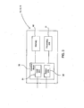
- Figure 1 an exemplary system embodying the present invention is shown.
- Figure 1 illustrates an embodiment where the configuration data for user equipment is generated in a provisioning server and delivered to the user equipment through a network node capable of local communication.
- the network node enables provision of the application (user agent) and the configuration data even in the absence of cellular coverage or alternative means for downloading configuration information, but it is not essential for the implementation of the present invention.
- the transfer mechanism for inputting the configuration data and the user agent capable of a necessary transformation procedure is not, as such, essential for the present invention.
- the specifications of communications systems and particularly wireless communications systems develop rapidly. Therefore, all terms and expressions should be interpreted broadly, since they are intended to illustrate, not to restrict the interpretation of the invention.
- Figure 1 is simplified system architecture and only shows some elements of the architecture of an exemplary system.
- the network nodes shown in Figure 1 are logical units whose implementation may differ from what is shown.
- the logical units may be combined to each other, i.e. a functionality of one logical unit described below may be enhanced to comprise a functionality of another logical unit described below and/or a functionality of a prior art network node (logical unit).
- the connections shown in Figure 1 between network nodes are logical connections; the actual physical connections may be different than the logical connections. It is apparent to a person skilled in the art that the systems also comprise other functions and structures that will not be described in detail herein.
- FIG. 1 illustrates user equipment (UE) 10 of a subscriber of a public land mobile network (PLMN) 11.
- the user equipment of a communication system can be a simplified terminal for speech only or a terminal for diverse services. In the latter case the terminal acts as a service platform and supports loading and execution of various functions related to the services.
- User equipment typically comprises mobile equipment (such as a mobile handset) and a subscriber identity module (SIM), typically a detachably connected identification card.
- SIM subscriber identity module
- the subscriber identity module is typically a smart card that holds the subscriber (network) identity, performs authentication algorithms, and stores authentication and encryption keys and other subscription information that is needed at the mobile user equipment.
- the mobile equipment may be any equipment capable of communicating in a mobile communication system or a combination of several pieces of equipment, for instance a multimedia computer to which a card phone has been connected to provide a mobile telecommunications connection.
- a mobile network refers generally to any telecommunications network that subscribers may access, and wherein the access point to the system may change when users are moving within the service area of the network.
- a typical mobile communications system is a Public Land Mobile Network (PLMN).
- PLMN Public Land Mobile Network
- the mobile communications network is often an access network providing a user with wireless access to external networks, hosts, or services offered by service providers. The configuration of PLMN will be discussed in more detail with reference to Figure 2 .
- Figure 1 illustrates an IP packet data network 12.
- An IP packet data network may comprise one or more networks that enable exchange of information using the Internet protocol.
- the IP packet data network 12 of Figure 1 can thus represent a single local area network, a comprehensive multimode network that connects large numbers of terminals and computers over a wide area, or any combination of such.
- Figure 1 shows also a provisioning system 13 that may communicate with the user equipment 10 through the IP packet data network 12 and PLMN 11, and serves to provide configuration messages to the user equipment 10 of the communication system.
- the provisioning system may be embodied as a server, and is referred to by the general term provisioning server (PS) 13.
- PS provisioning server
- a communication system may comprise one or more provisioning servers.
- a provisioning server may be operated by a PLMN network operator for a variety of services in the network, or by service providers offering different types of services.
- the user equipment 10 is also capable of communicating locally with a network node (NN) 14.
- NW network node
- Local communication in this context refers to any communication that may be performed without involving the network connection, here without the cellular resources of the PLMN 11. Examples of the technologies available for the local communication comprise Wireless Local Area Network (WLAN), Bluetooth, Infrared, use of cables, etc.
- the network node 14 is connected to the IP packet data network 12 and is thus capable of exchanging information with the provisioning server 13.
- a public land mobile network (PLMN) infrastructure may be logically divided into a core network (CN) 216, 218, 220, 222 and access network (AN) infrastructures 208, 210, 212, 214.
- a radio access network AN may thus refer, for example, to a base station subsystem (BSS) 214 for the GSM and radio network subsystem (RNS), or radio access network (RAN) 208, 210, 212 for the UMTS.
- BSS base station subsystem
- RNS radio network subsystem
- RAN radio access network
- the core network CN may be logically divided into a circuit-switched (CS) domain 216, a packet-switched (PS) domain 218, 220 and an IP multimedia subsystem (IMS) 222.
- CS circuit-switched
- PS packet-switched
- IMS IP multimedia subsystem
- the CS domain refers to a set of all the CN entities offering CS type of connection for user traffic as well as all the entities supporting the related signalling.
- a CS type of connection is a connection for which dedicated network resources are allocated when a connection is established and released when the connection is released.
- a PS type of connection transfers the user information using packets so that each packet can be routed independently from the previous one.
- An example of the PS domain may be the GPRS (General Packet Radio Service), and the typical entities may include a serving GPRS support node (SGSN) 228 and a gateway GPRS support node (GGSN) 230.
- the IP multimedia subsystem comprises CN elements for provision of multimedia services.
- the IP multimedia subsystem IMS utilizes the PS domain to transport multimedia signalling and bearer traffic. Consequently, UE accessing the PS core network, and the PS core network itself, utilizes the services provided by the radio access network to provide packet-mode communication between the UE and the PS CN subsystem.
- the multiple access method employed in the air interface in the RAN may be Time Division Multiple Access (TDMA), Frequency Division Multiple Access (FDMA), Code Division Multiple Access (CDMA), or any other method or a combination thereof.
- SMS short messages
- the radio interface of mobile network provides a service access point for short messages. This allows the messages in SMS to be transported as if they were signaling messages meant for a network entity, but they are, in a sense, user traffic because they are delivered to and consumed by the user in the user equipment.
- a packet based media communication system 226 may be provided on top of the mobile network.
- the media communication system is embodied as a server system, and it is generally referred to as an application server.
- a communication system may comprise a plurality of media communication servers.
- the provisioning server 13 may be connected to the IP packet data network 12 and utilize services of the communication system to exchange information with different communication parties. For example, a provisioning server 13 may deliver a configuration message to user equipment in a short message, or to a local network node in a data packet delivered over the IP packet data network 12.
- FIG 3 illustrates a minimum hardware configuration for the implementation of the user equipment 10, provisioning server 13 and network node 14 elements of Figure 1 .
- the element comprises a processing unit 31, an element that comprises an arithmetic logic module, a number of special registers and control circuits.
- a memory unit 32 Connected to the processing unit is a memory unit 32, a data medium where computer-readable data or programs or user data can be stored.
- the memory unit 32 typically comprises memory modules that allow both reading and writing (RAM), and memory modules whose contents can only be read (ROM).
- the unit also comprises an interface block 33 with input unit 34 for inputting data for internal processing in the element, and output unit 35 for outputting data from the internal processes of the element.
- Examples of said input unit in network elements 13, 14 comprise plug-in units acting as a gateway for information delivered to its external connection points.
- the interface block 33 of the network element may also comprise a keypad, or a touch screen, a microphone, or the like (not shown).
- Examples of said output unit 35 in network elements 13,14 include plug-in unit feeding information to the lines connected to its external connection points.
- the interface block 33 of the user equipment 10 typically comprises at least a user interface unit for communicating with the user and a radio interface unit for communication over the cellular mobile network.
- the user equipment may comprise additional interface units, for communication over another type of cellular network, or in another frequency, or for local communication. Examples of the technologies used for the local communication comprise Wireless Local Area Network (WLAN), Wi-Fi, Wi-Max Bluetooth, Infrared, use of cables, etc.
- WLAN Wireless Local Area Network
- Wi-Fi Wireless Fidelity
- Wi-Max Bluetooth Wireless Fidelity
- Infrared use of cables, etc.
- the implementation of such interface units may comprise a plug-in unit exchanging information through lines connected to external connection points of the user equipment, or light/radio transceiver units with appropriate protocol stacks in the user equipment.
- the processing unit 31, memory unit 32, and interface block 33 are electrically interconnected for performing systematic execution of operations on the received and/or stored data according to the predefined, essentially programmed processes of the element.
- the operations comprise functions for implementing the logical units, operations and interfaces of the elements 10, 13, 14 as will be described in the following.
- FIG 4 illustrates some logical units of the user equipment 10, provisioning server 13 and network node 14 elements of Figure 1 used in implementing the current embodiment of the invention.
- the provisioning server 13 comprises a provisioning message generator 401 that through the internal processes of the provisioning server 13 resolves configuration information inf cf,UE 401 a stored in a provisioning database for particular user equipment 10, and creates a provisioning message msg cf 416 comprising the configuration information 401a for delivery to the user equipment 10.
- the provisioning message generator 401 compiles the provisioning message msg cf into a short message, addresses the short message with the user identity of the user of the user equipment 10, and forwards the short message to the radio unit 402 of the provisioning server 13.
- a provisioning message is typically, but not necessarily, formulated as WAP binary encoded provisioning extensible markup language (XML) documents (WBXML).
- the radio unit 402 sends, at request (pull) or without a separate request (push), the short message to the user equipment 10 via the mobile communication network, illustrated as crossing the cellular radio interface (RIF) 403.
- RIF cellular radio interface
- the provisioning message generator 401 of the embodied provisioning server 13 is further configured to compile the provisioning message msg cf into a data packet, address the data packet to a network node 14 authorized to handle configuration messages of the user of the user equipment 10, and forward the data packet to the network unit 404 of the provisioning server.
- the operation to send the configuration message 416 through the network unit 404 may be the primary, or sole functionality of the provisioning message generator 401, or it may be an alternative or secondary functionality initiated when delivery through the radio unit 402 is detected to fail.
- the network unit 404 sends the data packet through the IP packet data network, illustrated as crossing the network interface (NIF) 405.
- the user equipment 10 comprises a configuration database 406 that comprises information on, for example, access points, Session Initiation Protocol (SIP) profiles 406a, and Voice over IP (VoIP) profiles 406b.
- This information may be modified with a formatted message from an authorized source.
- the short message from the provisioning server 13 is received by the radio unit 407 of the user equipment 10, and forwarded to the signal processor 408 of the user equipment.
- the signal processor 408 detects the message to be a configuration message, implements necessary authorization procedures and if the authorization succeeds, implements a requested database operation in the configuration database 406 of the user equipment 10.
- Authorization procedures related to over-the-air (OTA) configuration are generally known to a person skilled in the art and will not be disclosed in more detail herein.
- the network node 14 receives the data packet from the provisioning server 13 through a network unit 409.
- the network unit 409 forwards the data packet to the signal-processing unit 410 of the network node, which detects the data packet to comprise a configuration message msg cf comprising the configuration information for delivery to the user equipment 10.
- the signal-processing unit 410 of the network node creates a local configuration package Icp cf 414 comprising a user agent 415, and the configuration message msg cf 416 (see Figure 4a ) and forwards the local configuration package Icp cf 414 to the local communication unit 411 of the network node.
- the user agent 416 is generic, meaning that the same user agent may be used in the same format for different users, only the configuration message msg cf 416 changes.
- the user agent 415 may be disposable or stored in the user equipment 10 for further use. In case of a disposable user agent, the user agent is deleted from the user equipment after each configuration operation.
- the local configuration package Icp cf 414 comprises the user agent 415 only in the first time it is sent and whenever it needs to be updated. At other times, only the configuration message msg cf 416 needs to be delivered from the network node 14 to the user equipment 10 and so the local configuration package 414 just provides the configuration message as shown in Figure 4b .
- the mechanisms related to the first delivery of the configuration message are disclosed. Adjusting the procedure to the subsequent configuration operations according to the type of the user agent will be, in view of the above, clear to a person skilled in the art and therefore requires no further explanation herein.
- the local communication unit 411 of the network node 14 sends the data package 414 to the user equipment 10 locally, illustrated in Figure 4 as crossing the local communication interface (LIF) 412.
- LIF local communication interface
- examples of the technologies that may be used in the local communication include Wireless Local Area Network (WLAN), Bluetooth, Infrared, use of cables, or the like.
- the local configuration package Icp cf 414 from the local network node 14 is received by the corresponding local communications unit 413 of the user equipment 10, and again forwarded to the signal processor 408 of the user equipment. This time the signal processor 408 detects the message to be a user agent 415, implements necessary authorization procedures and if the authorization succeeds, installs the user agent 415 in the user equipment 10.
- Figure 5 illustrates in more detail the logical modules involved in implementing the current embodiment in the signal-processing unit 408 of the user equipment 10.
- Figure 5 shows the signal-processing unit 408 to comprise a first interface IF1 50 for data streams related to the configuration messages 60, for example data streams from the radio unit 407.
- the signal-processing unit 408 of Figure 5 also comprises a second interface IF2 51 for data streams related to applications, for example data streams from the local communication unit 413.
- the signal-processing unit 408 of Figure 5 also comprises a third interface IF3 52 for data streams to and from the user interface (not shown) of the user equipment. Note that only interfaces necessary for illustrating the embodiment are disclosed herein. Additionally, for a person skilled in the art, it will be clear that the data streams from different interface units may be physically combined between the interface blocks 407, 413 and the signal processing unit 408, and interpreted in the signal processing unit 408 as separate data streams using a defined protocol.
- the different data streams are input to a pre-processor 53 that detects an input dataflow, determines its type and, according to the determined type, implements a predefined pre-processing algorithm 57a which utilises one of a plurality of transforms 57b stored in a local data store 59, and forwards the data stream using a predefined functionality.
- a data stream related to a configuration message msg cf 416 received over the radio interface 407 in one format is manipulated with a predetermined format transformation algorithm 58 into another format applicable for controlling the configuration database operations.
- This predetermined format transformation algorithm 58 is provided by the user equipment manufacturer to enable the user equipment to be configured, typically, remotely using over-the messages such as SMS messages and information relating to it requires involving the user equipment manufacturer. Due to the provision of this format transformation algorithm 58, the network node 14 of a third party cannot directly submit a configuration message msg cf 416 received from the provisioning server 13 to the user equipment 10 in order to implement a configuration database operation.
- the modified configuration message msg cf,P 60 received from the radio interface is forwarded to the inbox 54 of the messaging service used in the radio interface 50.
- this relates to an SMS inbox 54 of the user equipment 10.
- Reception of the configuration data stream in the inbox 54 initiates a user authorization procedure.
- the inbox 54 stores the received data, forwards a message informing the user about an incoming message to the user interface 52, and receives through the use interface 52 the response of the user.
- the authorization succeeds, the inbox 54 forwards the configuration data to the configuration manager 55.
- the configuration manager 55 is a logical module of the signal-processing unit that, according to the information in the received data streams, performs database operations on the configuration database 406.
- the configuration manager 55 amends the records (such as the SIP profiles 406a, the VOIP profiles 406b and other stored user equipment configuration variables) in the configuration database 406 according to the parsed information of the XML document (configuration message 416).
- a local configuration package Icp cf 414 arriving to the user equipment 10 through IF2 51 is detected by the pre-processor 53 to be an application and, typically without substantial pre-processing, forwarded to an application manager 56.
- the application in this embodiment is the user agent 415.
- the application manager 56 is a logical module of the signal processing unit 408 that, according to the information in the received application data streams, performs operations for initiating, ending, and pausing applications, installing the applications and de-installing them, mediating input information to the applications and output information from the applications, and any other tasks necessary for maintaining and running the applications in the user equipment 10.
- the application manager 56 On receiving a data stream, the application manager 56 performs the application operations according to the received application message, for example installs a user agent 415 in the user equipment by storing the received program code of the user agent 415 in the application database 57.
- a local configuration package Icp cf 414 comprises a user agent 415, and the configuration message msg cf 416 (see Figure 4a ).
- the user agent 415 When the user agent 415 is received in the user equipment 10 and installed as described above, it reads the configuration message msg cf 416, initiates a function that performs a predefined algorithm (preprocessing algorithm 57a and transform 57b) that corresponds with the format transformation algorithm 58 in the preprocessor 53 of the signal processing unit, and transforms the configuration message msg cf 416 into the format msg cf,P which is compatible with and understood by the configuration manager 55.
- predefined algorithm preprocessing algorithm 57a and transform 57b
- the user agent inputs the application originated modified configuration message msg cf,P 60 to the inbox 54.
- the modified configuration message 60 is interpreted by the inbox 54 to be a normal over-the-air configuration message 60 (received from the radio unit 407) and an operation for authorizing a configuration operation, as disclosed above, is initiated. If a positive user response is received via the interface 3 52, the inbox 54 interprets the configuration operation as acceptable, and forwards the data to the configuration manager 55, which performs the requested configuration database operation.
- the division of the operations of the network node 14, the configuration manager 55 and the inbox 54 is merely illustrative.
- the functionality for initiating an authorization for a configuration operation may be implemented in the inbox or in the configuration manager.
- the functionality for initiating an authorizing for an application operation may be implemented in the inbox or in the application manager.
- configuring of the user equipment 10 may be performed locally by a third party, i.e. a party that is not the equipment manufacturer or the service provider.
- a third party i.e. a party that is not the equipment manufacturer or the service provider.
- the present embodiment provides a significant advantage for the configuration operations in challenging or non-existent radio environment, for example in the areas of poor network coverage.
- the above structures and functions may be implemented without major changes to the configurations, protocols and/or interfaces of the equipment involved.
- the operations in the network node comprise substantially combining a received configuration message with a generic user agent. This is a straightforward operation, and does not require high technical skills from the operator of the network node 14 (in most of the cases the owner of the user equipment 10).
- the embodiment of the present invention thus provides an easy to use mechanism that may be comfortably distributed to a plurality of users.
- the use of a user agent 415 and an inbox 54 provides a possibility for interaction with the user, and thus provides a further advantage of the present embodiment.
- the user agent 415 may be configured to provide the user with two or more alternative configurations, of which the user may choose the one most advantageous to the current purpose.
- the user agent 415 may be configured to output the current configuration to the user, and provide him or her with the possibility to edit one or more of the parameters of the configuration. This gives a feeling of control, and improves the user-friendliness of the provisioned service.
- the signalling chart of Figure 6 illustrates a method for configuring the user equipment 10 in the embodiment of Figures 1 to 5 .
- the provisioning server PS 13 generates the configuration message msg cf 416, and sends at Step 6-2 it over the IP packet data network to the network node NN 14.
- the network node NN 14 creates at Step 6-3 a local configuration package Icp cf 414 comprising a user agent 415, and the configuration message msg cf 416 and forwards at Step 6-4 the local configuration package Icp cf 414 to the user equipment UE 10.
- the user equipment 414 installs at Step 6-5 the user agent 415.
- the user agent 415 is activated, whereby it reads the configuration message msg cf 416, and performs a predefined algorithm that transforms the configuration message 416 into the format msg cf,P accepted by the configuration manager 55.
- the transformed configuration message 60 is input to the inbox 54 that considers it a normal configuration message 60 and from there on processes the request normally.
- Steps 6-6 to 6-9 illustrate an optional acknowledgement mechanism that may be added to the implementation.
- the user agent 415 may be configured to monitor the progress of the configuration procedure in the user equipment10, and detect whether the procedure was successful or not. In response to the detection, the user equipment 10 may thus return at Step 6-6 to the local network node 14 an OK/NOK message.
- the network node 14 packages this into a format corresponding to a conventional over-the-air acknowledgement message and sends at Step 6-8 the message to the provisioning server 13.
- the provisioning server 13 marks the configuration completed and ends the configuration session at Step 6-9.
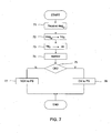
- the flow chart of Figure 7 illustrates a method for configuring user equipment in the embodiment of Figures 1 to 5 from the point of view of the optional network node 14.
- the network node 14 receives at Step 71 the configuration message msg cf 416 and, as described above, creates at Step 72 a local configuration package Icp cf 414 comprising a user agent 415, and the configuration message msg cf 416.
- the network node 14 sends at Step 73 the local configuration package Icp cf 414 to the user equipment 10.
- the optional acknowledgement mechanism is in use, the network node 14 begins to monitor at Step 74 if a response by the user agent 415 installed in the user equipment 10 is received, or if a predefined period for responding is exceeded.
- the network node 14 If a positive response is received at Step 75, the network node 14 generates and sends at Step 76 a positive acknowledgement message to the provisioning server 13. If a negative response is received, or a predefined period for responding is exceeded, the network node 14 generates and sends at Step 77 a negative acknowledgement message to the provisioning server 13.
- the flow chart of Figure 8 illustrates a method for configuring user equipment 10 in the embodiment of Figures 1 to 5 from the point of view of the user equipment 10.
- the user equipment 10 detects at Step 80 the local configuration package Icp cf 414 and interprets it to be a typical user agent 415.
- the user equipment 10 installs at Step 81 the user agent 415 and, according to a request programmed to the application, activates it.
- the user agent 415 performs a predefined transformation algorithm 57a using a stored transform 57b that transforms the configuration message 416 into the format msg cf,P accepted by the configuration manager 55, and inputs the transformed configuration message 60 into the inbox 54 of the user equipment 10.
- the user equipment 10 thus detects at Step 82 the configuration message 60, and initiates a conventional user authorization. If the user response is positive at Step 84, the modified configuration message 60 is forwarded to the configuration manager 55 and the required configuration database operation is performed in the user equipment 10. Otherwise the procedure is terminated at Step 86.
- the user agent 415 monitors at Step 87 the progress of the configuration procedure. If the configuration is successfully completed at Step 87, the user agent 415 generates an OK message that the user equipment 10 sends at Step 89 to the network node 14, and the configuration procedure in the user equipment ends. Otherwise a NOK message is sent at Step 88 and the configuration procedure in the user equipment ends.
- FIG. 9 A further embodiment with reference to Figure 9 to 12 .
- This embodiment is directed to a method and system for securely registering and authenticating subscribers of a communications service.
- the present embodiment is described in the context of a mobile telecommunications device, such as a mobile telephone, the second aspect of the present invention is not limited to this application. Rather, the present invention can be applied to any method or system for securely registering and authenticating subscribers of a communications service.
- the term 'user device' as used herein after refers to user equipment, which in this non-limiting embodiment is a mobile telecommunications device (handset).
- the term 'provisioning server' has the same meaning as that described in the previous embodiment namely to a provisioning system.
- the term 'user credentials' as set out in the present embodiment refers to a username and password. However, this term has a broader meaning, which extends to any means for identifying a user and then permitting verification of that user's identity. An example of this could be a user account number and a PIN.
- the communications channel can be any communications channel that has been described in the previous embodiment, such as that provided by a combination of an IP packet data network 12 and a public land mobile network (PLMN) infrastructure 11 (see Figure 2 ).
- PLMN public land mobile network
- the communications channel comprises a local area network such as a WiFi network a WiFi connection to the Internet (as described in the IEEE 802.11 specification).
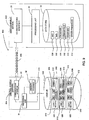
- the user device 502 has a structure as described generally in Figure 3 of the previous embodiment and comprises a processing unit 31, a communications interface 33 and a memory (data store) 32.
- the data store 32 in this embodiment stores unique identifiers for the device itself (an IMEI) 508, for a SIM providing a network identity (IMSI) 510, a configuration program 511 for configuring the user device 502 to operate in the manner to be described below, and optionally, a set of credentials 512 identifying the user uniquely to the service provider (central server 504).
- the data store 32 also stores other programs 514 installed on the device and other identifiers 513 of data stored on the device.
- identifiers examples include the Integrated Circuit Card Identifier (ICCID), the handset agent ID, low level IDs including revision numbers for the mobile device and the programs installed on the mobile device and also code IDs indicating where the programs installed on the device originated from.
- ICCID Integrated Circuit Card Identifier
- Low level IDs including revision numbers for the mobile device and the programs installed on the mobile device and also code IDs indicating where the programs installed on the device originated from.
- Knowledge of these other IDs 513 is very helpful to a provisioning server 504 in that it assists the server in determining the exact capabilities of the device and thus enables more accurate configuration of the device 502.
- the server 504 also has a structure as described previously in Figure 3 of the previous embodiment and comprises a processing unit 31, a communications interface 33 and a memory 32.
- the memory 32 also stores a server program 516 for configuring the server 504 to operate in the manner, which is described below with reference to Figures 10 to 12 .
- the server 504 is provided with a user database 518, which stores a plurality of user records 520 each holding information relating to a subscriber of the service provided by the server 504.
- Each record 520 comprises at least one IMEI 508 and at least one IMSI 510 for the registered subscriber, together with a set of user credentials 512 and the other IDs 513 described above.
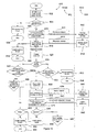
- the method 600 commences with the user device obtaining at Step 602, the configuration program 511 from any source (from a download site, from a supplier website or even from a previously registered subscriber).
- the method 600 continues with the configuration program 511 determining at Step 604 whether the user of the device 502 wishes to register with the service provided by the provisioning server 504. If the user indicates that they do not wish to register, then a warning is displayed at Step 606 to the user on the user device 502 and the method ends, at Step 608. However, if the configuration program 511 determines that the user does wish to register then the configuration program 511 retrieves, at Step 610, the unique device identity and the device's network identity, namely the IMEI 508 and the IMSI 510; these identifiers are simply read from the data store 32.
- the device 502 constructs and then sends, also at Step 610, via the communications channel 506 an asynchronous pre-access request message 611 to the server 504 containing the unique identifiers 508, 510. It is also possible to send some of the other identifiers 513 at this stage such as the ICCID, though this is not essential.
- the server 504 receives, at Step 612, the asynchronous message and determines if any of the identifiers 508, 510 is previously known by searching the plurality of user records 520 stored in its database 518 for a match. If an identifier match for any of the received identifiers occurs, then an asynchronous response message, for example an SMS message, is constructed at Step 614 and sent back to the device 502 via the communications channel 506 which is part of a public communications network that can be assumed to be relatively secure.
- the response message 615 indicates that the user is known to the server. 504, typically by a flag being set in the response message.
- the purpose of sending the response message 615 back to the device 502 is to enable subsequent verification that the user controls the device whose identifiers were passed to the server previously. This can be considered within a mobile environment to be a GSM check, which can be a requirement of the configuration program 511 running on the device 502. If the received identifiers 508, 510 are unknown, the response message 615 is still sent but indicating that that the user is unknown.
- Step 614 the details of the pre-access request 611 are recorded in the server session log (not shown). This can be of use later if an access request 639 needs to be verified as being authentic.
- the program 511 then processes at Step 622 the response message and determines at Step 624 whether the identifiers were known to the server 504. If the device and network identifier pair 508,510 are unknown, the program 511 determines at Step 626 whether a new account record 520 is required or whether an existing account record 520 is to be updated with the new information. If a new account record is required, the method continues at Step 628 as is shown in Figure 12 and is described later. However, if an existing user account record 520 is to be updated with all new unique identifiers then the user credentials are entered at Step 636 (described below).
- Step 630 the user is prompted at Step 630 to enter the user credentials 512 which relate to that account record 520.
- Step 632 the program 511 displays at Step 632 a warning to the user and the method ends at Step 634. If, however, the user credentials 512 are entered at Step 636 (or the device simply retrieves the stored set of credentials 512, such as username and password), then an access request message 639 is constructed which includes the user credentials 512 and the unique information which relates to the previously transmitted identifier pair 508, 510.
- the device 502 then sends at Step 638 the access request message 639 to the server 504 as a synchronous message, for example an HTTPS post.
- the program 511 expects with a synchronous message to receive an automatic confirmation of delivery of the message within the messaging protocol. This assists in the security of the program as such a response can be a requirement of proceeding with the next steps in the operation of the device 502.
- the server 504 receives at Step 640 the synchronous access request message 639 and searches at Step 642 for the credentials 512 in its database 518. It determines at Step 642 if the credentials 512 are correct, and if so, returns a synchronous authentication response message 643 to the device 502 confirming success. If the credentials 512 are incorrect the server 514 returns a synchronous authentication response message 643 to the device 502 indicating failure.
- the device receives, at Step 644, the synchronous authentication result message 643 from the server 504. If the device credentials 512 are incorrect as determined at Step 646, the program 511 informs the user of the failure at Step 648 and determines at Step 650 whether the user wishes to retry. If the user does wish to retry, the user is taken back to the user credential entry stage at Step 636. Alternatively, a warning is presented at Step 652 to the user and the method exits at Step 652. If however the device credentials 512 are determined to be correct at Step 646, then the method 600 progresses to the updating an existing account stage at Step 656 as described below with reference to Figure 11 .
- the configuration program 511 constructs at Step 658 a synchronous update message 659, which contains the device and network identifier pair 508, 510, and all the other identifiers 513 for the programs on the device 502, including the source of the configuration program 511.
- the device 502 then sends at Step 658 the synchronous update message 659 to the server 504.
- the server 504 receives, at Step 660, the update message 659 from the user device 502 and compares at Step 662 its details with those of the user's existing user account record 520 previously determined. If the details stored in the user's account record 520 do not match those provided in the update message 659, the server program 516 knows that there is new information in the update message 659 which has to be added to the user's account record 520. The program 516 then instructs the user database 518 to update, at Step 664, the user account record 520 with the new details. The server then constructs and sends, at Step 666, an update response message 671 which confirms a successful update of the user's account record 520. This response message 671 is sent as a synchronous message to the user device 502.
- a further update confirmation message (not shown) which is an asynchronous message, such as an SMS message which simple confirms at a user level that the update has been successful.
- the server constructs at Step 670, an update response message 671 which confirms an unsuccessful update of the user's account record 520.
- This response message 671 is then sent as a synchronous message to the user device 502.
- the user device receives at Step 672 the update response message 671 and determines at Step 674 whether or not the update was successful.
- the server has updated the user's account record 520, then the user device's account settings (such as those provided in the SIP profiles 406a and the VoIP profiles 406b) are updated, at Step 676, with the new identifiers (new details) to enable the user to try to use this identifier pair at the next time the user device must obtain authorisation from the server.
- the user is then informed, at Step 678, of the successful updating of the user device's account settings and the method 600 ends at Step 680.
- the configuration program 511 informs, at Step 682, the user of this and offers, at Step 684, the user the option of retrying the update procedure. If the user declines this option the method 600 ends at Step 680. Alternatively, if the user accepts, the configuration program retries, at Step 658, constructing and sending the update message 659 to the server 504.
- the method 600 continues assuming there to be no existing account record 520 for the user at the server 504 and the user has chose to create a new account record at Step 626, is now described.
- the method 600 continues with the terms and conditions for the service being presented, at Step 686, to the user.
- the method determines, at Step 688, whether the user accepts these terms and conditions. If they do not, the method ends at Step 690.
- the configuration program 511 constructs at Step 692 a synchronous new account message 693 which contains the device and network identifier pair 508, 510, and all the other identifiers 513 for the programs on the device 502, including the source of the configuration program 511.
- the device 502 then sends at Step 692 the new account message 693 to the server 504.
- the server 504 receives, at Step 694, the new account message 693 from the user device 502 and compares, at Step 696, the identifiers 508, 510 provided in the new account message 693 with those stored in any of the user account records 520. If none of the identifiers 508, 510, stored in any one of the account records 520, match those provided in the new account message 693, the server program 516 instructs the user database 518 to create, at Step 698, a new user account record 520 comprising all of the new user details. The server 504 then constructs and sends, at Step 700, a new account response message 701 to the user device 502.
- the new account response message 701 confirms a successful creation of a new user account record 520 and includes details of the new user account record 520, such as the new user credentials 512 which have been assigned to this account record 520.
- This new account response message 693 is sent as a synchronous message to the user device 502, in view of the user account credentials contained therein.
- the server constructs and sends, at Step 702, a new account response message 701 which confirms an unsuccessful creation of a new user account record 520.
- This new account response message 701 is sent as a synchronous message to the user device 502.
- the user device 502 receives, at Step 704, the new account response message 701 and determines, at Step 706, whether or not the new account record 520 was successfully created.
- the server has created a new user account record 520
- the user device's account settings (such as those provided in the SIP profiles 406a and the VoIP profiles 406b) are saved, at Step 708, with the new identifiers to enable the user to try to use this identifier pair at the next time the user device 502 must obtain authorisation from the server 504.
- the user is then informed, at Step 710, of the successful creation of the new user account record 520 and the method 600 ends at Step 690.
- the configuration program 511 informs, at Step 712, the user of this and offers, at Step 714, the user the option of retrying the new account set up procedure. If the user declines this option, a customer service department is notified, at Step 716, and the method 600 ends at Step 690. Alternatively if the user accepts, the configuration program 511 retries, at Step 692, constructing and sending the new account message 693 to the server 504.
- the above embodiment can be considered to be a method and system for securely registering and authorising users of a telephony service where multiple unique identifiers may be required by each device and network identifier, using both synchronous and asynchronous messaging, whilst preventing the creation of duplicate accounts and ensuring that each unique identifier is verified for the prevention of fraud and other illegal activities.
- the present invention provides a computer program product encoding a computer program of instructions for executing a computer process.
- the present invention provides a computer program distribution medium readable by a computer and encoding a computer program of instructions for executing a computer process.
- the distribution medium may include a computer readable medium, a program storage medium, a record medium, a computer readable memory, a computer readable software distribution package, a computer readable signal, a computer readable telecommunications signal, and/or a computer readable compressed software package.
- Embodiments of the computer process are shown and described in conjunction with Figures 4 to 6 and 9 to 12 .
- the computer program may be executed in the signal-processing unit of the provisioning server, the network node or the user equipment.
Landscapes
- Engineering & Computer Science (AREA)
- Computer Networks & Wireless Communication (AREA)
- Signal Processing (AREA)
- Computing Systems (AREA)
- Computer Hardware Design (AREA)
- Computer Security & Cryptography (AREA)
- Databases & Information Systems (AREA)
- General Engineering & Computer Science (AREA)
- Mobile Radio Communication Systems (AREA)
- Computer And Data Communications (AREA)
- Telephonic Communication Services (AREA)
- Information Retrieval, Db Structures And Fs Structures Therefor (AREA)
- Management, Administration, Business Operations System, And Electronic Commerce (AREA)
Description
- The present invention relates to a method and system for user equipment configuration and more specifically to the process of provisioning user equipment. More particularly, though not exclusively, the present invention concerns a secure and robust communications protocol suitable for enabluing any provisioning system to configure a remote mobile telecommunications device preferably via a local radio network node.
- Advanced communication systems provide a plurality of services that can be enabled, disabled and adjusted to individual users by appropriate provisioning. Accordingly, provisioning configures any required devices; and provides users with access to data and technology resources. The steps of provisioning also include creation, maintenance and deactivation of user objects and user attributes, as they exist in the device.
- The most obvious mechanism to provision a user agent operating on the device is to use the graphical user interface of the device. This, however, is a very laborous task and vulnerable to errors. Client provisioning is an automated mechanism that allows device settings to be configured with a minimum user interaction. In client provisioning, a message containing configuration information for a particular service is sent to a device and after user confirmation that the configuration is allowable is used to configure the device. Nowadays, the most commonly used way of client provisioning is to deliver the configuration information in Wireless Application Protocol (WAP) binary encoded provisioning XML documents (WBXML) via a primary telecommunications channel of the device. In the field of mobile telecommunications, client provisioning is typically carried out over the air (e.g. using a GPRS network) in short messages.
US 2006/0193321 andUS 2003/0108039 describe a method and apparatus for over-the-air (OTA) provisioning of configuration data of this type. A push router is used to deliver provisioning information in XML through SMS messaging. - However, there exist communication situations where client provisioning operations are necessary, but the communication media between the source of the provisioning information and the device is not available. Such a situation occurs, for example, with mobile telecommunication stations in areas of poor network coverage. In a challenging radio environment, the message comprising the provisioning information cannot be delivered to the mobile station and initiation of a new service or reconfiguring an existing one fails. One approach to address poor network coverage issues in some contexts may be to use alternative communication channels to convey the same information, as is described in
EP 1626552 . This is most appropriate to provision of data over channels where the quality of service may vary. Such communication situations are not that unusual, and a clear need for an alternative solution for provisioning exists. One such solution could be local provisioning but this also has some limitations as described below. - A mobile station could provide a local application programming interface (API) to the configuration information database. For several reasons, especially for security, such application programming interface does not exist in the current mobile stations, or is available only to a part of the configuration information.
- According to the state of the art, local provisioning could also be implemented by feeding the information through different, locally available delivery media, for example in a secure card that is read though the subscriber identity module (SIM) input/output interface, or through a Bluetooth, an Infrared (IR) or a Wireless Local Area Network (WLAN) interface, or through a cable. However, the configuration information is in practice manipulated in a proprietary way in the device and the knowledge on format and content of the final configuration request is available only to a very limited group of parties. As the number of services and service providers increases considerably, more and more parties need to access a particular configuration information without the need for or even possibility of contribution by the device manufacturers.
-
US 2006/0106806 teaches a system and method for providing software updates to mobile devices. An update server provides updates to identified mobile devices in response to requests from the mobile device. Downloading of updates is managed by an update manager at the mobile device. -
US 2003/0208567 teaches a method for configuring a network appliance with instructions sent by e-mail. On connecting to the network, the network appliance looks for and downloads new e-mail. A parser extracts configuration instructions from a text file and provides these to the system processor for implementation. - There has been a proliferation of users of communications systems and devices for use in such systems. Access to subscriber services provided by such systems require users to identity themselves and to authenticate in some way their identity. There are several ways in which this is achieved in the prior art. For example, the user can simply have user credentials (such as a user name and password) which enable him or her to identify themselves to the subscriber. However, this manner of registering and authenticating the user to the subscriber is prone to fraud as usernames and passwords can be fraudulently obtained and used on another communications device.
- Alternatively the user's equipment can be used as part of the subscriber's unique identity. For example, a mobile telecommunications device can have a Subscriber Identification Module (SIM) which has a unique network identity - an International Mobile Subscriber Identity (IMSI). Here, the user's network identity can be used to uniquely identify the user to the subscriber service. However, this is also not an ideal solution as is is still possible for an unregistered user to modify the IMSI sent from their communciations device to the subscriber service to match a registered subscriber's IMSI.
- Furthermore, the network identifier does not provide an ideal global solution for international use of the subscriber service. This is becase different network identifiers are required for different countries if roaming charges are to be avoided or local access numbers are to be made available.
- Registration procedures for subscriber services which exist today to try to mitigate fraud opportunites, are lengthy, complex and require a significnat amount of user interaction. Furthermore, these is disadvantaeously a high chance of duplicate account creation when a service is used in a different country.
- It is desired to overcome or substantially reduce at least some of the above-described problems. More particularly, one of the objects of the present invention is to provide a method and corresponding system for implementing the method to provide an improved mechanism for local provisioning of user equipment.
- An approach followed in aspects of the present invention is based on the idea of installing, in the user equipment, a user agent that is capable of transforming a configuration message received from a third party into a format accepted by, namely compatible with, the configuration management routines of the user equipment. The term third party refers to any entity apart from the manufacturer of the user equipment and the user of the equipment.
- According to one aspect of the present invention there is provided a method of configuring user equipment for use in a cellular wireless telecommunications network as defined in
claim 1. - In embodiments, this may involve a method of managing configuration of user equipment, comprising a configuration database modifiable with configuration data input in a first format, and a communications unit for receiving configuration data in a second format, the method comprising: storing a user agent at the user equipment; providing received configuration data in the second format to the user agent; using the user agent to transform the configuration data into the first format in the user equipment; and modifying the configuration database with the configuration data in the first format.
- This approach provides a local provisioning method which advantageously does not require any user equipment manufacturer's contribution to implement the configuration. The present invention is also completely scalable with the ever-increasing number of services and service providers.
- The user equipment typically comprises an inbox from which the configuration database receives configuration data in the first format and the method may further comprise inputting the configuration data transformed into the first format into the inbox. This advantageously provides a non-intrusive way of implementing the present invention, which maintains the much of the data flows with the user equipment whilst at the same time facilitating correct format conversion for configuration purposes.
- Preferably the communications unit comprises a local radio communications unit for receiving the configuration data in the second format. The local radio channel advantageously provides a simple and straightforward implementation of configuration operations in any environment, including a challenging radio environment, to a plurality of users and service providers. The present invention also simplifies provisioning in circumstances where the radio environment is benign by reducing the provisioning actions and reducing the potential for user error or errors caused by the network, such as out of order delivery.
- Preferably the method further comprises receiving the user agent and the configuration together in a local configuration package. This presents a simple mechanism for facilitating the required local provisioning.
- The method may advantageously further comprise generating a reconfiguration result message and transmitting the same to the source of the configuration message via the communications unit. This enable the source of the reconfiguration operation to keep track of the successful provisioning of the user equipment and allows the source ensure that the provisioning is actually effected.
- The method may further comprise deleting the user agent after the transforming step has been performed. This is advantageous in situations where the user equipment may have severe memory limitations and so the storing of an agent is not required.
- Preferably the user agent comprises a generic user agent and the method may further comprise reusing the user agent for transforming subsequent configuration messages. In situations where there is a high frequency of reconfigurations of user equipment there is no need to send the user agent repeatedly. This feature is highly advantageous in terms of efficiency in these circumstances in implementing the third party reconfigurations.
- In a further aspect of the invention, there is provided user equipment for use in a cellular wireless telecommunications network as defined in claim 5.
- This approach may involve user equipment for a communication system, the user equipment comprising: a configuration database modifiable with configuration data in a first format; a communications unit for receiving configuration data in a second format: a user agent configured to transform received configuration data into the first format; a configuration manager for modifying the configuration database with the transformed configuration data.
- In the following the invention will be described in greater detail by means of preferred embodiments with reference to the accompanying drawings, in which:
-
Figure 1 is a schematic block diagram illustrating elements involved in configuring user equipment of a communication system in accordance with an embodiment of the present invention; -
Figure 2 is a schematic block diagram illustrating a configuration of a public land mobile network ofFigure 1 ; -
Figure 3 is a schematic block diagram illustrating a minimum hardware configuration for the provisioning server, network node and user equipment ofFigure 1 ; -
Figure 4 is a schematic block diagram illustrating logical units of each of the provisioning server, network node and user equipment ofFigure 1 ; -
Figure 5 is a schematic block diagram illustrating the logical modules in the signal processing unit of the user equipment ofFigure 4 ; -
Figure 6 is a signalling chart illustrating a method for configuring the user equipment in the embodiment shown inFigures 1 to 5 ; -
Figure 7 is a flow chart illustrating a method of configuring the user equipment in the embodiment ofFigures 1 to 5 from the point of view of the network node; -
Figure 8 is a flow chart illustrating a method of configuring the user equipment in the embodiment ofFigures 1 to 5 from the point of view of the user equipment; -
Figure 9 is a schematic block diagram showing a provisioning server and user equipment seeking to securely register and be authorised to use the service provided by the provisioning server in accordance with an embodiment of the present invention; -
Figure 10 is a flow chart illustrating a method of registering the user equipment to the provisioning system ofFigure 9 ; -
Figure 11 is a flow chart illustrating a continuation of the method ofFigure 10 showing the case where there is an existing account for the user equipment; and -
Figure 12 is a flow chart illustrating a continuation of the method ofFigure 10 showing the case where there is a new account to be created for the user equipment. - The embodiments of the present invention described below are applicable to any communication system capable of providing communication services that may be individually provisioned to users of the communication system. Such systems include mobile communication systems, fixed telecommunication systems, and a variety of clustered combinations of them. However, in the following, the present embodiments are described in the context of configuring mobile user equipment.
- Referring to
Figure 1 , an exemplary system embodying the present invention is shown. As an advantageous arrangement,Figure 1 illustrates an embodiment where the configuration data for user equipment is generated in a provisioning server and delivered to the user equipment through a network node capable of local communication. The network node enables provision of the application (user agent) and the configuration data even in the absence of cellular coverage or alternative means for downloading configuration information, but it is not essential for the implementation of the present invention. The transfer mechanism for inputting the configuration data and the user agent capable of a necessary transformation procedure is not, as such, essential for the present invention. The specifications of communications systems and particularly wireless communications systems develop rapidly. Therefore, all terms and expressions should be interpreted broadly, since they are intended to illustrate, not to restrict the interpretation of the invention. -
Figure 1 is simplified system architecture and only shows some elements of the architecture of an exemplary system. The network nodes shown inFigure 1 are logical units whose implementation may differ from what is shown. The logical units may be combined to each other, i.e. a functionality of one logical unit described below may be enhanced to comprise a functionality of another logical unit described below and/or a functionality of a prior art network node (logical unit). Additionally, the connections shown inFigure 1 between network nodes are logical connections; the actual physical connections may be different than the logical connections. It is apparent to a person skilled in the art that the systems also comprise other functions and structures that will not be described in detail herein. -
Figure 1 illustrates user equipment (UE) 10 of a subscriber of a public land mobile network (PLMN) 11. The user equipment of a communication system can be a simplified terminal for speech only or a terminal for diverse services. In the latter case the terminal acts as a service platform and supports loading and execution of various functions related to the services. User equipment typically comprises mobile equipment (such as a mobile handset) and a subscriber identity module (SIM), typically a detachably connected identification card. In this context, the user equipment thus refers to the entity formed by the subscriber identity module and the actual mobile equipment. The subscriber identity module is typically a smart card that holds the subscriber (network) identity, performs authentication algorithms, and stores authentication and encryption keys and other subscription information that is needed at the mobile user equipment. The mobile equipment may be any equipment capable of communicating in a mobile communication system or a combination of several pieces of equipment, for instance a multimedia computer to which a card phone has been connected to provide a mobile telecommunications connection. - A mobile network refers generally to any telecommunications network that subscribers may access, and wherein the access point to the system may change when users are moving within the service area of the network. A typical mobile communications system is a Public Land Mobile Network (PLMN). The mobile communications network is often an access network providing a user with wireless access to external networks, hosts, or services offered by service providers. The configuration of PLMN will be discussed in more detail with reference to
Figure 2 . - As an example of external networks,
Figure 1 illustrates an IPpacket data network 12. An IP packet data network may comprise one or more networks that enable exchange of information using the Internet protocol. The IPpacket data network 12 ofFigure 1 can thus represent a single local area network, a comprehensive multimode network that connects large numbers of terminals and computers over a wide area, or any combination of such. -
Figure 1 shows also aprovisioning system 13 that may communicate with theuser equipment 10 through the IPpacket data network 12 andPLMN 11, and serves to provide configuration messages to theuser equipment 10 of the communication system. The provisioning system may be embodied as a server, and is referred to by the general term provisioning server (PS) 13. A communication system may comprise one or more provisioning servers. A provisioning server may be operated by a PLMN network operator for a variety of services in the network, or by service providers offering different types of services. - The
user equipment 10 is also capable of communicating locally with a network node (NN) 14. Local communication in this context refers to any communication that may be performed without involving the network connection, here without the cellular resources of thePLMN 11. Examples of the technologies available for the local communication comprise Wireless Local Area Network (WLAN), Bluetooth, Infrared, use of cables, etc. Thenetwork node 14 is connected to the IPpacket data network 12 and is thus capable of exchanging information with theprovisioning server 13. - As illustrated in
Fig 2 , in mobile communications systems, a public land mobile network (PLMN) infrastructure may be logically divided into a core network (CN) 216, 218, 220, 222 and access network (AN)infrastructures - The core network CN may be logically divided into a circuit-switched (CS)
domain 216, a packet-switched (PS)domain - The CS domain refers to a set of all the CN entities offering CS type of connection for user traffic as well as all the entities supporting the related signalling. A CS type of connection is a connection for which dedicated network resources are allocated when a connection is established and released when the connection is released.
- A PS type of connection transfers the user information using packets so that each packet can be routed independently from the previous one. An example of the PS domain may be the GPRS (General Packet Radio Service), and the typical entities may include a serving GPRS support node (SGSN) 228 and a gateway GPRS support node (GGSN) 230. The IP multimedia subsystem comprises CN elements for provision of multimedia services. The IP multimedia subsystem IMS utilizes the PS domain to transport multimedia signalling and bearer traffic. Consequently, UE accessing the PS core network, and the PS core network itself, utilizes the services provided by the radio access network to provide packet-mode communication between the UE and the PS CN subsystem. The multiple access method employed in the air interface in the RAN may be Time Division Multiple Access (TDMA), Frequency Division Multiple Access (FDMA), Code Division Multiple Access (CDMA), or any other method or a combination thereof.
- For delivery of configuration messages, mobile networks also provide an additional service for short messages (SMS). The radio interface of mobile network provides a service access point for short messages. This allows the messages in SMS to be transported as if they were signaling messages meant for a network entity, but they are, in a sense, user traffic because they are delivered to and consumed by the user in the user equipment.
- In order to provide media communication services to the user equipment through the communication system, a packet based
media communication system 226 may be provided on top of the mobile network. InFigure 2 , the media communication system is embodied as a server system, and it is generally referred to as an application server. A communication system may comprise a plurality of media communication servers. - As shown in
Figure 2 , theprovisioning server 13 may be connected to the IPpacket data network 12 and utilize services of the communication system to exchange information with different communication parties. For example, aprovisioning server 13 may deliver a configuration message to user equipment in a short message, or to a local network node in a data packet delivered over the IPpacket data network 12. -
Figure 3 illustrates a minimum hardware configuration for the implementation of theuser equipment 10, provisioningserver 13 andnetwork node 14 elements ofFigure 1 . The element comprises aprocessing unit 31, an element that comprises an arithmetic logic module, a number of special registers and control circuits. Connected to the processing unit is amemory unit 32, a data medium where computer-readable data or programs or user data can be stored. Thememory unit 32 typically comprises memory modules that allow both reading and writing (RAM), and memory modules whose contents can only be read (ROM). The unit also comprises aninterface block 33 withinput unit 34 for inputting data for internal processing in the element, andoutput unit 35 for outputting data from the internal processes of the element. - Examples of said input unit in
network elements interface block 33 of the network element may also comprise a keypad, or a touch screen, a microphone, or the like (not shown). Examples of saidoutput unit 35 innetwork elements network element 14, they may also comprise a screen, a touch screen, a loudspeaker, or the like (not shown). - The
interface block 33 of theuser equipment 10 typically comprises at least a user interface unit for communicating with the user and a radio interface unit for communication over the cellular mobile network. In addition, the user equipment may comprise additional interface units, for communication over another type of cellular network, or in another frequency, or for local communication. Examples of the technologies used for the local communication comprise Wireless Local Area Network (WLAN), Wi-Fi, Wi-Max Bluetooth, Infrared, use of cables, etc. Depending on the application, the implementation of such interface units may comprise a plug-in unit exchanging information through lines connected to external connection points of the user equipment, or light/radio transceiver units with appropriate protocol stacks in the user equipment. - The
processing unit 31,memory unit 32, andinterface block 33 are electrically interconnected for performing systematic execution of operations on the received and/or stored data according to the predefined, essentially programmed processes of the element. In the present embodiments, the operations comprise functions for implementing the logical units, operations and interfaces of theelements -
Figure 4 illustrates some logical units of theuser equipment 10, provisioningserver 13 andnetwork node 14 elements ofFigure 1 used in implementing the current embodiment of the invention. Theprovisioning server 13 comprises aprovisioning message generator 401 that through the internal processes of theprovisioning server 13 resolves configuration information infcf,UE 401 a stored in a provisioning database forparticular user equipment 10, and creates a provisioning message msgcf 416 comprising theconfiguration information 401a for delivery to theuser equipment 10. In a conventional system, theprovisioning message generator 401 compiles the provisioning message msgcf into a short message, addresses the short message with the user identity of the user of theuser equipment 10, and forwards the short message to theradio unit 402 of theprovisioning server 13. A provisioning message is typically, but not necessarily, formulated as WAP binary encoded provisioning extensible markup language (XML) documents (WBXML). Theradio unit 402 sends, at request (pull) or without a separate request (push), the short message to theuser equipment 10 via the mobile communication network, illustrated as crossing the cellular radio interface (RIF) 403. - The
provisioning message generator 401 of the embodiedprovisioning server 13 is further configured to compile the provisioning message msgcf into a data packet, address the data packet to anetwork node 14 authorized to handle configuration messages of the user of theuser equipment 10, and forward the data packet to thenetwork unit 404 of the provisioning server. The operation to send theconfiguration message 416 through thenetwork unit 404 may be the primary, or sole functionality of theprovisioning message generator 401, or it may be an alternative or secondary functionality initiated when delivery through theradio unit 402 is detected to fail. Thenetwork unit 404 sends the data packet through the IP packet data network, illustrated as crossing the network interface (NIF) 405. - The
user equipment 10 comprises aconfiguration database 406 that comprises information on, for example, access points, Session Initiation Protocol (SIP) profiles 406a, and Voice over IP (VoIP) profiles 406b. This information may be modified with a formatted message from an authorized source. In the conventional way, the short message from theprovisioning server 13 is received by theradio unit 407 of theuser equipment 10, and forwarded to thesignal processor 408 of the user equipment. Thesignal processor 408 detects the message to be a configuration message, implements necessary authorization procedures and if the authorization succeeds, implements a requested database operation in theconfiguration database 406 of theuser equipment 10. Authorization procedures related to over-the-air (OTA) configuration are generally known to a person skilled in the art and will not be disclosed in more detail herein. - In the embodied solution, the
network node 14 receives the data packet from theprovisioning server 13 through anetwork unit 409. Thenetwork unit 409 forwards the data packet to the signal-processing unit 410 of the network node, which detects the data packet to comprise a configuration message msgcf comprising the configuration information for delivery to theuser equipment 10. The signal-processing unit 410 of the network node creates a localconfiguration package Icp cf 414 comprising auser agent 415, and the configuration message msgcf 416 (seeFigure 4a ) and forwards the localconfiguration package Icp cf 414 to thelocal communication unit 411 of the network node. Theuser agent 416 is generic, meaning that the same user agent may be used in the same format for different users, only the configuration message msgcf 416 changes. Additionally, theuser agent 415 may be disposable or stored in theuser equipment 10 for further use. In case of a disposable user agent, the user agent is deleted from the user equipment after each configuration operation. In case of a storeduser agent 415, the localconfiguration package Icp cf 414 comprises theuser agent 415 only in the first time it is sent and whenever it needs to be updated. At other times, only the configuration message msgcf 416 needs to be delivered from thenetwork node 14 to theuser equipment 10 and so thelocal configuration package 414 just provides the configuration message as shown inFigure 4b . In the following embodiment, the mechanisms related to the first delivery of the configuration message are disclosed. Adjusting the procedure to the subsequent configuration operations according to the type of the user agent will be, in view of the above, clear to a person skilled in the art and therefore requires no further explanation herein. - The
local communication unit 411 of thenetwork node 14 sends thedata package 414 to theuser equipment 10 locally, illustrated inFigure 4 as crossing the local communication interface (LIF) 412. As discussed above, examples of the technologies that may be used in the local communication include Wireless Local Area Network (WLAN), Bluetooth, Infrared, use of cables, or the like. - The local
configuration package Icp cf 414 from thelocal network node 14 is received by the correspondinglocal communications unit 413 of theuser equipment 10, and again forwarded to thesignal processor 408 of the user equipment. This time thesignal processor 408 detects the message to be auser agent 415, implements necessary authorization procedures and if the authorization succeeds, installs theuser agent 415 in theuser equipment 10. -
Figure 5 illustrates in more detail the logical modules involved in implementing the current embodiment in the signal-processing unit 408 of theuser equipment 10.Figure 5 shows the signal-processing unit 408 to comprise afirst interface IF1 50 for data streams related to theconfiguration messages 60, for example data streams from theradio unit 407. The signal-processing unit 408 ofFigure 5 also comprises asecond interface IF2 51 for data streams related to applications, for example data streams from thelocal communication unit 413. The signal-processing unit 408 ofFigure 5 also comprises athird interface IF3 52 for data streams to and from the user interface (not shown) of the user equipment. Note that only interfaces necessary for illustrating the embodiment are disclosed herein. Additionally, for a person skilled in the art, it will be clear that the data streams from different interface units may be physically combined between the interface blocks 407, 413 and thesignal processing unit 408, and interpreted in thesignal processing unit 408 as separate data streams using a defined protocol. - The different data streams are input to a pre-processor 53 that detects an input dataflow, determines its type and, according to the determined type, implements a
predefined pre-processing algorithm 57a which utilises one of a plurality oftransforms 57b stored in alocal data store 59, and forwards the data stream using a predefined functionality. Typically, a data stream related to a configuration message msgcf 416 received over theradio interface 407 in one format is manipulated with a predeterminedformat transformation algorithm 58 into another format applicable for controlling the configuration database operations. This predeterminedformat transformation algorithm 58 is provided by the user equipment manufacturer to enable the user equipment to be configured, typically, remotely using over-the messages such as SMS messages and information relating to it requires involving the user equipment manufacturer. Due to the provision of thisformat transformation algorithm 58, thenetwork node 14 of a third party cannot directly submit a configuration message msgcf 416 received from theprovisioning server 13 to theuser equipment 10 in order to implement a configuration database operation. - The modified configuration message msgcf,P 60 received from the radio interface is forwarded to the
inbox 54 of the messaging service used in theradio interface 50. In the present embodiment this relates to anSMS inbox 54 of theuser equipment 10. Reception of the configuration data stream in theinbox 54 initiates a user authorization procedure. During the user authorization procedure, theinbox 54 stores the received data, forwards a message informing the user about an incoming message to theuser interface 52, and receives through theuse interface 52 the response of the user. In the case the authorization succeeds, theinbox 54 forwards the configuration data to theconfiguration manager 55. Theconfiguration manager 55 is a logical module of the signal-processing unit that, according to the information in the received data streams, performs database operations on theconfiguration database 406. In the embodied example, theconfiguration manager 55 amends the records (such as theSIP profiles 406a, the VOIP profiles 406b and other stored user equipment configuration variables) in theconfiguration database 406 according to the parsed information of the XML document (configuration message 416). - A local
configuration package Icp cf 414 arriving to theuser equipment 10 throughIF2 51 is detected by the pre-processor 53 to be an application and, typically without substantial pre-processing, forwarded to anapplication manager 56. The application in this embodiment is theuser agent 415. Theapplication manager 56 is a logical module of thesignal processing unit 408 that, according to the information in the received application data streams, performs operations for initiating, ending, and pausing applications, installing the applications and de-installing them, mediating input information to the applications and output information from the applications, and any other tasks necessary for maintaining and running the applications in theuser equipment 10. - On receiving a data stream, the
application manager 56 performs the application operations according to the received application message, for example installs auser agent 415 in the user equipment by storing the received program code of theuser agent 415 in theapplication database 57. - In the present embodiment, a local
configuration package Icp cf 414 comprises auser agent 415, and the configuration message msgcf 416 (seeFigure 4a ). When theuser agent 415 is received in theuser equipment 10 and installed as described above, it reads theconfiguration message msg cf 416, initiates a function that performs a predefined algorithm (preprocessingalgorithm 57a and transform 57b) that corresponds with theformat transformation algorithm 58 in thepreprocessor 53 of the signal processing unit, and transforms the configuration message msgcf 416 into the format msgcf,P which is compatible with and understood by theconfiguration manager 55. Furthermore, the user agent inputs the application originated modified configuration message msgcf,P 60 to theinbox 54. The modifiedconfiguration message 60 is interpreted by theinbox 54 to be a normal over-the-air configuration message 60 (received from the radio unit 407) and an operation for authorizing a configuration operation, as disclosed above, is initiated. If a positive user response is received via theinterface 3 52, theinbox 54 interprets the configuration operation as acceptable, and forwards the data to theconfiguration manager 55, which performs the requested configuration database operation. - It should be noted that the division of the operations of the
network node 14, theconfiguration manager 55 and theinbox 54 is merely illustrative. For example, the functionality for initiating an authorization for a configuration operation may be implemented in the inbox or in the configuration manager. Correspondingly, the functionality for initiating an authorizing for an application operation may be implemented in the inbox or in the application manager. - Through the above disclosed device structures and functions, configuring of the
user equipment 10 may be performed locally by a third party, i.e. a party that is not the equipment manufacturer or the service provider. This has not been possible before and therefore the present embodiment provides a significant advantage for the configuration operations in challenging or non-existent radio environment, for example in the areas of poor network coverage. The above structures and functions may be implemented without major changes to the configurations, protocols and/or interfaces of the equipment involved. Additionally, the operations in the network node comprise substantially combining a received configuration message with a generic user agent. This is a straightforward operation, and does not require high technical skills from the operator of the network node 14 (in most of the cases the owner of the user equipment 10). The embodiment of the present invention thus provides an easy to use mechanism that may be comfortably distributed to a plurality of users. - The use of a
user agent 415 and aninbox 54 provides a possibility for interaction with the user, and thus provides a further advantage of the present embodiment. Theuser agent 415 may be configured to provide the user with two or more alternative configurations, of which the user may choose the one most advantageous to the current purpose. Alternatively, theuser agent 415 may be configured to output the current configuration to the user, and provide him or her with the possibility to edit one or more of the parameters of the configuration. This gives a feeling of control, and improves the user-friendliness of the provisioned service. - The signalling chart of
Figure 6 illustrates a method for configuring theuser equipment 10 in the embodiment ofFigures 1 to 5 . In Step 6-1, theprovisioning server PS 13 generates theconfiguration message msg cf 416, and sends at Step 6-2 it over the IP packet data network to thenetwork node NN 14. Thenetwork node NN 14 creates at Step 6-3 a localconfiguration package Icp cf 414 comprising auser agent 415, and theconfiguration message msg cf 416 and forwards at Step 6-4 the localconfiguration package Icp cf 414 to theuser equipment UE 10. Theuser equipment 414 installs at Step 6-5 theuser agent 415. At the end of installation, theuser agent 415 is activated, whereby it reads theconfiguration message msg cf 416, and performs a predefined algorithm that transforms theconfiguration message 416 into the format msgcf,P accepted by theconfiguration manager 55. The transformedconfiguration message 60 is input to theinbox 54 that considers it anormal configuration message 60 and from there on processes the request normally. - Steps 6-6 to 6-9 illustrate an optional acknowledgement mechanism that may be added to the implementation. The
user agent 415 may be configured to monitor the progress of the configuration procedure in the user equipment10, and detect whether the procedure was successful or not. In response to the detection, theuser equipment 10 may thus return at Step 6-6 to thelocal network node 14 an OK/NOK message. Thenetwork node 14 packages this into a format corresponding to a conventional over-the-air acknowledgement message and sends at Step 6-8 the message to theprovisioning server 13. Theprovisioning server 13 marks the configuration completed and ends the configuration session at Step 6-9. - The flow chart of
Figure 7 illustrates a method for configuring user equipment in the embodiment ofFigures 1 to 5 from the point of view of theoptional network node 14. Thenetwork node 14 receives atStep 71 theconfiguration message msg cf 416 and, as described above, creates at Step 72 a localconfiguration package Icp cf 414 comprising auser agent 415, and theconfiguration message msg cf 416. Thenetwork node 14 sends atStep 73 the localconfiguration package Icp cf 414 to theuser equipment 10. In case the optional acknowledgement mechanism is in use, thenetwork node 14 begins to monitor atStep 74 if a response by theuser agent 415 installed in theuser equipment 10 is received, or if a predefined period for responding is exceeded. If a positive response is received atStep 75, thenetwork node 14 generates and sends at Step 76 a positive acknowledgement message to theprovisioning server 13. If a negative response is received, or a predefined period for responding is exceeded, thenetwork node 14 generates and sends at Step 77 a negative acknowledgement message to theprovisioning server 13. - The flow chart of
Figure 8 illustrates a method for configuringuser equipment 10 in the embodiment ofFigures 1 to 5 from the point of view of theuser equipment 10. Theuser equipment 10 detects atStep 80 the localconfiguration package Icp cf 414 and interprets it to be atypical user agent 415. Theuser equipment 10 installs atStep 81 theuser agent 415 and, according to a request programmed to the application, activates it. As described above, theuser agent 415 performs apredefined transformation algorithm 57a using a storedtransform 57b that transforms theconfiguration message 416 into the format msgcf,P accepted by theconfiguration manager 55, and inputs the transformedconfiguration message 60 into theinbox 54 of theuser equipment 10. Theuser equipment 10 thus detects atStep 82 theconfiguration message 60, and initiates a conventional user authorization. If the user response is positive at Step 84, the modifiedconfiguration message 60 is forwarded to theconfiguration manager 55 and the required configuration database operation is performed in theuser equipment 10. Otherwise the procedure is terminated atStep 86. - In case the optional acknowledgement mechanism is in use, the
user agent 415 monitors atStep 87 the progress of the configuration procedure. If the configuration is successfully completed atStep 87, theuser agent 415 generates an OK message that theuser equipment 10 sends atStep 89 to thenetwork node 14, and the configuration procedure in the user equipment ends. Otherwise a NOK message is sent at Step 88 and the configuration procedure in the user equipment ends. - A further embodiment with reference to
Figure 9 to 12 . This embodiment is directed to a method and system for securely registering and authenticating subscribers of a communications service. - Whilst the present embodiment is described in the context of a mobile telecommunications device, such as a mobile telephone, the second aspect of the present invention is not limited to this application. Rather, the present invention can be applied to any method or system for securely registering and authenticating subscribers of a communications service.
- The term 'user device' as used herein after refers to user equipment, which in this non-limiting embodiment is a mobile telecommunications device (handset). The term 'provisioning server' has the same meaning as that described in the previous embodiment namely to a provisioning system. The term 'user credentials' as set out in the present embodiment refers to a username and password. However, this term has a broader meaning, which extends to any means for identifying a user and then permitting verification of that user's identity. An example of this could be a user account number and a PIN.
- Referring now to
Figure 9 , there is shown asystem 500 comprising auser device 502 and aprovisioning server 504 for providing a service to the user device via acommunications channel 506. The communications channel can be any communications channel that has been described in the previous embodiment, such as that provided by a combination of an IPpacket data network 12 and a public land mobile network (PLMN) infrastructure 11 (seeFigure 2 ). However, preferably the communications channel comprises a local area network such as a WiFi network a WiFi connection to the Internet (as described in the IEEE 802.11 specification). - The
user device 502 has a structure as described generally inFigure 3 of the previous embodiment and comprises aprocessing unit 31, acommunications interface 33 and a memory (data store) 32. However, thedata store 32 in this embodiment stores unique identifiers for the device itself (an IMEI) 508, for a SIM providing a network identity (IMSI) 510, aconfiguration program 511 for configuring theuser device 502 to operate in the manner to be described below, and optionally, a set ofcredentials 512 identifying the user uniquely to the service provider (central server 504). Thedata store 32 also storesother programs 514 installed on the device andother identifiers 513 of data stored on the device. Examples of such identifiers include the Integrated Circuit Card Identifier (ICCID), the handset agent ID, low level IDs including revision numbers for the mobile device and the programs installed on the mobile device and also code IDs indicating where the programs installed on the device originated from. Knowledge of theseother IDs 513 is very helpful to aprovisioning server 504 in that it assists the server in determining the exact capabilities of the device and thus enables more accurate configuration of thedevice 502. - The
server 504 also has a structure as described previously inFigure 3 of the previous embodiment and comprises aprocessing unit 31, acommunications interface 33 and amemory 32. Thememory 32 also stores aserver program 516 for configuring theserver 504 to operate in the manner, which is described below with reference toFigures 10 to 12 . Also in this instance theserver 504 is provided with auser database 518, which stores a plurality ofuser records 520 each holding information relating to a subscriber of the service provided by theserver 504. Eachrecord 520 comprises at least oneIMEI 508 and at least oneIMSI 510 for the registered subscriber, together with a set ofuser credentials 512 and theother IDs 513 described above. - Referring now to
Figure 10 , a method of registering the user device to theprovisioning server 504 is described. Themethod 600 commences with the user device obtaining atStep 602, theconfiguration program 511 from any source (from a download site, from a supplier website or even from a previously registered subscriber). - The
method 600 continues with theconfiguration program 511 determining atStep 604 whether the user of thedevice 502 wishes to register with the service provided by theprovisioning server 504. If the user indicates that they do not wish to register, then a warning is displayed atStep 606 to the user on theuser device 502 and the method ends, atStep 608. However, if theconfiguration program 511 determines that the user does wish to register then theconfiguration program 511 retrieves, atStep 610, the unique device identity and the device's network identity, namely theIMEI 508 and theIMSI 510; these identifiers are simply read from thedata store 32. - The
device 502 constructs and then sends, also atStep 610, via thecommunications channel 506 an asynchronouspre-access request message 611 to theserver 504 containing theunique identifiers other identifiers 513 at this stage such as the ICCID, though this is not essential. - The
server 504 receives, atStep 612, the asynchronous message and determines if any of theidentifiers user records 520 stored in itsdatabase 518 for a match. If an identifier match for any of the received identifiers occurs, then an asynchronous response message, for example an SMS message, is constructed atStep 614 and sent back to thedevice 502 via thecommunications channel 506 which is part of a public communications network that can be assumed to be relatively secure. Theresponse message 615 indicates that the user is known to the server. 504, typically by a flag being set in the response message. The purpose of sending theresponse message 615 back to thedevice 502 is to enable subsequent verification that the user controls the device whose identifiers were passed to the server previously. This can be considered within a mobile environment to be a GSM check, which can be a requirement of theconfiguration program 511 running on thedevice 502. If the receivedidentifiers response message 615 is still sent but indicating that that the user is unknown. - Also, whether or not there is a match at
Step 614, the details of thepre-access request 611 are recorded in the server session log (not shown). This can be of use later if anaccess request 639 needs to be verified as being authentic. - The
program 511 then processes atStep 622 the response message and determines atStep 624 whether the identifiers were known to theserver 504. If the device and network identifier pair 508,510 are unknown, theprogram 511 determines atStep 626 whether anew account record 520 is required or whether an existingaccount record 520 is to be updated with the new information. If a new account record is required, the method continues atStep 628 as is shown inFigure 12 and is described later. However, if an existinguser account record 520 is to be updated with all new unique identifiers then the user credentials are entered at Step 636 (described below). - If the device and
network identifier pair Step 622, the user is prompted atStep 630 to enter theuser credentials 512 which relate to thataccount record 520. - If
such user credentials 512 are not entered, then theprogram 511 displays at Step 632 a warning to the user and the method ends atStep 634. If, however, theuser credentials 512 are entered at Step 636 (or the device simply retrieves the stored set ofcredentials 512, such as username and password), then anaccess request message 639 is constructed which includes theuser credentials 512 and the unique information which relates to the previously transmittedidentifier pair - The
device 502 then sends atStep 638 theaccess request message 639 to theserver 504 as a synchronous message, for example an HTTPS post. Theprogram 511 expects with a synchronous message to receive an automatic confirmation of delivery of the message within the messaging protocol. This assists in the security of the program as such a response can be a requirement of proceeding with the next steps in the operation of thedevice 502. - The
server 504 receives atStep 640 the synchronousaccess request message 639 and searches atStep 642 for thecredentials 512 in itsdatabase 518. It determines atStep 642 if thecredentials 512 are correct, and if so, returns a synchronousauthentication response message 643 to thedevice 502 confirming success. If thecredentials 512 are incorrect theserver 514 returns a synchronousauthentication response message 643 to thedevice 502 indicating failure. - The device receives, at
Step 644, the synchronousauthentication result message 643 from theserver 504. If thedevice credentials 512 are incorrect as determined atStep 646, theprogram 511 informs the user of the failure atStep 648 and determines atStep 650 whether the user wishes to retry. If the user does wish to retry, the user is taken back to the user credential entry stage atStep 636. Alternatively, a warning is presented atStep 652 to the user and the method exits atStep 652. If however thedevice credentials 512 are determined to be correct atStep 646, then themethod 600 progresses to the updating an existing account stage atStep 656 as described below with reference toFigure 11 . - Referring to
Figure 11 , the updating an existingaccount record stage 656 of themethod 600 is described. This stage progresses on the assumption that the user device has been successful with itsaccess request 639 as determined atStep 646 ofFigure 10 such that there is an existingaccount record 520 for the user at theserver 504. - The
configuration program 511 constructs at Step 658 asynchronous update message 659, which contains the device andnetwork identifier pair other identifiers 513 for the programs on thedevice 502, including the source of theconfiguration program 511. Thedevice 502 then sends atStep 658 thesynchronous update message 659 to theserver 504. - The
server 504 receives, atStep 660, theupdate message 659 from theuser device 502 and compares atStep 662 its details with those of the user's existinguser account record 520 previously determined. If the details stored in the user'saccount record 520 do not match those provided in theupdate message 659, theserver program 516 knows that there is new information in theupdate message 659 which has to be added to the user'saccount record 520. Theprogram 516 then instructs theuser database 518 to update, atStep 664, theuser account record 520 with the new details. The server then constructs and sends, atStep 666, anupdate response message 671 which confirms a successful update of the user'saccount record 520. Thisresponse message 671 is sent as a synchronous message to theuser device 502. - Also the
device 502 is sent at Step 668 a further update confirmation message (not shown) which is an asynchronous message, such as an SMS message which simple confirms at a user level that the update has been successful. - Alternatively, if the details stored in the user's
account record 520 all match those provided in theupdate message 659, then there is no new data to update the user account record with. In this case, the server constructs atStep 670, anupdate response message 671 which confirms an unsuccessful update of the user'saccount record 520. Thisresponse message 671 is then sent as a synchronous message to theuser device 502. - The user device receives at
Step 672 theupdate response message 671 and determines atStep 674 whether or not the update was successful. - If the server has updated the user's
account record 520, then the user device's account settings (such as those provided in theSIP profiles 406a and the VoIP profiles 406b) are updated, atStep 676, with the new identifiers (new details) to enable the user to try to use this identifier pair at the next time the user device must obtain authorisation from the server. The user is then informed, atStep 678, of the successful updating of the user device's account settings and themethod 600 ends atStep 680. - If the server has indicated an error/failure in the
update response message 671, theconfiguration program 511 informs, atStep 682, the user of this and offers, atStep 684, the user the option of retrying the update procedure. If the user declines this option themethod 600 ends atStep 680. Alternatively, if the user accepts, the configuration program retries, atStep 658, constructing and sending theupdate message 659 to theserver 504. - Referring now to
Figure 12 , themethod 600 continues assuming there to be no existingaccount record 520 for the user at theserver 504 and the user has chose to create a new account record atStep 626, is now described. - The
method 600 continues with the terms and conditions for the service being presented, atStep 686, to the user. The method then determines, atStep 688, whether the user accepts these terms and conditions. If they do not, the method ends atStep 690. - If the user accepts, then the
configuration program 511 constructs at Step 692 a synchronousnew account message 693 which contains the device andnetwork identifier pair other identifiers 513 for the programs on thedevice 502, including the source of theconfiguration program 511. Thedevice 502 then sends atStep 692 thenew account message 693 to theserver 504. - The
server 504 receives, atStep 694, thenew account message 693 from theuser device 502 and compares, atStep 696, theidentifiers new account message 693 with those stored in any of the user account records 520. If none of theidentifiers new account message 693, theserver program 516 instructs theuser database 518 to create, atStep 698, a newuser account record 520 comprising all of the new user details. Theserver 504 then constructs and sends, atStep 700, a newaccount response message 701 to theuser device 502. The newaccount response message 701 confirms a successful creation of a newuser account record 520 and includes details of the newuser account record 520, such as thenew user credentials 512 which have been assigned to thisaccount record 520. This newaccount response message 693 is sent as a synchronous message to theuser device 502, in view of the user account credentials contained therein. - Alternatively, if any of the
identifiers user account records 520 match those provided in thenew account message 693, the server constructs and sends, atStep 702, a newaccount response message 701 which confirms an unsuccessful creation of a newuser account record 520. This newaccount response message 701 is sent as a synchronous message to theuser device 502. - The
user device 502 receives, atStep 704, the newaccount response message 701 and determines, atStep 706, whether or not thenew account record 520 was successfully created. - If the server has created a new
user account record 520, then the user device's account settings (such as those provided in theSIP profiles 406a and the VoIP profiles 406b) are saved, atStep 708, with the new identifiers to enable the user to try to use this identifier pair at the next time theuser device 502 must obtain authorisation from theserver 504. The user is then informed, atStep 710, of the successful creation of the newuser account record 520 and themethod 600 ends atStep 690. - If the
server 504 has indicated an error/failure in the newaccount response message 701, theconfiguration program 511 informs, atStep 712, the user of this and offers, atStep 714, the user the option of retrying the new account set up procedure. If the user declines this option, a customer service department is notified, atStep 716, and themethod 600 ends atStep 690. Alternatively if the user accepts, theconfiguration program 511 retries, atStep 692, constructing and sending thenew account message 693 to theserver 504. - Accordingly, the above embodiment can be considered to be a method and system for securely registering and authorising users of a telephony service where multiple unique identifiers may be required by each device and network identifier, using both synchronous and asynchronous messaging, whilst preventing the creation of duplicate accounts and ensuring that each unique identifier is verified for the prevention of fraud and other illegal activities. In another aspect, the present invention provides a computer program product encoding a computer program of instructions for executing a computer process.
- In another aspect, the present invention provides a computer program distribution medium readable by a computer and encoding a computer program of instructions for executing a computer process.
- The distribution medium may include a computer readable medium, a program storage medium, a record medium, a computer readable memory, a computer readable software distribution package, a computer readable signal, a computer readable telecommunications signal, and/or a computer readable compressed software package.
- Embodiments of the computer process are shown and described in conjunction with
Figures 4 to 6 and9 to 12 . The computer program may be executed in the signal-processing unit of the provisioning server, the network node or the user equipment. - It will be obvious to a person skilled in the art that, as the technology advances, the inventive concept can be implemented in various ways. The invention and its embodiments are not limited to the examples described above but may vary within the scope of the claims.
Claims (7)
- A method of configuring user equipment, the user equipment being for use in a cellular wireless telecommunications network, the user equipment (10) comprising a configuration database (406) and a configuration manager (55) adapted to modify the configuration database (406), and the user equipment (10) further comprising a communications unit (407, 413) and an application manager (56);
the method comprising the provision by the user equipment manufacturer of a predetermined first process format transformation algorithm to enable configuration by a first process;
the method including the first process comprising:receiving, over the cellular wireless telecommunications network, a first process configuration message comprising configuration data, transforming the configuration data in the first process configuration message for use by the configuration manager (55) using the first process format transformation algorithm, and the configuration manager (55) modifying the configuration database in accordance with the configuration data;the method also including a second process comprising:the communications unit (407, 413) receiving a configuration package comprising a user agent for installation on the user equipment (10) from a network node (14), and also comprising a second process configuration message comprising configuration data to be transformed using the application;the application manager (56) processing the configuration package to extract the user agent (415) from the configuration package and to install the user agent (415) as an application on the user equipment (10);using the user agent (415) to transform the configuration data received in the second process configuration message for use by the configuration manager (55) using a second process format transformation algorithm different from the first process format transformation algorithm; andthe configuration manager (55) modifying the configuration database in accordance with the configuration data of the second process configuration message. - A method according to claim 1, wherein the communications unit comprises a local radio communications unit (413) for receiving the configuration package from the network node (14).
- A method according to claim 2, further comprising:delivering the configuration data to the network node (14); andtransferring the configuration data from the network node (14) to the user equipment (10) over a local communication interface between the network node (14) and the user equipment (10).
- method as claimed in claim 3, further comprising:monitoring the database modification procedure in the user equipment (10); andgenerating a report on the success or failure of the database modification procedure to the network node (14).
- User equipment for use in a cellular wireless telecommunications network, the user equipment (10) comprising:a configuration database (406) and a configuration manager (55) adapted to modify the configuration database (406);a communications unit (407, 413) and an application manager (56);wherein the user equipment (10) is provided by the user equipment manufacturer with a predetermined first process format transformation algorithm to enable configuration by a first process, the first process comprising receiving, over the cellular wireless telecommunications network, a first process configuration message comprising configuration data, transforming the configuration data for use by the configuration manager (55) using the first process format transformation algorithm, and the configuration manager (55) modifying the configuration database (406) in accordance with the configuration data,the user equipment (10) is further adapted for configuration by a second process comprising:the communications unit (407,413) receiving a configuration package comprising a user agent for installation on the user equipment (10) from a network node (14), and also comprising a second process configuration message including configuration data to be transformed using the application;the application manager (56) processing the configuration package to extract the user agent (415) from the configuration package and to install the user agent (415) as an application on the user equipment (10);using the user agent (415) to transform the configuration data in the configuration package comprising the second configuration message using a second process format transformation algorithm different from the first process format transformation algorithm, this transformation producing configuration data adapted for use by the configuration manager (55) to modify the configuration database (406).
- User equipment according to claim 5, further comprising a local communication unit (413) for receiving from the network node (14) the user agent (415) and/or the configuration data.
- User equipment as claimed in claim 6, wherein the user agent (415) is configured to monitor the configuration database modification procedure in the user equipment (10); and
to generate a report on the success or failure of the database modification procedure to the network node (14).
Priority Applications (2)
| Application Number | Priority Date | Filing Date | Title |
|---|---|---|---|
| EP12171380.4A EP2506492A3 (en) | 2006-05-15 | 2007-05-15 | Method and system for user equipment configuration |
| PL07732814T PL2030413T3 (en) | 2006-05-15 | 2007-05-15 | Method and system for user equipment configuration |
Applications Claiming Priority (2)
| Application Number | Priority Date | Filing Date | Title |
|---|---|---|---|
| FI20060479A FI120480B (en) | 2006-05-15 | 2006-05-15 | A method and system for configuring a user equipment |
| PCT/GB2007/001790 WO2007132233A2 (en) | 2006-05-15 | 2007-05-15 | Method and system for user equipment configuration |
Related Child Applications (2)
| Application Number | Title | Priority Date | Filing Date |
|---|---|---|---|
| EP12171380.4A Division EP2506492A3 (en) | 2006-05-15 | 2007-05-15 | Method and system for user equipment configuration |
| EP12171380.4A Division-Into EP2506492A3 (en) | 2006-05-15 | 2007-05-15 | Method and system for user equipment configuration |
Publications (2)
| Publication Number | Publication Date |
|---|---|
| EP2030413A2 EP2030413A2 (en) | 2009-03-04 |
| EP2030413B1 true EP2030413B1 (en) | 2015-11-18 |
Family
ID=36539924
Family Applications (2)
| Application Number | Title | Priority Date | Filing Date |
|---|---|---|---|
| EP12171380.4A Withdrawn EP2506492A3 (en) | 2006-05-15 | 2007-05-15 | Method and system for user equipment configuration |
| EP07732814.4A Active EP2030413B1 (en) | 2006-05-15 | 2007-05-15 | Method and system for user equipment configuration |
Family Applications Before (1)
| Application Number | Title | Priority Date | Filing Date |
|---|---|---|---|
| EP12171380.4A Withdrawn EP2506492A3 (en) | 2006-05-15 | 2007-05-15 | Method and system for user equipment configuration |
Country Status (9)
| Country | Link |
|---|---|
| US (1) | US10110416B2 (en) |
| EP (2) | EP2506492A3 (en) |
| DK (1) | DK2030413T3 (en) |
| ES (1) | ES2562527T3 (en) |
| FI (1) | FI120480B (en) |
| HU (1) | HUE026995T2 (en) |
| PL (1) | PL2030413T3 (en) |
| PT (1) | PT2030413E (en) |
| WO (1) | WO2007132233A2 (en) |
Families Citing this family (36)
| Publication number | Priority date | Publication date | Assignee | Title |
|---|---|---|---|---|
| EP1901192A1 (en) * | 2006-09-14 | 2008-03-19 | British Telecommunications Public Limited Company | Mobile application registration |
| US8296461B2 (en) * | 2007-08-07 | 2012-10-23 | Object Innovation Inc. | Data transformation and exchange |
| DE102007044905A1 (en) * | 2007-09-19 | 2009-04-09 | InterDigital Patent Holdings, Inc., Wilmington | Method and device for enabling service usage and determination of subscriber identity in communication networks by means of software-based access authorization cards (vSIM) |
| US8875259B2 (en) * | 2007-11-15 | 2014-10-28 | Salesforce.Com, Inc. | On-demand service security system and method for managing a risk of access as a condition of permitting access to the on-demand service |
| US9503354B2 (en) * | 2008-01-17 | 2016-11-22 | Aerohive Networks, Inc. | Virtualization of networking services |
| US8259616B2 (en) * | 2008-01-17 | 2012-09-04 | Aerohive Networks, Inc. | Decomposition of networking device configuration into versioned pieces each conditionally applied depending on external circumstances |
| US8880659B2 (en) | 2008-01-17 | 2014-11-04 | Aerohive Networks, Inc. | Configuring network devices using compilations of coherent subsections of configuration settings |
| US8347355B2 (en) * | 2008-01-17 | 2013-01-01 | Aerohive Networks, Inc. | Networking as a service: delivering network services using remote appliances controlled via a hosted, multi-tenant management system |
| US20090239503A1 (en) * | 2008-03-20 | 2009-09-24 | Bernard Smeets | System and Method for Securely Issuing Subscription Credentials to Communication Devices |
| US20090248799A1 (en) * | 2008-03-31 | 2009-10-01 | Telefonaktiebolaget Lm Ericsson (Publ) | Method and server for user identifier update |
| GB2459158A (en) * | 2008-04-17 | 2009-10-21 | Skype Ltd | Initiating a call via an access network wherein access number availability is indicated based on information associated with a device. |
| US8689012B1 (en) * | 2008-10-17 | 2014-04-01 | Sprint Communications Company L.P. | Diagnostics for secure elements in a mobile device |
| US8555331B2 (en) * | 2008-12-31 | 2013-10-08 | Verizon Patent And Licensing Inc. | Method and system of provisioning a feature for multiple media devices |
| US8510540B2 (en) * | 2009-01-21 | 2013-08-13 | Ricoh Company, Ltd. | System and method for setting security configuration to a device |
| CN101895832B (en) * | 2010-04-30 | 2014-08-13 | 中兴通讯股份有限公司 | Method and device for configuring access point name and application message and mobile terminals |
| TW201220901A (en) * | 2010-11-11 | 2012-05-16 | Gemtek Technology Co Ltd | Wireless communication system and device thereof |
| IN2014MN00077A (en) | 2011-06-30 | 2015-09-25 | Fogg Mobile Ab | |
| US9240984B2 (en) * | 2011-07-25 | 2016-01-19 | Qterics, Inc. | Configuring an electronic device based on a transaction |
| US9338061B2 (en) * | 2012-04-26 | 2016-05-10 | Hewlett Packard Enterprise Development Lp | Open station as a stream analysis operator container |
| CN102707994B (en) * | 2012-04-27 | 2014-08-20 | 西安电子科技大学 | Method for controlling computer by handheld mobile equipment in local area network |
| US20130326076A1 (en) * | 2012-05-29 | 2013-12-05 | Alcatel-Lucent Canada Inc. | Per flow and per session metering limit application |
| EP2880817B1 (en) | 2012-07-30 | 2021-12-08 | Nec Corporation | Method and system for configuring a user equipment |
| US8539567B1 (en) * | 2012-09-22 | 2013-09-17 | Nest Labs, Inc. | Multi-tiered authentication methods for facilitating communications amongst smart home devices and cloud-based servers |
| SE537787C2 (en) | 2012-12-21 | 2015-10-20 | Globetouch Ab | Method and system for routing signaling between different mobile communication networks via the Internet and a central node |
| SE537786C2 (en) | 2012-12-21 | 2015-10-20 | Globetouch Ab | Method and system for routing signaling between different mobile communication networks over the internet when roaming |
| SE536963C2 (en) | 2012-12-21 | 2014-11-18 | Fogg Mobile Ab | Procedure and system for roaming a mobile communication device |
| US9848276B2 (en) | 2013-03-11 | 2017-12-19 | Rovi Guides, Inc. | Systems and methods for auto-configuring a user equipment device with content consumption material |
| JP6799541B2 (en) | 2015-03-22 | 2020-12-16 | アップル インコーポレイテッドApple Inc. | Methods and devices for user authentication and human intent verification in mobile devices |
| US20170033983A1 (en) * | 2015-07-31 | 2017-02-02 | At&T Intellectual Property I, L.P. | Wireless terminal, configurable network device and method for use therewith |
| US10331522B2 (en) * | 2017-03-17 | 2019-06-25 | International Business Machines Corporation | Event failure management |
| US11109201B2 (en) * | 2018-01-31 | 2021-08-31 | Giesecke+Devrient Mobile Security America, Inc. | Device and method for provisioning services to mobile communication device |
| US10644893B2 (en) * | 2018-08-06 | 2020-05-05 | At&T Intellectual Property I, L.P. | Ensuring correctness of session identifiers in call duration records in mobile networks |
| CN110141856A (en) * | 2019-04-30 | 2019-08-20 | 广州微算互联信息技术有限公司 | A kind of amending method, system and the storage medium of game monitor parameter |
| US11093236B1 (en) * | 2020-03-26 | 2021-08-17 | Atlassian Pty Ltd. | Systems and methods for delivering updates to client devices |
| US12289219B2 (en) | 2022-06-30 | 2025-04-29 | Adeia Media Holdings Llc | System and method for configuring a device through an email/SMS |
| US12598470B2 (en) * | 2024-08-12 | 2026-04-07 | T-Mobile Innovations Llc | Using subscriber identity module (SIM) card as a security key for SIM swap fraud prevention |
Citations (2)
| Publication number | Priority date | Publication date | Assignee | Title |
|---|---|---|---|---|
| US20030108039A1 (en) * | 2001-06-29 | 2003-06-12 | Microsoft Corporation | System and method for continuously provisioning a mobile device |
| EP1626552A2 (en) * | 2004-08-13 | 2006-02-15 | Broadcom Corporation | Multiple independent pathway communications |
Family Cites Families (13)
| Publication number | Priority date | Publication date | Assignee | Title |
|---|---|---|---|---|
| FI109070B (en) * | 1999-09-29 | 2002-05-15 | Nokia Corp | Service configuration in a mobile communication network |
| US20030208567A1 (en) * | 2000-08-29 | 2003-11-06 | Gross Mark T. | Configuration of network appliances via e-mail |
| US20020120779A1 (en) * | 2000-11-14 | 2002-08-29 | Douglas Teeple | Mediation software for delivery of interactive mobile messaging and personalized content to mobile devices |
| US7433710B2 (en) * | 2001-04-20 | 2008-10-07 | Lightsurf Technologies, Inc. | System and methodology for automated provisioning of new user accounts |
| US7191216B2 (en) * | 2001-10-03 | 2007-03-13 | Nokia Corporation | System and method for controlling access to downloadable resources |
| AU2002359001A1 (en) * | 2001-12-28 | 2003-07-24 | Access Co., Ltd. | Usage period management system for applications |
| US6766364B2 (en) * | 2002-01-15 | 2004-07-20 | Telcordia Technologies, Inc. | Template based configuration and validation of a network for enabling a requested service to be compatible with the previously enabled services |
| US7587473B2 (en) * | 2003-10-16 | 2009-09-08 | Alcatel-Lucent Usa Inc. | Network support for reconfiguration of subscriber mobile configuration data |
| US20050090239A1 (en) * | 2003-10-22 | 2005-04-28 | Chang-Hung Lee | Text message based mobile phone configuration system |
| US20050096086A1 (en) * | 2003-10-31 | 2005-05-05 | Jaalaa, Inc. | Computer interface with both wired and wireless links |
| US20050235363A1 (en) * | 2004-04-06 | 2005-10-20 | Fortress Technologies, Inc. | Network, device, and/or user authentication in a secure communication network |
| US20060077941A1 (en) * | 2004-09-20 | 2006-04-13 | Meyyappan Alagappan | User interface system and method for implementation on multiple types of clients |
| US20060106806A1 (en) | 2004-11-12 | 2006-05-18 | Smith Micro Software, Inc. | Software update for a plurality of mobile devices |
-
2006
- 2006-05-15 FI FI20060479A patent/FI120480B/en active IP Right Grant
-
2007
- 2007-05-15 PL PL07732814T patent/PL2030413T3/en unknown
- 2007-05-15 PT PT77328144T patent/PT2030413E/en unknown
- 2007-05-15 EP EP12171380.4A patent/EP2506492A3/en not_active Withdrawn
- 2007-05-15 US US12/300,779 patent/US10110416B2/en active Active
- 2007-05-15 ES ES07732814.4T patent/ES2562527T3/en active Active
- 2007-05-15 WO PCT/GB2007/001790 patent/WO2007132233A2/en not_active Ceased
- 2007-05-15 EP EP07732814.4A patent/EP2030413B1/en active Active
- 2007-05-15 HU HUE07732814A patent/HUE026995T2/en unknown
- 2007-05-15 DK DK07732814.4T patent/DK2030413T3/en active
Patent Citations (2)
| Publication number | Priority date | Publication date | Assignee | Title |
|---|---|---|---|---|
| US20030108039A1 (en) * | 2001-06-29 | 2003-06-12 | Microsoft Corporation | System and method for continuously provisioning a mobile device |
| EP1626552A2 (en) * | 2004-08-13 | 2006-02-15 | Broadcom Corporation | Multiple independent pathway communications |
Also Published As
| Publication number | Publication date |
|---|---|
| FI120480B (en) | 2009-10-30 |
| EP2506492A2 (en) | 2012-10-03 |
| EP2030413A2 (en) | 2009-03-04 |
| FI20060479L (en) | 2007-11-16 |
| PT2030413E (en) | 2016-03-21 |
| ES2562527T3 (en) | 2016-03-04 |
| PL2030413T3 (en) | 2016-06-30 |
| EP2506492A3 (en) | 2014-08-20 |
| WO2007132233A3 (en) | 2008-01-17 |
| DK2030413T3 (en) | 2016-02-29 |
| WO2007132233A2 (en) | 2007-11-22 |
| FI20060479A0 (en) | 2006-05-15 |
| HUE026995T2 (en) | 2016-08-29 |
| US20090327398A1 (en) | 2009-12-31 |
| US10110416B2 (en) | 2018-10-23 |
Similar Documents
| Publication | Publication Date | Title |
|---|---|---|
| DK2030413T3 (en) | Method and system for configuring user equipment | |
| US12081968B2 (en) | Automated credential porting for mobile devices | |
| US8438616B2 (en) | Method for terminal configuration and management and terminal device | |
| CN101473670B (en) | Method and system for controlling access to networks | |
| KR100917154B1 (en) | Method and apparatus for provisioning and activation of an embedded module in an access terminal of a wireless communication system | |
| US8296823B2 (en) | System, an arrangement and a method for end user authentication | |
| US20080072301A1 (en) | System And Method For Managing User Authentication And Service Authorization To Achieve Single-Sign-On To Access Multiple Network Interfaces | |
| US20100298011A1 (en) | Method and Appartus for Remote Software Installation and Execution on a Mobile Device | |
| CA2501303A1 (en) | Enhanced-service provision | |
| US7853705B2 (en) | On demand session provisioning of IP flows | |
| WO2002082725A1 (en) | Framework for a dynamic management system | |
| CN101296225A (en) | Session management function device and system and method for providing services | |
| EP3025534B1 (en) | Providing telephony services over wifi for non-cellular devices | |
| US10547651B2 (en) | System and method for providing telephony services over WiFi for non-cellular devices | |
| CN104247370A (en) | Secure method for SSO subscriber accessing service from outside of home network | |
| EP3105900B1 (en) | Method and system for determining that a sim and a sip client are co-located in the same mobile equipment | |
| HK1177560A (en) | Method and system for user equipment configuration | |
| CN106304064A (en) | Loaming method, roam server, mobile terminal and system |
Legal Events
| Date | Code | Title | Description |
|---|---|---|---|
| PUAI | Public reference made under article 153(3) epc to a published international application that has entered the european phase |
Free format text: ORIGINAL CODE: 0009012 |
|
| 17P | Request for examination filed |
Effective date: 20081215 |
|
| AK | Designated contracting states |
Kind code of ref document: A2 Designated state(s): AT BE BG CH CY CZ DE DK EE ES FI FR GB GR HU IE IS IT LI LT LU LV MC MT NL PL PT RO SE SI SK TR |
|
| AX | Request for extension of the european patent |
Extension state: AL BA HR MK RS |
|
| DAX | Request for extension of the european patent (deleted) | ||
| 17Q | First examination report despatched |
Effective date: 20100608 |
|
| REG | Reference to a national code |
Ref country code: DE Ref legal event code: R079 Ref document number: 602007043973 Country of ref document: DE Free format text: PREVIOUS MAIN CLASS: H04L0029080000 Ipc: H04W0004000000 |
|
| GRAP | Despatch of communication of intention to grant a patent |
Free format text: ORIGINAL CODE: EPIDOSNIGR1 |
|
| RIC1 | Information provided on ipc code assigned before grant |
Ipc: H04W 4/00 20090101AFI20131015BHEP Ipc: H04L 29/08 20060101ALI20131015BHEP |
|
| INTG | Intention to grant announced |
Effective date: 20131101 |
|
| RIN1 | Information on inventor provided before grant (corrected) |
Inventor name: GIBSON, CHRISTOPHER HUGH Inventor name: HYVAEJOA, TIMO Inventor name: MILLER, GAVIN RONALD PAUL Inventor name: SYRJAENEN, TUOMAS Inventor name: CAMPBELL, ALISTAIR JAMES Inventor name: VEHKAMAEKI, SAMPSA Inventor name: BRADLEY, OLIVER JAMES Inventor name: RANTALA, JUKKA Inventor name: PIENTARINEN, SEPPO |
|
| GRAP | Despatch of communication of intention to grant a patent |
Free format text: ORIGINAL CODE: EPIDOSNIGR1 |
|
| INTG | Intention to grant announced |
Effective date: 20150529 |
|
| GRAS | Grant fee paid |
Free format text: ORIGINAL CODE: EPIDOSNIGR3 |
|
| GRAA | (expected) grant |
Free format text: ORIGINAL CODE: 0009210 |
|
| AK | Designated contracting states |
Kind code of ref document: B1 Designated state(s): AT BE BG CH CY CZ DE DK EE ES FI FR GB GR HU IE IS IT LI LT LU LV MC MT NL PL PT RO SE SI SK TR |
|
| REG | Reference to a national code |
Ref country code: GB Ref legal event code: FG4D |
|
| REG | Reference to a national code |
Ref country code: CH Ref legal event code: EP |
|
| REG | Reference to a national code |
Ref country code: AT Ref legal event code: REF Ref document number: 762070 Country of ref document: AT Kind code of ref document: T Effective date: 20151215 |
|
| REG | Reference to a national code |
Ref country code: IE Ref legal event code: FG4D |
|
| REG | Reference to a national code |
Ref country code: DE Ref legal event code: R096 Ref document number: 602007043973 Country of ref document: DE |
|
| REG | Reference to a national code |
Ref country code: CH Ref legal event code: NV Representative=s name: RENTSCH PARTNER AG, CH Ref country code: CH Ref legal event code: PFA Owner name: TRUPHONE LIMITED, GB Free format text: FORMER OWNER: SOFTWARE CELLULAR NETWORK LIMITED, GB Ref country code: DK Ref legal event code: T3 Effective date: 20160223 |
|
| REG | Reference to a national code |
Ref country code: ES Ref legal event code: FG2A Ref document number: 2562527 Country of ref document: ES Kind code of ref document: T3 Effective date: 20160304 |
|
| REG | Reference to a national code |
Ref country code: SE Ref legal event code: TRGR |
|
| REG | Reference to a national code |
Ref country code: DE Ref legal event code: R081 Ref document number: 602007043973 Country of ref document: DE Owner name: TRUPHONE LTD., GB Free format text: FORMER OWNER: SOFTWARE CELLULAR NETWORK LTD., LONDON, GB Ref country code: DE Ref legal event code: R082 Ref document number: 602007043973 Representative=s name: OLSWANG GERMANY LLP, DE Country of ref document: DE |
|
| REG | Reference to a national code |
Ref country code: PT Ref legal event code: SC4A Free format text: AVAILABILITY OF NATIONAL TRANSLATION Effective date: 20160215 |
|
| RAP2 | Party data changed (patent owner data changed or rights of a patent transferred) |
Owner name: TRUPHONE LIMITED |
|
| REG | Reference to a national code |
Ref country code: LT Ref legal event code: MG4D |
|
| REG | Reference to a national code |
Ref country code: NL Ref legal event code: FP |
|
| PG25 | Lapsed in a contracting state [announced via postgrant information from national office to epo] |
Ref country code: IS Free format text: LAPSE BECAUSE OF FAILURE TO SUBMIT A TRANSLATION OF THE DESCRIPTION OR TO PAY THE FEE WITHIN THE PRESCRIBED TIME-LIMIT Effective date: 20160318 Ref country code: LT Free format text: LAPSE BECAUSE OF FAILURE TO SUBMIT A TRANSLATION OF THE DESCRIPTION OR TO PAY THE FEE WITHIN THE PRESCRIBED TIME-LIMIT Effective date: 20151118 |
|
| REG | Reference to a national code |
Ref country code: HU Ref legal event code: HC9C Owner name: TRUPHONE LIMITED, GB Free format text: FORMER OWNER(S): SOFTWARE CELLULAR NETWORK LIMITED, GB Ref country code: FR Ref legal event code: PLFP Year of fee payment: 10 |
|
| PG25 | Lapsed in a contracting state [announced via postgrant information from national office to epo] |
Ref country code: LV Free format text: LAPSE BECAUSE OF FAILURE TO SUBMIT A TRANSLATION OF THE DESCRIPTION OR TO PAY THE FEE WITHIN THE PRESCRIBED TIME-LIMIT Effective date: 20151118 Ref country code: FI Free format text: LAPSE BECAUSE OF FAILURE TO SUBMIT A TRANSLATION OF THE DESCRIPTION OR TO PAY THE FEE WITHIN THE PRESCRIBED TIME-LIMIT Effective date: 20151118 |
|
| REG | Reference to a national code |
Ref country code: FR Ref legal event code: CD Owner name: TRUPHONE LIMITED, GB Effective date: 20160428 |
|
| REG | Reference to a national code |
Ref country code: GR Ref legal event code: EP Ref document number: 20160400293 Country of ref document: GR Effective date: 20160414 |
|
| REG | Reference to a national code |
Ref country code: DE Ref legal event code: R097 Ref document number: 602007043973 Country of ref document: DE |
|
| REG | Reference to a national code |
Ref country code: HU Ref legal event code: AG4A Ref document number: E026995 Country of ref document: HU |
|
| PG25 | Lapsed in a contracting state [announced via postgrant information from national office to epo] |
Ref country code: EE Free format text: LAPSE BECAUSE OF FAILURE TO SUBMIT A TRANSLATION OF THE DESCRIPTION OR TO PAY THE FEE WITHIN THE PRESCRIBED TIME-LIMIT Effective date: 20151118 Ref country code: SK Free format text: LAPSE BECAUSE OF FAILURE TO SUBMIT A TRANSLATION OF THE DESCRIPTION OR TO PAY THE FEE WITHIN THE PRESCRIBED TIME-LIMIT Effective date: 20151118 Ref country code: RO Free format text: LAPSE BECAUSE OF FAILURE TO SUBMIT A TRANSLATION OF THE DESCRIPTION OR TO PAY THE FEE WITHIN THE PRESCRIBED TIME-LIMIT Effective date: 20151118 |
|
| PLBE | No opposition filed within time limit |
Free format text: ORIGINAL CODE: 0009261 |
|
| STAA | Information on the status of an ep patent application or granted ep patent |
Free format text: STATUS: NO OPPOSITION FILED WITHIN TIME LIMIT |
|
| 26N | No opposition filed |
Effective date: 20160819 |
|
| PG25 | Lapsed in a contracting state [announced via postgrant information from national office to epo] |
Ref country code: SI Free format text: LAPSE BECAUSE OF FAILURE TO SUBMIT A TRANSLATION OF THE DESCRIPTION OR TO PAY THE FEE WITHIN THE PRESCRIBED TIME-LIMIT Effective date: 20151118 |
|
| REG | Reference to a national code |
Ref country code: FR Ref legal event code: PLFP Year of fee payment: 11 |
|
| REG | Reference to a national code |
Ref country code: CH Ref legal event code: PCAR Free format text: NEW ADDRESS: BELLERIVESTRASSE 203 POSTFACH, 8034 ZUERICH (CH) |
|
| REG | Reference to a national code |
Ref country code: FR Ref legal event code: PLFP Year of fee payment: 12 |
|
| PG25 | Lapsed in a contracting state [announced via postgrant information from national office to epo] |
Ref country code: CY Free format text: LAPSE BECAUSE OF FAILURE TO SUBMIT A TRANSLATION OF THE DESCRIPTION OR TO PAY THE FEE WITHIN THE PRESCRIBED TIME-LIMIT Effective date: 20151118 |
|
| PG25 | Lapsed in a contracting state [announced via postgrant information from national office to epo] |
Ref country code: MC Free format text: LAPSE BECAUSE OF FAILURE TO SUBMIT A TRANSLATION OF THE DESCRIPTION OR TO PAY THE FEE WITHIN THE PRESCRIBED TIME-LIMIT Effective date: 20151118 Ref country code: MT Free format text: LAPSE BECAUSE OF NON-PAYMENT OF DUE FEES Effective date: 20160531 |
|
| PG25 | Lapsed in a contracting state [announced via postgrant information from national office to epo] |
Ref country code: BG Free format text: LAPSE BECAUSE OF FAILURE TO SUBMIT A TRANSLATION OF THE DESCRIPTION OR TO PAY THE FEE WITHIN THE PRESCRIBED TIME-LIMIT Effective date: 20151118 |
|
| REG | Reference to a national code |
Ref country code: AT Ref legal event code: UEP Ref document number: 762070 Country of ref document: AT Kind code of ref document: T Effective date: 20151118 |
|
| REG | Reference to a national code |
Ref country code: DE Ref legal event code: R082 Ref document number: 602007043973 Country of ref document: DE |
|
| PGFP | Annual fee paid to national office [announced via postgrant information from national office to epo] |
Ref country code: NL Payment date: 20250421 Year of fee payment: 19 |
|
| PGFP | Annual fee paid to national office [announced via postgrant information from national office to epo] |
Ref country code: LU Payment date: 20250429 Year of fee payment: 19 |
|
| PGFP | Annual fee paid to national office [announced via postgrant information from national office to epo] |
Ref country code: PL Payment date: 20250414 Year of fee payment: 19 Ref country code: DE Payment date: 20250416 Year of fee payment: 19 |
|
| PGFP | Annual fee paid to national office [announced via postgrant information from national office to epo] |
Ref country code: ES Payment date: 20250603 Year of fee payment: 19 Ref country code: DK Payment date: 20250516 Year of fee payment: 19 Ref country code: GB Payment date: 20250410 Year of fee payment: 19 |
|
| PGFP | Annual fee paid to national office [announced via postgrant information from national office to epo] |
Ref country code: HU Payment date: 20250513 Year of fee payment: 19 |
|
| PGFP | Annual fee paid to national office [announced via postgrant information from national office to epo] |
Ref country code: BE Payment date: 20250422 Year of fee payment: 19 Ref country code: IT Payment date: 20250428 Year of fee payment: 19 |
|
| PGFP | Annual fee paid to national office [announced via postgrant information from national office to epo] |
Ref country code: PT Payment date: 20250506 Year of fee payment: 19 |
|
| PGFP | Annual fee paid to national office [announced via postgrant information from national office to epo] |
Ref country code: FR Payment date: 20250422 Year of fee payment: 19 |
|
| PGFP | Annual fee paid to national office [announced via postgrant information from national office to epo] |
Ref country code: GR Payment date: 20250428 Year of fee payment: 19 |
|
| PGFP | Annual fee paid to national office [announced via postgrant information from national office to epo] |
Ref country code: CH Payment date: 20250601 Year of fee payment: 19 |
|
| PGFP | Annual fee paid to national office [announced via postgrant information from national office to epo] |
Ref country code: AT Payment date: 20250425 Year of fee payment: 19 |
|
| PGFP | Annual fee paid to national office [announced via postgrant information from national office to epo] |
Ref country code: TR Payment date: 20250507 Year of fee payment: 19 |
|
| PGFP | Annual fee paid to national office [announced via postgrant information from national office to epo] |
Ref country code: CZ Payment date: 20250428 Year of fee payment: 19 |
|
| PGFP | Annual fee paid to national office [announced via postgrant information from national office to epo] |
Ref country code: IE Payment date: 20250423 Year of fee payment: 19 |
|
| PGFP | Annual fee paid to national office [announced via postgrant information from national office to epo] |
Ref country code: SE Payment date: 20250411 Year of fee payment: 19 |