EP2030170B1 - Dynamic computed tomography imaging - Google Patents
Dynamic computed tomography imaging Download PDFInfo
- Publication number
- EP2030170B1 EP2030170B1 EP07762040.9A EP07762040A EP2030170B1 EP 2030170 B1 EP2030170 B1 EP 2030170B1 EP 07762040 A EP07762040 A EP 07762040A EP 2030170 B1 EP2030170 B1 EP 2030170B1
- Authority
- EP
- European Patent Office
- Prior art keywords
- image
- weighting function
- data
- image layers
- weighting
- Prior art date
- Legal status (The legal status is an assumption and is not a legal conclusion. Google has not performed a legal analysis and makes no representation as to the accuracy of the status listed.)
- Not-in-force
Links
Images



Classifications
-
- G—PHYSICS
- G06—COMPUTING OR CALCULATING; COUNTING
- G06T—IMAGE DATA PROCESSING OR GENERATION, IN GENERAL
- G06T12/00—Tomographic reconstruction from projections
- G06T12/10—Image preprocessing, e.g. calibration, positioning of sources or scatter correction
-
- A—HUMAN NECESSITIES
- A61—MEDICAL OR VETERINARY SCIENCE; HYGIENE
- A61B—DIAGNOSIS; SURGERY; IDENTIFICATION
- A61B6/00—Apparatus or devices for radiation diagnosis; Apparatus or devices for radiation diagnosis combined with radiation therapy equipment
- A61B6/02—Arrangements for diagnosis sequentially in different planes; Stereoscopic radiation diagnosis
- A61B6/027—Arrangements for diagnosis sequentially in different planes; Stereoscopic radiation diagnosis characterised by the use of a particular data acquisition trajectory, e.g. helical or spiral
-
- G—PHYSICS
- G06—COMPUTING OR CALCULATING; COUNTING
- G06T—IMAGE DATA PROCESSING OR GENERATION, IN GENERAL
- G06T2211/00—Image generation
- G06T2211/40—Computed tomography
- G06T2211/404—Angiography
-
- G—PHYSICS
- G06—COMPUTING OR CALCULATING; COUNTING
- G06T—IMAGE DATA PROCESSING OR GENERATION, IN GENERAL
- G06T2211/00—Image generation
- G06T2211/40—Computed tomography
- G06T2211/412—Dynamic
Definitions
- the present invention relates to computed tomography (CT) imaging. It finds application to cardiac and other applications where it is desirable to improve the visualization of moving structures.
- CT computed tomography
- ECR extended cardiac reconstruction
- the ECR technique is based on the wedge method for helical cone beam reconstruction, which applies fan beam to parallel beam rebinning prior to cosine weighting, filtering and 3D back projection of the cone beam data.
- the ECR method also includes a weighting function based on an illumination window, which is a result of the acquisition geometry.
- the method also includes a cardiac weighting function which is used to determine the part of the projection data in the temporal domain which is used to reconstruct an image volume image for a desired cardiac phase. Prior to back projection, the illumination weighting function and the cardiac weighting function are combined for each voxel in the volume using a normalization approach.
- the ECR method While an effective cardiac reconstruction technique, the ECR method has required a new backprojection for each cardiac phase to be visualized. As the backprojection step is computationally expensive, the ECR method is not well suited to applications where relatively rapid, interactive visualization of volumetric data at a plurality of cardiac phases is desired.
- the stream of acquisition data has been subdivided into data segments having an angular extent less than that required to form a complete tomographic data set.
- the data segments are in turn reconstructed to form a stream of segment images.
- Temporal rebinning has then been applied to the image data, which are then added to form the volumetric data. See Bruder, et al., Dynamic Cardiac CT Imaging Using Detectors with Large Cone Angle, Fully 3D Image Reconstruction in Radiology and Nuclear Medicine (2005 ).
- the cardiac phase can only be adjusted within a discrete temporal grid, which is a function of the angular extent of the image segments. Moreover, adding the segment images to obtain a full volumetric image of the heart at the re-selected phase has required a large amount of writing to the hard disc of the computer. Consequently, the technique does not allow the rapid, interactive visualization of the volumetric data at an arbitrary cardiac phase.
- a method includes using projection data acquired during a tomographic examination of a periodically moving object to reconstruct a plurality of image layers, combining the image layers to generate first image data indicative of the object at an arbitrary first motion phase, and displaying a human readable image indicative of the first image data.
- the image layers are generated from projection data segments having an angular extent less than that which is required to provide a complete tomographic data set.
- an apparatus includes means for using projection data acquired during a tomographic examination of a periodically moving object to reconstruct a plurality of image layers, means for combining the image layers to generate first image data indicative of the object at an arbitrary first motion phase, and means for displaying a human readable image indicative of the first image data.
- the image layers are generated from projection data segments having an angular extent less than that which is required to provide a complete tomographic data set.
- the method includes using projection data acquired during a CT examination of a periodically moving object to reconstruct a plurality of image layers, combining the image layers according to a first weighting function to generate first image data indicative of the object at a first motion phase, displaying a human readable image indicative of the first image data, combining the image layers according to a second weighting function so as to generate second image data indicative of the object at a second motion phase, and generating a human readable image indicative of the object at the second motion phase.
- the image layers are generated from a plurality of angularly displaced projection data segments.
- the image layers are also displaced by a first angular displacement and the first and second motion phases are separated by an angular distance which is less than the first angular displacement.
- a computer readable storage medium carries instructions which, when executed by a computer, cause the computer to carry out a method including the steps of using projection data acquired during a tomographic examination of a periodically moving object to generate a plurality of image layers, generating a first angularly varying reference weighting function, weighting the image layers so that the weighting applied to the image layers approximates the first weighting function, combining the weighted image layers to generate first volumetric data indicative of the object, and generating a human readable image indicative of the first volumetric data.
- the method includes generating a second angularly varying reference weighting function, weighting the image layers so that the weighting applied to the image layers approximates the second reference weighting function and combining the weighted image layers to generate second volumetric data indicative of the object.
- the first reference function corresponds to a first phase of the periodic motion and the second reference function corresponds to a second phase of the periodic motion.
- the object is a beating heart and the phases are cardiac phases.
- the combining includes combining image layers having a total angular length of approximately ⁇ .
- generating the first reference weighting function includes generating a temporal weighting function and generating an illumination window for each of a plurality of regions in a reconstruction volume.
- the regions are voxels.
- the method includes calculating image layer weights which minimize the difference between a projection dependent weight profile and the first reference weighting function for a plurality regions in an image volume, wherein weighting the image layers includes weighting the image layer according to the calculated weights.
- the method includes using a non-iterative closed formula to calculate the image layer weights.
- the method includes reconstructing the projection data to generate third volumetric data of a region of interest and selecting a sub-region of interest in the third volumetric data; wherein the partial image layers correspond to the sub-region of interest.
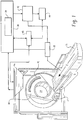
- a CT scanner 10 includes a rotating gantry 18 which rotates about the z-axis.
- the gantry 18 supports an x-ray source 12 such as an x-ray tube which generates a generally conical radiation beam.
- the gantry 18 also supports an x-ray sensitive detector 20 which subtends an angular arc on the opposite side of an examination region 14.
- the detector 20 is preferably a multi-slice detector which includes multiple rows or slices of detector elements extending in the z-direction and multiple columns of detector elements extending in the transverse direction.
- the detector 20 generates output signals indicative of radiation received along plurality of rays.
- Flat panel or other detector 20 configurations, as well as fourth generation or other system geometries, may also be implemented.
- An electrocardiogram (ECG) unit 28 generates data indicative of the cardiac phase of a patient undergoing examination.
- a patient support 16 such as a couch supports the patient in the examination region 14.
- the patient support 16 is preferably movable in the z-direction.
- a controller 28 coordinates the various scan parameters as necessary to carry out a desired scan protocol, including x-ray source 12 parameters such as tube voltage and current. Movement of the support 16 is preferably coordinated with rotation of the gantry so as generate a generally helical scan path.
- a reconstructor 30 reconstructs the stream of projection data to generate volumetric data indicative of the interior anatomy of the patient.
- the reconstructor 30 includes an image layer reconstructor 34 which reconstructs a plurality of image segments or layers.
- An interactive weighting processor 42 processes the volumetric image data generated by the reconstructor 30 for display in human readable form.
- a general purpose computer serves an operator console 44
- the console 44 includes a human readable output device such as a monitor or display and an input device such as a keyboard and mouse.
- the console 44 also includes program and data memory, including a relatively larger but lower speed disc memory and a relatively smaller, but relatively faster, random access memory (RAM).
- Software resident on the console allows the operator to control the operation of the scanner 10 by establishing desired scan protocols, initiating and terminating scans, viewing and otherwise manipulating the volumetric image data, and otherwise interacting with the scanner 10.
- the interactive weighting processor 42 and the operator console may be implemented in the same general purpose computer.
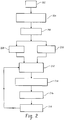
- Figure 2 depicts steps in a visualization technique which may be carried out using the scanner 10 and which is particularly well suited for the interactive visualization of periodically moving objects such as the coronary arteries of the heart.
- a CT scan of the patient is obtained.
- the patient's electrocardiogram (ECG) data is recorded along with the projection data.
- the reconstructor 30 reconstructs the projection data to generate volumetric data indicative of a volume or region of interest of the patient, for example a region which includes the heart.
- the ECG data is advantageously used to perform a retrospectively gated reconstruction at a desired phase of the patient's cardiac motion.
- the reconstruction parameters may be established to generate images relatively quickly, albeit of a relatively lower quality. Alternately, the reconstruction parameters may be established to generate relatively higher, diagnostic quality data.
- the reconstruction is performed using the ECR method, although other suitable reconstruction techniques may be used.
- one more human readable images indicative of the volumetric data are displayed on the operator console 44.
- a region which includes the heart is presented as one or more 3D rendered images.
- the user selects a sub-region of interest.
- the user would ordinarily select sub-region of interest which contains one or more coronary arteries to be visualized in greater detail.
- the maximum size of the sub-region selected by the user is preferably limited.
- the number of image layers NS to be backprojected can be estimated as follows: NS ⁇ ST TS where ST is the scan time and TS is the time shift between the projection segments that are used to generate successive image layers.
- the size of the sub-region and the number of image layers are preferably established according to the relationship: NS ⁇ Nvoxels ⁇ Svoxel ⁇ Smem where Nvoxels is the number of voxels in the sub-region, Svoxels is the number of bytes used to represent the value of each voxel in the sub-region, and Smem is the size of the console's RAM memory.
- Nvoxels is the number of voxels in the sub-region
- Svoxels is the number of bytes used to represent the value of each voxel in the sub-region
- Smem is the size of the console's RAM memory.
- TS milliseconds
- S milliseconds
- TS milliseconds
- a typical scan time of about 8 seconds (S) will thus result in about 400 image layers.
- Svoxel is typically 4. Consequently, limiting the size of the sub-region to the range of 10 6 voxels (i.e., in the range 64x64x64 voxels), which is reasonable for imaging of the coronary arteries, requires a RAM memory of about 1.6GB.
- such a memory requirement is substantially less than would be required where the region of interest includes the entire image layer, which would typically be in the range of 10 8 voxels (e.g., 512x 512x512 voxels), and is within the range of RAM memory available for a typical computer.
- the image layer weights are calculated for a desired cardiac phase.
- the image layers are accumulated or added according to the calculated weighting so as to generate volumetric image data indicative of the sub-region of interest at the desired cardiac phase. If the sub-region of interest for each of the desired image layers was not loaded into RAM memory prior to the calculation of the image weights 212, the information is loaded into RAM memory prior to the processing of the image layers.
- the volumetric image data indicative of the sub-region of interest at the desired phase is displayed in human readable form on the console 44 for review and/or further manipulation by the user.
- the user may at step 218 select a different phase for review, and processing returns to step 212.
- a particular advantage to the foregoing arrangement is that, by storing only the sub-regions of interest of the various image layers in RAM, and by further avoiding backprojecting the volume with each change in cardiac phase, the processing of the image layers may ordinarily be performed substantially instantaneously from the viewpoint of a human user. Consequently, the phase selection and resultant visualization may be performed interactively.
- the projection data includes projection data 302 1 ... 302 n acquired at each of a plurality of positions about a generally helical scan trajectory 304.
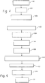
- a fan beam to parallel beam rebinning is applied to the projection data 302 so as to generate a plurality of sets of projection data segments 306 1 ... 306 m containing equidistant parallel projections.
- Each projection data segment 306 is characterised by a starting angular position ⁇ m start and an angular length ⁇ selected as described above. Note that the adjacent data segments 306 are partially overlapped to facilitate transition weighting between successive image layers.
- the respective projection data segments 306 1 ... 306 m are weighted, convolved with a ramp filter, and backprojected to generate image layers 308 1 ... 308 m .
- Each layer is characterized by a starting angular position ⁇ m start and an angular displacement ⁇ corresponding to that of its respective projection data segment 306.
- each image layer 308 is angularly weighted according to a generally trapezoidal weighting function.
- the angular overlap and transition weighting is advantageously selected so that the sum of the weighting applied to adjacent image layers remains constant in the overlap regions 312.
- the weighted image layers are then summed so as to generate the volumetric image data indicative of the sub-region of interest.
- the summing is preferably limited to those image segments 308 which provide a complete CT data set (e.g., when combined, having an angular length of approximately ⁇ ).
- the summation may also be performed over image segments 308 obtained at approximately the same point in multiple cardiac cycle.
- a particular advantage of the foregoing technique is that changing the desired phase requires a shifting along the image segments 308 which are accumulated to form the volumetric data. Compared to temporal rebinning of the projection data, such a technique avoids the necessity of performing a computationally expensive backprojection for each user-selected cardiac phase.
- limiting image layers to sub-regions of a size which can be loaded into the relatively higher speed RAM memory of the console 44 facilitates the interactive visualization of different cardiac phases.
- the objective is to weight the image layers so that the projection-dependent weight profiles of each voxel within the sub-region of interest, obtained by taking into account the weight of each image layer and the weights of the projections used to construct each image layer, approximate those of a reference weighting function which can be readily calculated for an arbitrary phase point. As described below, this may be accomplished by weighting the image layers so as to approximate the weighting which would be obtained using the ECR method.
- the patient's ECG is shown schematically at 502 for approximately three (3) cardiac cycles; an arbitrarily selected phase point of interest 504 is depicted in each of the cycles at 504 1 , 504 2 , 504 3 .
- a cardiac weighting function 506 is generated.
- the cardiac weighting function selects the projection data which corresponds temporally to the desired phase point 504.
- a cos 2 weighting function is generated.
- Such a weighting function applies relatively larger weights to rays which are temporally near to the phase point and reaches zero at the gating window boundaries.
- an illumination weighting 508 is generated.
- the illumination window for a given voxel 510 is a function of the acquisition geometry and is characterized by angular positions ⁇ 1' and ⁇ 1 which define the respective first and last projection angles at which the voxel is illuminated.
- the illumination window may be calculated numerically for each voxel in the reconstruction volume.
- a trapezoidal weighting function is generated.
- the angular range defined by the illumination window determines the amount of redundant data available for each voxel in the reconstruction volume. The resulting multiple coverage within the illumination window is used in the cardiac weighting.
- the cardiac 506 and illumination 508 weighting functions are multiplied to generate a combined weighting function 510.
- the combined weighting function is 510 is normalized to generate a normalized weighting function 512 for each voxel or for blocks or groups of voxels. More particularly, the weighting functions are normalized with respect to all different ⁇ partners. In the context of the ECR method, the normalized weighting function 512 would ordinarily be applied in the course of the backprojection. As described below, however, the normalized weighting function serves as a reference function which is used to calculate the weighting of the image layers.
- step 610 the image layers 308 which were generated only from projections which illuminate the voxel are identified.
- the weights for the identified image layers are calculated. More particularly, image layer weights are calculated to minimize the difference between the projection dependent weight profile of each voxel and the normalized weighting function 512 for that voxel. This may be accomplished by using a non-iterative closed-formula to calculate the difference, for example by minimizing the l 2 Hilbert space norm of the projection dependent difference
- negative image layer weights are truncated to zero.
- the image layer weights are normalized at step 616. More particularly, the image weights are normalized so that the sum of the weights for layers shifted in the acquisition stream by multiples of ⁇ are equal to unity, or otherwise to a common value. Performing this normalization and selecting an angular displacement between successive image layers which divides well into the time of one-half of a gantry rotation insures that the sum of the weights given for all the projections used to reconstruct the voxel in the final image and belong to the same angle between 0 and ⁇ will also equal unity. As is also known from the ECR method, the calculation of the image weights can be completed more quickly by calculating weights for regions or blocks of voxels, rather than calculating individual weights for each voxel.
- phase points 504 are shown as being at the same point in the cardiac cycle 502.
- the quality of the reconstructed image can be sensitive to variations in heart rate. Accordingly, the precise locations of the phase points 504 1 , 504 2 , 504 3 within their respective cardiac cycles may be individually modified prior to calculation of the calculation of the temporal weighting function 506.
- the user may be afforded to the opportunity to adjust one or more of the phase points 504 1 , 504 2 , 504 3 relative to the cardiac cycle in a desired amount.
- the weighting functions are updated accordingly, and the updated images are generated and displayed interactively.
- the weighting function may be adjusted in a substantially continuous fashion, the user is provided with additional flexibility to reduce the effects of perturbations in the cardiac cycle, which is further facilitated by the interactive nature of the process.
- such an arrangement facilitates the interactive optimization of image quality by allowing the user to interactively view the results of the modification and apply further modifications as desired.
Landscapes
- Physics & Mathematics (AREA)
- General Physics & Mathematics (AREA)
- Engineering & Computer Science (AREA)
- Theoretical Computer Science (AREA)
- Apparatus For Radiation Diagnosis (AREA)
- Image Processing (AREA)
Description
- The present invention relates to computed tomography (CT) imaging. It finds application to cardiac and other applications where it is desirable to improve the visualization of moving structures.
- Recent developments in CT technology, such as increased gantry rotation speeds and the introduction and acceptance of multi-slice scanners, have opened new applications for CT imaging. One such application is that of cardiac imaging, and more particularly the visualization of the coronary arteries.
- One particularly challenging aspect of cardiac imaging is obtaining volumetric data with the temporal resolution needed to effectively visualize the beating heart. See, e.g., Blobel, et al., Optimization of Temporal and Spatial Resolution for Cardiac CT Diagnostics (2004); Shoepf, et al., CT of Coronary Artery Disease, Radiology 2004: 232:18-32 (2004).
- One technique for performing gated cardiac reconstruction is the extended cardiac reconstruction (ECR) method. See Grass, et al., Helical Cardiac Cone Beam Reconstruction Using Retrospective ECG Gating, Phys. Med. Biol. 48 (2003) 3069-3084. The ECR method is an approximate helical cone beam reconstruction method based on 3D filtered backprojection. Within this framework, a retrospective cardiac gating scheme restricts the temporal information to a certain cardiac motion state of interest. Redundancy of the data is achieved using a low pitch helical reconstruction mode.
- More particularly, the ECR technique is based on the wedge method for helical cone beam reconstruction, which applies fan beam to parallel beam rebinning prior to cosine weighting, filtering and 3D back projection of the cone beam data. In addition to the geometric weighting factors inherent in the reconstruction geometry, the ECR method also includes a weighting function based on an illumination window, which is a result of the acquisition geometry. The method also includes a cardiac weighting function which is used to determine the part of the projection data in the temporal domain which is used to reconstruct an image volume image for a desired cardiac phase. Prior to back projection, the illumination weighting function and the cardiac weighting function are combined for each voxel in the volume using a normalization approach.
- While an effective cardiac reconstruction technique, the ECR method has required a new backprojection for each cardiac phase to be visualized. As the backprojection step is computationally expensive, the ECR method is not well suited to applications where relatively rapid, interactive visualization of volumetric data at a plurality of cardiac phases is desired.
- In another technique, the stream of acquisition data has been subdivided into data segments having an angular extent less than that required to form a complete tomographic data set. The data segments are in turn reconstructed to form a stream of segment images. Temporal rebinning has then been applied to the image data, which are then added to form the volumetric data. See Bruder, et al., Dynamic Cardiac CT Imaging Using Detectors with Large Cone Angle, Fully 3D Image Reconstruction in Radiology and Nuclear Medicine (2005).
- While this approach has avoided the need to recalculate the image volume for each user selected cardiac phase, the cardiac phase can only be adjusted within a discrete temporal grid, which is a function of the angular extent of the image segments. Moreover, adding the segment images to obtain a full volumetric image of the heart at the re-selected phase has required a large amount of writing to the hard disc of the computer. Consequently, the technique does not allow the rapid, interactive visualization of the volumetric data at an arbitrary cardiac phase.
- The following documents, relating to cardiac cone-beam CT, disclose the use of cardiac motion phase weighting techniques :
- NIELSEN T ET AL: "Cardiac cone-beam CT volume reconstruction using ART", MEDICAL PHYSICS, AIP, MELVILLE, NY, US, vol. 32, no. 4, 16 March 2005 (2005-03-16), pages 851-860, XP012075306, ISSN: 0094-2405, and
- GRASS M ET AL: "Artifact Analysis and Reconstruction Improvement in Helical Cardiac Cone Beam CT", IEEE TRANSACTIONS ON MEDICAL IMAGING, IEEE SERVICE CENTER, PISCATAWAY, NJ, US, vol. 23, no. 9, September 2004 (2004-09), pages 1150-1164, XP011117920, ISSN: 0278-0062
- Aspects of the present invention address these matters, and others.
- The invention is set out in the independent claims. Further advantageous embodiments are set out in the dependent claims.
- According to a first aspect of the present invention, a method includes using projection data acquired during a tomographic examination of a periodically moving object to reconstruct a plurality of image layers, combining the image layers to generate first image data indicative of the object at an arbitrary first motion phase, and displaying a human readable image indicative of the first image data. The image layers are generated from projection data segments having an angular extent less than that which is required to provide a complete tomographic data set.
- According to another aspect of the invention, an apparatus includes means for using projection data acquired during a tomographic examination of a periodically moving object to reconstruct a plurality of image layers, means for combining the image layers to generate first image data indicative of the object at an arbitrary first motion phase, and means for displaying a human readable image indicative of the first image data. The image layers are generated from projection data segments having an angular extent less than that which is required to provide a complete tomographic data set.
- In an embodiment the method includes using projection data acquired during a CT examination of a periodically moving object to reconstruct a plurality of image layers, combining the image layers according to a first weighting function to generate first image data indicative of the object at a first motion phase, displaying a human readable image indicative of the first image data, combining the image layers according to a second weighting function so as to generate second image data indicative of the object at a second motion phase, and generating a human readable image indicative of the object at the second motion phase. The image layers are generated from a plurality of angularly displaced projection data segments. The image layers are also displaced by a first angular displacement and the first and second motion phases are separated by an angular distance which is less than the first angular displacement.
- According to another aspect, a computer readable storage medium carries instructions which, when executed by a computer, cause the computer to carry out a method including the steps of using projection data acquired during a tomographic examination of a periodically moving object to generate a plurality of image layers, generating a first angularly varying reference weighting function, weighting the image layers so that the weighting applied to the image layers approximates the first weighting function, combining the weighted image layers to generate first volumetric data indicative of the object, and generating a human readable image indicative of the first volumetric data.
- In an embodiment of the computer readable storage medium the method includes generating a second angularly varying reference weighting function, weighting the image layers so that the weighting applied to the image layers approximates the second reference weighting function and combining the weighted image layers to generate second volumetric data indicative of the object. In a further embodiment the first reference function corresponds to a first phase of the periodic motion and the second reference function corresponds to a second phase of the periodic motion. In a still further embodiment the object is a beating heart and the phases are cardiac phases.
- In an embodiment of the computer readable storage medium the combining includes combining image layers having a total angular length of approximately π.
- In an embodiment of computer readable storage medium generating the first reference weighting function includes generating a temporal weighting function and generating an illumination window for each of a plurality of regions in a reconstruction volume. In a preferred embodiment the regions are voxels.
- In an embodiment of the computer readable storage medium the method includes calculating image layer weights which minimize the difference between a projection dependent weight profile and the first reference weighting function for a plurality regions in an image volume, wherein weighting the image layers includes weighting the image layer according to the calculated weights. In a preferred embodiment the method includes using a non-iterative closed formula to calculate the image layer weights.
- In an embodiment of the computer readable storage medium the method includes reconstructing the projection data to generate third volumetric data of a region of interest and selecting a sub-region of interest in the third volumetric data; wherein the partial image layers correspond to the sub-region of interest.
- Still other advantages and benefits will be appreciated by those skilled in the art upon reading and understanding the appended description.
-
Figure 1 depicts a CT scanner. -
Figure 2 depicts steps in an interactive visualization technique. -
Figures 3A, 3B , and3C depicts aspects of a technique for generating image layers. -
Figure 4 depicts steps in generating image layers. -
Figure 5 depicts aspects of a technique for generating an image layer weighting function. -
Figure 6 depicts steps in generating an image layer weighting function. - With reference to
Figure 1 , a CT scanner 10 includes arotating gantry 18 which rotates about the z-axis. Thegantry 18 supports anx-ray source 12 such as an x-ray tube which generates a generally conical radiation beam. Thegantry 18 also supports an x-raysensitive detector 20 which subtends an angular arc on the opposite side of anexamination region 14. Thedetector 20 is preferably a multi-slice detector which includes multiple rows or slices of detector elements extending in the z-direction and multiple columns of detector elements extending in the transverse direction. Thedetector 20 generates output signals indicative of radiation received along plurality of rays. Flat panel orother detector 20 configurations, as well as fourth generation or other system geometries, may also be implemented. - An electrocardiogram (ECG)
unit 28 generates data indicative of the cardiac phase of a patient undergoing examination. - A patient support 16 such as a couch supports the patient in the
examination region 14. Thepatient support 16 is preferably movable in the z-direction. Acontroller 28 coordinates the various scan parameters as necessary to carry out a desired scan protocol, includingx-ray source 12 parameters such as tube voltage and current. Movement of thesupport 16 is preferably coordinated with rotation of the gantry so as generate a generally helical scan path. - A
reconstructor 30 reconstructs the stream of projection data to generate volumetric data indicative of the interior anatomy of the patient. As will be described more fully below, thereconstructor 30 includes animage layer reconstructor 34 which reconstructs a plurality of image segments or layers. - An
interactive weighting processor 42 processes the volumetric image data generated by thereconstructor 30 for display in human readable form. - A general purpose computer serves an
operator console 44, Theconsole 44 includes a human readable output device such as a monitor or display and an input device such as a keyboard and mouse. Theconsole 44 also includes program and data memory, including a relatively larger but lower speed disc memory and a relatively smaller, but relatively faster, random access memory (RAM). Software resident on the console allows the operator to control the operation of the scanner 10 by establishing desired scan protocols, initiating and terminating scans, viewing and otherwise manipulating the volumetric image data, and otherwise interacting with the scanner 10. Note that theinteractive weighting processor 42 and the operator console may be implemented in the same general purpose computer. -
Figure 2 depicts steps in a visualization technique which may be carried out using the scanner 10 and which is particularly well suited for the interactive visualization of periodically moving objects such as the coronary arteries of the heart. - At
step 202, a CT scan of the patient is obtained. The patient's electrocardiogram (ECG) data is recorded along with the projection data. - At
step 204, thereconstructor 30 reconstructs the projection data to generate volumetric data indicative of a volume or region of interest of the patient, for example a region which includes the heart. The ECG data is advantageously used to perform a retrospectively gated reconstruction at a desired phase of the patient's cardiac motion. As the volumetric data will be used in a subsequent step to identify a sub-region of interest, the reconstruction parameters may be established to generate images relatively quickly, albeit of a relatively lower quality. Alternately, the reconstruction parameters may be established to generate relatively higher, diagnostic quality data. In one implementation, the reconstruction is performed using the ECR method, although other suitable reconstruction techniques may be used. - At
step 206, one more human readable images indicative of the volumetric data are displayed on theoperator console 44. In one implementation, a region which includes the heart is presented as one or more 3D rendered images. - At
step 208, the user selects a sub-region of interest. In the cardiac example, the user would ordinarily select sub-region of interest which contains one or more coronary arteries to be visualized in greater detail. As will be described more fully below, the maximum size of the sub-region selected by the user is preferably limited. - At
step 210, theimage layer reconstructor 34 performs a non-gated reconstruction of the projection data into a plurality of image segments or layers. More particularly, the projection data acquired during each rotation along the spiral path is divided in a plurality of projection segments having an angular displacement Δθ :
- The number of image layers NS to be backprojected can be estimated as follows:

- The size of the sub-region and the number of image layers are preferably established according to the relationship:

console 44. As compared to situations in which some or all of the image layers are stored in theconsole 44 disc memory, such an arrangement will ordinarily allow the image layers to be processed much more quickly, if not substantially instantaneously from the perspective of a human user. - As one example, setting TS less than about 20 milliseconds (mS) can be expected to yield acceptable image quality in cardiac applications. A typical scan time of about 8 seconds (S) will thus result in about 400 image layers. Where the voxel values are stored as single precision floating point numbers, Svoxel is typically 4. Consequently, limiting the size of the sub-region to the range of 106 voxels (i.e., in the range 64x64x64 voxels), which is reasonable for imaging of the coronary arteries, requires a RAM memory of about 1.6GB. As will be appreciated, such a memory requirement is substantially less than would be required where the region of interest includes the entire image layer, which would typically be in the range of 108 voxels (e.g., 512x 512x512 voxels), and is within the range of RAM memory available for a typical computer.
- At
step 212, and as will also be described further below, the image layer weights are calculated for a desired cardiac phase. - At
step 214, the image layers are accumulated or added according to the calculated weighting so as to generate volumetric image data indicative of the sub-region of interest at the desired cardiac phase. If the sub-region of interest for each of the desired image layers was not loaded into RAM memory prior to the calculation of theimage weights 212, the information is loaded into RAM memory prior to the processing of the image layers. - At
step 216, the volumetric image data indicative of the sub-region of interest at the desired phase is displayed in human readable form on theconsole 44 for review and/or further manipulation by the user. - If desired, the user may at
step 218 select a different phase for review, and processing returns to step 212. A particular advantage to the foregoing arrangement is that, by storing only the sub-regions of interest of the various image layers in RAM, and by further avoiding backprojecting the volume with each change in cardiac phase, the processing of the image layers may ordinarily be performed substantially instantaneously from the viewpoint of a human user. Consequently, the phase selection and resultant visualization may be performed interactively. - One technique for generating and weighting the image layers according to the wedge method will now be described in relation to
Figures 3 and4 . With reference toFigure 3A , the projection data includesprojection data 3021 ... 302n acquired at each of a plurality of positions about a generallyhelical scan trajectory 304. - At 402, and with reference to
Figure 3B , a fan beam to parallel beam rebinning is applied to theprojection data 302 so as to generate a plurality of sets ofprojection data segments 3061 ... 306m containing equidistant parallel projections. Eachprojection data segment 306 is characterised by a starting angular position
adjacent data segments 306 are partially overlapped to facilitate transition weighting between successive image layers. - At 404, and with reference to
Figure 3C , the respectiveprojection data segments 3061 ... 306m are weighted, convolved with a ramp filter, and backprojected to generateimage layers 3081 ... 308m. Each layer is characterized by a starting angular position
projection data segment 306. - As shown, each
image layer 308 is angularly weighted according to a generally trapezoidal weighting function. The angular overlap and transition weighting is advantageously selected so that the sum of the weighting applied to adjacent image layers remains constant in theoverlap regions 312. - At 406, the weighted image layers are then summed so as to generate the volumetric image data indicative of the sub-region of interest. Note that, in order to maximize the temporal resolution in a generated image, the summing is preferably limited to those
image segments 308 which provide a complete CT data set (e.g., when combined, having an angular length of approximately π). The summation may also be performed overimage segments 308 obtained at approximately the same point in multiple cardiac cycle. A particular advantage of the foregoing technique is that changing the desired phase requires a shifting along theimage segments 308 which are accumulated to form the volumetric data. Compared to temporal rebinning of the projection data, such a technique avoids the necessity of performing a computationally expensive backprojection for each user-selected cardiac phase. Moreover, limiting image layers to sub-regions of a size which can be loaded into the relatively higher speed RAM memory of theconsole 44 facilitates the interactive visualization of different cardiac phases. - One drawback to the above technique, however, is that the cardiac phase can be shifted only in angular increments of Δθ (or stated another way, in the corresponding temporal increment). A technique which provides additional flexibility in selecting the phase will now be described in relation to
Figures 5 and6 . The objective is to weight the image layers so that the projection-dependent weight profiles of each voxel within the sub-region of interest, obtained by taking into account the weight of each image layer and the weights of the projections used to construct each image layer, approximate those of a reference weighting function which can be readily calculated for an arbitrary phase point. As described below, this may be accomplished by weighting the image layers so as to approximate the weighting which would be obtained using the ECR method. - The patient's ECG is shown schematically at 502 for approximately three (3) cardiac cycles; an arbitrarily selected phase point of
interest 504 is depicted in each of the cycles at 5041, 5042, 5043. - At
step 602, acardiac weighting function 506 is generated. The cardiac weighting function selects the projection data which corresponds temporally to the desiredphase point 504. In one implementation, a cos2 weighting function is generated. Such a weighting function applies relatively larger weights to rays which are temporally near to the phase point and reaches zero at the gating window boundaries. - At
step 604, anillumination weighting 508 is generated. The illumination window for a givenvoxel 510 is a function of the acquisition geometry and is characterized by angular positions θ1' and θ1 which define the respective first and last projection angles at which the voxel is illuminated. The illumination window may be calculated numerically for each voxel in the reconstruction volume. In one implementation, a trapezoidal weighting function is generated. The angular range defined by the illumination window determines the amount of redundant data available for each voxel in the reconstruction volume. The resulting multiple coverage within the illumination window is used in the cardiac weighting. - At 606, the cardiac 506 and
illumination 508 weighting functions are multiplied to generate a combinedweighting function 510. - At 608, the combined weighting function is 510 is normalized to generate a normalized
weighting function 512 for each voxel or for blocks or groups of voxels. More particularly, the weighting functions are normalized with respect to all different π partners. In the context of the ECR method, the normalizedweighting function 512 would ordinarily be applied in the course of the backprojection. As described below, however, the normalized weighting function serves as a reference function which is used to calculate the weighting of the image layers. - At
step 610, the image layers 308 which were generated only from projections which illuminate the voxel are identified. - At
step 612, the weights for the identified image layers are calculated. More particularly, image layer weights are calculated to minimize the difference between the projection dependent weight profile of each voxel and the normalizedweighting function 512 for that voxel. This may be accomplished by using a non-iterative closed-formula to calculate the difference, for example by minimizing the l2 Hilbert space norm of the projection dependent difference - At
step 614, negative image layer weights are truncated to zero. - The image layer weights are normalized at
step 616. More particularly, the image weights are normalized so that the sum of the weights for layers shifted in the acquisition stream by multiples of π are equal to unity, or otherwise to a common value. Performing this normalization and selecting an angular displacement between successive image layers which divides well into the time of one-half of a gantry rotation insures that the sum of the weights given for all the projections used to reconstruct the voxel in the final image and belong to the same angle between 0 and π will also equal unity. As is also known from the ECR method, the calculation of the image weights can be completed more quickly by calculating weights for regions or blocks of voxels, rather than calculating individual weights for each voxel. - Other variations are possible. As depicted in
Figure 4 , the phase points 504 are shown as being at the same point in thecardiac cycle 502. However, the quality of the reconstructed image can be sensitive to variations in heart rate. Accordingly, the precise locations of the phase points 5041, 5042, 5043 within their respective cardiac cycles may be individually modified prior to calculation of the calculation of thetemporal weighting function 506. - Thus, the user may be afforded to the opportunity to adjust one or more of the phase points 5041, 5042, 5043 relative to the cardiac cycle in a desired amount. The weighting functions are updated accordingly, and the updated images are generated and displayed interactively. As the weighting function may be adjusted in a substantially continuous fashion, the user is provided with additional flexibility to reduce the effects of perturbations in the cardiac cycle, which is further facilitated by the interactive nature of the process. As will be appreciated, such an arrangement facilitates the interactive optimization of image quality by allowing the user to interactively view the results of the modification and apply further modifications as desired.
- While the foregoing has been described in connection with approximating reference functions which would be obtained using the ECR method, other desired reference weighting functions may also be used.
- The invention has been described with reference to the preferred embodiments. Of course, modifications and alterations will occur to others upon reading and understanding the preceding description. It is intended that the invention be construed as including all such modifications and alterations insofar as they come within the scope of the appended claims.
Claims (13)
- A method comprising:a) using projection data (302) acquired during a tomographic examination of a periodically moving object to reconstruct a plurality of image layers (308), wherein the image layers are generated from projection data segments (306) having an angular extent less than that which is required to provide a complete tomographic data set;b) generating a first reference weighting function (512) which corresponds to a first motion phase of said periodically moving object;c) calculating image layer weights which minimize the difference between a projection dependent weight profile and the first reference weighting function for each of a plurality of regions in an image volume;d) weighting the image layers by means of the calculated image layer weights so that the weighting applied to the image layers approximates the first reference weighting function;e) combining the image layers to generate first image data indicative of the object at the first motion phase;f) displaying a human readable image indicative of the first image data.
- The method of claim 1 including:receiving an input from a human user indicative of an arbitrary second motion phase;performing steps b) to f) for the second motion phase.
- The method of claim 2 wherein the image layers are displaced by a first angular displacement and the first and second motion phases are separated by an angular distance which is less than the first angular displacement.
- The method of claim 1 wherein combining includes combining image layers generated from projection data having a total angular length of approximately π.
- The method of claim 1 wherein generating the first weighting function includes
generating a temporally varying weighting function (506); generating an illumination window (508). - The method of claim 1 including
reconstructing the projection data to generate third image data of a region of interest;
selecting a sub-region of interest in the third volumetric data; wherein the image layers correspond to the sub-region of interest. - The method of claim 1 wherein the first motion phase is established at a plurality of cycles of the object motion and including
independently adjusting a phase point (5041) in at least one of the cycles;
combining the image layers to generate fourth image data indicative of the object. - The method of claim 3, wherein the projection data is aquired during a CT examination.
- The method of claim 8 including:generating a cardiac weighting function (506) for the first motion phase;generating an illumination weighting function (508);combining the cardiac and illumination weighting functions to generate a combined weighting function (510);normalizing the combined weighting function to generate a normalized weighting function (512).
- The method of claim 8 wherein the first weighting function weights the image layers so that the projection dependent weight profiles of a plurality of regions within an image region approximate those of a reference weighting function.
- The method of claim 8 including
reconstructing the projection data to generate image data indicative of a region of interest of the object;
displaying the image data in human readable form;
receiving an input from human user indicative of a sub-region of interest of the object;
wherein the step of using projection data is performed temporally in parallel with the step of receiving an input. - An apparatus comprising:means for using projection data (302) acquired during a tomographic examination of a periodically moving object to reconstruct a plurality of image layers (308), wherein the image layers are generated from projection data segments (306) having an angular extent less than that which is required to provide a complete tomographic data set;means for generating a first reference weighting function (512) which corresponds to a first motion phase of said periodically moving object;means for calculating image layer weights which minimize the difference between a projection dependent weight profile and the first reference weighting function for each of a plurality of regions in an image volume;means for weighting the image layers by means of the calculated image layer weights so that the weighting applied to the image layers approximates the first reference weighting function;means for combining the image layers to generate first image data indicative of the object at the first motion phase;means for displaying a human readable image indicative of the first image data.
- A computer readable storage medium which carries instructions which, when executed by a computer, cause the computer to carry out the steps of the method of claim 1.
Applications Claiming Priority (2)
| Application Number | Priority Date | Filing Date | Title |
|---|---|---|---|
| US80326006P | 2006-05-26 | 2006-05-26 | |
| PCT/US2007/068539 WO2007140094A2 (en) | 2006-05-26 | 2007-05-09 | Dynamic computed tomography imaging |
Publications (2)
| Publication Number | Publication Date |
|---|---|
| EP2030170A2 EP2030170A2 (en) | 2009-03-04 |
| EP2030170B1 true EP2030170B1 (en) | 2019-01-16 |
Family
ID=38626439
Family Applications (1)
| Application Number | Title | Priority Date | Filing Date |
|---|---|---|---|
| EP07762040.9A Not-in-force EP2030170B1 (en) | 2006-05-26 | 2007-05-09 | Dynamic computed tomography imaging |
Country Status (6)
| Country | Link |
|---|---|
| US (1) | US8279997B2 (en) |
| EP (1) | EP2030170B1 (en) |
| JP (1) | JP2009538205A (en) |
| CN (1) | CN101454804B (en) |
| RU (1) | RU2441587C2 (en) |
| WO (1) | WO2007140094A2 (en) |
Cited By (1)
| Publication number | Priority date | Publication date | Assignee | Title |
|---|---|---|---|---|
| US10786212B1 (en) | 2019-05-31 | 2020-09-29 | MinFound Medical Systems Co., Ltd. | System and method of helical cardiac cone beam reconstruction |
Families Citing this family (12)
| Publication number | Priority date | Publication date | Assignee | Title |
|---|---|---|---|---|
| US9814431B2 (en) * | 2007-05-04 | 2017-11-14 | Memorial Sloan Kettering Cancer Center | Methods and systems for retrospective internal gating |
| US8712134B2 (en) * | 2011-10-18 | 2014-04-29 | Kabushiki Kaisha Toshiba | Method and system for expanding axial coverage in iterative reconstruction in computer tomography (CT) |
| US8885907B2 (en) * | 2011-11-07 | 2014-11-11 | The Texas A&M University System | Emission computed tomography for guidance of sampling and therapeutic delivery |
| WO2013145831A1 (en) * | 2012-03-27 | 2013-10-03 | 株式会社日立メディコ | Radiation image pick-up device and image processing method |
| EP2845024B1 (en) * | 2012-05-02 | 2019-04-10 | Koninklijke Philips N.V. | Thermometry imaging |
| US9767536B2 (en) | 2013-03-14 | 2017-09-19 | Memorial Sloan Kettering Cancer Center | Medical imaging |
| RU2544099C1 (en) * | 2014-02-11 | 2015-03-10 | Федеральное государственное бюджетное учреждение Дальневосточный научный центр физиологии и патологии дыхания Сибирского отделения Российской академии медицинских наук | Diagnostic technique in lung hyperinflation |
| WO2015125086A1 (en) * | 2014-02-18 | 2015-08-27 | Koninklijke Philips N.V. | In-reconstruction filtering for positron emission tomography(pet) list mode iterative reconstruction |
| CN104200500B (en) * | 2014-07-29 | 2017-06-06 | 沈阳东软医疗系统有限公司 | The method for reconstructing and device of a kind of cardiac image |
| CN106548464B (en) * | 2016-11-07 | 2019-04-02 | 赛诺联合医疗科技(北京)有限公司 | A method and apparatus for constructing a phase image |
| EP3574836A1 (en) * | 2018-05-30 | 2019-12-04 | Koninklijke Philips N.V. | Temporally gated three-dimensional imaging |
| CN112785552A (en) * | 2020-12-30 | 2021-05-11 | 深兰人工智能芯片研究院(江苏)有限公司 | Quality estimation method, quality estimation device, electronic device and storage medium |
Citations (2)
| Publication number | Priority date | Publication date | Assignee | Title |
|---|---|---|---|---|
| WO2002065398A1 (en) * | 2001-02-13 | 2002-08-22 | Koninklijke Philips Electronics Nv | Limited-angle frequency-distance resolution recovery in nuclear medicine imaging |
| US20050135555A1 (en) * | 2003-12-23 | 2005-06-23 | Claus Bernhard Erich H. | Method and system for simultaneously viewing rendered volumes |
Family Cites Families (27)
| Publication number | Priority date | Publication date | Assignee | Title |
|---|---|---|---|---|
| JP3510389B2 (en) * | 1995-07-10 | 2004-03-29 | ジーイー横河メディカルシステム株式会社 | X-ray CT system |
| JP4316017B2 (en) * | 1995-09-11 | 2009-08-19 | ジーイー横河メディカルシステム株式会社 | X-ray CT system |
| JP3124254B2 (en) * | 1997-07-24 | 2001-01-15 | ジーイー横河メディカルシステム株式会社 | Radiation tomography equipment |
| JP4698780B2 (en) * | 1998-09-15 | 2011-06-08 | シーメンス アクチエンゲゼルシヤフト | Image reconstruction method and measurement data acquisition method |
| US6243437B1 (en) * | 1998-11-25 | 2001-06-05 | General Electric Company | Coronary calcification detection using retrospective cardiac gating of imaging system |
| US6370217B1 (en) * | 1999-05-07 | 2002-04-09 | General Electric Company | Volumetric computed tomography system for cardiac imaging |
| US6639965B1 (en) * | 1999-09-30 | 2003-10-28 | General Electric Company | Methods and apparatus for cardiac imaging with conventional computed tomography |
| US6480560B2 (en) * | 2001-03-16 | 2002-11-12 | Ge Medical Systems Global Technology Company, Llc | Methods and apparatus for motion gating using CT projection data |
| DE10123798B4 (en) * | 2001-05-16 | 2007-04-19 | Siemens Ag | Method for computed tomography |
| US6718004B2 (en) * | 2001-06-28 | 2004-04-06 | General Electric Company | Methods and apparatus for coronary-specific imaging reconstruction |
| US6426990B1 (en) * | 2001-06-28 | 2002-07-30 | General Electric Company | Methods and apparatus for coronary-specific imaging reconstruction |
| DE10133237B4 (en) * | 2001-07-09 | 2007-04-19 | Siemens Ag | Method for computed tomography and computed tomography (CT) device |
| JP2003052688A (en) * | 2001-08-10 | 2003-02-25 | Ge Medical Systems Global Technology Co Llc | Image generation method and X-ray CT apparatus |
| JP2003164445A (en) * | 2001-11-26 | 2003-06-10 | Ge Medical Systems Global Technology Co Llc | Method and apparatus for coronary imaging |
| DE10162768A1 (en) * | 2001-12-20 | 2003-07-03 | Philips Intellectual Property | CT Scanner |
| FR2844080B1 (en) | 2002-08-27 | 2005-03-04 | Ge Med Sys Global Tech Co Llc | METHOD FOR IMPROVING THE VISUALIZATION OF A BLOOD VESSEL USING TECHNIQUE FOR RECONSTRUCTING SYNCHRONIZED IMAGES |
| DE10244180B4 (en) * | 2002-09-23 | 2009-08-27 | Siemens Ag | Method for imaging in computed tomography of a periodically moving examination subject and CT apparatus for performing the method |
| US6775346B2 (en) * | 2002-10-21 | 2004-08-10 | Koninklijke Philips Electronics N.V. | Conebeam computed tomography imaging |
| DE10251448A1 (en) * | 2002-11-05 | 2004-05-19 | Siemens Ag | CT method for imaging of a periodically moving examination area, especially the heart, whereby image segments are combined to form image planes, which are subsequently joined together to form a complete image |
| US6944263B2 (en) * | 2002-12-31 | 2005-09-13 | Tsinghua University | Apparatus and methods for multiple view angle stereoscopic radiography |
| DE10354214A1 (en) * | 2003-11-20 | 2005-06-02 | Siemens Ag | A method of generating tomographic slices of a periodically moving object having a plurality of focus-detector combinations |
| US7689261B2 (en) | 2003-11-26 | 2010-03-30 | General Electric Company | Cardiac display methods and apparatus |
| DE102004028121A1 (en) | 2004-06-09 | 2006-01-05 | Siemens Ag | A method of reconstructing sectional images of a cyclically and complexly moving examination object from detector measurement data of a tomography device |
| JP4771944B2 (en) * | 2004-06-16 | 2011-09-14 | 株式会社日立メディコ | Radiation tomographic imaging system |
| US7889901B2 (en) * | 2005-02-10 | 2011-02-15 | Koninklijke Philips Electronics N.V. | Computed tomography method with helical relative movement and conical beam bundle |
| EP1861825B1 (en) * | 2005-03-17 | 2008-10-08 | Philips Intellectual Property & Standards GmbH | Method and device for the iterative reconstruction of cardiac images |
| EP2238906B1 (en) * | 2005-09-07 | 2015-04-08 | Kabushiki Kaisha Toshiba | X-ray computed tomography apparatus |
-
2007
- 2007-05-09 RU RU2008151768/14A patent/RU2441587C2/en not_active IP Right Cessation
- 2007-05-09 CN CN2007800191755A patent/CN101454804B/en not_active Expired - Fee Related
- 2007-05-09 JP JP2009512212A patent/JP2009538205A/en active Pending
- 2007-05-09 US US12/302,108 patent/US8279997B2/en not_active Expired - Fee Related
- 2007-05-09 EP EP07762040.9A patent/EP2030170B1/en not_active Not-in-force
- 2007-05-09 WO PCT/US2007/068539 patent/WO2007140094A2/en not_active Ceased
Patent Citations (2)
| Publication number | Priority date | Publication date | Assignee | Title |
|---|---|---|---|---|
| WO2002065398A1 (en) * | 2001-02-13 | 2002-08-22 | Koninklijke Philips Electronics Nv | Limited-angle frequency-distance resolution recovery in nuclear medicine imaging |
| US20050135555A1 (en) * | 2003-12-23 | 2005-06-23 | Claus Bernhard Erich H. | Method and system for simultaneously viewing rendered volumes |
Cited By (1)
| Publication number | Priority date | Publication date | Assignee | Title |
|---|---|---|---|---|
| US10786212B1 (en) | 2019-05-31 | 2020-09-29 | MinFound Medical Systems Co., Ltd. | System and method of helical cardiac cone beam reconstruction |
Also Published As
| Publication number | Publication date |
|---|---|
| CN101454804A (en) | 2009-06-10 |
| WO2007140094A3 (en) | 2008-01-17 |
| US20090290774A1 (en) | 2009-11-26 |
| EP2030170A2 (en) | 2009-03-04 |
| US8279997B2 (en) | 2012-10-02 |
| WO2007140094A2 (en) | 2007-12-06 |
| RU2008151768A (en) | 2010-07-10 |
| CN101454804B (en) | 2013-05-01 |
| JP2009538205A (en) | 2009-11-05 |
| RU2441587C2 (en) | 2012-02-10 |
Similar Documents
| Publication | Publication Date | Title |
|---|---|---|
| US8279997B2 (en) | Dynamic computed tomography imaging | |
| CN1968654B (en) | Radiation tomography device | |
| KR102139668B1 (en) | Tomography apparatus and method for reconstructing a tomography image thereof | |
| US6466640B1 (en) | Computed tomography system and method | |
| CN100375122C (en) | Method and apparatus for deriving motion information from projection data | |
| CN102138806B (en) | Rebuild in the measurement field Computer computed tomography images of expansion | |
| JP2004160222A (en) | Computer tomography method and apparatus | |
| EP1372115B1 (en) | Methods and apparatus for reconstructing an image of an object | |
| EP1895906B1 (en) | Bands artifact reduction for cardiac ct imaging | |
| JP2007000408A (en) | X-ray CT system | |
| US6937689B2 (en) | Methods and apparatus for image reconstruction in distributed x-ray source CT systems | |
| JP2003164444A (en) | Row-by-row full spiral view weighting method and apparatus for CT scanner | |
| JP3917684B2 (en) | Method and apparatus for creating a tomographic image of an object | |
| US10089758B1 (en) | Volume image reconstruction using projection decomposition | |
| EP1615561B1 (en) | Computer tomography method for a periodically moving object | |
| JP2008519636A (en) | Computed tomography method for inspection of periodic moving objects | |
| US6999550B2 (en) | Method and apparatus for obtaining data for reconstructing images of an object | |
| EP1696796B1 (en) | Computer tomography method for objects moving periodically | |
| EP2076885B1 (en) | Imaging system, imaging method and computer program for imaging a region of interest | |
| Heverhagen | Physics of computed tomography scanning | |
| JPH07262350A (en) | Image display device | |
| Kachelriess | Principles, Design, and Operation of Multi-slice CT |
Legal Events
| Date | Code | Title | Description |
|---|---|---|---|
| PUAI | Public reference made under article 153(3) epc to a published international application that has entered the european phase |
Free format text: ORIGINAL CODE: 0009012 |
|
| 17P | Request for examination filed |
Effective date: 20081229 |
|
| AK | Designated contracting states |
Kind code of ref document: A2 Designated state(s): AT BE BG CH CY CZ DE DK EE ES FI FR GB GR HU IE IS IT LI LT LU LV MC MT NL PL PT RO SE SI SK TR |
|
| AX | Request for extension of the european patent |
Extension state: AL BA HR MK RS |
|
| DAX | Request for extension of the european patent (deleted) | ||
| RAP1 | Party data changed (applicant data changed or rights of an application transferred) |
Owner name: KONINKLIJKE PHILIPS N.V. |
|
| STAA | Information on the status of an ep patent application or granted ep patent |
Free format text: STATUS: EXAMINATION IS IN PROGRESS |
|
| 17Q | First examination report despatched |
Effective date: 20170609 |
|
| GRAP | Despatch of communication of intention to grant a patent |
Free format text: ORIGINAL CODE: EPIDOSNIGR1 |
|
| STAA | Information on the status of an ep patent application or granted ep patent |
Free format text: STATUS: GRANT OF PATENT IS INTENDED |
|
| INTG | Intention to grant announced |
Effective date: 20180813 |
|
| GRAS | Grant fee paid |
Free format text: ORIGINAL CODE: EPIDOSNIGR3 |
|
| GRAA | (expected) grant |
Free format text: ORIGINAL CODE: 0009210 |
|
| STAA | Information on the status of an ep patent application or granted ep patent |
Free format text: STATUS: THE PATENT HAS BEEN GRANTED |
|
| AK | Designated contracting states |
Kind code of ref document: B1 Designated state(s): AT BE BG CH CY CZ DE DK EE ES FI FR GB GR HU IE IS IT LI LT LU LV MC MT NL PL PT RO SE SI SK TR |
|
| REG | Reference to a national code |
Ref country code: GB Ref legal event code: FG4D |
|
| REG | Reference to a national code |
Ref country code: CH Ref legal event code: EP |
|
| REG | Reference to a national code |
Ref country code: IE Ref legal event code: FG4D |
|
| REG | Reference to a national code |
Ref country code: DE Ref legal event code: R096 Ref document number: 602007057442 Country of ref document: DE |
|
| REG | Reference to a national code |
Ref country code: AT Ref legal event code: REF Ref document number: 1090284 Country of ref document: AT Kind code of ref document: T Effective date: 20190215 |
|
| REG | Reference to a national code |
Ref country code: DE Ref legal event code: R084 Ref document number: 602007057442 Country of ref document: DE |
|
| REG | Reference to a national code |
Ref country code: GB Ref legal event code: 746 Effective date: 20190325 |
|
| REG | Reference to a national code |
Ref country code: NL Ref legal event code: MP Effective date: 20190116 |
|
| REG | Reference to a national code |
Ref country code: LT Ref legal event code: MG4D |
|
| PG25 | Lapsed in a contracting state [announced via postgrant information from national office to epo] |
Ref country code: NL Free format text: LAPSE BECAUSE OF FAILURE TO SUBMIT A TRANSLATION OF THE DESCRIPTION OR TO PAY THE FEE WITHIN THE PRESCRIBED TIME-LIMIT Effective date: 20190116 |
|
| REG | Reference to a national code |
Ref country code: AT Ref legal event code: MK05 Ref document number: 1090284 Country of ref document: AT Kind code of ref document: T Effective date: 20190116 |
|
| PG25 | Lapsed in a contracting state [announced via postgrant information from national office to epo] |
Ref country code: FI Free format text: LAPSE BECAUSE OF FAILURE TO SUBMIT A TRANSLATION OF THE DESCRIPTION OR TO PAY THE FEE WITHIN THE PRESCRIBED TIME-LIMIT Effective date: 20190116 Ref country code: PT Free format text: LAPSE BECAUSE OF FAILURE TO SUBMIT A TRANSLATION OF THE DESCRIPTION OR TO PAY THE FEE WITHIN THE PRESCRIBED TIME-LIMIT Effective date: 20190516 Ref country code: PL Free format text: LAPSE BECAUSE OF FAILURE TO SUBMIT A TRANSLATION OF THE DESCRIPTION OR TO PAY THE FEE WITHIN THE PRESCRIBED TIME-LIMIT Effective date: 20190116 Ref country code: SE Free format text: LAPSE BECAUSE OF FAILURE TO SUBMIT A TRANSLATION OF THE DESCRIPTION OR TO PAY THE FEE WITHIN THE PRESCRIBED TIME-LIMIT Effective date: 20190116 Ref country code: LT Free format text: LAPSE BECAUSE OF FAILURE TO SUBMIT A TRANSLATION OF THE DESCRIPTION OR TO PAY THE FEE WITHIN THE PRESCRIBED TIME-LIMIT Effective date: 20190116 Ref country code: ES Free format text: LAPSE BECAUSE OF FAILURE TO SUBMIT A TRANSLATION OF THE DESCRIPTION OR TO PAY THE FEE WITHIN THE PRESCRIBED TIME-LIMIT Effective date: 20190116 |
|
| PG25 | Lapsed in a contracting state [announced via postgrant information from national office to epo] |
Ref country code: BG Free format text: LAPSE BECAUSE OF FAILURE TO SUBMIT A TRANSLATION OF THE DESCRIPTION OR TO PAY THE FEE WITHIN THE PRESCRIBED TIME-LIMIT Effective date: 20190416 Ref country code: IS Free format text: LAPSE BECAUSE OF FAILURE TO SUBMIT A TRANSLATION OF THE DESCRIPTION OR TO PAY THE FEE WITHIN THE PRESCRIBED TIME-LIMIT Effective date: 20190516 Ref country code: LV Free format text: LAPSE BECAUSE OF FAILURE TO SUBMIT A TRANSLATION OF THE DESCRIPTION OR TO PAY THE FEE WITHIN THE PRESCRIBED TIME-LIMIT Effective date: 20190116 Ref country code: GR Free format text: LAPSE BECAUSE OF FAILURE TO SUBMIT A TRANSLATION OF THE DESCRIPTION OR TO PAY THE FEE WITHIN THE PRESCRIBED TIME-LIMIT Effective date: 20190417 |
|
| REG | Reference to a national code |
Ref country code: DE Ref legal event code: R097 Ref document number: 602007057442 Country of ref document: DE |
|
| PG25 | Lapsed in a contracting state [announced via postgrant information from national office to epo] |
Ref country code: EE Free format text: LAPSE BECAUSE OF FAILURE TO SUBMIT A TRANSLATION OF THE DESCRIPTION OR TO PAY THE FEE WITHIN THE PRESCRIBED TIME-LIMIT Effective date: 20190116 Ref country code: AT Free format text: LAPSE BECAUSE OF FAILURE TO SUBMIT A TRANSLATION OF THE DESCRIPTION OR TO PAY THE FEE WITHIN THE PRESCRIBED TIME-LIMIT Effective date: 20190116 Ref country code: IT Free format text: LAPSE BECAUSE OF FAILURE TO SUBMIT A TRANSLATION OF THE DESCRIPTION OR TO PAY THE FEE WITHIN THE PRESCRIBED TIME-LIMIT Effective date: 20190116 Ref country code: SK Free format text: LAPSE BECAUSE OF FAILURE TO SUBMIT A TRANSLATION OF THE DESCRIPTION OR TO PAY THE FEE WITHIN THE PRESCRIBED TIME-LIMIT Effective date: 20190116 Ref country code: DK Free format text: LAPSE BECAUSE OF FAILURE TO SUBMIT A TRANSLATION OF THE DESCRIPTION OR TO PAY THE FEE WITHIN THE PRESCRIBED TIME-LIMIT Effective date: 20190116 Ref country code: RO Free format text: LAPSE BECAUSE OF FAILURE TO SUBMIT A TRANSLATION OF THE DESCRIPTION OR TO PAY THE FEE WITHIN THE PRESCRIBED TIME-LIMIT Effective date: 20190116 Ref country code: CZ Free format text: LAPSE BECAUSE OF FAILURE TO SUBMIT A TRANSLATION OF THE DESCRIPTION OR TO PAY THE FEE WITHIN THE PRESCRIBED TIME-LIMIT Effective date: 20190116 |
|
| PLBE | No opposition filed within time limit |
Free format text: ORIGINAL CODE: 0009261 |
|
| STAA | Information on the status of an ep patent application or granted ep patent |
Free format text: STATUS: NO OPPOSITION FILED WITHIN TIME LIMIT |
|
| 26N | No opposition filed |
Effective date: 20191017 |
|
| REG | Reference to a national code |
Ref country code: CH Ref legal event code: PL |
|
| PG25 | Lapsed in a contracting state [announced via postgrant information from national office to epo] |
Ref country code: CH Free format text: LAPSE BECAUSE OF NON-PAYMENT OF DUE FEES Effective date: 20190531 Ref country code: LI Free format text: LAPSE BECAUSE OF NON-PAYMENT OF DUE FEES Effective date: 20190531 Ref country code: MC Free format text: LAPSE BECAUSE OF FAILURE TO SUBMIT A TRANSLATION OF THE DESCRIPTION OR TO PAY THE FEE WITHIN THE PRESCRIBED TIME-LIMIT Effective date: 20190116 |
|
| REG | Reference to a national code |
Ref country code: BE Ref legal event code: MM Effective date: 20190531 |
|
| PG25 | Lapsed in a contracting state [announced via postgrant information from national office to epo] |
Ref country code: SI Free format text: LAPSE BECAUSE OF FAILURE TO SUBMIT A TRANSLATION OF THE DESCRIPTION OR TO PAY THE FEE WITHIN THE PRESCRIBED TIME-LIMIT Effective date: 20190116 Ref country code: LU Free format text: LAPSE BECAUSE OF NON-PAYMENT OF DUE FEES Effective date: 20190509 |
|
| PG25 | Lapsed in a contracting state [announced via postgrant information from national office to epo] |
Ref country code: TR Free format text: LAPSE BECAUSE OF FAILURE TO SUBMIT A TRANSLATION OF THE DESCRIPTION OR TO PAY THE FEE WITHIN THE PRESCRIBED TIME-LIMIT Effective date: 20190116 |
|
| PG25 | Lapsed in a contracting state [announced via postgrant information from national office to epo] |
Ref country code: IE Free format text: LAPSE BECAUSE OF NON-PAYMENT OF DUE FEES Effective date: 20190509 |
|
| PG25 | Lapsed in a contracting state [announced via postgrant information from national office to epo] |
Ref country code: BE Free format text: LAPSE BECAUSE OF NON-PAYMENT OF DUE FEES Effective date: 20190531 |
|
| PG25 | Lapsed in a contracting state [announced via postgrant information from national office to epo] |
Ref country code: FR Free format text: LAPSE BECAUSE OF NON-PAYMENT OF DUE FEES Effective date: 20190531 |
|
| PG25 | Lapsed in a contracting state [announced via postgrant information from national office to epo] |
Ref country code: CY Free format text: LAPSE BECAUSE OF FAILURE TO SUBMIT A TRANSLATION OF THE DESCRIPTION OR TO PAY THE FEE WITHIN THE PRESCRIBED TIME-LIMIT Effective date: 20190116 |
|
| PG25 | Lapsed in a contracting state [announced via postgrant information from national office to epo] |
Ref country code: HU Free format text: LAPSE BECAUSE OF FAILURE TO SUBMIT A TRANSLATION OF THE DESCRIPTION OR TO PAY THE FEE WITHIN THE PRESCRIBED TIME-LIMIT; INVALID AB INITIO Effective date: 20070509 Ref country code: MT Free format text: LAPSE BECAUSE OF FAILURE TO SUBMIT A TRANSLATION OF THE DESCRIPTION OR TO PAY THE FEE WITHIN THE PRESCRIBED TIME-LIMIT Effective date: 20190116 |
|
| PGFP | Annual fee paid to national office [announced via postgrant information from national office to epo] |
Ref country code: DE Payment date: 20220628 Year of fee payment: 17 |
|
| PGFP | Annual fee paid to national office [announced via postgrant information from national office to epo] |
Ref country code: GB Payment date: 20230523 Year of fee payment: 17 |
|
| REG | Reference to a national code |
Ref country code: DE Ref legal event code: R119 Ref document number: 602007057442 Country of ref document: DE |
|
| GBPC | Gb: european patent ceased through non-payment of renewal fee |
Effective date: 20240509 |
|
| PG25 | Lapsed in a contracting state [announced via postgrant information from national office to epo] |
Ref country code: DE Free format text: LAPSE BECAUSE OF NON-PAYMENT OF DUE FEES Effective date: 20241203 |
|
| PG25 | Lapsed in a contracting state [announced via postgrant information from national office to epo] |
Ref country code: GB Free format text: LAPSE BECAUSE OF NON-PAYMENT OF DUE FEES Effective date: 20240509 |