EP2029324B1 - Fastening system for sheathing board - Google Patents
Fastening system for sheathing board Download PDFInfo
- Publication number
- EP2029324B1 EP2029324B1 EP07796167.0A EP07796167A EP2029324B1 EP 2029324 B1 EP2029324 B1 EP 2029324B1 EP 07796167 A EP07796167 A EP 07796167A EP 2029324 B1 EP2029324 B1 EP 2029324B1
- Authority
- EP
- European Patent Office
- Prior art keywords
- membrane
- fastener
- feedband
- sheathing board
- head
- Prior art date
- Legal status (The legal status is an assumption and is not a legal conclusion. Google has not performed a legal analysis and makes no representation as to the accuracy of the status listed.)
- Active
Links
Images


Classifications
-
- F—MECHANICAL ENGINEERING; LIGHTING; HEATING; WEAPONS; BLASTING
- F16—ENGINEERING ELEMENTS AND UNITS; GENERAL MEASURES FOR PRODUCING AND MAINTAINING EFFECTIVE FUNCTIONING OF MACHINES OR INSTALLATIONS; THERMAL INSULATION IN GENERAL
- F16B—DEVICES FOR FASTENING OR SECURING CONSTRUCTIONAL ELEMENTS OR MACHINE PARTS TOGETHER, e.g. NAILS, BOLTS, CIRCLIPS, CLAMPS, CLIPS OR WEDGES; JOINTS OR JOINTING
- F16B39/00—Locking of screws, bolts or nuts
- F16B39/02—Locking of screws, bolts or nuts in which the locking takes place after screwing down
- F16B39/025—Locking of screws, bolts or nuts in which the locking takes place after screwing down by plastic deformation of a part of one of the threaded elements into a notch or cavity of the other threaded element
-
- B—PERFORMING OPERATIONS; TRANSPORTING
- B65—CONVEYING; PACKING; STORING; HANDLING THIN OR FILAMENTARY MATERIAL
- B65D—CONTAINERS FOR STORAGE OR TRANSPORT OF ARTICLES OR MATERIALS, e.g. BAGS, BARRELS, BOTTLES, BOXES, CANS, CARTONS, CRATES, DRUMS, JARS, TANKS, HOPPERS, FORWARDING CONTAINERS; ACCESSORIES, CLOSURES, OR FITTINGS THEREFOR; PACKAGING ELEMENTS; PACKAGES
- B65D73/00—Packages comprising articles attached to cards, sheets or webs
- B65D73/02—Articles, e.g. small electrical components, attached to webs
-
- B—PERFORMING OPERATIONS; TRANSPORTING
- B65—CONVEYING; PACKING; STORING; HANDLING THIN OR FILAMENTARY MATERIAL
- B65D—CONTAINERS FOR STORAGE OR TRANSPORT OF ARTICLES OR MATERIALS, e.g. BAGS, BARRELS, BOTTLES, BOXES, CANS, CARTONS, CRATES, DRUMS, JARS, TANKS, HOPPERS, FORWARDING CONTAINERS; ACCESSORIES, CLOSURES, OR FITTINGS THEREFOR; PACKAGING ELEMENTS; PACKAGES
- B65D85/00—Containers, packaging elements or packages, specially adapted for particular articles or materials
- B65D85/20—Containers, packaging elements or packages, specially adapted for particular articles or materials for incompressible or rigid rod-shaped or tubular articles
-
- F—MECHANICAL ENGINEERING; LIGHTING; HEATING; WEAPONS; BLASTING
- F16—ENGINEERING ELEMENTS AND UNITS; GENERAL MEASURES FOR PRODUCING AND MAINTAINING EFFECTIVE FUNCTIONING OF MACHINES OR INSTALLATIONS; THERMAL INSULATION IN GENERAL
- F16B—DEVICES FOR FASTENING OR SECURING CONSTRUCTIONAL ELEMENTS OR MACHINE PARTS TOGETHER, e.g. NAILS, BOLTS, CIRCLIPS, CLAMPS, CLIPS OR WEDGES; JOINTS OR JOINTING
- F16B27/00—Bolts, screws, or nuts formed in integral series but easily separable, particularly for use in automatic machines
-
- F—MECHANICAL ENGINEERING; LIGHTING; HEATING; WEAPONS; BLASTING
- F16—ENGINEERING ELEMENTS AND UNITS; GENERAL MEASURES FOR PRODUCING AND MAINTAINING EFFECTIVE FUNCTIONING OF MACHINES OR INSTALLATIONS; THERMAL INSULATION IN GENERAL
- F16B—DEVICES FOR FASTENING OR SECURING CONSTRUCTIONAL ELEMENTS OR MACHINE PARTS TOGETHER, e.g. NAILS, BOLTS, CIRCLIPS, CLAMPS, CLIPS OR WEDGES; JOINTS OR JOINTING
- F16B39/00—Locking of screws, bolts or nuts
- F16B39/22—Locking of screws, bolts or nuts in which the locking takes place during screwing down or tightening
- F16B39/225—Locking of screws, bolts or nuts in which the locking takes place during screwing down or tightening by means of a settable material
-
- Y—GENERAL TAGGING OF NEW TECHNOLOGICAL DEVELOPMENTS; GENERAL TAGGING OF CROSS-SECTIONAL TECHNOLOGIES SPANNING OVER SEVERAL SECTIONS OF THE IPC; TECHNICAL SUBJECTS COVERED BY FORMER USPC CROSS-REFERENCE ART COLLECTIONS [XRACs] AND DIGESTS
- Y10—TECHNICAL SUBJECTS COVERED BY FORMER USPC
- Y10T—TECHNICAL SUBJECTS COVERED BY FORMER US CLASSIFICATION
- Y10T29/00—Metal working
- Y10T29/49—Method of mechanical manufacture
- Y10T29/49826—Assembling or joining
- Y10T29/49947—Assembling or joining by applying separate fastener
- Y10T29/49948—Multipart cooperating fastener [e.g., bolt and nut]
- Y10T29/49952—At least one part is nonmetallic
-
- Y—GENERAL TAGGING OF NEW TECHNOLOGICAL DEVELOPMENTS; GENERAL TAGGING OF CROSS-SECTIONAL TECHNOLOGIES SPANNING OVER SEVERAL SECTIONS OF THE IPC; TECHNICAL SUBJECTS COVERED BY FORMER USPC CROSS-REFERENCE ART COLLECTIONS [XRACs] AND DIGESTS
- Y10—TECHNICAL SUBJECTS COVERED BY FORMER USPC
- Y10T—TECHNICAL SUBJECTS COVERED BY FORMER US CLASSIFICATION
- Y10T29/00—Metal working
- Y10T29/49—Method of mechanical manufacture
- Y10T29/49826—Assembling or joining
- Y10T29/49947—Assembling or joining by applying separate fastener
- Y10T29/49963—Threaded fastener
- Y10T29/49964—At least one part nonmetallic
-
- Y—GENERAL TAGGING OF NEW TECHNOLOGICAL DEVELOPMENTS; GENERAL TAGGING OF CROSS-SECTIONAL TECHNOLOGIES SPANNING OVER SEVERAL SECTIONS OF THE IPC; TECHNICAL SUBJECTS COVERED BY FORMER USPC CROSS-REFERENCE ART COLLECTIONS [XRACs] AND DIGESTS
- Y10—TECHNICAL SUBJECTS COVERED BY FORMER USPC
- Y10T—TECHNICAL SUBJECTS COVERED BY FORMER US CLASSIFICATION
- Y10T29/00—Metal working
- Y10T29/49—Method of mechanical manufacture
- Y10T29/49826—Assembling or joining
- Y10T29/49947—Assembling or joining by applying separate fastener
- Y10T29/49966—Assembling or joining by applying separate fastener with supplemental joining
- Y10T29/4997—At least one part nonmetallic
Definitions
- the present invention relates to a fastening system for sheathing board. More particularly, the present invention relates to a fastening system that creates a seal between a fastener and an associated sheathing board to thereby prevent water intrusion and deterioration at the point of penetration.
- Sheathing board is a commonly employed building material and is used to create finished surfaces within homes and office buildings. These boards are nailed, screwed or otherwise secured by a fastener into the wood or steel framing members of a building.
- the walls created by sheathing boards are often load bearing, carrying the weight from other structural components or from external forces, such as wind, rain or snow. This can contribute to increased pulling loads applied to the fasteners. Because sheathing board is extensively used within buildings, there is a need for improving the speed at which these boards can be installed. At the same time, the speed and ease of installation must not compromise the integrity and safety of the resulting structure.
- sheathing board is often formed from gypsum and therefore subject to the detrimental effects of water.
- new gypsum compounds have been developed in an effort to lessen problems associated with water, the predominate make up of gypsum board is nevertheless gypsum and gypsum cannot be manufactured so as to be completely water resistant.
- Water intrusion into sheathing board is inherently problematic and can occur in the area around the fastener, which is called the penetration point. This water intrusion can cause a failure in the area around the fastener and a failure of the applied holding strength of the fasteners over the sheathing. This, in turn, can result in gypsum sheathing falling from its points of wall attachment and ultimately the complete failure of the board. These failures can be catastrophic.
- nailing strips are used to retain a series of fasteners, such as nails or screws.
- the strips enable a user to sequentially drive the fasteners, and in the process sever them from the strip, via an automated nailing machine or a powered drill.
- An example of a nailing strip is disclosed in U.S. Patent 3,211,284 to Anstett .
- Anstett '284 discloses a nailing strip formed from a synthetic plastic material. A portion of the nailing strip is designed to break away once a nail is driven. This portion of the strip then acts as a weather tight seal for the head of the nail.
- U.S. Patent 6,036,013 to Chen discloses a screw feed belt which holds a number of screws in an elongated strap. Connecting ribs are used to secure the individual screws. These ribs break upon the axial rotation of the screw and further permit the positioning of an associated positioning ring.
- the positioning ring includes a central opening that receives the shank of an associated screw.
- U.S. Patent 5,974,918 to Nakagawa et al. discloses a device for sequentially driving screws carried on a screw carrying strip.
- the device includes means for retaining and selectively advancing the screw carrying strip such that individual fasteners can be sequentially driven by the drill.
- U.S. Patent 2,439,516 to Holcomb discloses a washer with a disc like body that is adapted to be secured about the outer portion of a shank.
- the washer is formed from a rubber or a rubber-like substance and forms a seal about an associated opening to prevent the entrance of water.
- the washer is resilient and when under compression it completely fills the space between the head of the fastener and an underlying plate or sheet.
- none of the aforementioned inventions are specifically for use in installing sheathing board and none of the background inventions provide a system for quickly installing a series of fasteners in a completely water and/or weather resistant manner.
- Still another object of this invention is to provide a fastening system wherein a chemical bond is created between a sealing membrane and the polymeric compound of an adjacent sheathing board, to thereby eliminate water intrusion and deterioration.
- a fastening system for use in securing gypsum sheathing board to an underlying framing member.
- the invention finds particular application with gypsum board that includes a protective face coating and an underlying polymeric compound.
- the system includes a feedband comprising a series of interconnected membranes, with each membrane defined by a central extent and a peripheral edge.
- Each membrane is preferably formed from a polymeric compound comprising a thermal setting plastic polymer and a softening agent.
- the polymeric compound preferably further comprises a butyl rubber.
- the polymeric compound preferably further comprises a silicon.
- a chemical bond is formed between the membrane and the underlying polymeric compound of the adjacent gypsum board. This chemical bond is created after the membrane becomes heated as it is driven into the sheathing board.
- the system also includes a series of fasteners, with each fastener having a head and a threaded body.
- Each fastener is preferably a threaded fastener.
- the body of each fastener is secured through the central extent of an associated membrane such that the head and membrane are in contact.
- An outer membrane area is defined by the space between the head and the peripheral crimped edge. This outer membrane area is preferably forced upwardly around the head of the fastener when the fastener is driven into the gypsum board.
- the system further includes a powered drill that includes a feedband delivery mechanism, a chuck and a trigger.
- the trigger is used to selectively rotate the chuck.
- the delivery mechanism is used in retaining and selectively advancing the feedband such that the individual heads of the series of fasteners are sequentially delivered to the chuck and thereby enable the individual fasteners to be drilled into the gypsum board.
- the present invention relates to a fastening system that is adapted for securing a sheathing board to an associated framing member.
- the system includes a feedband for retaining a series of fasteners and a powered drill for sequentially driving the fasteners.
- the feedband is made from a membrane of a polymeric compound. As the fastener is driven into the sheathing board, a portion of the membrane tears away from the surrounding feedband and becomes seated beneath the fastener. This acts to seal the penetration point and prevent water intrusion and otherwise prevents deterioration of the sheathing board.
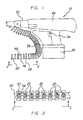
- system 10 includes a feedband 20 (which retains a series of fasteners 22) and a powered drill 24.
- Drill 24 includes a feedband delivery mechanism 26 for retaining and sequentially advancing feedband 20.
- Drill 24 is of a conventional design and can be an air gun that is powered either by a battery 28 or by an adjacent outlet via a power cord (not shown).
- drill 24 includes a chuck 32 for retaining and driving an individual fastener 22. Chuck 32 can be formed from three jaws that are selectively moved either inwardly or outwardly, via a key, to engage a head of fastener 22.
- Drill 24 further includes a trigger 34 for allowing a user to selectively deliver rotational power to chuck 32.
- the feed band delivery mechanism 26 is included along the forward end of drill 24.
- This delivery mechanism 26 includes a channel that retains feedband 20.
- Mechanism 26 additionally includes a motor (not shown) for incrementally advancing feedband 20 within the channel in a direction towards chuck 32.
- delivery mechanism 26 sequentially supplies the fasteners 22 to the drill chuck 32 so that they can be repeatedly and quickly driven by a user through the sheathing board 36 and into an underlying wood or steel framing member.
- a drill that meets of requirements of the present invention is sold by DuraSpin Products LLC of Cincinnati, Ohio under the trademark DuraSpinTM.
- FIG 2 is a detailed view of the feedband 20 of the present invention.
- Feedband 20 includes a series of interconnected membranes 38 that together form an elongated strip.
- the number of fasteners 22 will dictate the overall length of feedband 20.
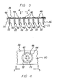
- Membranes 38 are each defined by a central extent 42 and a peripheral, crimped, circular edge 44 ( Fig. 4 ).
- each individual membrane 38 is pre-fit around the shaft 46 but beneath the head 48 of a fastener 22.
- the number of fasteners 22 retained within a feedband 20 corresponds to the number of membranes 38.
- Crimped edge 44 allows both the membrane 38 and its associated fastener 22 to be torn away from the surrounding feedband 20 as fastener 22 is driven into sheathing board 36. This tearing is achieved by crimped edge 44, which is frangible relative to the surrounding feedband 20 and ruptures upon application of axial or radial forces. Although this edge 44 is described as being crimped, those skilled in the art will appreciate that a perforated or a partially punctured periphery will also achieve these same objectives.
- both the feedband 20 and the individual membranes 38 are integrally formed from a polymeric compound.
- a preferred compound consists essentially of a thermal setting acrylic polymer, a butyl rubber and a softening agent.
- the acrylic polymer is included due to its good ultraviolet (UV) resistance and because it allows the compound to cure into a dimensionally stable compound.
- UV ultraviolet
- the use of other thermal setting plastic polymers, or combinations of such polymers, is within the scope of the present invention.
- the butyl rubber is included as a cheap and effective means of providing durability.
- the softening agent gives the compound a suitable degree of elasticity. Such softening agents keep the polymer pliable until such time as oxidation agents allow it to cure and harden.
- the preferred polymeric compound can chemically bond with a polymeric compound found under the protective face coating of some gypsum sheathing boards.
- the compound may also bond with a protective face coating of the board. Namely, after the polymer of the membrane 38 has become heated from the forces applied by drill 24, the membrane 38 is then seated within the sheathing board 36 as noted in Figure 6 . In this orientation the polymer of the membrane 38 is in direct contact with any polymers present within the interior of sheathing board 36. This contact allows the two polymers to form a chemical bond and thereby seal the penetration point. Once this bond is created, the softening agents within the polymers oxidize whereby the bonded polymers harden and lose their elastomeric properties. It has been found that the seal created by this chemical bond advantageously repels water and prevents the deterioration of gypsum board 36.
- polymeric compound for the membrane has been described as being preferred, those skilled in the art will realize that other polymeric compounds can be used to achieve the objectives of the present invention.
- a silicone can be used in place of the butyl rubber. While this may increase the price of the compound, no other adverse effects will be realized.
- One suitable composition is made by Bakor Company of Mississauga, Ontario under the trademark BlueskinTM. This composition is desirable due to its zero water vapor permeance and its ability to resist up to 9.1 lbs/sq inch of water. The manner in which the polymeric compound of the membrane acts in forming a seal will be described in greater detail hereinafter.
- each fastener 22 preferably includes a head 48 and a threaded body 46.
- feedband 20 can be adapted to retain non-threaded fasteners, such as nails.
- the body of each fastener 22 is secured through a central extent 42 of an associated membrane 38.
- each membrane 38 has a slotted central extent 42 which receives the body 46 of the threaded fastener 22.
- Fasteners 22 are thereafter positioned within the feedband such that the head 48 and the surface of feedband 20 are in direct contact with one another.
- the area defined by the peripheral crimped edge 44 of each membrane 38 is larger than the head 48 of the associated fastener 22.
- the area between the head 48 and the crimped edge 44 is defined as an outer membrane area 52.
- This excess material surrounds and seals the peripheral area of the fastener, which is the penetration point for the sheathing board, and yields increased surface water resistance.
- This mushroom effect is illustrated by the partial cross sectional view of Figure 7 .
- This mushroom effect is illustrated in more detail by the partial cross sectional view of Figure 8 .
- the delivery mechanism 26 of the drill 24 delivers an individual fastener 22 into the drill's chuck 32. Thereafter, engaging the trigger 34 causes the chuck 32 to rotate and thereby drives the fastener 22 into the sheathing member 36.
- the head 48 of the fastener 22 is securely seated and countersunk into the sheathing board 36 to avoid any out pouching at the fastener point. The result is a flat sheathing board surface that allows any number of exterior finishing systems to be applied.
- the present invention can be used in conjunction with a variety of sheathing members 36, it is particularly applicable to sheathing members with a protective face coating and an underlying polymeric compound.
- sheathing member is made by BPB North America Inc. under the trade name GlassRoc®.
- drilling an individual fastener 22 causes the crimped edge 44 of the associated membrane 38 to tear away from the feedband 26 and allows the membrane to seat within the sheathing member. Because the membrane 38 is elastic it becomes compressed under the pressure of the fastener 22. When an additional rotational force is applied to the fastener 22, the membrane 38 becomes heated.
- This heating of the membrane acts as a cure activator and facilitates a chemical bond between the membrane 38 and the underlying polymeric compound of the sheathing board 36 .
- This bond is beneficial insomuch as it prevents water intrusion at the point of penetration and cures to form a hardened compound which is resistant to UV rays.
Landscapes
- Engineering & Computer Science (AREA)
- Mechanical Engineering (AREA)
- General Engineering & Computer Science (AREA)
- Forms Removed On Construction Sites Or Auxiliary Members Thereof (AREA)
- Connection Of Plates (AREA)
- Slide Fasteners (AREA)
- Non-Metallic Protective Coatings For Printed Circuits (AREA)
- Building Environments (AREA)
- Barrages (AREA)
- Laminated Bodies (AREA)
Description
- The present invention relates to a fastening system for sheathing board. More particularly, the present invention relates to a fastening system that creates a seal between a fastener and an associated sheathing board to thereby prevent water intrusion and deterioration at the point of penetration.
- Sheathing board is a commonly employed building material and is used to create finished surfaces within homes and office buildings. These boards are nailed, screwed or otherwise secured by a fastener into the wood or steel framing members of a building. The walls created by sheathing boards are often load bearing, carrying the weight from other structural components or from external forces, such as wind, rain or snow. This can contribute to increased pulling loads applied to the fasteners. Because sheathing board is extensively used within buildings, there is a need for improving the speed at which these boards can be installed. At the same time, the speed and ease of installation must not compromise the integrity and safety of the resulting structure.
- Complicating matters further is the fact that sheathing board is often formed from gypsum and therefore subject to the detrimental effects of water. Although new gypsum compounds have been developed in an effort to lessen problems associated with water, the predominate make up of gypsum board is nevertheless gypsum and gypsum cannot be manufactured so as to be completely water resistant. Water intrusion into sheathing board is inherently problematic and can occur in the area around the fastener, which is called the penetration point. This water intrusion can cause a failure in the area around the fastener and a failure of the applied holding strength of the fasteners over the sheathing. This, in turn, can result in gypsum sheathing falling from its points of wall attachment and ultimately the complete failure of the board. These failures can be catastrophic.
- One limited solution to preventing water intrusion is the use of caulk around the penetration point. In fact, for a number of different finishing systems, there can be locally or nationally required building codes which require that fastener heads be sealed with water resistant caulk or tape. In some cases, building felts or raps are used to cover the entire exposed surface of the sheathing to act as a protective barrier. However, these prior systems tend to contract and/or expand and thereafter break down after long term exposure to ultra violet (UV) radiation and/or temperature variations. The instability of these prior systems in such environments means that they are not an ideal solution. Furthermore, all of these systems are labor intensive and greatly increase the time required for sheathing board installation. Due to the inhibiting cost disadvantage of these systems, if they are not required by local building codes, they are usually not employed. Thus, there exists a need in the art for water and weather resistant fasteners that can be quickly and easily installed.
- One known means of increasing the speed with which fasteners are driven is nailing strips. These strips are used to retain a series of fasteners, such as nails or screws. The strips enable a user to sequentially drive the fasteners, and in the process sever them from the strip, via an automated nailing machine or a powered drill. An example of a nailing strip is disclosed in
U.S. Patent 3,211,284 to Anstett . Anstett '284 discloses a nailing strip formed from a synthetic plastic material. A portion of the nailing strip is designed to break away once a nail is driven. This portion of the strip then acts as a weather tight seal for the head of the nail. - Similarly,
U.S. Patent 6,036,013 to Chen discloses a screw feed belt which holds a number of screws in an elongated strap. Connecting ribs are used to secure the individual screws. These ribs break upon the axial rotation of the screw and further permit the positioning of an associated positioning ring. The positioning ring includes a central opening that receives the shank of an associated screw. -
U.S. Patent 5,974,918 to Nakagawa et al. discloses a device for sequentially driving screws carried on a screw carrying strip. The device includes means for retaining and selectively advancing the screw carrying strip such that individual fasteners can be sequentially driven by the drill. - The use of water tight seals in conjunction with mechanical fasteners is also known in the art. For example,
U.S. Patent 2,439,516 to Holcomb discloses a washer with a disc like body that is adapted to be secured about the outer portion of a shank. The washer is formed from a rubber or a rubber-like substance and forms a seal about an associated opening to prevent the entrance of water. The washer is resilient and when under compression it completely fills the space between the head of the fastener and an underlying plate or sheet. - Although each of the above referenced inventions achieves its individual objective, they all suffer from a common drawbacks. Namely, none of the aforementioned inventions are specifically for use in installing sheathing board and none of the background inventions provide a system for quickly installing a series of fasteners in a completely water and/or weather resistant manner.
- It is therefore one of the objectives of this invention to provide a fastening system for securing a sheathing board to a framing member.
- It is also an object of this invention to provide a series of sealing membranes and associated fasteners that can be driven into a sheathing board by way of a feeding band and a powered drill.
- Still another object of this invention is to provide a fastening system wherein a chemical bond is created between a sealing membrane and the polymeric compound of an adjacent sheathing board, to thereby eliminate water intrusion and deterioration.
- These and other objectives are realized in a fastening system for use in securing gypsum sheathing board to an underlying framing member. The invention finds particular application with gypsum board that includes a protective face coating and an underlying polymeric compound.
- The system includes a feedband comprising a series of interconnected membranes, with each membrane defined by a central extent and a peripheral edge. Each membrane is preferably formed from a polymeric compound comprising a thermal setting plastic polymer and a softening agent.
- The polymeric compound preferably further comprises a butyl rubber. Alternatively, or in addition thereto, the polymeric compound preferably further comprises a silicon.
- During the seating of a fastener within the sheathing board, a chemical bond is formed between the membrane and the underlying polymeric compound of the adjacent gypsum board. This chemical bond is created after the membrane becomes heated as it is driven into the sheathing board.
- The system also includes a series of fasteners, with each fastener having a head and a threaded body. Each fastener is preferably a threaded fastener. The body of each fastener is secured through the central extent of an associated membrane such that the head and membrane are in contact. An outer membrane area is defined by the space between the head and the peripheral crimped edge. This outer membrane area is preferably forced upwardly around the head of the fastener when the fastener is driven into the gypsum board.
- The system further includes a powered drill that includes a feedband delivery mechanism, a chuck and a trigger. The trigger is used to selectively rotate the chuck. The delivery mechanism is used in retaining and selectively advancing the feedband such that the individual heads of the series of fasteners are sequentially delivered to the chuck and thereby enable the individual fasteners to be drilled into the gypsum board.
- Thus, when an individual fastener is drilled it causes the edge of the associated membrane to tear away from the feedband. The application of additional rotational force by the drill causes the membrane to become heated to thereby facilitate the chemical bond between the membrane and the underlying polymeric compound.
- The foregoing has outlined rather broadly the more pertinent and important features of the present invention in order that the detailed description of the invention that follows may be better understood so that the present contribution to the art can be more fully appreciated. Additional features of the invention will be described hereinafter which form the subject of the claims of the invention. It should be appreciated by those skilled in the art that the conception and the specific embodiment disclosed may be readily utilized as a basis for modifying or designing other structures for carrying out the same purposes of the present invention. It should also be realized by those skilled in the art that such equivalent constructions do not depart from the spirit and scope of the invention as set forth in the appended claims.
- For a fuller understanding of the nature and objects of the invention, reference should be had to the following detailed description taken in connection with the accompanying drawings in which:
-
Fig. 1 is a side elevational view of the fastening system of the present invention. -
Fig. 2 is a detailed view taken along line 2-2 ofFig. 1 . -
Fig. 3 is a side elevational view taken along line 3-3 ofFig. 2 . -
Fig. 4 is a detailed top plan view taken along line 4-4 ofFig. 3 . -
Fig. 5 is a side elevational view taken along line 5-5 ofFig. 4 . -
Fig. 6 is a partial cross sectional view showing two fasteners secured within a sheathing board. -
Fig. 7 is an additional partial cross sectional view showing two fasteners secured within a sheathing board. -
Fig. 8 is a partial cross sectional view taken along line 8-8 ofFig. 7 . - Similar reference characters refer to similar parts throughout the several views of the drawings.
- The present invention relates to a fastening system that is adapted for securing a sheathing board to an associated framing member. The system includes a feedband for retaining a series of fasteners and a powered drill for sequentially driving the fasteners. The feedband is made from a membrane of a polymeric compound. As the fastener is driven into the sheathing board, a portion of the membrane tears away from the surrounding feedband and becomes seated beneath the fastener. This acts to seal the penetration point and prevent water intrusion and otherwise prevents deterioration of the sheathing board. The various details of the present invention are described in greater detail hereinafter in conjunction with
Figures 1-6 . - Turning now to
Fig. 1 , thesystem 10 of the present invention is depicted. As illustrated,system 10 includes a feedband 20 (which retains a series of fasteners 22) and apowered drill 24.Drill 24, in turn, includes afeedband delivery mechanism 26 for retaining and sequentially advancingfeedband 20.Drill 24 is of a conventional design and can be an air gun that is powered either by abattery 28 or by an adjacent outlet via a power cord (not shown). As is also conventional,drill 24 includes achuck 32 for retaining and driving anindividual fastener 22.Chuck 32 can be formed from three jaws that are selectively moved either inwardly or outwardly, via a key, to engage a head offastener 22.Drill 24 further includes atrigger 34 for allowing a user to selectively deliver rotational power to chuck 32. - The feed
band delivery mechanism 26 is included along the forward end ofdrill 24. Thisdelivery mechanism 26 includes a channel that retainsfeedband 20.Mechanism 26 additionally includes a motor (not shown) for incrementally advancingfeedband 20 within the channel in a direction towardschuck 32. Thus,delivery mechanism 26 sequentially supplies thefasteners 22 to thedrill chuck 32 so that they can be repeatedly and quickly driven by a user through thesheathing board 36 and into an underlying wood or steel framing member. A drill that meets of requirements of the present invention is sold by DuraSpin Products LLC of Cincinnati, Ohio under the trademark DuraSpin™. -
Figure 2 is a detailed view of thefeedband 20 of the present invention.Feedband 20 includes a series ofinterconnected membranes 38 that together form an elongated strip. The number offasteners 22 will dictate the overall length offeedband 20.Membranes 38 are each defined by acentral extent 42 and a peripheral, crimped, circular edge 44 (Fig. 4 ). As noted inFigure 3 , eachindividual membrane 38 is pre-fit around theshaft 46 but beneath thehead 48 of afastener 22. Thus, the number offasteners 22 retained within afeedband 20 corresponds to the number ofmembranes 38. - Crimped
edge 44 allows both themembrane 38 and its associatedfastener 22 to be torn away from the surroundingfeedband 20 asfastener 22 is driven intosheathing board 36. This tearing is achieved by crimpededge 44, which is frangible relative to the surroundingfeedband 20 and ruptures upon application of axial or radial forces. Although thisedge 44 is described as being crimped, those skilled in the art will appreciate that a perforated or a partially punctured periphery will also achieve these same objectives. - In the preferred embodiment, both the
feedband 20 and theindividual membranes 38 are integrally formed from a polymeric compound. A preferred compound consists essentially of a thermal setting acrylic polymer, a butyl rubber and a softening agent. The acrylic polymer is included due to its good ultraviolet (UV) resistance and because it allows the compound to cure into a dimensionally stable compound. The use of other thermal setting plastic polymers, or combinations of such polymers, is within the scope of the present invention. The butyl rubber is included as a cheap and effective means of providing durability. Finally, the softening agent gives the compound a suitable degree of elasticity. Such softening agents keep the polymer pliable until such time as oxidation agents allow it to cure and harden. - It has been found that the preferred polymeric compound can chemically bond with a polymeric compound found under the protective face coating of some gypsum sheathing boards. The compound may also bond with a protective face coating of the board. Namely, after the polymer of the
membrane 38 has become heated from the forces applied bydrill 24, themembrane 38 is then seated within thesheathing board 36 as noted inFigure 6 . In this orientation the polymer of themembrane 38 is in direct contact with any polymers present within the interior of sheathingboard 36. This contact allows the two polymers to form a chemical bond and thereby seal the penetration point. Once this bond is created, the softening agents within the polymers oxidize whereby the bonded polymers harden and lose their elastomeric properties. It has been found that the seal created by this chemical bond advantageously repels water and prevents the deterioration ofgypsum board 36. - Although the above described polymeric compound for the membrane has been described as being preferred, those skilled in the art will realize that other polymeric compounds can be used to achieve the objectives of the present invention. For instance, a silicone can be used in place of the butyl rubber. While this may increase the price of the compound, no other adverse effects will be realized. Likewise, it is also within the scope of the present invention to form the feedband from a commercially available polymeric material. One suitable composition is made by Bakor Company of Mississauga, Ontario under the trademark Blueskin™. This composition is desirable due to its zero water vapor permeance and its ability to resist up to 9.1 lbs/sq inch of water. The manner in which the polymeric compound of the membrane acts in forming a seal will be described in greater detail hereinafter.
- With reference now to
Figures 2 and3 , the manner in which the feedband is employed in retaining a series of fasteners is depicted. Specifically, eachfastener 22 preferably includes ahead 48 and a threadedbody 46. However, feedband 20 can be adapted to retain non-threaded fasteners, such as nails. The body of eachfastener 22 is secured through acentral extent 42 of an associatedmembrane 38. To achieve this, eachmembrane 38 has a slottedcentral extent 42 which receives thebody 46 of the threadedfastener 22.Fasteners 22 are thereafter positioned within the feedband such that thehead 48 and the surface offeedband 20 are in direct contact with one another. - With specific reference to
Figure 4 , it will be noted that the area defined by the peripheral crimpededge 44 of eachmembrane 38 is larger than thehead 48 of the associatedfastener 22. Specifically, the area between thehead 48 and the crimpededge 44 is defined as anouter membrane area 52. As noted above, driving afastener 22 with thedrill 24 will cause themembrane 38 to detach from the surroundingfeedband 20. Thereafter, driving thefastener 22 further into thesheathing board 36 will cause theouter membrane area 52 to mushroom up about the majority of the periphery of the countersunkfastener head 22. In other words, the excess material of theouter membrane area 52 will be directed upwardly as thehead 48 of thefastener 22 is driven into thesheathing board 36. This excess material surrounds and seals the peripheral area of the fastener, which is the penetration point for the sheathing board, and yields increased surface water resistance. This mushroom effect is illustrated by the partial cross sectional view ofFigure 7 . This mushroom effect is illustrated in more detail by the partial cross sectional view ofFigure 8 . - Thus, in use, the
delivery mechanism 26 of thedrill 24 delivers anindividual fastener 22 into the drill'schuck 32. Thereafter, engaging thetrigger 34 causes thechuck 32 to rotate and thereby drives thefastener 22 into thesheathing member 36. Ideally, thehead 48 of thefastener 22 is securely seated and countersunk into thesheathing board 36 to avoid any out pouching at the fastener point. The result is a flat sheathing board surface that allows any number of exterior finishing systems to be applied. - Although the present invention can be used in conjunction with a variety of
sheathing members 36, it is particularly applicable to sheathing members with a protective face coating and an underlying polymeric compound. One example of such a sheathing member is made by BPB North America Inc. under the trade name GlassRoc®. In accordance with the present invention, drilling anindividual fastener 22 causes the crimpededge 44 of the associatedmembrane 38 to tear away from thefeedband 26 and allows the membrane to seat within the sheathing member. Because themembrane 38 is elastic it becomes compressed under the pressure of thefastener 22. When an additional rotational force is applied to thefastener 22, themembrane 38 becomes heated. This heating of the membrane acts as a cure activator and facilitates a chemical bond between themembrane 38 and the underlying polymeric compound of thesheathing board 36. This bond is beneficial insomuch as it prevents water intrusion at the point of penetration and cures to form a hardened compound which is resistant to UV rays. - The present disclosure includes that contained in the appended claims, as well as that of the foregoing description. Although this invention has been described in its preferred form with a certain degree of particularity, it is understood that the present disclosure of the preferred form has been made only by way of example and that numerous changes in the details of construction and the combination and arrangement of parts may be resorted to without departing from the spirit and scope of the invention.
- Now that the invention has been described,
Claims (8)
- A fastening system (10) for use with a sheathing board (36) consisting of a polymeric material, the system (10) comprising:a feedband (20) made up of a series of interconnected membranes (38), each membrane (38) defined by a central extent (42) and a peripheral edge (44),a series of fasteners (22), each fastener (22) having a head (48) and a body (46), the body (46) of each fastener (22) being secured through the central extent (42) of an associated membrane (38) such that the head (48) and membrane (38) are in contact and such that driving the fastener (22) causes the edge (44) of the associated membrane (38) to tear away from the feedband (20);a drill (24) including a delivery mechanism (26), the delivery mechanism (26) retaining and selectively advancing the feedband (20) such that the individual fasteners (22) can be sequentially driven by the drill (24);characterised in that each membrane (38) is formed at least in part from a polymeric compound, and driving an individual fastener (22) causes the fastener (22) to seat within the sheathing board (36) so that a chemical bond is formed between the polymeric compound of the membrane (38) and the polymeric material of the sheathing board (36).
- The system as claimed in claim 1, wherein an outer membrane area (52) is defined by the space between the head (48) of a fastener (22) and the peripheral edge (44) of an associated membrane (38), the outer membrane area (52) being forced upwardly around the head (48) of the fastener (22) when the fastener (22) is driven into the sheathing board (36).
- The system as claimed in claim 1 or claim 2, wherein the fastener (22) is a threaded fastener.
- The system as claimed in any preceding claim, wherein the polymeric material of the membrane (38) comprises a thermal setting plastic polymer and a softening agent.
- The system as claimed in claim 4, wherein the polymeric material of the membrane (38) further comprises a butyl rubber.
- The system as claimed in claim 4, wherein the polymeric material of the membrane (38) further comprises a silicone.
- The system as claimed in any preceding claim, wherein the chemical bond is formed only after the membrane (38) becomes heated.
- The system as claimed in claim 7, wherein the heating of the membrane (38) is effected by a rotational force provided by the drill (34).
Priority Applications (2)
| Application Number | Priority Date | Filing Date | Title |
|---|---|---|---|
| PL07796167T PL2029324T3 (en) | 2006-06-15 | 2007-06-15 | Fastening system for sheathing board |
| CY20131101032T CY1114672T1 (en) | 2006-06-15 | 2013-11-21 | INSTALLATION SYSTEM FOR INVESTMENT PLATE |
Applications Claiming Priority (2)
| Application Number | Priority Date | Filing Date | Title |
|---|---|---|---|
| US11/454,149 US7594456B2 (en) | 2006-06-15 | 2006-06-15 | Fastening system for sheathing board |
| PCT/US2007/014070 WO2007146423A2 (en) | 2006-06-15 | 2007-06-15 | Fastening system for sheathing board |
Publications (3)
| Publication Number | Publication Date |
|---|---|
| EP2029324A2 EP2029324A2 (en) | 2009-03-04 |
| EP2029324A4 EP2029324A4 (en) | 2011-09-28 |
| EP2029324B1 true EP2029324B1 (en) | 2013-08-21 |
Family
ID=38832566
Family Applications (1)
| Application Number | Title | Priority Date | Filing Date |
|---|---|---|---|
| EP07796167.0A Active EP2029324B1 (en) | 2006-06-15 | 2007-06-15 | Fastening system for sheathing board |
Country Status (11)
| Country | Link |
|---|---|
| US (4) | US7594456B2 (en) |
| EP (1) | EP2029324B1 (en) |
| CA (1) | CA2679053C (en) |
| CY (1) | CY1114672T1 (en) |
| DK (1) | DK2029324T3 (en) |
| ES (1) | ES2436282T3 (en) |
| NO (1) | NO336543B1 (en) |
| PL (1) | PL2029324T3 (en) |
| PT (1) | PT2029324E (en) |
| RS (1) | RS53043B (en) |
| WO (1) | WO2007146423A2 (en) |
Families Citing this family (8)
| Publication number | Priority date | Publication date | Assignee | Title |
|---|---|---|---|---|
| US7594456B2 (en) * | 2006-06-15 | 2009-09-29 | Certain Teed Gypsum, Inc. | Fastening system for sheathing board |
| DE102009041400A1 (en) * | 2009-09-12 | 2011-03-24 | Fischerwerke Gmbh & Co. Kg | nail strips |
| US10421176B2 (en) | 2016-02-19 | 2019-09-24 | National Nail Corp. | Strip of collated fasteners and related methods of use |
| US10857770B2 (en) | 2016-04-01 | 2020-12-08 | Certainteed Gypsum, Inc. | Building board and method of forming the building board |
| CA3012917A1 (en) * | 2017-08-15 | 2019-02-15 | Ruwka Inc. | Panel installation apparatus |
| CA3086492C (en) | 2017-12-19 | 2023-11-14 | Saint-Gobain Adfors Canada, Ltd. | A reinforcing layer, a cementitious board, and method of forming the cementitious board |
| US10816025B1 (en) * | 2019-08-23 | 2020-10-27 | Guangzhe Enterprise Co., Ltd. | Screw band |
| US20240227142A9 (en) * | 2022-10-20 | 2024-07-11 | Terry Nelson | Extension tool to hang attachments in exterior spaces |
Family Cites Families (27)
| Publication number | Priority date | Publication date | Assignee | Title |
|---|---|---|---|---|
| US1979470A (en) * | 1930-05-10 | 1934-11-06 | Gladding Mcbean & Company | Method of joining bell and spigot pipe sections |
| US2203294A (en) * | 1939-03-16 | 1940-06-04 | Ralph L Engle | Nail for fastening sheeting |
| US2439516A (en) | 1946-10-07 | 1948-04-13 | Sally O B Holcomb | Nail sealing washer |
| US2981651A (en) * | 1956-08-02 | 1961-04-25 | American Marietta Co | Sealing members and methods |
| US3211284A (en) | 1962-07-23 | 1965-10-12 | Edgar P Anstett | Nailing strip |
| US3299766A (en) * | 1964-04-30 | 1967-01-24 | Gould William | Sealing element for fastener devices |
| DE2042768C3 (en) | 1970-08-28 | 1981-01-29 | Hilti Ag, Schaan (Liechtenstein) | Magazine equipped with nails for a powder-powered setting tool |
| DE7344665U (en) | 1973-12-17 | 1974-03-14 | Hilti Ag | Magazine for powder-powered setting tools |
| US3994200A (en) | 1973-01-15 | 1976-11-30 | Swanson Roger I | Fastener-washer combination |
| SE7405197L (en) | 1974-04-18 | 1975-10-20 | Bulten Kanthal Ab | SCREW BAND |
| US4667545A (en) * | 1985-06-03 | 1987-05-26 | Gould Jr Frederick H | Screw gun automatic feed |
| AT382697B (en) * | 1985-07-11 | 1987-03-25 | Sfs Stadler Ag | Strip magazine |
| US4862664A (en) * | 1987-12-23 | 1989-09-05 | Romine Robert L | Roofing fastener for fastener assembly and roof assemblies |
| US5542323A (en) * | 1994-04-28 | 1996-08-06 | G. Lyle Habermehl | Screw strip with overlapping washers, and method and apparatus for installation |
| US5443345A (en) | 1994-06-20 | 1995-08-22 | Illinois Tool Works Inc. | Fastener-sleeve assembly and strip of collated fasteners |
| JPH09285972A (en) * | 1996-04-18 | 1997-11-04 | Hitachi Koki Co Ltd | Screw tightening tool |
| US5921736A (en) | 1997-06-09 | 1999-07-13 | Habermehl; Gordon Lyle | Collated drywall screws |
| US6010291A (en) * | 1999-01-29 | 2000-01-04 | Schwingle; Shawn L. | Collatable cap nail |
| US6036013A (en) | 1999-02-16 | 2000-03-14 | Chen; Sen-Yang | Screw feed belt |
| US7105587B2 (en) * | 2001-03-07 | 2006-09-12 | Innovative Construction And Building Materials | Method and composition for polymer-reinforced composite cementitious construction material |
| US20050159057A1 (en) * | 2001-06-06 | 2005-07-21 | Bpb Plc | Exterior sheathing weather barrier construction and method of manufacture |
| US20030102236A1 (en) | 2001-12-04 | 2003-06-05 | Wei Lin Chao | Screw band with washers |
| US6811366B2 (en) | 2003-03-14 | 2004-11-02 | Ho-Tien Chen | Screw band with washers |
| US7032482B1 (en) * | 2003-10-31 | 2006-04-25 | Senco Products, Inc. | Tensioning device apparatus for a bottom feed screw driving tool for use with collated screws |
| US7351022B2 (en) * | 2004-09-30 | 2008-04-01 | Denslow Clark A | Unified multi-part head for a staked fastener |
| US7594456B2 (en) * | 2006-06-15 | 2009-09-29 | Certain Teed Gypsum, Inc. | Fastening system for sheathing board |
| JP2010059980A (en) * | 2008-09-01 | 2010-03-18 | Pias Hanbai Kk | Screw coupling strip used in continuous screw tightening machine |
-
2006
- 2006-06-15 US US11/454,149 patent/US7594456B2/en not_active Expired - Fee Related
-
2007
- 2007-06-15 ES ES07796167T patent/ES2436282T3/en active Active
- 2007-06-15 DK DK07796167.0T patent/DK2029324T3/en active
- 2007-06-15 PT PT77961670T patent/PT2029324E/en unknown
- 2007-06-15 RS RS20130519A patent/RS53043B/en unknown
- 2007-06-15 PL PL07796167T patent/PL2029324T3/en unknown
- 2007-06-15 EP EP07796167.0A patent/EP2029324B1/en active Active
- 2007-06-15 CA CA2679053A patent/CA2679053C/en not_active Expired - Fee Related
- 2007-06-15 WO PCT/US2007/014070 patent/WO2007146423A2/en not_active Ceased
-
2008
- 2008-12-23 NO NO20085350A patent/NO336543B1/en not_active IP Right Cessation
-
2009
- 2009-09-28 US US12/567,857 patent/US8353401B2/en not_active Expired - Fee Related
-
2013
- 2013-01-15 US US13/741,622 patent/US8832923B2/en not_active Expired - Fee Related
- 2013-11-21 CY CY20131101032T patent/CY1114672T1/en unknown
-
2014
- 2014-09-12 US US14/485,459 patent/US9068586B2/en not_active Expired - Fee Related
Also Published As
| Publication number | Publication date |
|---|---|
| US8832923B2 (en) | 2014-09-16 |
| US20100132519A1 (en) | 2010-06-03 |
| WO2007146423A3 (en) | 2008-07-17 |
| RS53043B (en) | 2014-04-30 |
| US20070289885A1 (en) | 2007-12-20 |
| US20140373336A1 (en) | 2014-12-25 |
| EP2029324A4 (en) | 2011-09-28 |
| CA2679053C (en) | 2013-01-08 |
| PL2029324T3 (en) | 2014-03-31 |
| DK2029324T3 (en) | 2013-12-02 |
| CY1114672T1 (en) | 2016-10-05 |
| WO2007146423A2 (en) | 2007-12-21 |
| CA2679053A1 (en) | 2007-12-21 |
| US9068586B2 (en) | 2015-06-30 |
| PT2029324E (en) | 2013-11-27 |
| US8353401B2 (en) | 2013-01-15 |
| EP2029324A2 (en) | 2009-03-04 |
| ES2436282T3 (en) | 2013-12-30 |
| US7594456B2 (en) | 2009-09-29 |
| NO20085350L (en) | 2009-01-12 |
| NO336543B1 (en) | 2015-09-21 |
| US20130193015A1 (en) | 2013-08-01 |
Similar Documents
| Publication | Publication Date | Title |
|---|---|---|
| US9068586B2 (en) | Method for forming a seal between a fastener and associated sheathing board | |
| CA2514829C (en) | Construction unit mounting system | |
| US5987837A (en) | Reamer screw and building panels erected with reamer screws | |
| US6233889B1 (en) | Ventilated roof membrane plate and method of installing membrane roof utilizing same | |
| US5772816A (en) | Reinforced tape strip for perimeter securement of a membrane roof and method for attaching | |
| AU7880998A (en) | Stress plate with depending sleeve | |
| US20120073201A1 (en) | Storm panel bracket | |
| US12146517B2 (en) | Self-sealing fastener | |
| US4949523A (en) | Non-penetrating elastomeric membrane anchoring system | |
| US20080010918A1 (en) | Nail fin for window frame assembly | |
| US9745789B2 (en) | Prefabricated flashing product | |
| US9334651B2 (en) | System and method for attaching shingles to a roof | |
| US4571902A (en) | Panel mounting system and method for mounting panels | |
| JP2002303314A (en) | Resin washer | |
| JP3084325B2 (en) | Vertical joint structure | |
| GB2317429A (en) | Fastener for corrugated sheeting | |
| WO2008130152A1 (en) | Member and method for remodeling concrete water tank | |
| US4858412A (en) | Non-penetrating elastomeric membrane anchoring system | |
| CA2221679C (en) | Reamer screw and building panels erected with reamer screws | |
| AU685138B2 (en) | Fastening bracket | |
| JP2726430B2 (en) | Mechanical roof fastening device | |
| JP2006045824A (en) | Building panel mounting structure | |
| JPH047446A (en) | Outer surface waterproof construction material of building and method for construction of outer surface of building using the same | |
| NZ720944B (en) | A washer for use with a winged fastener |
Legal Events
| Date | Code | Title | Description |
|---|---|---|---|
| PUAI | Public reference made under article 153(3) epc to a published international application that has entered the european phase |
Free format text: ORIGINAL CODE: 0009012 |
|
| 17P | Request for examination filed |
Effective date: 20081229 |
|
| AK | Designated contracting states |
Kind code of ref document: A2 Designated state(s): AT BE BG CH CY CZ DE DK EE ES FI FR GB GR HU IE IS IT LI LT LU LV MC MT NL PL PT RO SE SI SK TR |
|
| AX | Request for extension of the european patent |
Extension state: AL BA HR MK RS |
|
| RAX | Requested extension states of the european patent have changed |
Extension state: RS Payment date: 20090223 Extension state: MK Payment date: 20090223 Extension state: HR Payment date: 20090223 Extension state: BA Payment date: 20090223 Extension state: AL Payment date: 20090223 |
|
| A4 | Supplementary search report drawn up and despatched |
Effective date: 20110829 |
|
| RIC1 | Information provided on ipc code assigned before grant |
Ipc: F16J 15/14 20060101ALI20110823BHEP Ipc: F16B 27/00 20060101ALI20110823BHEP Ipc: B25B 23/04 20060101AFI20110823BHEP Ipc: B65D 85/24 20060101ALI20110823BHEP Ipc: B65D 73/02 20060101ALI20110823BHEP |
|
| RIC1 | Information provided on ipc code assigned before grant |
Ipc: F16B 27/00 20060101ALI20120416BHEP Ipc: F16J 15/14 20060101ALI20120416BHEP Ipc: B25B 23/04 20060101AFI20120416BHEP Ipc: B65D 85/24 20060101ALI20120416BHEP Ipc: B65D 73/02 20060101ALI20120416BHEP |
|
| GRAP | Despatch of communication of intention to grant a patent |
Free format text: ORIGINAL CODE: EPIDOSNIGR1 |
|
| 17Q | First examination report despatched |
Effective date: 20121016 |
|
| GRAP | Despatch of communication of intention to grant a patent |
Free format text: ORIGINAL CODE: EPIDOSNIGR1 |
|
| INTG | Intention to grant announced |
Effective date: 20130326 |
|
| GRAS | Grant fee paid |
Free format text: ORIGINAL CODE: EPIDOSNIGR3 |
|
| GRAA | (expected) grant |
Free format text: ORIGINAL CODE: 0009210 |
|
| AK | Designated contracting states |
Kind code of ref document: B1 Designated state(s): AT BE BG CH CY CZ DE DK EE ES FI FR GB GR HU IE IS IT LI LT LU LV MC MT NL PL PT RO SE SI SK TR |
|
| AX | Request for extension of the european patent |
Extension state: AL BA HR MK RS |
|
| REG | Reference to a national code |
Ref country code: GB Ref legal event code: FG4D |
|
| REG | Reference to a national code |
Ref country code: CH Ref legal event code: EP |
|
| REG | Reference to a national code |
Ref country code: AT Ref legal event code: REF Ref document number: 627775 Country of ref document: AT Kind code of ref document: T Effective date: 20130915 |
|
| REG | Reference to a national code |
Ref country code: IE Ref legal event code: FG4D |
|
| REG | Reference to a national code |
Ref country code: DE Ref legal event code: R096 Ref document number: 602007032424 Country of ref document: DE Effective date: 20131017 |
|
| REG | Reference to a national code |
Ref country code: PT Ref legal event code: SC4A Free format text: AVAILABILITY OF NATIONAL TRANSLATION Effective date: 20131120 |
|
| REG | Reference to a national code |
Ref country code: DK Ref legal event code: T3 Effective date: 20131125 |
|
| REG | Reference to a national code |
Ref country code: SE Ref legal event code: TRGR |
|
| REG | Reference to a national code |
Ref country code: ES Ref legal event code: FG2A Ref document number: 2436282 Country of ref document: ES Kind code of ref document: T3 Effective date: 20131230 |
|
| REG | Reference to a national code |
Ref country code: RO Ref legal event code: EPE |
|
| REG | Reference to a national code |
Ref country code: NL Ref legal event code: VDEP Effective date: 20130821 Ref country code: AT Ref legal event code: MK05 Ref document number: 627775 Country of ref document: AT Kind code of ref document: T Effective date: 20130821 |
|
| REG | Reference to a national code |
Ref country code: LT Ref legal event code: MG4D |
|
| PG25 | Lapsed in a contracting state [announced via postgrant information from national office to epo] |
Ref country code: AT Free format text: LAPSE BECAUSE OF FAILURE TO SUBMIT A TRANSLATION OF THE DESCRIPTION OR TO PAY THE FEE WITHIN THE PRESCRIBED TIME-LIMIT Effective date: 20130821 Ref country code: IS Free format text: LAPSE BECAUSE OF FAILURE TO SUBMIT A TRANSLATION OF THE DESCRIPTION OR TO PAY THE FEE WITHIN THE PRESCRIBED TIME-LIMIT Effective date: 20131221 Ref country code: LT Free format text: LAPSE BECAUSE OF FAILURE TO SUBMIT A TRANSLATION OF THE DESCRIPTION OR TO PAY THE FEE WITHIN THE PRESCRIBED TIME-LIMIT Effective date: 20130821 |
|
| REG | Reference to a national code |
Ref country code: EE Ref legal event code: FG4A Ref document number: E008687 Country of ref document: EE Effective date: 20131121 |
|
| REG | Reference to a national code |
Ref country code: GR Ref legal event code: EP Ref document number: 20130402479 Country of ref document: GR Effective date: 20140102 |
|
| PG25 | Lapsed in a contracting state [announced via postgrant information from national office to epo] |
Ref country code: SI Free format text: LAPSE BECAUSE OF FAILURE TO SUBMIT A TRANSLATION OF THE DESCRIPTION OR TO PAY THE FEE WITHIN THE PRESCRIBED TIME-LIMIT Effective date: 20130821 Ref country code: BE Free format text: LAPSE BECAUSE OF FAILURE TO SUBMIT A TRANSLATION OF THE DESCRIPTION OR TO PAY THE FEE WITHIN THE PRESCRIBED TIME-LIMIT Effective date: 20130821 Ref country code: LV Free format text: LAPSE BECAUSE OF FAILURE TO SUBMIT A TRANSLATION OF THE DESCRIPTION OR TO PAY THE FEE WITHIN THE PRESCRIBED TIME-LIMIT Effective date: 20130821 |
|
| PG25 | Lapsed in a contracting state [announced via postgrant information from national office to epo] |
Ref country code: NL Free format text: LAPSE BECAUSE OF FAILURE TO SUBMIT A TRANSLATION OF THE DESCRIPTION OR TO PAY THE FEE WITHIN THE PRESCRIBED TIME-LIMIT Effective date: 20130821 Ref country code: CZ Free format text: LAPSE BECAUSE OF FAILURE TO SUBMIT A TRANSLATION OF THE DESCRIPTION OR TO PAY THE FEE WITHIN THE PRESCRIBED TIME-LIMIT Effective date: 20130821 Ref country code: SK Free format text: LAPSE BECAUSE OF FAILURE TO SUBMIT A TRANSLATION OF THE DESCRIPTION OR TO PAY THE FEE WITHIN THE PRESCRIBED TIME-LIMIT Effective date: 20130821 |
|
| PLBE | No opposition filed within time limit |
Free format text: ORIGINAL CODE: 0009261 |
|
| STAA | Information on the status of an ep patent application or granted ep patent |
Free format text: STATUS: NO OPPOSITION FILED WITHIN TIME LIMIT |
|
| 26N | No opposition filed |
Effective date: 20140522 |
|
| REG | Reference to a national code |
Ref country code: DE Ref legal event code: R097 Ref document number: 602007032424 Country of ref document: DE Effective date: 20140522 |
|
| REG | Reference to a national code |
Ref country code: DE Ref legal event code: R119 Ref document number: 602007032424 Country of ref document: DE |
|
| PG25 | Lapsed in a contracting state [announced via postgrant information from national office to epo] |
Ref country code: LU Free format text: LAPSE BECAUSE OF FAILURE TO SUBMIT A TRANSLATION OF THE DESCRIPTION OR TO PAY THE FEE WITHIN THE PRESCRIBED TIME-LIMIT Effective date: 20140615 Ref country code: MC Free format text: LAPSE BECAUSE OF FAILURE TO SUBMIT A TRANSLATION OF THE DESCRIPTION OR TO PAY THE FEE WITHIN THE PRESCRIBED TIME-LIMIT Effective date: 20130821 |
|
| REG | Reference to a national code |
Ref country code: CH Ref legal event code: PL |
|
| REG | Reference to a national code |
Ref country code: FR Ref legal event code: ST Effective date: 20150227 |
|
| REG | Reference to a national code |
Ref country code: DE Ref legal event code: R119 Ref document number: 602007032424 Country of ref document: DE Effective date: 20150101 |
|
| PG25 | Lapsed in a contracting state [announced via postgrant information from national office to epo] |
Ref country code: DE Free format text: LAPSE BECAUSE OF NON-PAYMENT OF DUE FEES Effective date: 20150101 Ref country code: LI Free format text: LAPSE BECAUSE OF NON-PAYMENT OF DUE FEES Effective date: 20140630 Ref country code: CH Free format text: LAPSE BECAUSE OF NON-PAYMENT OF DUE FEES Effective date: 20140630 |
|
| PG25 | Lapsed in a contracting state [announced via postgrant information from national office to epo] |
Ref country code: FR Free format text: LAPSE BECAUSE OF NON-PAYMENT OF DUE FEES Effective date: 20140630 |
|
| PGFP | Annual fee paid to national office [announced via postgrant information from national office to epo] |
Ref country code: RO Payment date: 20150507 Year of fee payment: 9 Ref country code: BG Payment date: 20150512 Year of fee payment: 9 Ref country code: GB Payment date: 20150610 Year of fee payment: 9 Ref country code: CY Payment date: 20150518 Year of fee payment: 9 Ref country code: ES Payment date: 20150512 Year of fee payment: 9 Ref country code: PT Payment date: 20150615 Year of fee payment: 9 Ref country code: EE Payment date: 20150526 Year of fee payment: 9 |
|
| PGFP | Annual fee paid to national office [announced via postgrant information from national office to epo] |
Ref country code: IE Payment date: 20150609 Year of fee payment: 9 Ref country code: PL Payment date: 20150504 Year of fee payment: 9 Ref country code: GR Payment date: 20150518 Year of fee payment: 9 |
|
| PGFP | Annual fee paid to national office [announced via postgrant information from national office to epo] |
Ref country code: IT Payment date: 20150625 Year of fee payment: 9 |
|
| PG25 | Lapsed in a contracting state [announced via postgrant information from national office to epo] |
Ref country code: MT Free format text: LAPSE BECAUSE OF FAILURE TO SUBMIT A TRANSLATION OF THE DESCRIPTION OR TO PAY THE FEE WITHIN THE PRESCRIBED TIME-LIMIT Effective date: 20130821 |
|
| PG25 | Lapsed in a contracting state [announced via postgrant information from national office to epo] |
Ref country code: HU Free format text: LAPSE BECAUSE OF FAILURE TO SUBMIT A TRANSLATION OF THE DESCRIPTION OR TO PAY THE FEE WITHIN THE PRESCRIBED TIME-LIMIT; INVALID AB INITIO Effective date: 20070615 |
|
| REG | Reference to a national code |
Ref country code: EE Ref legal event code: MM4A Ref document number: E008687 Country of ref document: EE Effective date: 20160630 |
|
| PG25 | Lapsed in a contracting state [announced via postgrant information from national office to epo] |
Ref country code: CY Free format text: LAPSE BECAUSE OF NON-PAYMENT OF DUE FEES Effective date: 20160615 Ref country code: RO Free format text: LAPSE BECAUSE OF NON-PAYMENT OF DUE FEES Effective date: 20160615 |
|
| PG25 | Lapsed in a contracting state [announced via postgrant information from national office to epo] |
Ref country code: PT Free format text: LAPSE BECAUSE OF NON-PAYMENT OF DUE FEES Effective date: 20161215 |
|
| GBPC | Gb: european patent ceased through non-payment of renewal fee |
Effective date: 20160615 |
|
| REG | Reference to a national code |
Ref country code: GR Ref legal event code: ML Ref document number: 20130402479 Country of ref document: GR Effective date: 20170109 |
|
| REG | Reference to a national code |
Ref country code: IE Ref legal event code: MM4A |
|
| PG25 | Lapsed in a contracting state [announced via postgrant information from national office to epo] |
Ref country code: GR Free format text: LAPSE BECAUSE OF NON-PAYMENT OF DUE FEES Effective date: 20170109 Ref country code: EE Free format text: LAPSE BECAUSE OF NON-PAYMENT OF DUE FEES Effective date: 20160630 |
|
| PG25 | Lapsed in a contracting state [announced via postgrant information from national office to epo] |
Ref country code: IE Free format text: LAPSE BECAUSE OF NON-PAYMENT OF DUE FEES Effective date: 20160615 Ref country code: BG Free format text: LAPSE BECAUSE OF NON-PAYMENT OF DUE FEES Effective date: 20170131 Ref country code: GB Free format text: LAPSE BECAUSE OF NON-PAYMENT OF DUE FEES Effective date: 20160615 |
|
| PG25 | Lapsed in a contracting state [announced via postgrant information from national office to epo] |
Ref country code: IT Free format text: LAPSE BECAUSE OF NON-PAYMENT OF DUE FEES Effective date: 20160615 |
|
| PG25 | Lapsed in a contracting state [announced via postgrant information from national office to epo] |
Ref country code: PL Free format text: LAPSE BECAUSE OF NON-PAYMENT OF DUE FEES Effective date: 20160615 |
|
| PG25 | Lapsed in a contracting state [announced via postgrant information from national office to epo] |
Ref country code: ES Free format text: LAPSE BECAUSE OF NON-PAYMENT OF DUE FEES Effective date: 20160616 |
|
| REG | Reference to a national code |
Ref country code: ES Ref legal event code: FD2A Effective date: 20181203 |
|
| PGFP | Annual fee paid to national office [announced via postgrant information from national office to epo] |
Ref country code: FI Payment date: 20200609 Year of fee payment: 14 Ref country code: TR Payment date: 20200615 Year of fee payment: 14 Ref country code: DK Payment date: 20200610 Year of fee payment: 14 |
|
| PGFP | Annual fee paid to national office [announced via postgrant information from national office to epo] |
Ref country code: SE Payment date: 20200610 Year of fee payment: 14 |
|
| REG | Reference to a national code |
Ref country code: FI Ref legal event code: MAE |
|
| REG | Reference to a national code |
Ref country code: DK Ref legal event code: EBP Effective date: 20210630 |
|
| REG | Reference to a national code |
Ref country code: SE Ref legal event code: EUG |
|
| PG25 | Lapsed in a contracting state [announced via postgrant information from national office to epo] |
Ref country code: FI Free format text: LAPSE BECAUSE OF NON-PAYMENT OF DUE FEES Effective date: 20210615 |
|
| PG25 | Lapsed in a contracting state [announced via postgrant information from national office to epo] |
Ref country code: SE Free format text: LAPSE BECAUSE OF NON-PAYMENT OF DUE FEES Effective date: 20210616 |
|
| PG25 | Lapsed in a contracting state [announced via postgrant information from national office to epo] |
Ref country code: DK Free format text: LAPSE BECAUSE OF NON-PAYMENT OF DUE FEES Effective date: 20210630 |
|
| PG25 | Lapsed in a contracting state [announced via postgrant information from national office to epo] |
Ref country code: TR Free format text: LAPSE BECAUSE OF NON-PAYMENT OF DUE FEES Effective date: 20210615 |