EP2029030B1 - Surgical apparatus - Google Patents
Surgical apparatus Download PDFInfo
- Publication number
- EP2029030B1 EP2029030B1 EP07732604A EP07732604A EP2029030B1 EP 2029030 B1 EP2029030 B1 EP 2029030B1 EP 07732604 A EP07732604 A EP 07732604A EP 07732604 A EP07732604 A EP 07732604A EP 2029030 B1 EP2029030 B1 EP 2029030B1
- Authority
- EP
- European Patent Office
- Prior art keywords
- movable
- retractor
- surgical apparatus
- securing
- retractors
- Prior art date
- Legal status (The legal status is an assumption and is not a legal conclusion. Google has not performed a legal analysis and makes no representation as to the accuracy of the status listed.)
- Not-in-force
Links
- 230000015572 biosynthetic process Effects 0.000 claims description 28
- 238000005755 formation reaction Methods 0.000 claims description 28
- 238000006073 displacement reaction Methods 0.000 claims description 24
- 238000001356 surgical procedure Methods 0.000 claims description 13
- 238000003825 pressing Methods 0.000 claims description 3
- 238000000034 method Methods 0.000 description 10
- 238000006243 chemical reaction Methods 0.000 description 7
- 210000001624 hip Anatomy 0.000 description 6
- 210000004872 soft tissue Anatomy 0.000 description 4
- 210000000588 acetabulum Anatomy 0.000 description 3
- 238000010009 beating Methods 0.000 description 1
- 238000005266 casting Methods 0.000 description 1
- 230000000994 depressogenic effect Effects 0.000 description 1
- 238000011540 hip replacement Methods 0.000 description 1
- 238000002513 implantation Methods 0.000 description 1
- 238000002324 minimally invasive surgery Methods 0.000 description 1
- 238000012986 modification Methods 0.000 description 1
- 230000004048 modification Effects 0.000 description 1
- 238000002360 preparation method Methods 0.000 description 1
- 238000011084 recovery Methods 0.000 description 1
- 230000000087 stabilizing effect Effects 0.000 description 1
- 210000001519 tissue Anatomy 0.000 description 1
- 210000000689 upper leg Anatomy 0.000 description 1
- 238000003466 welding Methods 0.000 description 1
Images

Classifications
-
- A—HUMAN NECESSITIES
- A61—MEDICAL OR VETERINARY SCIENCE; HYGIENE
- A61B—DIAGNOSIS; SURGERY; IDENTIFICATION
- A61B17/00—Surgical instruments, devices or methods
- A61B17/02—Surgical instruments, devices or methods for holding wounds open, e.g. retractors; Tractors
-
- A—HUMAN NECESSITIES
- A61—MEDICAL OR VETERINARY SCIENCE; HYGIENE
- A61B—DIAGNOSIS; SURGERY; IDENTIFICATION
- A61B17/00—Surgical instruments, devices or methods
- A61B17/02—Surgical instruments, devices or methods for holding wounds open, e.g. retractors; Tractors
- A61B17/0206—Surgical instruments, devices or methods for holding wounds open, e.g. retractors; Tractors with antagonistic arms as supports for retractor elements
-
- A—HUMAN NECESSITIES
- A61—MEDICAL OR VETERINARY SCIENCE; HYGIENE
- A61B—DIAGNOSIS; SURGERY; IDENTIFICATION
- A61B17/00—Surgical instruments, devices or methods
- A61B17/02—Surgical instruments, devices or methods for holding wounds open, e.g. retractors; Tractors
- A61B17/0293—Surgical instruments, devices or methods for holding wounds open, e.g. retractors; Tractors with ring member to support retractor elements
-
- A—HUMAN NECESSITIES
- A61—MEDICAL OR VETERINARY SCIENCE; HYGIENE
- A61B—DIAGNOSIS; SURGERY; IDENTIFICATION
- A61B17/00—Surgical instruments, devices or methods
- A61B17/02—Surgical instruments, devices or methods for holding wounds open, e.g. retractors; Tractors
- A61B2017/0287—Surgical instruments, devices or methods for holding wounds open, e.g. retractors; Tractors with elastic retracting members connectable to a frame, e.g. hooked elastic wires
-
- A—HUMAN NECESSITIES
- A61—MEDICAL OR VETERINARY SCIENCE; HYGIENE
- A61B—DIAGNOSIS; SURGERY; IDENTIFICATION
- A61B90/00—Instruments, implements or accessories specially adapted for surgery or diagnosis and not covered by any of the groups A61B1/00 - A61B50/00, e.g. for luxation treatment or for protecting wound edges
- A61B90/50—Supports for surgical instruments, e.g. articulated arms
Definitions
- This invention relates to surgical apparatus. More particularly, but not exclusively the invention relates to surgical apparatus for carrying out minimally invasive surgery.
- Embodiments of the invention relate to surgical apparatus for carrying out hip surgery, such as minimally invasive hip surgery.
- Retraction systems for carrying out hip surgery, particularly minimally invasive hip surgery require the use of significant force on the retractors to expose the acetabulum and femur, to allow for their preparation, and for the implantation of a prosthesis. In addition, some systems require assistance to hold the retractors in position.
- WO 2004/047650A2 discloses surgical instruments for accessing and stabilizing a localized portion of a beating heart and maintaining open a surgical space according to the preamble of claim 1.
- a surgical apparatus comprising a support member having first and second opposite sides; first and second retractors on the support member; a first mounting arrangement on the first side, and a second mounting arrangement on the second side; the first mounting arrangement being configured to mount the first retractor on the first side, wherein at least the first retractor is movable towards and away from the second retractor, and the second mounting arrangement being configured to mount the second retractor on the second side; and each mounting arrangement comprising a securing assembly to secure the first and second retractors to the first and second mounting arrangements respectively; wherein each securing assembly comprises a fixed member; a movable member to which the first or second retractor can be secured; a fastener extending through the fixed member, the fastener cooperatively engaging the fixed member; characterised by urging means on the fastener to urge the movable member into engagement with the fixed member.
- the first retractor or mounting arrangement may be linearly movable towards and away from the second retractor or mounting arrangement.
- the first retractor or mounting arrangement may be pivotally movable relative to the support member.
- the second retractor or mounting arrangement may be pivotally movable relative to the support member.
- the first and second retractors or mounting arrangements may be arranged in opposed positions relative to one another on the support member. Desirably, the first and second retractors or mounting arrangements face each other.
- the support member may define an access region through which surgery can be carried out.
- the support member may surround the aforesaid access region.
- the retractors may extend through the access region.
- the support member may comprise first and second opposite sides upon which the first and second retractors or mounting arrangements are respectively mounted.
- Each of the first and second sides may comprise a central region and opposite end regions extending transverse to the central region.
- the opposite end regions of each of the first and second sides may be angled relative to the central region at an angle in the range of 20° to substantially 30° to the central region.
- the opposite end regions may be angled substantially 30° to the central region. This provides the advantage in one embodiment that the support member conforms generally to the region of the body upon which the surgery is carried out.
- the support member may comprise opposite third and fourth sides.
- the third and fourth sides may extend between the first and second sides to connect the first side to the second side, thereby providing a generally rectangular profile of the support member.
- the support member may have a generally square configuration.
- the third and fourth sides may each include a movable securing member to secure a respective surgical member thereto.
- the third and fourth sides may include serrations to hold the securing member in a selected position on the respective third or fourth side.
- Each securing member may include a securing formation to which a connecting element can be attached to connect the respective surgical member to the securing member.
- the securing formation may comprise an upstanding projection.
- the connecting element may be elongate and may be flexible. In one embodiment, the connecting element may comprise a chain.
- Each surgical member may comprise a Hohman retractor.
- the first and second retractors may be provided with a respective manipulating member tn move the first and second retractors tn the desired orientations
- Each surgical member may comprise a respective manipulating member to move the respective surgical member to its desired position.
- Each manipulating member may comprise a handle.
- the first and second mounting arrangements may be fixedly mounted un the support member, for example by welding, riveting or by casting.
- the fastener may comprise a shaft, having a threaded region, and a head.
- the head may be provided at one end of the shaft.
- the threaded region of the shaft may be provided at the opposite end region of the shaft.
- the fastener may comprise a bolt.
- the fastener may co-operatively engage the movable member.
- the movable member may be threaded to threadably engage the fastener.
- the movable member may have interlocking formations.
- the fixed member may have corresponding interlocking formations to co-operatively engage the interlocking formations on the movable member.
- the interlocking formations on the movable member may engage the interlocking formations on the fixed member.
- the interlocking formations prevent relative rotation of the movable member and the fixed member.
- the urging means may comprise a spring, such as a coil spring.
- the movable member may include a securing formation to secure the respective first or second retractor onto the movable member.
- the first and second retractors may each comprise a securing element to engage the respective movable member.
- the securing element may be slidably mounted on the securing formation.
- the securing formation and the securing element may be correspondingly configured to substantially prevent relative rotation of the movable member and the respective retractor.
- the securing formation may comprise a generally rectangular outer profile of the movable member.
- the securing element may have a generally rectangular inner profile, said inner profile of the securing element corresponding to the outer profile of the securing formation.
- Each of the movable members may be pivotally movable relative to the respective first or second fixed members to arrange the respective first or second retractors at a desired angle relative to the support member.
- the threaded engagement of the fastener with the respective movable member may lock the movable member against the fixed member, thereby preventing pivoting of the respective first or second retractor.
- the first mounting arrangement may comprise a displacement mechanism to move the first retractor towards and away from the second retractor.
- the displacement mechanism may comprise a displacement member to which the respective fixed member is attached.
- the displacement member may be elongate and may comprise a rack.
- the displacement mechanism may comprise a housing, through which the displacement member movably extends.
- the first mounting arrangement may include a driver to drive the displacement member.
- the driver may comprise a rotatable head and a cog in engagement with the displacement member.
- the displacement member may comprise a plurality of teeth arranged to co-operate with the cog.
- the displacement member and the cog may comprise a rack and pinion arrangement.
- a locking member may be provided to lock the displacement member to the housing.
- the locking member may comprise a threaded member threadably receivable in the housing to engage the mounting member.
- the locking member may further include a rotatable head mounted on the threaded member to rotate the threaded member.
- the locking member may comprise a rocker assembly, which may comprise a depressible element for engaging the displacement members.
- the depressible element may be movable between a locking position and a release position by pressing thereon.
- the depressible element may pivot about a pivot member between the locking and the release positions.
- the depressible element may be capable of being pressed at a first region on one side of the pivot member to move the depressible element to the locking position.
- the depressible element may be capable of being pressed at a second region on the opposite side of the pivot member to move the depressible element to the release position.
- the rocker assembly may comprise an urging arrangement to urge the depressible element to the locking position.
- the urging arrangement may comprise a spring, such as a leaf spring.
- the urging arrangement may be provided on the depressible element, and may engage the mounting arrangement.
- the mounting arrangement may include a reaction portion which the urging arrangement can engage.
- the urging arrangement may produce a reaction against the reaction portion when the depressible element is moved to the release position.
- the urging arrangement may react against the reaction portion to urge the depressible element to the locking position.
- An exemplary method of using a surgical apparatus as described above comprises arranging the first and second retractors on the member, inserting the retractors in an incision in a body and moving the first retractor towards and/or away from the second retractor to retract a portion of the body upon which surgery is being effected.
- the method may comprise linearly moving the first retractor towards and/or away from the first retractor.
- the method may comprise pivoting the first retractor relative to the support member.
- the method may comprise pivoting the second retractor relative to the support member.
- the method may comprise arranging the first and second retractors in opposed positions relative to each other.
- the method may comprise arranging the first and second retractors such that they face each other.
- the support member may define an access region, and the method may comprise carrying out the surgery through the access region.
- the method may comprise mounting the retractors on first and second opposite sides of the support member.
- the method may comprise securing the surgical members to a respective one of third and fourth opposite sides of the support member.
- Each surgical member may comprise a Hohman retractor.
- a retractor may be provided comprising a securing element for securing the retractor to a support member and a blade extending from the securing element.
- the securing element may comprise a generally rectangular profile for co-operation with a correspondingly shaped securing part on the support member.
- the rectangular profile may be an inner rectangular profile.
- the blade may have a longitudinal axis and may be curved about the longitudinal axis.
- a surgical apparatus 10 comprising a support member in the form of a generally square frame 12 comprising first and second opposite sides 14, 16 and third and fourth opposite sides 18, 20.
- the third and fourth opposite sides 18, 20 connect the first and second opposite sides 14, 16 to each other.
- a first retractor 22 is mounted on the first side 14, and a second retractor 24 is mounted on the second side 16.
- a first mounting arrangement 26 mounts the first retractor 22 on the first side 14, and a second mounting arrangement 28 mounts the second retractor 24 on the second side 16.
- Fig 1A there is shown a side view of the support member 12 in which the first side member 14 faces out of the paper.
- the second side member 16 and the third and fourth side members 18, 20 are hidden behind the first side member 14.
- the first side member 12 comprises a central region 30 and angled end regions 32, 34 which extend from the central region 30 at an angle A of substantially 30°.
- the second side member 16 also includes a central region 30 and first and second end regions 32, 34 extending at an angle of substantially 30° to the central region 30.
- the support member 12 defines a generally square central space 36 via which the operation can be carried out.
- the first mounting arrangement 26 comprises a displacement member in the form of an elongate rack 40.
- the elongate rack 40 extends through a housing 42 fixedly mounted on the first side 14.
- a pinion 44 shown in broken lines is provided in the housing 42, and connected to a wheel 46 by means of which the pinion 44 can be rotated.
- the rack 40 is provided with a plurality of teeth 48 arranged adjacent one another along its length, and the pinion 44 includes a plurality of corresponding teeth arranged adjacent one another around the circumference of the pinion 44.
- the locking member 50 is in the form of a bolt or screw and is threadably mounted on the housing 42. When the locking member 50 is screwed into the housing 42, it engages the rack 40 to lock the rack 40 in its position.
- the first mounting arrangement 26 also includes a first securing assembly 38 to which the respective first or second retractor 22, 24 is secured.
- the first securing assembly 38 is shown in section in Fig 2 and comprises a fixed member 52 through which a fastener in the form of a bolt 54 extends.
- the bolt 54 comprises a shaft 56, extending through the fixed member 52, and a head 58 to enable the bolt 54 to be rotated.
- the shaft 56 is provided with threads 60 along at least a part of its length along the end region opposite the head 58.
- a movable member 62 threadably engages the shaft 56 such that when the bolt 54 is screwed into the fixed member 52, the fixed member 52 is tightened against the movable member 62.
- the movable member 62 comprises a generally rectangular outer profile 64 which corresponds to the inner profile of a securing element 66 of the retractor 22, as explained below.
- Each of the retractors 22, 24 comprises a retractor blade 66 and a securing element 68 having a square internal profile 70.
- the square internal profile 70 of the securing element 68 allows it to be slidably engaged on the square outer profile of the movable member 62 thereby preventing rotation of the retractor relative to the movable member 62.
- the movable member 62 and the fixed member 52 are provided with respective interlocking formations 72 in the forms of serrations, to prevent relative rotation of the movable member 62 and the fixed member 52 when they are engaged with each other.
- the blades 66 of the first and second retractors 22, 24 extend longitudinally from the securing element 68 and are curved around the longitudinal axis of the blade 66. This provides a convex surface for engagement against soft tissue in the body, thereby reducing damage to such tissue.
- Urging means in the form of a spring 74 urges the bolt 54 in the direction indicated by the arrow C in Fig 2 , thereby urging the movable member 62 against the fixed member 52.
- the movable member 62 can be moved away from the fixed member 52 thereby disengaging the interlocking formations 72 from each other and allowing pivotal movement of the movable member 62 relative to the fixed member 52. This allows the retractor 22 to be pivoted and, thus, positioned at the appropriate angle.
- the second retractor 24 is mounted on a second mounting arrangement 28.
- the second mounting arrangement 28 comprises the securing assembly 38.
- the second mounting arrangement 28 comprises a second securing assembly 39 which consists of the same features and operates in the same way as the first securing assembly 38 of the first mounting arrangement 26.
- the second securing assembly 39 differs from the first securing assembly 38 in that the second securing assembly 39 is fixedly attached to the second side 16 by an elongate bar 80 extending therefrom.
- the bar 80 is fixedly attached to the second side 16 of the support member 12 by suitable bolts 82.
- the third and fourth sides of 80, 20 of the support member 12 are provided with outwardly facing serrations 84 which allow a holding member 86 to be mounted in a desired position therealong.
- the holding member 86 comprises upstanding projections 88 to which a chain 90 can be secured.
- the chain 90 is attached to the respective Hohman retractor 100, as shown in Fig 5 .
- Fig 5 shows two Hohman retractors, which could be used in surgery.
- Each of the Hohman retractors 100 comprises a main portion 102 and a soft tissue engaging portion 104 extending from the main portion 102.
- a securing portion 106 of a J shape having at its free end a securing part 108 to which the chain 90 can be attached to secure the Hohman retractor 102 to the holding member 86.
- First removable handles 110 are provided on each of the first and second retractors 22, 24, to pivotally manipulate the retractors 22, 24 to the desired position.
- Second removable handles 112 can be provided on the Hohman retractors 100 to position the Hohman retractors 100 in the desired position.
- the support member 12 is arranged over the hip of the patient undergoing the operation, and an incision is made through the space 36 defined by the support member 12.
- the use of the present embodiment provides the advantage that the incision need only be two or three centimetres in length, rather than, as with prior art surgical procedures ten to fifteen centimetres in length.
- Suitable first and second retractors 22, 24 are mounted on the first and second mounting arrangements 26, 28 to retract the soft tissue while the initial stages of the operation take place.
- the first and second retractors 22, 24, having longer blades, are provided to carry out the second stage of the surgical process.
- the soft tissue surrounding the acetabulum can be retracted by the use of the Hoh man retractors 102.
- first and second retractor 22, 24 are provided with spikes or serrations, or other formations at the free end to engage the various parts of the body being operated upon and hold such parts in place during the operation.
- handles used on the first and second retractors 22, 24 and on the Hohman retractors 102 could be of a different shape.
- FIG 7 there is shown a second embodiment of a surgical apparatus 10, which comprises most of the features of the first embodiment shown in Fig 1 and described above.
- these features have been designated with the same reference numerals as in Fig 1 , and operate in the same way as the corresponding features shown in Fig 1 .
- the chains 90 securing the Hohman retractors 100 to the frame 12 are omitted from Fig 7 for clarity.
- the second embodiment of the surgical apparatus 10 shown in Fig 7 differs from the first embodiment shown in Fig 1 in that the locking member is omitted. Instead, a rocker assembly 140 is provided, which comprises depressible member in the form of a rocker button 150.
- the rocker assembly 140 is shown in more detail in Fig 8
- the rocker button 150 is pivotally mounted in the housing 42 by a pivot member 152.
- the rocker button 150 has a first region 154 on one side of the pivot, and a second region 156 on the opposite side of the pivot 152.
- the first region 154 includes an engaging element 155 to engage the teeth 48 of the rack 40, as shown in Fig 8 .
- the rocker button 150 is in its locking position, preventing any movement of the rack 40 by the pinion 46.
- An urging arrangement in the form of a leaf spring 157 is provided integrally on the rocker button 150.
- the leaf spring 157 extends from the first region 154 of the rocker button 150 along a reaction portion 158 of the first mounting arrangement 26.
- the leaf spring 157 pushes against the reaction portion 158 and urges the rocker button to the locking position.
- the leaf spring 157 pushes against the reaction portion 158 to urge the rocker button 150 towards the locking position to engage the teeth 48.
- Fig 9 shows a third retractor 160, which comprises the securing element 68 having the square internal profile 70.
- the third retractor 160 also includes a blade 66.
- a spike 162 extends from the securing element 68 along the blade 66 to project therefrom at a projecting region 164.
- the spike 162 terminates at its free end at a point 166.
Landscapes
- Health & Medical Sciences (AREA)
- Life Sciences & Earth Sciences (AREA)
- Surgery (AREA)
- Molecular Biology (AREA)
- General Health & Medical Sciences (AREA)
- Biomedical Technology (AREA)
- Heart & Thoracic Surgery (AREA)
- Medical Informatics (AREA)
- Nuclear Medicine, Radiotherapy & Molecular Imaging (AREA)
- Animal Behavior & Ethology (AREA)
- Engineering & Computer Science (AREA)
- Public Health (AREA)
- Veterinary Medicine (AREA)
- Surgical Instruments (AREA)
- Feeding, Discharge, Calcimining, Fusing, And Gas-Generation Devices (AREA)
- Eye Examination Apparatus (AREA)
- Massaging Devices (AREA)
Abstract
Description
- This invention relates to surgical apparatus. More particularly, but not exclusively the invention relates to surgical apparatus for carrying out minimally invasive surgery. Embodiments of the invention relate to surgical apparatus for carrying out hip surgery, such as minimally invasive hip surgery.
- Retraction systems for carrying out hip surgery, particularly minimally invasive hip surgery, require the use of significant force on the retractors to expose the acetabulum and femur, to allow for their preparation, and for the implantation of a prosthesis. In addition, some systems require assistance to hold the retractors in position.
- Specification No.
WO 2004/047650A2 discloses surgical instruments for accessing and stabilizing a localized portion of a beating heart and maintaining open a surgical space according to the preamble of claim 1. - According to one aspect of this invention there is provided a surgical apparatus comprising a support member having first and second opposite sides; first and second retractors on the support member; a first mounting arrangement on the first side, and a second mounting arrangement on the second side; the first mounting arrangement being configured to mount the first retractor on the first side, wherein at least the first retractor is movable towards and away from the second retractor, and the second mounting arrangement being configured to mount the second retractor on the second side; and each mounting arrangement comprising a securing assembly to secure the first and second retractors to the first and second mounting arrangements respectively; wherein each securing assembly comprises a fixed member; a movable member to which the first or second retractor can be secured; a fastener extending through the fixed member, the fastener cooperatively engaging the fixed member; characterised by urging means on the fastener to urge the movable member into engagement with the fixed member.
- The first retractor or mounting arrangement may be linearly movable towards and away from the second retractor or mounting arrangement. The first retractor or mounting arrangement may be pivotally movable relative to the support member. The second retractor or mounting arrangement may be pivotally movable relative to the support member.
- The first and second retractors or mounting arrangements may be arranged in opposed positions relative to one another on the support member. Desirably, the first and second retractors or mounting arrangements face each other.
- The support member may define an access region through which surgery can be carried out. The support member may surround the aforesaid access region. The retractors may extend through the access region. The support member may comprise first and second opposite sides upon which the first and second retractors or mounting arrangements are respectively mounted.
- Each of the first and second sides may comprise a central region and opposite end regions extending transverse to the central region. The opposite end regions of each of the first and second sides may be angled relative to the central region at an angle in the range of 20° to substantially 30° to the central region. The opposite end regions may be angled substantially 30° to the central region. This provides the advantage in one embodiment that the support member conforms generally to the region of the body upon which the surgery is carried out.
- The support member may comprise opposite third and fourth sides. The third and fourth sides may extend between the first and second sides to connect the first side to the second side, thereby providing a generally rectangular profile of the support member. In one embodiment, the support member may have a generally square configuration.
- The third and fourth sides may each include a movable securing member to secure a respective surgical member thereto. The third and fourth sides may include serrations to hold the securing member in a selected position on the respective third or fourth side. Each securing member may include a securing formation to which a connecting element can be attached to connect the respective surgical member to the securing member. The securing formation may comprise an upstanding projection. The connecting element may be elongate and may be flexible. In one embodiment, the connecting element may comprise a chain. Each surgical member may comprise a Hohman retractor.
- The first and second retractors may be provided with a respective manipulating member tn move the first and second retractors tn the desired orientations
- Each surgical member may comprise a respective manipulating member to move the respective surgical member to its desired position. Each manipulating member may comprise a handle.
- The first and second mounting arrangements may be fixedly mounted un the support member, for example by welding, riveting or by casting.
- The fastener may comprise a shaft, having a threaded region, and a head. The head may be provided at one end of the shaft. The threaded region of the shaft may be provided at the opposite end region of the shaft. The fastener may comprise a bolt.
- The fastener may co-operatively engage the movable member. The movable member may be threaded to threadably engage the fastener.
- The movable member may have interlocking formations. The fixed member may have corresponding interlocking formations to co-operatively engage the interlocking formations on the movable member. Thus, when the movable member is engaged on the fastener, the interlocking formations on the movable member may engage the interlocking formations on the fixed member.
- In one embodiment, when the fastener tightens the movable member against the fixed member, the interlocking formations prevent relative rotation of the movable member and the fixed member.
- The urging means may comprise a spring, such as a coil spring.
- The movable member may include a securing formation to secure the respective first or second retractor onto the movable member. The first and second retractors may each comprise a securing element to engage the respective movable member. The securing element may be slidably mounted on the securing formation. The securing formation and the securing element may be correspondingly configured to substantially prevent relative rotation of the movable member and the respective retractor.
- In one embodiment, the securing formation may comprise a generally rectangular outer profile of the movable member. The securing element may have a generally rectangular inner profile, said inner profile of the securing element corresponding to the outer profile of the securing formation.
- Each of the movable members may be pivotally movable relative to the respective first or second fixed members to arrange the respective first or second retractors at a desired angle relative to the support member.
- The threaded engagement of the fastener with the respective movable member may lock the movable member against the fixed member, thereby preventing pivoting of the respective first or second retractor.
- The first mounting arrangement may comprise a displacement mechanism to move the first retractor towards and away from the second retractor. The displacement mechanism may comprise a displacement member to which the respective fixed member is attached.
- The displacement member may be elongate and may comprise a rack. The displacement mechanism may comprise a housing, through which the displacement member movably extends.
- The first mounting arrangement may include a driver to drive the displacement member. The driver may comprise a rotatable head and a cog in engagement with the displacement member. The displacement member may comprise a plurality of teeth arranged to co-operate with the cog. The displacement member and the cog may comprise a rack and pinion arrangement.
- A locking member may be provided to lock the displacement member to the housing. In a first embodiment, the locking member may comprise a threaded member threadably receivable in the housing to engage the mounting member. The locking member may further include a rotatable head mounted on the threaded member to rotate the threaded member.
- In a second embodiment, the locking member may comprise a rocker assembly, which may comprise a depressible element for engaging the displacement members. The depressible element may be movable between a locking position and a release position by pressing thereon.
- The depressible element may pivot about a pivot member between the locking and the release positions.
- The depressible element may be capable of being pressed at a first region on one side of the pivot member to move the depressible element to the locking position. The depressible element may be capable of being pressed at a second region on the opposite side of the pivot member to move the depressible element to the release position.
- The rocker assembly may comprise an urging arrangement to urge the depressible element to the locking position. The urging arrangement may comprise a spring, such as a leaf spring. The urging arrangement may be provided on the depressible element, and may engage the mounting arrangement.
- The mounting arrangement may include a reaction portion which the urging arrangement can engage. The urging arrangement may produce a reaction against the reaction portion when the depressible element is moved to the release position. The urging arrangement may react against the reaction portion to urge the depressible element to the locking position.
- An exemplary method of using a surgical apparatus as described above comprises arranging the first and second retractors on the member, inserting the retractors in an incision in a body and moving the first retractor towards and/or away from the second retractor to retract a portion of the body upon which surgery is being effected.
- The method may comprise linearly moving the first retractor towards and/or away from the first retractor.
- The method may comprise pivoting the first retractor relative to the support member. The method may comprise pivoting the second retractor relative to the support member.
- The method may comprise arranging the first and second retractors in opposed positions relative to each other. The method may comprise arranging the first and second retractors such that they face each other.
- The support member may define an access region, and the method may comprise carrying out the surgery through the access region.
- The method may comprise mounting the retractors on first and second opposite sides of the support member.
- In one embodiment, the method may comprise securing the surgical members to a respective one of third and fourth opposite sides of the support member. Each surgical member may comprise a Hohman retractor.
- A retractor may be provided comprising a securing element for securing the retractor to a support member and a blade extending from the securing element.
- The securing element may comprise a generally rectangular profile for co-operation with a correspondingly shaped securing part on the support member. The rectangular profile may be an inner rectangular profile.
- The blade may have a longitudinal axis and may be curved about the longitudinal axis.
- Embodiments of the invention will now be described by way of example only, with reference to the accompanying drawings, in which:
-
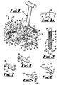
Fig 1 is a perspective view of a first embodiment of a surgical apparatus; -
Fig 1A is a side view of a support member forming part of the surgical apparatus shown inFig 1 ; -
Fig 2 is a sectional view of a mounting arrangement forming part of the surgical apparatus shown inFig 1 ; -
Figs 3 and 4 are perspective views of two retractors; -
Figs 5 and 6 are perspective views of first and second Hohman retractors; -
Fig 7 is a perspective view of a second embodiment of a surgical apparatus; -
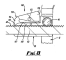
Fig 8 is a sectional view through the mounting arrangement shown inFig. 7 showing the rocker assembly; and -
Fig 9 is a perspective view of a third Hohman retractor - Referring to
Fig 1 , there is shown a first embodiment of asurgical apparatus 10 comprising a support member in the form of a generallysquare frame 12 comprising first and secondopposite sides opposite sides opposite sides opposite sides - A
first retractor 22 is mounted on thefirst side 14, and asecond retractor 24 is mounted on thesecond side 16. - A first mounting
arrangement 26 mounts thefirst retractor 22 on thefirst side 14, and a second mountingarrangement 28 mounts thesecond retractor 24 on thesecond side 16. - Referring to
Fig 1A there is shown a side view of thesupport member 12 in which thefirst side member 14 faces out of the paper. Thesecond side member 16 and the third andfourth side members first side member 14. Thefirst side member 12 comprises acentral region 30 andangled end regions central region 30 at an angle A of substantially 30°. It will be appreciated that thesecond side member 16 also includes acentral region 30 and first andsecond end regions central region 30. - The feature of the
end regions central region 30 of each of the first andsecond side members support member 12 follows the contours of the body on which the operation is effected. - The
support member 12 defines a generally squarecentral space 36 via which the operation can be carried out. - The first mounting
arrangement 26 comprises a displacement member in the form of anelongate rack 40. Theelongate rack 40 extends through ahousing 42 fixedly mounted on thefirst side 14. Apinion 44, shown in broken lines is provided in thehousing 42, and connected to awheel 46 by means of which thepinion 44 can be rotated. - The
rack 40 is provided with a plurality ofteeth 48 arranged adjacent one another along its length, and thepinion 44 includes a plurality of corresponding teeth arranged adjacent one another around the circumference of thepinion 44. - The teeth on the
pinion 44 engage theteeth 48 on therack 40 and upon rotation of thewheel 46 therack 40 can be moved linearly in and out of ahousing 42 in the directions shown by double headed arrow B inFig 1 . Thus, thefirst retractor 22 can be moved towards and away from thesecond retractor 24 by rotating thewheel 46. A lockingmember 50 having a lockingshaft 51, shown in broken lines inFig 1 , is provided on the side of thehousing 42. The lockingmember 50 is in the form of a bolt or screw and is threadably mounted on thehousing 42. When the lockingmember 50 is screwed into thehousing 42, it engages therack 40 to lock therack 40 in its position. - The first mounting
arrangement 26 also includes a first securingassembly 38 to which the respective first orsecond retractor assembly 38 is shown in section inFig 2 and comprises a fixedmember 52 through which a fastener in the form of abolt 54 extends. Thebolt 54 comprises ashaft 56, extending through the fixedmember 52, and ahead 58 to enable thebolt 54 to be rotated. Theshaft 56 is provided withthreads 60 along at least a part of its length along the end region opposite thehead 58. - A
movable member 62 threadably engages theshaft 56 such that when thebolt 54 is screwed into the fixedmember 52, the fixedmember 52 is tightened against themovable member 62. Themovable member 62 comprises a generally rectangularouter profile 64 which corresponds to the inner profile of a securingelement 66 of theretractor 22, as explained below. - Referring to
Figs 3 and 4 , there is shown examples of the first andsecond retractors retractors arrangements retractors retractor blade 66 and a securingelement 68 having a squareinternal profile 70. - The square
internal profile 70 of the securingelement 68 allows it to be slidably engaged on the square outer profile of themovable member 62 thereby preventing rotation of the retractor relative to themovable member 62. - The
movable member 62 and the fixedmember 52 are provided with respective interlockingformations 72 in the forms of serrations, to prevent relative rotation of themovable member 62 and the fixedmember 52 when they are engaged with each other. - The
blades 66 of the first andsecond retractors element 68 and are curved around the longitudinal axis of theblade 66. This provides a convex surface for engagement against soft tissue in the body, thereby reducing damage to such tissue. - Referring back to
Figs 1 and 2 , when thebolt 54 tightens themovable member 62 against the fixedmember 52, the interlockingformations 72 interlock with one another thereby preventing relative rotation. - Urging means in the form of a
spring 74 urges thebolt 54 in the direction indicated by the arrow C inFig 2 , thereby urging themovable member 62 against the fixedmember 52. Thus, by unscrewing thebolt 54, themovable member 62 can be moved away from the fixedmember 52 thereby disengaging the interlockingformations 72 from each other and allowing pivotal movement of themovable member 62 relative to the fixedmember 52. This allows theretractor 22 to be pivoted and, thus, positioned at the appropriate angle. - The
second retractor 24 is mounted on a second mountingarrangement 28. The second mountingarrangement 28 comprises the securingassembly 38. - The second mounting
arrangement 28 comprises a second securingassembly 39 which consists of the same features and operates in the same way as the first securingassembly 38 of the first mountingarrangement 26. - The
second securing assembly 39 differs from the first securingassembly 38 in that the second securingassembly 39 is fixedly attached to thesecond side 16 by anelongate bar 80 extending therefrom. Thebar 80 is fixedly attached to thesecond side 16 of thesupport member 12 bysuitable bolts 82. - The third and fourth sides of 80, 20 of the
support member 12 are provided with outwardly facingserrations 84 which allow a holdingmember 86 to be mounted in a desired position therealong. The holdingmember 86 comprisesupstanding projections 88 to which achain 90 can be secured. - The
chain 90 is attached to therespective Hohman retractor 100, as shown inFig 5 . -
Fig 5 shows two Hohman retractors, which could be used in surgery. Each of the Hohman retractors 100 comprises amain portion 102 and a softtissue engaging portion 104 extending from themain portion 102. At the opposite end of theHohman retractors 100 there is provided a securingportion 106 of a J shape having at its free end a securingpart 108 to which thechain 90 can be attached to secure the Hohman retractor 102 to the holdingmember 86. - First
removable handles 110 are provided on each of the first andsecond retractors retractors - Second
removable handles 112 can be provided on theHohman retractors 100 to position theHohman retractors 100 in the desired position. - In use, the
support member 12 is arranged over the hip of the patient undergoing the operation, and an incision is made through thespace 36 defined by thesupport member 12. - The use of the present embodiment provides the advantage that the incision need only be two or three centimetres in length, rather than, as with prior art surgical procedures ten to fifteen centimetres in length.
- Suitable first and
second retractors arrangements second retractors - The soft tissue surrounding the acetabulum can be retracted by the use of the
Hoh man retractors 102. - As can be seen from
Figs 3 and 4 the first andsecond retractor - There is thus described a simple and effective surgical apparatus which can be used in hip replacement or resurfacing surgery allowing minimally invasive hip surgery to be carried out thereby reducing the recovery time of the patient.
- Various modifications can be made without departing from the scope of the invention. For example, the handles used on the first and
second retractors - Referring to
Fig 7 , there is shown a second embodiment of asurgical apparatus 10, which comprises most of the features of the first embodiment shown inFig 1 and described above. InFig 7 , these features have been designated with the same reference numerals as inFig 1 , and operate in the same way as the corresponding features shown inFig 1 . - The
chains 90 securing theHohman retractors 100 to theframe 12 are omitted fromFig 7 for clarity. - The second embodiment of the
surgical apparatus 10 shown inFig 7 differs from the first embodiment shown inFig 1 in that the locking member is omitted. Instead, arocker assembly 140 is provided, which comprises depressible member in the form of arocker button 150. Therocker assembly 140 is shown in more detail inFig 8 - The
rocker button 150 is pivotally mounted in thehousing 42 by apivot member 152. Therocker button 150 has afirst region 154 on one side of the pivot, and asecond region 156 on the opposite side of thepivot 152. Thefirst region 154 includes anengaging element 155 to engage theteeth 48 of therack 40, as shown inFig 8 . InFig 8 , therocker button 150 is in its locking position, preventing any movement of therack 40 by thepinion 46. - An urging arrangement in the form of a
leaf spring 157 is provided integrally on therocker button 150. Theleaf spring 157 extends from thefirst region 154 of therocker button 150 along areaction portion 158 of the first mountingarrangement 26. - When the
rocker button 150 is depressed by pressing on thesecond region 156, the engagingelement 155 is pivoted away from theteeth 48 of therack 40, thereby disengaging the engaging element from theteeth 48 and moving therocker button 150 to a release position. - The
leaf spring 157 pushes against thereaction portion 158 and urges the rocker button to the locking position. Thus, when the user lets go of therocker button 150, theleaf spring 157 pushes against thereaction portion 158 to urge therocker button 150 towards the locking position to engage theteeth 48. -
Fig 9 shows athird retractor 160, which comprises the securingelement 68 having the squareinternal profile 70. Thethird retractor 160 also includes ablade 66. Aspike 162 extends from the securingelement 68 along theblade 66 to project therefrom at a projectingregion 164. Thespike 162 terminates at its free end at apoint 166. - Whilst endeavouring in the foregoing specification to draw attention to those features of the invention believed to be of particular importance it should be understood that the Applicant claims protection in respect of any patentable feature or combination of features hereinbefore referred to and/or shown in the drawings within the scope to the claims.
Claims (16)
- A surgical apparatus (10) comprising a support member (12) having first and second opposite sides (14,16); first and second retractors (22, 24) on the support member; a first mounting arrangement (26) on the first side, and a second mounting arrangement (28) on the second side; the first mounting arrangement being configured to mount the first retractor on the first side, wherein at least the first retractor is movable towards and away from the second retractor, and the second mounting arrangement being configured to mount the second retractor on the second side; and each mounting arrangement comprising a securing assembly (38, 39) to secure the first and second retractors to the first and second mounting arrangements respectively; wherein each securing assembly comprises a fixed member (52); a movable member (62) to which the first or second retractor can be secured; a fastener (54) extending through the fixed member, the fastener cooperatively engaging the fixed member; characterised by urging means (74) on the fastener to urge the movable member into engagement with the fixed member.
- A surgical apparatus according to Claim 1, wherein the fastener (54) comprises a head (58) and a shaft (56) having a threaded region, and the movable member (62) is threaded to threadably engage the shaft, and the movable member has a securing formation to secure the first or second retractor onto the movable member.
- A surgical apparatus according to Claim 1 or 2, wherein the first and second retractors (22, 24) face each other, and the first and second retractors are pivotally movable relative to the support member (12).
- A surgical apparatus according to Claim 1, 2 or 3, wherein the support member (12) defines an access region through which surgery can be effected, the support member (12) surrounding the afore said access region, and the retractors (22,24) extending through the access region.
- A surgical apparatus according to according to any preceding Claim, wherein each of the first and second sides (14, 16) comprises a central region (30) and opposite end regions (32, 34) extending transverse to the central region, the opposite end regions of each of the first and second sides being angled relative to the central region at an angle in the range of 20° to substantially 30° to the central region.
- A surgical apparatus according to Claim 5, wherein the support member (12) comprises opposite third and fourth sides (18, 20), the third and fourth sides extending between the first and second sides (14, 16) to connect the first side to the second side, thereby providing a generally rectangular profile of the support member, the third and fourth sides each including a movable holding member (86) to secure a respective surgical member (100) thereto, and the third and fourth sides further including serrations (84) to hold the holding member in a selected position on the respective third or fourth side.
- A surgical apparatus according to Claim 6, wherein each holding member (86) includes a securing formation to which a connecting element can be attached to connect the respective surgical member (100) to the holding member, the securing formation comprising an upstanding projection (88), and the connecting element is elongate, and each surgical member (100) comprises a respective manipulating member (110) to move the respective surgical member to its desired position.
- A surgical apparatus according to any preceding Claim, wherein the movable member (62) has interlocking formations, and the fixed member (52) has corresponding interlocking formations to co-operatively engage the interlocking formations on the movable member.
- A surgical apparatus according to any preceding Claim, wherein the movable member (62) includes a securing formation to secure the respective first or second retractor (22, 24) onto the movable member, the first and second retractors each comprising a securing element (68) slidably mounted on the securing formation to engage the respective movable member, and wherein the securing formation and the securing element are correspondingly configured to substantially prevent relative rotation of the movable member and the respective retractor.
- A surgical apparatus according to Claim 9, wherein the securing formation comprises a generally rectangular outer profile (64) of the movable member (62), and the securing element (68) has a generally rectangular inner profile (70), said inner profile of the securing element corresponding to the outer profile of the securing formation.
- A surgical apparatus according to any preceding Claim, wherein each of the movable members (62) is pivotally movable relative to the respective first or second fixed members (52) to arrange the respective first or second retractors (22, 24) at a desired angle relative to the support member (12).
- A surgical apparatus according to any preceding Claim, wherein the first mounting arrangement (26) comprises a displacement mechanism to move the first retractor (22) towards and away from the second retractor (24), the displacement mechanism comprising a displacement member to which the respective fixed member (52) is attached, the displacement member being elongate and comprising a rack (40), and the displacement mechanism further including a housing (42), through which the displacement member movably extends.
- A surgical apparatus according to Claim 12, wherein the first mounting arrangement (26) includes a driver to drive the displacement member, the driver comprising a rotatable head and a cog in engagement with the displacement member.
- A surgical apparatus according to Claim 12 or 13, wherein a locking member (50) is provided to lock the displacement member to the housing (42), the locking member comprising a threaded member threadably receivable in the housing to engage the mounting member, and the locking member further includes a rotatable head mounted on the threaded member to rotate the threaded member.
- A surgical apparatus according to Claim 12 or 13, wherein a locking member is provided to lock the displacement member to the housing (42), the locking member comprising a depressible member (150) for engaging the displacement member, the depressible member being movable between a locking position and a release position by pressing thereon.
- A surgical apparatus according to Claim 15, wherein the depressible member (150) can pivot about a pivot member (152) between the locking and the release positions, the depressible element being depressible at a first region (154) on one side of the pivot member to move the depressible element to the locking position, and the depressible element is depressible at a second region (156) on the opposite side of the pivot member to move the depressible member to the release position.
Applications Claiming Priority (2)
| Application Number | Priority Date | Filing Date | Title |
|---|---|---|---|
| GBGB0608561.7A GB0608561D0 (en) | 2006-04-29 | 2006-04-29 | Surgical apparatus |
| PCT/GB2007/001570 WO2007125348A1 (en) | 2006-04-29 | 2007-04-30 | Surgical apparatus |
Publications (2)
| Publication Number | Publication Date |
|---|---|
| EP2029030A1 EP2029030A1 (en) | 2009-03-04 |
| EP2029030B1 true EP2029030B1 (en) | 2010-11-10 |
Family
ID=36590095
Family Applications (1)
| Application Number | Title | Priority Date | Filing Date |
|---|---|---|---|
| EP07732604A Not-in-force EP2029030B1 (en) | 2006-04-29 | 2007-04-30 | Surgical apparatus |
Country Status (7)
| Country | Link |
|---|---|
| US (1) | US20090264710A1 (en) |
| EP (1) | EP2029030B1 (en) |
| AT (1) | ATE487426T1 (en) |
| AU (1) | AU2007245419A1 (en) |
| DE (1) | DE602007010455D1 (en) |
| GB (1) | GB0608561D0 (en) |
| WO (1) | WO2007125348A1 (en) |
Families Citing this family (21)
| Publication number | Priority date | Publication date | Assignee | Title |
|---|---|---|---|---|
| US9795367B1 (en) | 2003-10-17 | 2017-10-24 | Nuvasive, Inc. | Surgical access system and related methods |
| US9486133B2 (en) | 2010-08-23 | 2016-11-08 | Nuvasive, Inc. | Surgical access system and related methods |
| US9655505B1 (en) | 2012-02-06 | 2017-05-23 | Nuvasive, Inc. | Systems and methods for performing neurophysiologic monitoring during spine surgery |
| US9066701B1 (en) | 2012-02-06 | 2015-06-30 | Nuvasive, Inc. | Systems and methods for performing neurophysiologic monitoring during spine surgery |
| US9757067B1 (en) | 2012-11-09 | 2017-09-12 | Nuvasive, Inc. | Systems and methods for performing neurophysiologic monitoring during spine surgery |
| CN103190936B (en) * | 2013-03-11 | 2015-08-05 | 温州医科大学附属第二医院 | Cervical spine breast section anterior minimally invasive automatic drag hook for operation device |
| AU2015229719B2 (en) | 2014-03-10 | 2017-04-06 | Stryker Corporation | Limb positioning system |
| EP3692935B1 (en) | 2014-04-23 | 2023-06-28 | Applied Medical Resources Corporation | Systems for tissue removal |
| KR102462961B1 (en) | 2014-08-18 | 2022-11-03 | 어플라이드 메디컬 리소시스 코포레이션 | Systems and methods for tissue containment and retrieval |
| KR20250030011A (en) | 2014-11-13 | 2025-03-05 | 어플라이드 메디컬 리소시스 코포레이션 | Systems and methods for tissue removal |
| US9848863B2 (en) | 2015-02-25 | 2017-12-26 | Globus Medical, Inc | Surgical retractor systems and methods |
| US9951904B2 (en) | 2015-03-24 | 2018-04-24 | Stryker Corporation | Rotatable seat clamps for rail clamp |
| EP3900653B1 (en) | 2015-04-23 | 2024-07-24 | Applied Medical Resources Corporation | Systems for tissue removal |
| US9700293B2 (en) | 2015-08-18 | 2017-07-11 | Globus Medical, Inc. | Devices and systems for surgical retraction |
| ES3023515T3 (en) | 2016-01-22 | 2025-06-02 | Applied Med Resources | Systems for tissue removal |
| CN106388883B (en) * | 2016-08-31 | 2024-05-07 | 张强 | Arthroscopic auxiliary retractor |
| US10786328B2 (en) * | 2016-10-26 | 2020-09-29 | Thompson Surgical Instruments, Inc. | Adaptor handle for surgical retractor |
| AU2019343947B2 (en) | 2018-09-20 | 2025-05-08 | Applied Medical Resources Corporation | Tissue removal containment systems |
| RU194917U1 (en) * | 2019-08-05 | 2019-12-30 | Частное учреждение образовательная организация высшего образования "Медицинский университет "Реавиз" | SURGERY EXPANDER |
| RU194175U1 (en) * | 2019-08-05 | 2019-11-29 | Частное учреждение образовательная организация высшего образования "Медицинский университет "Реавиз" | OPERATOR FOR INTERVENTION |
| RU2717894C1 (en) * | 2019-08-12 | 2020-03-26 | Частное учреждение образовательная организация высшего образования "Медицинский университет "Реавиз" | Retractor for surgical intervention |
Family Cites Families (17)
| Publication number | Priority date | Publication date | Assignee | Title |
|---|---|---|---|---|
| US4718151A (en) * | 1984-11-08 | 1988-01-12 | Minnesota Scientific, Inc. | Retractor apparatus |
| US4971037A (en) * | 1988-09-19 | 1990-11-20 | Pilling Co. | Surgical retractor support |
| US5237996A (en) * | 1992-02-11 | 1993-08-24 | Waldman Lewis K | Endocardial electrical mapping catheter |
| US6431025B1 (en) * | 1996-08-30 | 2002-08-13 | Tibor Koros | Ratchet mechanism for a surgical retractor assembly |
| US5882298A (en) * | 1998-08-05 | 1999-03-16 | Minnesota Scientific, Inc. | Retractor assembly with connecting pin and method for removably assembling |
| US6190312B1 (en) * | 1999-03-04 | 2001-02-20 | Lone Star Medical Products, Inc. | Variable geometry retractor and disposable retractor stay clips and method of use |
| US6685632B1 (en) | 1999-05-04 | 2004-02-03 | Cardiothoracic Systems, Inc. | Surgical instruments for accessing and stabilizing a localized portion of a beating heart |
| US6616664B2 (en) * | 1999-10-21 | 2003-09-09 | Ebi L.P. | Clamp assembly for an external fixation system |
| US6302915B1 (en) * | 2000-08-30 | 2001-10-16 | The Mayo Foundation For Medical Education & Research | Ulnar implant system |
| US6945933B2 (en) * | 2002-06-26 | 2005-09-20 | Sdgi Holdings, Inc. | Instruments and methods for minimally invasive tissue retraction and surgery |
| AU2003295934B2 (en) * | 2002-11-23 | 2009-02-26 | Frey, George A. | Distraction and retraction system for spinal surgery |
| US7156805B2 (en) * | 2003-03-31 | 2007-01-02 | Depuy Spine, Inc. | Surgical retractor |
| US7338442B2 (en) * | 2003-04-02 | 2008-03-04 | Peak Performance Company | Crank retractor handle |
| WO2005037089A1 (en) * | 2003-10-17 | 2005-04-28 | Minnesota Scientific, Inc. | Articulated retractor blade holder |
| US20060224044A1 (en) * | 2005-03-31 | 2006-10-05 | Depuy Spine, Inc. | Surgical retractors and methods of use |
| EP1988814B1 (en) * | 2006-03-01 | 2014-07-02 | Boss Instruments, Ltd. | Surgical retractor frame system |
| US7871426B2 (en) * | 2006-03-21 | 2011-01-18 | Spinefrontier, LLS | Spinous process fixation device |
-
2006
- 2006-04-29 GB GBGB0608561.7A patent/GB0608561D0/en not_active Ceased
-
2007
- 2007-04-30 DE DE602007010455T patent/DE602007010455D1/en active Active
- 2007-04-30 AT AT07732604T patent/ATE487426T1/en not_active IP Right Cessation
- 2007-04-30 US US12/296,925 patent/US20090264710A1/en not_active Abandoned
- 2007-04-30 WO PCT/GB2007/001570 patent/WO2007125348A1/en not_active Ceased
- 2007-04-30 AU AU2007245419A patent/AU2007245419A1/en not_active Abandoned
- 2007-04-30 EP EP07732604A patent/EP2029030B1/en not_active Not-in-force
Also Published As
| Publication number | Publication date |
|---|---|
| AU2007245419A1 (en) | 2007-11-08 |
| ATE487426T1 (en) | 2010-11-15 |
| WO2007125348A1 (en) | 2007-11-08 |
| EP2029030A1 (en) | 2009-03-04 |
| DE602007010455D1 (en) | 2010-12-23 |
| GB0608561D0 (en) | 2006-06-07 |
| US20090264710A1 (en) | 2009-10-22 |
Similar Documents
| Publication | Publication Date | Title |
|---|---|---|
| US20090264710A1 (en) | Surgical apparatus | |
| US10799228B2 (en) | Modular retractor and related method | |
| US8206293B2 (en) | Retractor | |
| US10548600B2 (en) | Multiple thickness implantable layers for surgical stapling devices | |
| US8956285B2 (en) | Retraction apparatus and method of use | |
| US8262570B2 (en) | Retraction apparatus and method of use | |
| JP6293793B2 (en) | Surgical end effector having a removable material layer and the same material layer | |
| RU2658454C2 (en) | Multiple thickness implantable layers for surgical stapling devices | |
| US10052143B2 (en) | Tensioning instrument and related bone fixation systems and methods | |
| US8900137B1 (en) | Cervical retractor | |
| US7011658B2 (en) | Devices and methods for spinal compression and distraction | |
| US20070208228A1 (en) | Surgical retractors and methods of minimally invasive surgery | |
| CN100488462C (en) | Instruments and methods for minimal invasive tissue retraction and surgery | |
| US20070156025A1 (en) | Surgical retractors and methods of minimally invasive surgery | |
| WO2005070329A3 (en) | Combined distractor and retractor instrument | |
| CN106913362B (en) | End effector and its nail kit part, surgical operating instrument | |
| EP1499244A1 (en) | Retractor | |
| US11957329B2 (en) | Self-retaining retractor | |
| US9259213B1 (en) | Retractor | |
| EP2192861B1 (en) | Surgical retractor | |
| EP4464274A1 (en) | Arm attachment for retractor and retractor blades | |
| JP6321043B2 (en) | Actuator for releasing a layer of material from a surgical end effector | |
| WO2007068128A1 (en) | A pair of tongs apt for soft tissue spreading | |
| US20220395999A1 (en) | Devices for Maintaining Tension in Chain Saws |
Legal Events
| Date | Code | Title | Description |
|---|---|---|---|
| PUAI | Public reference made under article 153(3) epc to a published international application that has entered the european phase |
Free format text: ORIGINAL CODE: 0009012 |
|
| 17P | Request for examination filed |
Effective date: 20081107 |
|
| AK | Designated contracting states |
Kind code of ref document: A1 Designated state(s): AT BE BG CH CY CZ DE DK EE ES FI FR GB GR HU IE IS IT LI LT LU LV MC MT NL PL PT RO SE SI SK TR |
|
| AX | Request for extension of the european patent |
Extension state: AL BA HR MK RS |
|
| 17Q | First examination report despatched |
Effective date: 20090812 |
|
| GRAP | Despatch of communication of intention to grant a patent |
Free format text: ORIGINAL CODE: EPIDOSNIGR1 |
|
| GRAS | Grant fee paid |
Free format text: ORIGINAL CODE: EPIDOSNIGR3 |
|
| GRAA | (expected) grant |
Free format text: ORIGINAL CODE: 0009210 |
|
| AK | Designated contracting states |
Kind code of ref document: B1 Designated state(s): AT BE BG CH CY CZ DE DK EE ES FI FR GB GR HU IE IS IT LI LT LU LV MC MT NL PL PT RO SE SI SK TR |
|
| REG | Reference to a national code |
Ref country code: GB Ref legal event code: FG4D |
|
| REG | Reference to a national code |
Ref country code: CH Ref legal event code: EP |
|
| REG | Reference to a national code |
Ref country code: IE Ref legal event code: FG4D |
|
| REF | Corresponds to: |
Ref document number: 602007010455 Country of ref document: DE Date of ref document: 20101223 Kind code of ref document: P |
|
| REG | Reference to a national code |
Ref country code: NL Ref legal event code: VDEP Effective date: 20101110 |
|
| LTIE | Lt: invalidation of european patent or patent extension |
Effective date: 20101110 |
|
| PG25 | Lapsed in a contracting state [announced via postgrant information from national office to epo] |
Ref country code: LT Free format text: LAPSE BECAUSE OF FAILURE TO SUBMIT A TRANSLATION OF THE DESCRIPTION OR TO PAY THE FEE WITHIN THE PRESCRIBED TIME-LIMIT Effective date: 20101110 |
|
| PG25 | Lapsed in a contracting state [announced via postgrant information from national office to epo] |
Ref country code: SE Free format text: LAPSE BECAUSE OF FAILURE TO SUBMIT A TRANSLATION OF THE DESCRIPTION OR TO PAY THE FEE WITHIN THE PRESCRIBED TIME-LIMIT Effective date: 20101110 Ref country code: AT Free format text: LAPSE BECAUSE OF FAILURE TO SUBMIT A TRANSLATION OF THE DESCRIPTION OR TO PAY THE FEE WITHIN THE PRESCRIBED TIME-LIMIT Effective date: 20101110 Ref country code: FI Free format text: LAPSE BECAUSE OF FAILURE TO SUBMIT A TRANSLATION OF THE DESCRIPTION OR TO PAY THE FEE WITHIN THE PRESCRIBED TIME-LIMIT Effective date: 20101110 Ref country code: CY Free format text: LAPSE BECAUSE OF FAILURE TO SUBMIT A TRANSLATION OF THE DESCRIPTION OR TO PAY THE FEE WITHIN THE PRESCRIBED TIME-LIMIT Effective date: 20101110 Ref country code: BG Free format text: LAPSE BECAUSE OF FAILURE TO SUBMIT A TRANSLATION OF THE DESCRIPTION OR TO PAY THE FEE WITHIN THE PRESCRIBED TIME-LIMIT Effective date: 20110210 Ref country code: IS Free format text: LAPSE BECAUSE OF FAILURE TO SUBMIT A TRANSLATION OF THE DESCRIPTION OR TO PAY THE FEE WITHIN THE PRESCRIBED TIME-LIMIT Effective date: 20110310 Ref country code: PT Free format text: LAPSE BECAUSE OF FAILURE TO SUBMIT A TRANSLATION OF THE DESCRIPTION OR TO PAY THE FEE WITHIN THE PRESCRIBED TIME-LIMIT Effective date: 20110310 Ref country code: NL Free format text: LAPSE BECAUSE OF FAILURE TO SUBMIT A TRANSLATION OF THE DESCRIPTION OR TO PAY THE FEE WITHIN THE PRESCRIBED TIME-LIMIT Effective date: 20101110 Ref country code: LV Free format text: LAPSE BECAUSE OF FAILURE TO SUBMIT A TRANSLATION OF THE DESCRIPTION OR TO PAY THE FEE WITHIN THE PRESCRIBED TIME-LIMIT Effective date: 20101110 Ref country code: SI Free format text: LAPSE BECAUSE OF FAILURE TO SUBMIT A TRANSLATION OF THE DESCRIPTION OR TO PAY THE FEE WITHIN THE PRESCRIBED TIME-LIMIT Effective date: 20101110 |
|
| PG25 | Lapsed in a contracting state [announced via postgrant information from national office to epo] |
Ref country code: GR Free format text: LAPSE BECAUSE OF FAILURE TO SUBMIT A TRANSLATION OF THE DESCRIPTION OR TO PAY THE FEE WITHIN THE PRESCRIBED TIME-LIMIT Effective date: 20110211 |
|
| PG25 | Lapsed in a contracting state [announced via postgrant information from national office to epo] |
Ref country code: BE Free format text: LAPSE BECAUSE OF FAILURE TO SUBMIT A TRANSLATION OF THE DESCRIPTION OR TO PAY THE FEE WITHIN THE PRESCRIBED TIME-LIMIT Effective date: 20101110 Ref country code: ES Free format text: LAPSE BECAUSE OF FAILURE TO SUBMIT A TRANSLATION OF THE DESCRIPTION OR TO PAY THE FEE WITHIN THE PRESCRIBED TIME-LIMIT Effective date: 20110221 Ref country code: EE Free format text: LAPSE BECAUSE OF FAILURE TO SUBMIT A TRANSLATION OF THE DESCRIPTION OR TO PAY THE FEE WITHIN THE PRESCRIBED TIME-LIMIT Effective date: 20101110 Ref country code: CZ Free format text: LAPSE BECAUSE OF FAILURE TO SUBMIT A TRANSLATION OF THE DESCRIPTION OR TO PAY THE FEE WITHIN THE PRESCRIBED TIME-LIMIT Effective date: 20101110 |
|
| PGFP | Annual fee paid to national office [announced via postgrant information from national office to epo] |
Ref country code: GB Payment date: 20110307 Year of fee payment: 5 Ref country code: DE Payment date: 20110317 Year of fee payment: 5 |
|
| PG25 | Lapsed in a contracting state [announced via postgrant information from national office to epo] |
Ref country code: RO Free format text: LAPSE BECAUSE OF FAILURE TO SUBMIT A TRANSLATION OF THE DESCRIPTION OR TO PAY THE FEE WITHIN THE PRESCRIBED TIME-LIMIT Effective date: 20101110 Ref country code: PL Free format text: LAPSE BECAUSE OF FAILURE TO SUBMIT A TRANSLATION OF THE DESCRIPTION OR TO PAY THE FEE WITHIN THE PRESCRIBED TIME-LIMIT Effective date: 20101110 Ref country code: DK Free format text: LAPSE BECAUSE OF FAILURE TO SUBMIT A TRANSLATION OF THE DESCRIPTION OR TO PAY THE FEE WITHIN THE PRESCRIBED TIME-LIMIT Effective date: 20101110 Ref country code: SK Free format text: LAPSE BECAUSE OF FAILURE TO SUBMIT A TRANSLATION OF THE DESCRIPTION OR TO PAY THE FEE WITHIN THE PRESCRIBED TIME-LIMIT Effective date: 20101110 |
|
| PLBE | No opposition filed within time limit |
Free format text: ORIGINAL CODE: 0009261 |
|
| STAA | Information on the status of an ep patent application or granted ep patent |
Free format text: STATUS: NO OPPOSITION FILED WITHIN TIME LIMIT |
|
| 26N | No opposition filed |
Effective date: 20110811 |
|
| PG25 | Lapsed in a contracting state [announced via postgrant information from national office to epo] |
Ref country code: MC Free format text: LAPSE BECAUSE OF NON-PAYMENT OF DUE FEES Effective date: 20110430 |
|
| REG | Reference to a national code |
Ref country code: CH Ref legal event code: PL |
|
| REG | Reference to a national code |
Ref country code: DE Ref legal event code: R097 Ref document number: 602007010455 Country of ref document: DE Effective date: 20110811 |
|
| PG25 | Lapsed in a contracting state [announced via postgrant information from national office to epo] |
Ref country code: IT Free format text: LAPSE BECAUSE OF FAILURE TO SUBMIT A TRANSLATION OF THE DESCRIPTION OR TO PAY THE FEE WITHIN THE PRESCRIBED TIME-LIMIT Effective date: 20101110 Ref country code: MT Free format text: LAPSE BECAUSE OF FAILURE TO SUBMIT A TRANSLATION OF THE DESCRIPTION OR TO PAY THE FEE WITHIN THE PRESCRIBED TIME-LIMIT Effective date: 20101110 |
|
| REG | Reference to a national code |
Ref country code: FR Ref legal event code: ST Effective date: 20111230 |
|
| PG25 | Lapsed in a contracting state [announced via postgrant information from national office to epo] |
Ref country code: FR Free format text: LAPSE BECAUSE OF NON-PAYMENT OF DUE FEES Effective date: 20110502 Ref country code: CH Free format text: LAPSE BECAUSE OF NON-PAYMENT OF DUE FEES Effective date: 20110430 Ref country code: LI Free format text: LAPSE BECAUSE OF NON-PAYMENT OF DUE FEES Effective date: 20110430 |
|
| REG | Reference to a national code |
Ref country code: IE Ref legal event code: MM4A |
|
| PG25 | Lapsed in a contracting state [announced via postgrant information from national office to epo] |
Ref country code: IE Free format text: LAPSE BECAUSE OF NON-PAYMENT OF DUE FEES Effective date: 20110430 |
|
| GBPC | Gb: european patent ceased through non-payment of renewal fee |
Effective date: 20120430 |
|
| PG25 | Lapsed in a contracting state [announced via postgrant information from national office to epo] |
Ref country code: GB Free format text: LAPSE BECAUSE OF NON-PAYMENT OF DUE FEES Effective date: 20120430 |
|
| REG | Reference to a national code |
Ref country code: DE Ref legal event code: R119 Ref document number: 602007010455 Country of ref document: DE Effective date: 20121101 |
|
| PG25 | Lapsed in a contracting state [announced via postgrant information from national office to epo] |
Ref country code: LU Free format text: LAPSE BECAUSE OF NON-PAYMENT OF DUE FEES Effective date: 20110430 |
|
| PG25 | Lapsed in a contracting state [announced via postgrant information from national office to epo] |
Ref country code: TR Free format text: LAPSE BECAUSE OF FAILURE TO SUBMIT A TRANSLATION OF THE DESCRIPTION OR TO PAY THE FEE WITHIN THE PRESCRIBED TIME-LIMIT Effective date: 20101110 |
|
| PG25 | Lapsed in a contracting state [announced via postgrant information from national office to epo] |
Ref country code: HU Free format text: LAPSE BECAUSE OF FAILURE TO SUBMIT A TRANSLATION OF THE DESCRIPTION OR TO PAY THE FEE WITHIN THE PRESCRIBED TIME-LIMIT Effective date: 20101110 |
|
| PG25 | Lapsed in a contracting state [announced via postgrant information from national office to epo] |
Ref country code: DE Free format text: LAPSE BECAUSE OF NON-PAYMENT OF DUE FEES Effective date: 20121101 |