EP2028717A1 - Multi-band antenna apparatus disposed on a three-dimensional substrate - Google Patents
Multi-band antenna apparatus disposed on a three-dimensional substrate Download PDFInfo
- Publication number
- EP2028717A1 EP2028717A1 EP07114887A EP07114887A EP2028717A1 EP 2028717 A1 EP2028717 A1 EP 2028717A1 EP 07114887 A EP07114887 A EP 07114887A EP 07114887 A EP07114887 A EP 07114887A EP 2028717 A1 EP2028717 A1 EP 2028717A1
- Authority
- EP
- European Patent Office
- Prior art keywords
- antenna
- substrate
- strip
- radiation element
- band
- Prior art date
- Legal status (The legal status is an assumption and is not a legal conclusion. Google has not performed a legal analysis and makes no representation as to the accuracy of the status listed.)
- Granted
Links
Images





Classifications
-
- H—ELECTRICITY
- H01—ELECTRIC ELEMENTS
- H01Q—ANTENNAS, i.e. RADIO AERIALS
- H01Q9/00—Electrically-short antennas having dimensions not more than twice the operating wavelength and consisting of conductive active radiating elements
- H01Q9/04—Resonant antennas
- H01Q9/30—Resonant antennas with feed to end of elongated active element, e.g. unipole
- H01Q9/40—Element having extended radiating surface
-
- H—ELECTRICITY
- H01—ELECTRIC ELEMENTS
- H01Q—ANTENNAS, i.e. RADIO AERIALS
- H01Q1/00—Details of, or arrangements associated with, antennas
- H01Q1/36—Structural form of radiating elements, e.g. cone, spiral, umbrella; Particular materials used therewith
- H01Q1/38—Structural form of radiating elements, e.g. cone, spiral, umbrella; Particular materials used therewith formed by a conductive layer on an insulating support
-
- H—ELECTRICITY
- H01—ELECTRIC ELEMENTS
- H01Q—ANTENNAS, i.e. RADIO AERIALS
- H01Q5/00—Arrangements for simultaneous operation of antennas on two or more different wavebands, e.g. dual-band or multi-band arrangements
- H01Q5/30—Arrangements for providing operation on different wavebands
- H01Q5/307—Individual or coupled radiating elements, each element being fed in an unspecified way
- H01Q5/342—Individual or coupled radiating elements, each element being fed in an unspecified way for different propagation modes
- H01Q5/357—Individual or coupled radiating elements, each element being fed in an unspecified way for different propagation modes using a single feed point
-
- H—ELECTRICITY
- H01—ELECTRIC ELEMENTS
- H01Q—ANTENNAS, i.e. RADIO AERIALS
- H01Q9/00—Electrically-short antennas having dimensions not more than twice the operating wavelength and consisting of conductive active radiating elements
- H01Q9/04—Resonant antennas
- H01Q9/30—Resonant antennas with feed to end of elongated active element, e.g. unipole
- H01Q9/42—Resonant antennas with feed to end of elongated active element, e.g. unipole with folded element, the folded parts being spaced apart a small fraction of the operating wavelength
Definitions
- the present invention relates generally to an antenna construction for a mobile station, or other radio device, operable over multiple frequency bands. More particularly, the present invention relates to antenna apparatus, and an associated methodology for forming a hybrid strip antenna of a multi-mode mobile station, or other radio device, operable, e.g., at the 800/900/1800/1900/2100 MHz frequency bands.
- the antenna includes radiation elements comprising a strip including an impedance matching element disposed upon the external surfaces of a three-dimensional rectilinear substrate, such as a parallelepiped, cube, or pyramidal frustum.
- the length of the strip is chosen to efficiently transduce RF energy in at least one frequency band of as many as four or more frequency bands. Since a relatively long strip antenna is wound around a very compact substrate, the antenna is of compact dimensions and exhibits stable and relatively wide resonant frequency band characteristics and radiation patterns.
- Radio communication systems In modem society, the ready availability and access to mobile radio communication systems through which to communicate is a practical necessity.
- Cellular, and cellular-like, communication systems are exemplary radio communication systems whose infrastructures have been widely deployed and regularly utilized by many.
- Successive generations of cellular communication systems have been developed, and their operating parameters and protocols are set forth in standards promulgated by standard-setting bodies. And, successive generations of network apparatus have been deployed, each operable in conformity with an associated operating standard.
- Early-generation cellular communication systems provided voice communication services and limited data communication services.
- Successor-generation, cellular communication systems provide increasingly data-intensive communication services.
- Differing operating standards not only provide different communication capabilities, but utilize different communication technologies and differing frequencies of operation in different frequency bands.
- the installation of different types of cellular communication systems is sometimes geographically dependent. That is to say, in different areas, network infrastructures, operable pursuant to different types of operating standards, are deployed. The network infrastructures deployed in the different areas are not necessarily compatible.
- a mobile station operable to communicate by way of network infrastructure constructed in conformity with one operating specification is not necessarily operable to communicate by way of network infrastructure operable pursuant to another operating standard.
- multi-mode mobile stations have been developed that provide the mobile station with communication capability in more than one, i.e., multiple, communication systems, which also operate at different frequencies in different frequency bands.
- multi-mode mobile stations automatically select the manner by which the mobile station is to be operable, responsive to the detected network infrastructure in whose coverage area that the mobile station is positioned. If positioned in the coverage area of the network infrastructures of more than one type of communication system with which the mobile station is capable of communicating, selection of a network infrastructure through which to communicate is made pursuant to a preference scheme, or manually.
- the mobile station When provided with multi-mode capability, the mobile station contains circuitry and circuit elements permitting its operation to communicate pursuant to each of the communication systems.
- a multi-mode mobile station is formed of separate circuitry, separately operable to communicate pursuant to the different operating standards.
- circuit elements of the different circuit paths can be shared, parts of the separate circuit paths are constructed to be intertwined, or otherwise shared.
- Sharing of antenna transducer elements between the different circuit paths presents unique challenges. The required size of an antenna transducer element is, in part, dependent upon the frequencies of the signal energy that is to be transduced by the transducer element.
- antenna transducer design becomes increasingly difficult, particularly in multi-mode mobile stations when the different modes operate at different frequencies.
- Significant effort has been exerted to construct an antenna transducer, operable over multiple frequency bands, and also of small dimension to permit its positioning within the housing of a mobile station of compact size.
- a PIFA Planar Inverted-F Antenna
- PIFA antennas have narrow bandwidths.
- the structure of the PIFA is sometimes combined together with a parasitic element, or a multi-layered, three-dimensional structure.
- Such additions however, increase the volumetric dimensions of the antenna, as well as its weight.
- the additional resonant branches make the antenna difficult to tune and sometimes introduce EMC and EMI, which interferes with transducing of signal energy.
- Figure 1 illustrates a functional block diagram of a radio communication system in which an embodiment of the present invention is operable.
- Figure 2 illustrates a perspective view of an embodiment of the present invention.
- Figure 3 illustrates a close-up perspective view of the embodiment depicted in Figure 2 .
- Figure 4 illustrates another close-up perspective view of the embodiment depicted in Figure 2 but viewed from a different direction than shown in Figure 3 .
- Figure 5 illustrates a plan view of the antenna depicted in Figure 2 with the faces of the substrate unfolded and depicting antenna current flow in the two low or fundamental frequency bands of 800 and 900 MHz.
- Figure 6 illustrates a plan view of the antenna depicted in Figure 2 with the faces of the substrate unfolded as in Figure 5 but instead depicting antenna current flow in the high fundamental frequency bands of 1800 and 1900 MHz.
- Figures 7A and 7B illustrate radiation patterns of the antenna shown in Figure 2 in two orthogonal planes, at two different frequencies.
- Figure 8 illustrates a plot of the antenna's return loss as a function of an input signal frequency.
- Figure 9 illustrates a method flow diagram in accordance with an embodiment of the present invention.
- the present invention accordingly, advantageously provides compact, lightweight antenna apparatus, and an associated method, for a mobile station, or other radio device, operable over multiple frequency bands.
- a manner is provided by which to form a hybrid strip antenna of a multi-mode mobile station, or other radio device, operable, e.g., at the 800/900/1800/1900 MHz frequency bands.
- an antenna for a multi-mode mobile station is formed of a cube-shaped dielectric antenna substrate, the surfaces of which carry an end-fed antenna strip, formed of a strip of metal or other conductive material having a length, width and thickness.
- the length of the strip is much longer than the dimensions of any one face of the antenna substrate, requiring the strip to be folded at least part way over different faces of the antenna substrate. In other words, the length of the antenna strip is multiples of the dimensions of any one face of the cube.
- the antenna includes a feed point at one end of the strip and a "T"-shaped impedance matching/adjustment element at the end of the strip opposite the feed point.
- the cube dimensions and the length and width of the radiation element are selected so that the radiation element can be "folded” across or “wrapped” around several faces of the cube without the radiation element overlapping itself and without the edges of the radiation element abutting each other.
- the cube dimensions are also selected so that the cube can fit within the housing of a mobile station.
- the length of the strip forming the antenna element was approximately one-quarter the wavelength of a signal in the 800 MHz frequency band, and it effectuated resonance in both the 800 and 900 MHz bands.
- the antenna was also resonant in the 1800, 1900 and 2100 MHz bands.
- the strip forming the radiation element can be thought of, and also described as, several different substantially equallength conductive segments that are electrically connected to each other in series. Successive segments are joined to each other on the cube face such that each segment's length dimension is orthogonal to the length dimension of adjacent segments. In the embodiments shown, each cube face supports more than one antenna segment. The impedance matching element at the terminus end of the strip is also folded across cube faces.
- the antenna is advantageously utilized in a mobile station, or other radio device, of small volumetric dimensions.
- a folded strip antenna and an associated methodology is provided for a multi-band communication device.
- the folded strip antenna is embodied by forming a dielectric material into the shape of a cube.
- a radiation element such as a thin, flat metal strip, has a length and width such that the strip can be folded to extend at least part way across several of the different faces of the cube.
- a radio communication system shown generally at 10, provides for radio communications with mobile stations, of which the mobile station 12 is representative.
- the mobile station 12 is here representative of a quad-mode mobile station, capable of communicating at the 800/900/1800/1900 MHz frequency bands.
- Such a mobile station is sometimes referred to as a world-band mobile station as the mobile station is operable in conformity with the operating specifications and protocols of the cellular communication systems that presently are predominant.
- the mobile station is representative of various radio devices that are operable over multiple bands or large bandwidths at relatively high frequencies.
- Radio access networks 14, 16, 18, and 22 are representative of four radio networks operable respectively at the 800, 900, 1800, and 1900 MHz frequency bands, respectively.
- the mobile station 12 When the mobile station 12 is positioned within the coverage area of any of the radio access networks 14-22, the mobile station is capable of communicating therewith. If the separate networks have overlapping coverage areas, then the selection is made as to which of the networks through which to communicate.
- the radio access networks 14-22 are coupled, here by way of gateways (GWYs) 26 to a core network 28.
- GWYs gateways
- CE communication endpoint
- the mobile station 12 includes a radio transceiver having transceiver circuitry 36 capable of transceiving communication signals with any of the networks 14-22.
- the transceiver circuitry includes separate or shared transceiver paths constructed to be operable with the operating standards and protocols of the respective networks.
- the radio station further includes an antenna 50 of an embodiment of the present invention.
- the antenna is of characteristics to be operable at the different frequency bands at which the transceiver circuitry and the radio access networks are operable.
- the antenna 50 is operable at the 800, 900, 1800, and 1900 MHz frequency bands.
- the antenna 50 is housed together with the transceiver circuitry, in a housing 44 of the mobile station. As the space within the housing that is available to house the antenna is limited, the dimensions of the antenna 50 are correspondingly small while providing for the transducing of signal energy by the antenna over broad frequencies at which the mobile station is operable.
- FIG 2 illustrates an exemplary implementation of a multi-band strip antenna 50 for the multi-band communications device 12, depicted in Figure 1 .
- the multi-band strip antenna 50 is comprised of a dielectric antenna substrate 52 having the shape of right rectangular parallelepiped but which is also accurately described as a type of three-dimensional rectilinear body.
- the parallelepiped-shaped antenna substrate 52 shown in Figure 2 is more commonly known as a cube, which of course has six rectangular, i.e., square, sides, denominated here as a top face 64, bottom face 66 and four side faces 68, 70, 72 and 74 that extend between corresponding edges of the top face 64 and bottom face 66.
- the top face 64 and bottom face 66 are planar or at least substantially planar and lie in corresponding parallel but spaced-apart geometric planes, the separation distance of which defines the height, H, of the cube.
- the side faces 68, 70, 72 and 74 of the antenna substrate 52 are also planar or substantially planar and orthogonal to the top face 64 and the bottom face 66 with faces adjacent to each other also being orthogonal to each other.
- the antenna 50 is depicted atop a substantially planar dielectric supporting substrate 76 to which a metal ground plane 78 is also attached.
- the ground plane 78 acts to shield circuitry of the device 12 from signals emitted from the antenna as well as electromagnetic interference or EMI from external sources.
- the ground plane 78 also shapes the radiation pattern of the antenna 50.
- a three-dimensional rectilinear antenna substrate 52 depicted is fabricated as a solid piece of molded dielectric material, in which case, the substrate will of course have multiple sides. A cube-shaped substrate 52 will have six sides. In embodiments where the antenna substrate 52 is solid, the bottom face 66 of the substrate 52 will abut a surface of the supporting substrate 76 when the antenna substrate 52 is mounted atop a supporting substrate 76. Since a solid substrate 52 will add weight and cost, in at least one other embodiment, the three-dimensional rectilinear antenna substrate 52 is not solid but is instead constructed from one or more separate panels of dielectric material that is folded into a desired shape for the antenna substrate 52. In yet another embodiment, the parallelepiped is constructed from several separate discrete panels affixed to each other. Various well-known methods of attachment can be used including, but not limited to, adhesives, heat, ultrasonic welding or mechanical fasteners.
- a cube-shaped antenna substrate 52 can have either five or six sides, the construction of which is referred to herein as being a panelized substrate.
- a panelized antenna substrate 52 such as a cube-shaped substrate is constructed to have only five sides and which is then mounted to a separate supporting substrate 76
- the portion of the supporting substrate 76 that is directly below the hollow antenna substrate 52 is then considered to be a de facto "side" of the antenna substrate 52.
- the portion of the supporting substrate 76 directly below the antenna substrate 52 is considered herein to be the "bottom" face 66 of the parallelepiped antenna substrate 52.
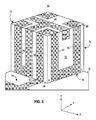
- Figure 3 is a close-up, perspective view of the embodiment of the multi-band antenna 50 depicted in Figure 2 , showing in greater detail how the antenna 50 depicted in Figure 2 is constructed using a three-dimensional rectilinear body as an antenna substrate 52.
- a radiation element 80 of the antenna 50 is a single, elongated strip of metal or other conductive material folded around the faces 64-74 of a cube-shaped antenna substrate 52, except for the bottom face 66, to which the antenna substrate 52 is attached.
- the strip that forms the radiation element 80 has a feed point 82, whereat radio frequency signals for transmission from the antenna 50 are introduced to the antenna 50 from a transmitter and whereat radio signals received by the antenna 50 are recovered from the antenna 50 by a receiver.
- the feed point 82 is located at the edge 84 formed by the intersection of the bottom face 66 and one of the side faces 68.
- the feed point 82 is located away from an edge, e.g., at the interior of the strip connecting the antenna and the ground plane.
- the radiation element 80 has length, width and thickness, the length of which is chosen to be approximately one-quarter the wavelength of a signal in the antenna's fundamental band, e.g., the 800 Mhz band. As will be appreciated from the figures and description below, the length and width will determine the resonant frequencies and characteristic impedances of the antenna 50, however, the width of the strip is also chosen to allow the radiation element 80 to be folded over the faces of the parallelepiped-shaped substrate without having the segments overlap or abut each other.
- a "T"-shaped impedance matching element 88 is located at the terminus end 90 of the strip.
- the input impedance of the antenna 50 at the feed point 82 can thereby be adjusted by varying the length as well as the width of the impedance matching element 88.
- the metal strip or strips forming the impedance matching element 88 are also disposed on one or more faces of the antenna substrate 52. In the embodiment shown, the impedance matching element 88 wraps over the top face 64 and two side faces 70 and 74.
- Segments forming the radiation element 80 and segments forming the impedance matching element 88 can be over coated with a thin layer of insulative material (not shown).
- a non-conductive, i.e., insulative material deposited over the segments can reduce or prevent oxidation of the segments, prevent the segments from being separated from surfaces of the antenna substrate 52 but also prevent the segments from being short circuited during or after installation of the antenna 50 into a mobile device 12.
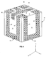
- Figure 4 is another close-up perspective view of the antenna 50 depicted in Figure 3 albeit from a different direction. Figure 4 therefore further illustrates how the metal strip forming the radiation element 80 and the impedance matching section 88 are wrapped around the parallelepiped shaped antenna substrate 52.
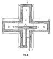
- Figures 5 and 6 are plane views of the antenna depicted in Figure 2 albeit with the faces of the antenna substrate 52 unfolded with the radiation element 80 still on them.
- Figure 5 differs from Figure 6 in that Figure 5 depicts antenna 50 current distributions in the 800 and 900 MHz bands whereas Figure 6 depicts current distributions of the same antenna in the 1800 and 1900 MHz. bands.
- Figures 5 and 6 both show that the radiation element 80 can be considered to be several separate but electrically and physically contiguous elongated planar conductive segments, the segment end points of which being identified in the figures by the letters S, O, and A through L.
- the various segments that comprise the radiation element 80 are therefore denominated as SA, AB, BC, CD, DE, EF, FG, GH, HI, IJ, JK, KL and LO.
- the segments are connected to each other in series and extend between the feed point 82 of the antenna 50 and the impedance matching element 88 at the terminus end 90.
- the sum of the lengths of all the segments SA, AB, BC, CD, DE, EF, FG, GH, HI, IJ, JK, KL, LO, including the length of at least one of segments OM or ON of the impedance matching element 88, are responsible for achieving low frequency band resonances, which for the mobile communications device shown in Figure 1 were 800 and 900 MHz bands.
- a zero current point occurs at the geometric center point P of the antenna 50.
- the geometric center point for the high frequency bands i.e., the 1800, 1900 and 2100 MHz bands will shift however along the EF at various different frequencies of operation.
- the shifting zero current point P makes the current flow along the strips in the Y direction, i.e., strips IH and BC, and current flowing along the strips in the Z direction, i.e., strips DE and GF, HG and CD, JI and AB, KJ and SA, to be in-phase with respect to each other, resulting in high gain, uniform radiation patterns for the cube-shaped antenna 50, as depicted in Figures 7A and 7B .
- segments of the radiation element 80 that are electrically and physically adjacent to each other in the concatenation of elements SA, AB, BC, CD, DE, EF, FG, GH, HI, IJ, JK, KL and LO, are also orthogonal to each other at their points of connection.
- segment SA is connected to segment AB on the top surface 64.
- segment CD which extends over a side face 70 as well as part way over the top surface 64.
- segment CD is orthogonal to segment BC where they meet on the side face 70.
- Segment CD is also orthogonal to segment DE where CD and DE meet on the top surface 64.
- Figures 7A and 7B illustrate graphical representations of measured radiation patterns of the antenna 50 depicted in Figure 2 at both 912 MHz and 1946 MHz.
- the antenna 50 has a radiation pattern in the ZX plane (as marked in Figures 2-4 ) which is a nearly perfect circle at 912 MHz.
- the radiation pattern is also substantially circular at 1946 MHz.
- Figure 7B shows that the antenna 50 has fairly good circular radiation patterns in the YZ plane, (as marked in Figures 2-4 ) at both 912 MHz and at 1946 MHz.
- the radiation pattern emitted from the mobile communication device 12 can therefore be chosen to be at least one of those depicted in Figures 7A and 7B , by simply orienting the antenna substrate 52 within a mobile communications device 12 so that the ZX plane is parallel, orthogonal to or oriented in some other fashion to obtain a desired radiation pattern relative to the earth's surface.
- FIG 8 there is shown a plot of the return-loss of the antenna 50 depicted in Figures 2-4 as a function of frequency.
- the frequency of signal input to the antenna at the feed point 82 is plotted along the abscissa or X-axis 92.
- the ordinate or Y-axis 94 is scaled in terms of return loss in decibels or dB.
- the antenna 50 depicted in Figures 2-4 exhibits a pass band 96 between approximately 800 MHz and 900 MHz.
- a second pass band 98 extends between approximately 1600 MHz and 2200 MHz.
- the antenna will efficiently transduce RF signal energy anywhere within the pass bands 94 and 96.
- the pass bands and their corresponding frequencies therefore define frequency bands wherein a multi-mode communications device can operate efficiently.
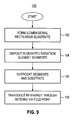
- Figure 9 illustrates a method flow diagram, shown generally at 100, representative of a method of operation of an embodiment of the present invention.
- the method provides for transducing signal energy at a radio device.
- a three-dimensional rectilinear substrate is formed, such as the cube depicted in the figures described above.
- a first radiation element is formed and deposited onto the surface of the substrate.
- the radiation element is formed in the shape of an elongated, thin strip of metal or other conductive material.
- the strip has a predetermined length, which is substantially equal to one-quarter the wavelength of the lowest frequency band at which the antenna will operate. It is important that the antenna strip be provided with a feed point, such as the one described above, whereat signal energy can be introduced to and obtained from the antenna.
- the radiation element can be formed upon the faces of the antenna substrate by different methods. Such methods include but are not limited to, electro-plating, chemical vapor deposition or CVD or by adhesives.
- the segments forming the radiation element and the surfaces of the antenna substrate are overcoated with a thin layer of dielectric material as indicated by step 106, which will protect the segments from oxidation as well as inadvertent short circuiting.
- radio frequency signal energy is then transduced within first, second, third or fourth sets of frequency bands at which the radiation element is resonant.
- the antenna 50 described above defines a strip antenna of small dimensions and which is easily positioned within the housing of a compact mobile station.
- the antenna enables a mobile station to operate on multiple frequency bands, including the quad-bands of a quad-mode mobile station operable at the 800/900/1800/1900 MHz frequency bands, however, the foregoing description should not be construed as limiting because the inventive concept extends to antenna substrates that are not necessarily cube-shaped.
- the antenna substrate 52 in the shape of a cube having the radiation element 80 around its faces a more general description of the antenna 50 is that the antenna is formed from a substrate 52 in the shape of any three-dimensional rectilinear dielectric body.
- a radiation element 80 is disposed on, i.e., wrapped around, multiple sides of the body, with the possible exception of one face on which the substrate is attached to a supporting substrate or mobile unit.
- the antenna substrate 52 and the radiation element 80 are sized together so that it can fit within the small and confined spaces of a multi-band mobile unit 12 yet transduce radio frequency energy in multiple different frequency bands.
- Three-dimensional rectilinear bodies that are usable to form an antenna include but are not limited to, truncated prisms and truncated pyramids, and parallelepipeds generally, e.g., cubes and cuboids, whether such bodies are solid or hollow.
- a truncated prism is considered to be any polyhedron with two polygonal faces lying in parallel planes and with the other faces that connect the two polygonal faces being parallelograms.
- the polygonal faces can include regular polygons such as triangles, squares, rectangles, pentagons, octagons as well as irregular polygons.
- the parallelogram sides can include rectangles and squares. In such a body, the two polygonal faces may or may not correspond to the top face 64 and the bottom face 66 of the cube described above.
- a pyramid is of course a polyhedron having for its base a polygon and faces that are triangles with a common vertex.
- a truncated pyramid is therefore a pyramid with a top portion that is removed to provide a flat top in the shape of a regular polygon.
- the sides of a truncated pyramid are trapezoidal.
- the shape of the bottom face and the shape of the top face will be the same but with the bottom face being larger than the top.
- the slope or inclination of the sides is a design choice and can vary from just over 90 degrees to virtually any angle.
- the antenna disclosed herein significantly reduces the physical size or extension of a multi-band antenna while also increasing the bandwidth of the antenna. Increasing bandwidth is equivalent to reducing the energy stored around the antenna.
- the compact size of the three-dimensional wrapped antenna also lends itself to use in multiple antenna systems, including multiple input and multiple output (MIMO) antenna systems. Because of their size, prior art antennas cannot be used to implement a MIMO antenna system in a portable communications device.
- MIMO multiple input and multiple output
Landscapes
- Support Of Aerials (AREA)
- Variable-Direction Aerials And Aerial Arrays (AREA)
- Waveguide Aerials (AREA)
Abstract
Description
- The present invention relates generally to an antenna construction for a mobile station, or other radio device, operable over multiple frequency bands. More particularly, the present invention relates to antenna apparatus, and an associated methodology for forming a hybrid strip antenna of a multi-mode mobile station, or other radio device, operable, e.g., at the 800/900/1800/1900/2100 MHz frequency bands.
- The antenna includes radiation elements comprising a strip including an impedance matching element disposed upon the external surfaces of a three-dimensional rectilinear substrate, such as a parallelepiped, cube, or pyramidal frustum. The length of the strip is chosen to efficiently transduce RF energy in at least one frequency band of as many as four or more frequency bands. Since a relatively long strip antenna is wound around a very compact substrate, the antenna is of compact dimensions and exhibits stable and relatively wide resonant frequency band characteristics and radiation patterns.
- In modem society, the ready availability and access to mobile radio communication systems through which to communicate is a practical necessity. Cellular, and cellular-like, communication systems are exemplary radio communication systems whose infrastructures have been widely deployed and regularly utilized by many. Successive generations of cellular communication systems have been developed, and their operating parameters and protocols are set forth in standards promulgated by standard-setting bodies. And, successive generations of network apparatus have been deployed, each operable in conformity with an associated operating standard.
- Early-generation cellular communication systems provided voice communication services and limited data communication services. Successor-generation, cellular communication systems provide increasingly data-intensive communication services. Differing operating standards not only provide different communication capabilities, but utilize different communication technologies and differing frequencies of operation in different frequency bands. The installation of different types of cellular communication systems is sometimes geographically dependent. That is to say, in different areas, network infrastructures, operable pursuant to different types of operating standards, are deployed. The network infrastructures deployed in the different areas are not necessarily compatible. A mobile station operable to communicate by way of network infrastructure constructed in conformity with one operating specification is not necessarily operable to communicate by way of network infrastructure operable pursuant to another operating standard.
- So-called, multi-mode mobile stations have been developed that provide the mobile station with communication capability in more than one, i.e., multiple, communication systems, which also operate at different frequencies in different frequency bands. Generally, such multi-mode mobile stations automatically select the manner by which the mobile station is to be operable, responsive to the detected network infrastructure in whose coverage area that the mobile station is positioned. If positioned in the coverage area of the network infrastructures of more than one type of communication system with which the mobile station is capable of communicating, selection of a network infrastructure through which to communicate is made pursuant to a preference scheme, or manually. When provided with multi-mode capability, the mobile station contains circuitry and circuit elements permitting its operation to communicate pursuant to each of the communication systems. Most simply, a multi-mode mobile station is formed of separate circuitry, separately operable to communicate pursuant to the different operating standards. Sometimes, to the extent that circuit elements of the different circuit paths can be shared, parts of the separate circuit paths are constructed to be intertwined, or otherwise shared. By sharing circuit elements, the circuitry size and part count is reduced, resulting in cost and size savings. Sharing of antenna transducer elements between the different circuit paths, however, presents unique challenges. The required size of an antenna transducer element is, in part, dependent upon the frequencies of the signal energy that is to be transduced by the transducer element. And, as mobile station constructions become increasingly miniaturized, housed in housings of increasingly small package sizes, antenna transducer design becomes increasingly difficult, particularly in multi-mode mobile stations when the different modes operate at different frequencies. Significant effort has been exerted to construct an antenna transducer, operable over multiple frequency bands, and also of small dimension to permit its positioning within the housing of a mobile station of compact size.
- A PIFA (Planar Inverted-F Antenna) has been used in multi-mode mobile stations because of its relatively compact size, low profile and because it permits dual-band radiation, however, PIFA antennas have narrow bandwidths. In order to enhance the bandwidth of a PIFA, the structure of the PIFA is sometimes combined together with a parasitic element, or a multi-layered, three-dimensional structure. Such additions, however, increase the volumetric dimensions of the antenna, as well as its weight. The additional resonant branches make the antenna difficult to tune and sometimes introduce EMC and EMI, which interferes with transducing of signal energy. A need therefore exists for an improved small-dimension antenna structure which is also capable of use in multiple different frequency bands.
- It is in light of this background information related to antenna transducers for radio devices that the significant improvements of the present invention have evolved.
-
Figure 1 illustrates a functional block diagram of a radio communication system in which an embodiment of the present invention is operable. -
Figure 2 illustrates a perspective view of an embodiment of the present invention. -
Figure 3 illustrates a close-up perspective view of the embodiment depicted inFigure 2 . -
Figure 4 illustrates another close-up perspective view of the embodiment depicted inFigure 2 but viewed from a different direction than shown inFigure 3 . -
Figure 5 illustrates a plan view of the antenna depicted inFigure 2 with the faces of the substrate unfolded and depicting antenna current flow in the two low or fundamental frequency bands of 800 and 900 MHz. -
Figure 6 illustrates a plan view of the antenna depicted inFigure 2 with the faces of the substrate unfolded as inFigure 5 but instead depicting antenna current flow in the high fundamental frequency bands of 1800 and 1900 MHz. -
Figures 7A and7B illustrate radiation patterns of the antenna shown inFigure 2 in two orthogonal planes, at two different frequencies. -
Figure 8 illustrates a plot of the antenna's return loss as a function of an input signal frequency. -
Figure 9 illustrates a method flow diagram in accordance with an embodiment of the present invention. - Detailed Description
- The present invention, accordingly, advantageously provides compact, lightweight antenna apparatus, and an associated method, for a mobile station, or other radio device, operable over multiple frequency bands.
- Through operation of an embodiment of the present invention, a manner is provided by which to form a hybrid strip antenna of a multi-mode mobile station, or other radio device, operable, e.g., at the 800/900/1800/1900 MHz frequency bands.
- In one aspect of the present invention, an antenna for a multi-mode mobile station is formed of a cube-shaped dielectric antenna substrate, the surfaces of which carry an end-fed antenna strip, formed of a strip of metal or other conductive material having a length, width and thickness. The length of the strip is much longer than the dimensions of any one face of the antenna substrate, requiring the strip to be folded at least part way over different faces of the antenna substrate. In other words, the length of the antenna strip is multiples of the dimensions of any one face of the cube. The antenna includes a feed point at one end of the strip and a "T"-shaped impedance matching/adjustment element at the end of the strip opposite the feed point.
- The cube dimensions and the length and width of the radiation element, which of course also receives signals, are selected so that the radiation element can be "folded" across or "wrapped" around several faces of the cube without the radiation element overlapping itself and without the edges of the radiation element abutting each other. The cube dimensions are also selected so that the cube can fit within the housing of a mobile station.
- In the embodiment depicted in the figures, the length of the strip forming the antenna element was approximately one-quarter the wavelength of a signal in the 800 MHz frequency band, and it effectuated resonance in both the 800 and 900 MHz bands. The antenna was also resonant in the 1800, 1900 and 2100 MHz bands.
- Since the length of the metal strip forming the radiator is such that the radiator is wrapped around different faces of the cube, the strip forming the radiation element can be thought of, and also described as, several different substantially equallength conductive segments that are electrically connected to each other in series. Successive segments are joined to each other on the cube face such that each segment's length dimension is orthogonal to the length dimension of adjacent segments. In the embodiments shown, each cube face supports more than one antenna segment. The impedance matching element at the terminus end of the strip is also folded across cube faces.
- Due to the compact size, stability of operation, and stable radiation pattern provided by the antenna, the antenna is advantageously utilized in a mobile station, or other radio device, of small volumetric dimensions.
- In these and other aspects, therefore, a folded strip antenna, and an associated methodology is provided for a multi-band communication device. The folded strip antenna is embodied by forming a dielectric material into the shape of a cube. A radiation element, such as a thin, flat metal strip, has a length and width such that the strip can be folded to extend at least part way across several of the different faces of the cube.
- Turning, therefore, first to
Figure 1 , a radio communication system, shown generally at 10, provides for radio communications with mobile stations, of which themobile station 12 is representative. Themobile station 12 is here representative of a quad-mode mobile station, capable of communicating at the 800/900/1800/1900 MHz frequency bands. Such a mobile station is sometimes referred to as a world-band mobile station as the mobile station is operable in conformity with the operating specifications and protocols of the cellular communication systems that presently are predominant. More generally, the mobile station is representative of various radio devices that are operable over multiple bands or large bandwidths at relatively high frequencies. -
Radio access networks mobile station 12 is positioned within the coverage area of any of the radio access networks 14-22, the mobile station is capable of communicating therewith. If the separate networks have overlapping coverage areas, then the selection is made as to which of the networks through which to communicate. The radio access networks 14-22 are coupled, here by way of gateways (GWYs) 26 to acore network 28. A communication endpoint (CE) 32 that is representative of a communication device that communicates with the mobile station. - The
mobile station 12 includes a radio transceiver havingtransceiver circuitry 36 capable of transceiving communication signals with any of the networks 14-22. The transceiver circuitry includes separate or shared transceiver paths constructed to be operable with the operating standards and protocols of the respective networks. The radio station further includes anantenna 50 of an embodiment of the present invention. The antenna is of characteristics to be operable at the different frequency bands at which the transceiver circuitry and the radio access networks are operable. Here, theantenna 50 is operable at the 800, 900, 1800, and 1900 MHz frequency bands. In the exemplary implementation, theantenna 50 is housed together with the transceiver circuitry, in ahousing 44 of the mobile station. As the space within the housing that is available to house the antenna is limited, the dimensions of theantenna 50 are correspondingly small while providing for the transducing of signal energy by the antenna over broad frequencies at which the mobile station is operable. -
Figure 2 illustrates an exemplary implementation of amulti-band strip antenna 50 for themulti-band communications device 12, depicted inFigure 1 . Themulti-band strip antenna 50 is comprised of adielectric antenna substrate 52 having the shape of right rectangular parallelepiped but which is also accurately described as a type of three-dimensional rectilinear body. The parallelepiped-shapedantenna substrate 52 shown inFigure 2 is more commonly known as a cube, which of course has six rectangular, i.e., square, sides, denominated here as atop face 64,bottom face 66 and four side faces 68, 70, 72 and 74 that extend between corresponding edges of thetop face 64 andbottom face 66. - Inasmuch as the
antenna substrate 52 is in the shape of a cube, thetop face 64 andbottom face 66 are planar or at least substantially planar and lie in corresponding parallel but spaced-apart geometric planes, the separation distance of which defines the height, H, of the cube. The side faces 68, 70, 72 and 74 of theantenna substrate 52 are also planar or substantially planar and orthogonal to thetop face 64 and thebottom face 66 with faces adjacent to each other also being orthogonal to each other. - In
Figure 2 , theantenna 50 is depicted atop a substantially planardielectric supporting substrate 76 to which ametal ground plane 78 is also attached. When theantenna 50 and supportingsubstrate 76 with theground plane 78 as shown inFigure 2 are used in amobile communications device 12, theground plane 78 acts to shield circuitry of thedevice 12 from signals emitted from the antenna as well as electromagnetic interference or EMI from external sources. Theground plane 78 also shapes the radiation pattern of theantenna 50. - In one embodiment, a three-dimensional
rectilinear antenna substrate 52 depicted is fabricated as a solid piece of molded dielectric material, in which case, the substrate will of course have multiple sides. A cube-shapedsubstrate 52 will have six sides. In embodiments where theantenna substrate 52 is solid, thebottom face 66 of thesubstrate 52 will abut a surface of the supportingsubstrate 76 when theantenna substrate 52 is mounted atop a supportingsubstrate 76. Since asolid substrate 52 will add weight and cost, in at least one other embodiment, the three-dimensionalrectilinear antenna substrate 52 is not solid but is instead constructed from one or more separate panels of dielectric material that is folded into a desired shape for theantenna substrate 52. In yet another embodiment, the parallelepiped is constructed from several separate discrete panels affixed to each other. Various well-known methods of attachment can be used including, but not limited to, adhesives, heat, ultrasonic welding or mechanical fasteners. - In embodiments where the
antenna substrate 52 is not solid but is instead composed of multiple panels and therefore hollow, a cube-shapedantenna substrate 52 can have either five or six sides, the construction of which is referred to herein as being a panelized substrate. In embodiments wherein apanelized antenna substrate 52, such as a cube-shaped substrate is constructed to have only five sides and which is then mounted to a separate supportingsubstrate 76, the portion of the supportingsubstrate 76 that is directly below thehollow antenna substrate 52 is then considered to be a de facto "side" of theantenna substrate 52. The portion of the supportingsubstrate 76 directly below theantenna substrate 52 is considered herein to be the "bottom"face 66 of theparallelepiped antenna substrate 52. -
Figure 3 is a close-up, perspective view of the embodiment of themulti-band antenna 50 depicted inFigure 2 , showing in greater detail how theantenna 50 depicted inFigure 2 is constructed using a three-dimensional rectilinear body as anantenna substrate 52. - As can be seen in
Figure 3 , aradiation element 80 of theantenna 50 is a single, elongated strip of metal or other conductive material folded around the faces 64-74 of a cube-shapedantenna substrate 52, except for thebottom face 66, to which theantenna substrate 52 is attached. As with any end-fed strip antenna, the strip that forms theradiation element 80 has afeed point 82, whereat radio frequency signals for transmission from theantenna 50 are introduced to theantenna 50 from a transmitter and whereat radio signals received by theantenna 50 are recovered from theantenna 50 by a receiver. In the embodiment shown inFigure 3 , thefeed point 82 is located at theedge 84 formed by the intersection of thebottom face 66 and one of the side faces 68. In alternate embodiments of theantenna 50, thefeed point 82 is located away from an edge, e.g., at the interior of the strip connecting the antenna and the ground plane. - The
radiation element 80 has length, width and thickness, the length of which is chosen to be approximately one-quarter the wavelength of a signal in the antenna's fundamental band, e.g., the 800 Mhz band. As will be appreciated from the figures and description below, the length and width will determine the resonant frequencies and characteristic impedances of theantenna 50, however, the width of the strip is also chosen to allow theradiation element 80 to be folded over the faces of the parallelepiped-shaped substrate without having the segments overlap or abut each other. - Note that a "T"-shaped
impedance matching element 88 is located at theterminus end 90 of the strip. The input impedance of theantenna 50 at thefeed point 82 can thereby be adjusted by varying the length as well as the width of theimpedance matching element 88. As with the metal strip that forms theradiation element 80, the metal strip or strips forming theimpedance matching element 88 are also disposed on one or more faces of theantenna substrate 52. In the embodiment shown, theimpedance matching element 88 wraps over thetop face 64 and two side faces 70 and 74. - Segments forming the
radiation element 80 and segments forming theimpedance matching element 88 can be over coated with a thin layer of insulative material (not shown). A non-conductive, i.e., insulative material deposited over the segments can reduce or prevent oxidation of the segments, prevent the segments from being separated from surfaces of theantenna substrate 52 but also prevent the segments from being short circuited during or after installation of theantenna 50 into amobile device 12. -
Figure 4 is another close-up perspective view of theantenna 50 depicted inFigure 3 albeit from a different direction.Figure 4 therefore further illustrates how the metal strip forming theradiation element 80 and theimpedance matching section 88 are wrapped around the parallelepiped shapedantenna substrate 52. - An even better understanding of the construction and operation of the
antenna 50 can be had fromFigures 5 and6 , which are plane views of the antenna depicted inFigure 2 albeit with the faces of theantenna substrate 52 unfolded with theradiation element 80 still on them.Figure 5 differs fromFigure 6 in thatFigure 5 depictsantenna 50 current distributions in the 800 and 900 MHz bands whereasFigure 6 depicts current distributions of the same antenna in the 1800 and 1900 MHz. bands. -
Figures 5 and6 both show that theradiation element 80 can be considered to be several separate but electrically and physically contiguous elongated planar conductive segments, the segment end points of which being identified in the figures by the letters S, O, and A through L. The various segments that comprise theradiation element 80 are therefore denominated as SA, AB, BC, CD, DE, EF, FG, GH, HI, IJ, JK, KL and LO. The segments are connected to each other in series and extend between thefeed point 82 of theantenna 50 and theimpedance matching element 88 at theterminus end 90. The sum of the lengths of all the segments SA, AB, BC, CD, DE, EF, FG, GH, HI, IJ, JK, KL, LO, including the length of at least one of segments OM or ON of theimpedance matching element 88, are responsible for achieving low frequency band resonances, which for the mobile communications device shown inFigure 1 were 800 and 900 MHz bands. - Because of the symmetry of the layout of the segments on the
antenna substrate 52, a zero current point occurs at the geometric center point P of theantenna 50. The geometric center point for the high frequency bands i.e., the 1800, 1900 and 2100 MHz bands will shift however along the EF at various different frequencies of operation. The shifting zero current point P makes the current flow along the strips in the Y direction, i.e., strips IH and BC, and current flowing along the strips in the Z direction, i.e., strips DE and GF, HG and CD, JI and AB, KJ and SA, to be in-phase with respect to each other, resulting in high gain, uniform radiation patterns for the cube-shapedantenna 50, as depicted inFigures 7A and7B . - Note that for every two segments that are electrically connected to each other, such as the segments AB and BC, or BC and CD, or DE and EF, one of them extends at least part way across two adjacent faces of the substrate so that one of the segments folds over an edge of the cube to allow the metal strip forming the radiation element to change direction and extend onto an adjacent face. Stated another way, segments of the
radiation element 80 that are electrically and physically adjacent to each other in the concatenation of elements SA, AB, BC, CD, DE, EF, FG, GH, HI, IJ, JK, KL and LO, are also orthogonal to each other at their points of connection. - By way of example, segment SA is connected to segment AB on the
top surface 64. As can be seen inFigures 3 and4 , the portions of segments SA and AB on the side faces 68 and 70 are parallel, however, SA and AB are orthogonal to each other where they meet, i.e., on thetop surface 64. Consider also segment CD, which extends over aside face 70 as well as part way over thetop surface 64. While segment CD is orthogonal to segment BC where they meet on theside face 70. Segment CD is also orthogonal to segment DE where CD and DE meet on thetop surface 64. Thus two successive segments SA, AB, BC, CD, DE, EF, FG, GH, HI, IJ, JK, KL and LO, are orthogonal to each other where they meet on the surfaces of theantenna substrate 52. -
Figures 7A and7B illustrate graphical representations of measured radiation patterns of theantenna 50 depicted inFigure 2 at both 912 MHz and 1946 MHz. As can be seen inFigure 7A , theantenna 50 has a radiation pattern in the ZX plane (as marked inFigures 2-4 ) which is a nearly perfect circle at 912 MHz. The radiation pattern is also substantially circular at 1946 MHz.Figure 7B shows that theantenna 50 has fairly good circular radiation patterns in the YZ plane, (as marked inFigures 2-4 ) at both 912 MHz and at 1946 MHz. The radiation pattern emitted from themobile communication device 12 can therefore be chosen to be at least one of those depicted inFigures 7A and7B , by simply orienting theantenna substrate 52 within amobile communications device 12 so that the ZX plane is parallel, orthogonal to or oriented in some other fashion to obtain a desired radiation pattern relative to the earth's surface. - Referring now to
Figure 8 there is shown a plot of the return-loss of theantenna 50 depicted inFigures 2-4 as a function of frequency. The frequency of signal input to the antenna at thefeed point 82 is plotted along the abscissa orX-axis 92. The ordinate or Y-axis 94 is scaled in terms of return loss in decibels or dB. - The
antenna 50 depicted inFigures 2-4 exhibits apass band 96 between approximately 800 MHz and 900 MHz. Asecond pass band 98 extends between approximately 1600 MHz and 2200 MHz. As shown by theFigure 8 , the antenna will efficiently transduce RF signal energy anywhere within thepass bands -
Figure 9 illustrates a method flow diagram, shown generally at 100, representative of a method of operation of an embodiment of the present invention. The method provides for transducing signal energy at a radio device. - First, and as indicated by the
block 102, a three-dimensional rectilinear substrate is formed, such as the cube depicted in the figures described above. As indicated inblock 104, a first radiation element is formed and deposited onto the surface of the substrate. - The radiation element is formed in the shape of an elongated, thin strip of metal or other conductive material. The strip has a predetermined length, which is substantially equal to one-quarter the wavelength of the lowest frequency band at which the antenna will operate. It is important that the antenna strip be provided with a feed point, such as the one described above, whereat signal energy can be introduced to and obtained from the antenna.
- The radiation element can be formed upon the faces of the antenna substrate by different methods. Such methods include but are not limited to, electro-plating, chemical vapor deposition or CVD or by adhesives. In one embodiment, the segments forming the radiation element and the surfaces of the antenna substrate are overcoated with a thin layer of dielectric material as indicated by
step 106, which will protect the segments from oxidation as well as inadvertent short circuiting. - As shown in
block 108, radio frequency signal energy is then transduced within first, second, third or fourth sets of frequency bands at which the radiation element is resonant. - The
antenna 50 described above defines a strip antenna of small dimensions and which is easily positioned within the housing of a compact mobile station. The antenna enables a mobile station to operate on multiple frequency bands, including the quad-bands of a quad-mode mobile station operable at the 800/900/1800/1900 MHz frequency bands, however, the foregoing description should not be construed as limiting because the inventive concept extends to antenna substrates that are not necessarily cube-shaped. - While the embodiment depicted in the figures and described above used an antenna substrate in the shape of a cube having the
radiation element 80 around its faces, a more general description of theantenna 50 is that the antenna is formed from asubstrate 52 in the shape of any three-dimensional rectilinear dielectric body. Aradiation element 80 is disposed on, i.e., wrapped around, multiple sides of the body, with the possible exception of one face on which the substrate is attached to a supporting substrate or mobile unit. Theantenna substrate 52 and theradiation element 80 are sized together so that it can fit within the small and confined spaces of a multi-bandmobile unit 12 yet transduce radio frequency energy in multiple different frequency bands. - Three-dimensional rectilinear bodies that are usable to form an antenna include but are not limited to, truncated prisms and truncated pyramids, and parallelepipeds generally, e.g., cubes and cuboids, whether such bodies are solid or hollow. As used herein, a truncated prism is considered to be any polyhedron with two polygonal faces lying in parallel planes and with the other faces that connect the two polygonal faces being parallelograms. The polygonal faces can include regular polygons such as triangles, squares, rectangles, pentagons, octagons as well as irregular polygons. The parallelogram sides can include rectangles and squares. In such a body, the two polygonal faces may or may not correspond to the
top face 64 and thebottom face 66 of the cube described above. - A pyramid is of course a polyhedron having for its base a polygon and faces that are triangles with a common vertex. A truncated pyramid is therefore a pyramid with a top portion that is removed to provide a flat top in the shape of a regular polygon. The sides of a truncated pyramid are trapezoidal. In a truncated pyramid, the shape of the bottom face and the shape of the top face will be the same but with the bottom face being larger than the top. The slope or inclination of the sides is a design choice and can vary from just over 90 degrees to virtually any angle.
- It will be recognized by those of ordinary skill in the art that as the shape of the
antenna substrate 52 varies from a cube, the spatial relationships between antenna segments on differently arranged faces will also vary. As the spatial relationship between the segment vary, the pattern of RF signal energy is radiated from them will also vary. It is therefore expected that an emitted radiation pattern for an antenna formed from a substrate other than the cube depicted inFigures 2-4 will likely vary from the radiation patterns depicted inFigures 7A and7B . The true scope of the invention is defined by the appurtenant claims. - By using three-dimensional wrapping, the antenna disclosed herein significantly reduces the physical size or extension of a multi-band antenna while also increasing the bandwidth of the antenna. Increasing bandwidth is equivalent to reducing the energy stored around the antenna.
- The compact size of the three-dimensional wrapped antenna also lends itself to use in multiple antenna systems, including multiple input and multiple output (MIMO) antenna systems. Because of their size, prior art antennas cannot be used to implement a MIMO antenna system in a portable communications device.
- Presently preferred embodiments of the invention and many of its improvements and advantages have been described with a degree of particularity.
The description is of preferred examples of implementing the invention, and the description of preferred examples is not necessarily intended to limit the scope of the invention. The scope of the invention is defined by the following claims.
Claims (20)
- A multi-band strip antenna for a communication device, the antenna comprising:a three-dimensional rectilinear antenna substrate having a plurality of faces; anda radiation element formed of a plurality of N, elongated planar conductive segments, each of which is disposed upon at least one face of the three-dimensional rectilinear antenna substrate such that the segments are electrically connected to each other in series, the combined lengths of the segments being selected to be substantially equal to a one-quarter wavelength a lowest frequency band of two different frequency bands in which the strip antenna is capable of operating.
- The strip antenna of claim 1, further comprising a T-shaped impedance matching element coupled with a terminus end of the radiation element, said T-shaped impedance matching element disposed on at least one surface of the antenna substrate.
- The strip antenna of claim 2, further comprising an insulative layer deposited over at least one of: the radiation element and the T-shaped an impedance matching element.
- The strip antenna of claim 1, wherein at least two faces of the three-dimensional rectilinear antenna substrate are substantially rectangular.
- The strip antenna of claim 1, wherein at least two faces of the three-dimensional rectilinear antenna substrate are parallelograms.
- The strip antenna of claim 1, wherein the three-dimensional rectilinear antenna substrate is in the shape of a cube.
- The strip antenna of claim 1, wherein the three-dimensional rectilinear antenna substrate is in the shape of truncated pyramid.
- The strip antenna of claim 1, wherein the radiation element is sized, shaped and arranged to transduce signal energy in a plurality of different frequency bands.
- The strip antenna of claim 8, wherein the plurality of different bands include at least two of: the 800 Mhz band; the 900 Mhz band; the 1800 Mhz band; and the 1900 Mhz band.
- The strip antenna of claim 8, wherein the plurality of different bands include at least: the 800 Mhz band; the 900 Mhz band; the 1800 Mhz band; and the 1900 Mhz band.
- The strip antenna of claim 9, wherein the pattern of radiation emitted from the antenna in the 900 MHz band is substantially circular, in at least one direction.
- A multi-band strip antenna for a communication device, said strip antenna comprising:a dielectric antenna substrate in the shape of a cube having a plurality of faces;a radiation element formed of a plurality of N, elongated planar and conductive segments of conductive material disposed on surfaces of the cube such that they are connected to each other in series, the series-connected segments defining a feed point for the antenna and a terminus end that is opposite the feed point; andan impedance matching element comprised of a length of conductive material electrically coupled with the radiation element, each segment of the plurality of segments extending at least part way across a face of the substrate, the radiation element having a physical length equal to the combined length of the N segments such that the radiation element is folded over and disposed on a plurality of the faces of the substrate.
- The strip antenna of claim 12, wherein the combined lengths of the N segments is substantially equal to a quarter wavelength of a first operating band of the antenna.
- A method of transducing radio frequency energy from a multi-band communication device comprising the steps of:forming a three-dimensional rectilinear substrate, said substrate having a plurality of external surfaces; anddepositing an elongated, thin strip of conductive material, having a predetermined length, onto a plurality of the external surfaces of the three-dimensional rectilinear substrate, the strip of conductive material defining a feed point for the antenna.
- The method of claim 14 further including the step of: transducing radio frequency signal energy at the feed point, the radio frequency energy being in at least one of four different frequency bands at which the radiation element is resonant.
- The method of claim 14, wherein the step of forming includes the step of forming a cube.
- The method of claim 14 further comprising a step of over coating at least a portion of the conductive material.
- The method of claim 14, wherein the step of depositing includes the step of depositing a strip having a length substantially equal to one-quarter the wavelength of a lowest frequency band at which the antenna will operate.
- The method of claim 14 wherein the step of depositing includes at least one of: electro-plating; chemical vapor deposition; and adhesion.
- The method of claim 14 further including the step of transducing radio frequency energy within at least one of at least first and second frequency bands at which the radiation element is resonant.
Priority Applications (2)
| Application Number | Priority Date | Filing Date | Title |
|---|---|---|---|
| AT07114887T ATE534164T1 (en) | 2007-08-23 | 2007-08-23 | MULTI-BAND ANTENNA ARRANGEMENT ARRANGE ON A THREE-DIMENSIONAL SUBSTRATE |
| EP07114887A EP2028717B1 (en) | 2007-08-23 | 2007-08-23 | Multi-band antenna apparatus disposed on a three-dimensional substrate |
Applications Claiming Priority (1)
| Application Number | Priority Date | Filing Date | Title |
|---|---|---|---|
| EP07114887A EP2028717B1 (en) | 2007-08-23 | 2007-08-23 | Multi-band antenna apparatus disposed on a three-dimensional substrate |
Publications (2)
| Publication Number | Publication Date |
|---|---|
| EP2028717A1 true EP2028717A1 (en) | 2009-02-25 |
| EP2028717B1 EP2028717B1 (en) | 2011-11-16 |
Family
ID=38511372
Family Applications (1)
| Application Number | Title | Priority Date | Filing Date |
|---|---|---|---|
| EP07114887A Active EP2028717B1 (en) | 2007-08-23 | 2007-08-23 | Multi-band antenna apparatus disposed on a three-dimensional substrate |
Country Status (2)
| Country | Link |
|---|---|
| EP (1) | EP2028717B1 (en) |
| AT (1) | ATE534164T1 (en) |
Cited By (5)
| Publication number | Priority date | Publication date | Assignee | Title |
|---|---|---|---|---|
| CN105244597A (en) * | 2015-09-16 | 2016-01-13 | 南京信息工程大学 | Tri-band mobile phone antenna |
| CN105406187A (en) * | 2015-12-16 | 2016-03-16 | 南京信息工程大学 | Dual-band three-dimensional inverted F antenna |
| WO2022006986A1 (en) * | 2020-07-10 | 2022-01-13 | 瑞声声学科技(深圳)有限公司 | Laminated antenna and terminal device |
| WO2024169336A1 (en) * | 2023-02-17 | 2024-08-22 | 华为技术有限公司 | Feed network and antenna device |
| WO2025179492A1 (en) * | 2024-02-28 | 2025-09-04 | 京东方科技集团股份有限公司 | Antenna unit and antenna device |
Citations (7)
| Publication number | Priority date | Publication date | Assignee | Title |
|---|---|---|---|---|
| EP1195845A2 (en) | 2000-10-09 | 2002-04-10 | Philips Corporate Intellectual Property GmbH | Miniaturised microwave antenna |
| EP1198027A1 (en) | 2000-10-12 | 2002-04-17 | The Furukawa Electric Co., Ltd. | Small antenna |
| US20020145569A1 (en) * | 2001-04-10 | 2002-10-10 | Murata Manufacturing Co., Ltd. | Antenna apparatus |
| EP1414108A2 (en) | 2002-10-23 | 2004-04-28 | Murata Manufacturing Co., Ltd. | Surface mount antenna, antenna device and communication device using the same |
| US20040125032A1 (en) | 2002-12-13 | 2004-07-01 | Kyocera Corporation | Surface-mount type antenna and antenna apparatus |
| US20050156790A1 (en) | 2002-04-12 | 2005-07-21 | Sony Corporation | Broadband antenna apparatus |
| WO2006073034A1 (en) * | 2005-01-05 | 2006-07-13 | Murata Manufacturing Co., Ltd. | Antenna structure and wireless communication unit having the same |
-
2007
- 2007-08-23 EP EP07114887A patent/EP2028717B1/en active Active
- 2007-08-23 AT AT07114887T patent/ATE534164T1/en active
Patent Citations (7)
| Publication number | Priority date | Publication date | Assignee | Title |
|---|---|---|---|---|
| EP1195845A2 (en) | 2000-10-09 | 2002-04-10 | Philips Corporate Intellectual Property GmbH | Miniaturised microwave antenna |
| EP1198027A1 (en) | 2000-10-12 | 2002-04-17 | The Furukawa Electric Co., Ltd. | Small antenna |
| US20020145569A1 (en) * | 2001-04-10 | 2002-10-10 | Murata Manufacturing Co., Ltd. | Antenna apparatus |
| US20050156790A1 (en) | 2002-04-12 | 2005-07-21 | Sony Corporation | Broadband antenna apparatus |
| EP1414108A2 (en) | 2002-10-23 | 2004-04-28 | Murata Manufacturing Co., Ltd. | Surface mount antenna, antenna device and communication device using the same |
| US20040125032A1 (en) | 2002-12-13 | 2004-07-01 | Kyocera Corporation | Surface-mount type antenna and antenna apparatus |
| WO2006073034A1 (en) * | 2005-01-05 | 2006-07-13 | Murata Manufacturing Co., Ltd. | Antenna structure and wireless communication unit having the same |
Cited By (6)
| Publication number | Priority date | Publication date | Assignee | Title |
|---|---|---|---|---|
| CN105244597A (en) * | 2015-09-16 | 2016-01-13 | 南京信息工程大学 | Tri-band mobile phone antenna |
| CN105406187A (en) * | 2015-12-16 | 2016-03-16 | 南京信息工程大学 | Dual-band three-dimensional inverted F antenna |
| CN105406187B (en) * | 2015-12-16 | 2018-09-25 | 南京信息工程大学 | A kind of two-band solid inverse-F antenna |
| WO2022006986A1 (en) * | 2020-07-10 | 2022-01-13 | 瑞声声学科技(深圳)有限公司 | Laminated antenna and terminal device |
| WO2024169336A1 (en) * | 2023-02-17 | 2024-08-22 | 华为技术有限公司 | Feed network and antenna device |
| WO2025179492A1 (en) * | 2024-02-28 | 2025-09-04 | 京东方科技集团股份有限公司 | Antenna unit and antenna device |
Also Published As
| Publication number | Publication date |
|---|---|
| ATE534164T1 (en) | 2011-12-15 |
| EP2028717B1 (en) | 2011-11-16 |
Similar Documents
| Publication | Publication Date | Title |
|---|---|---|
| US7714795B2 (en) | Multi-band antenna apparatus disposed on a three-dimensional substrate, and associated methodology, for a radio device | |
| CN102414914B (en) | Balanced metamaterial antenna device | |
| US6459413B1 (en) | Multi-frequency band antenna | |
| US7642970B2 (en) | Antenna device and wireless communication apparatus using same | |
| US6424300B1 (en) | Notch antennas and wireless communicators incorporating same | |
| US7148851B2 (en) | Antenna device and communications apparatus comprising same | |
| US7057558B2 (en) | Antenna device | |
| US6873291B2 (en) | Surface-mounted antenna and communications apparatus comprising same | |
| US7812772B2 (en) | Antenna, and associated method, for a multi-band radio device | |
| EP1845582B1 (en) | Wide-band antenna device comprising a U-shaped conductor antenna | |
| TWI404265B (en) | Printed dipole antenna and its manufacturing method | |
| US20080231531A1 (en) | Antenna apparatus, and associated methodology, for a multi-band radio device | |
| KR101188465B1 (en) | Antenna apparatus, and associated methodology, for a multi-band radio device | |
| WO2008148569A2 (en) | Dual-polarized radiating element, dual-band dual-polarized antenna assembly and dual-polarized antenna array | |
| US7629933B2 (en) | Multi-band antenna, and associated methodology, for a radio communication device | |
| US20030103008A1 (en) | In-building low profile antenna | |
| EP2028717A1 (en) | Multi-band antenna apparatus disposed on a three-dimensional substrate | |
| CN109167160B (en) | Antenna Units and GNSS Survey Antennas | |
| CN112510354A (en) | Antenna and electronic equipment | |
| CN115173038A (en) | Miniaturized dual-frequency quadrifilar helix antenna | |
| JPH07288423A (en) | Mobile radio antenna | |
| EP1372213A1 (en) | Multi-frequency band antenna | |
| EP4456322A1 (en) | Antenna module and electronic device comprising same | |
| JP2007524322A (en) | Antenna array | |
| EP2028718A1 (en) | Multi-band antenna, and associated methodology, for a radio communication device |
Legal Events
| Date | Code | Title | Description |
|---|---|---|---|
| PUAI | Public reference made under article 153(3) epc to a published international application that has entered the european phase |
Free format text: ORIGINAL CODE: 0009012 |
|
| 17P | Request for examination filed |
Effective date: 20070824 |
|
| AK | Designated contracting states |
Kind code of ref document: A1 Designated state(s): AT BE BG CH CY CZ DE DK EE ES FI FR GB GR HU IE IS IT LI LT LU LV MC MT NL PL PT RO SE SI SK TR |
|
| AX | Request for extension of the european patent |
Extension state: AL BA HR MK RS |
|
| AKX | Designation fees paid |
Designated state(s): AT BE BG CH CY CZ DE DK EE ES FI FR GB GR HU IE IS IT LI LT LU LV MC MT NL PL PT RO SE SI SK TR |
|
| GRAP | Despatch of communication of intention to grant a patent |
Free format text: ORIGINAL CODE: EPIDOSNIGR1 |
|
| GRAS | Grant fee paid |
Free format text: ORIGINAL CODE: EPIDOSNIGR3 |
|
| GRAA | (expected) grant |
Free format text: ORIGINAL CODE: 0009210 |
|
| AK | Designated contracting states |
Kind code of ref document: B1 Designated state(s): AT BE BG CH CY CZ DE DK EE ES FI FR GB GR HU IE IS IT LI LT LU LV MC MT NL PL PT RO SE SI SK TR |
|
| REG | Reference to a national code |
Ref country code: GB Ref legal event code: FG4D |
|
| REG | Reference to a national code |
Ref country code: CH Ref legal event code: EP |
|
| REG | Reference to a national code |
Ref country code: IE Ref legal event code: FG4D |
|
| REG | Reference to a national code |
Ref country code: DE Ref legal event code: R096 Ref document number: 602007018722 Country of ref document: DE Effective date: 20120119 |
|
| REG | Reference to a national code |
Ref country code: NL Ref legal event code: VDEP Effective date: 20111116 |
|
| REG | Reference to a national code |
Ref country code: SE Ref legal event code: TRGR |
|
| LTIE | Lt: invalidation of european patent or patent extension |
Effective date: 20111116 |
|
| PG25 | Lapsed in a contracting state [announced via postgrant information from national office to epo] |
Ref country code: IS Free format text: LAPSE BECAUSE OF FAILURE TO SUBMIT A TRANSLATION OF THE DESCRIPTION OR TO PAY THE FEE WITHIN THE PRESCRIBED TIME-LIMIT Effective date: 20120316 Ref country code: LT Free format text: LAPSE BECAUSE OF FAILURE TO SUBMIT A TRANSLATION OF THE DESCRIPTION OR TO PAY THE FEE WITHIN THE PRESCRIBED TIME-LIMIT Effective date: 20111116 |
|
| PG25 | Lapsed in a contracting state [announced via postgrant information from national office to epo] |
Ref country code: SI Free format text: LAPSE BECAUSE OF FAILURE TO SUBMIT A TRANSLATION OF THE DESCRIPTION OR TO PAY THE FEE WITHIN THE PRESCRIBED TIME-LIMIT Effective date: 20111116 Ref country code: BE Free format text: LAPSE BECAUSE OF FAILURE TO SUBMIT A TRANSLATION OF THE DESCRIPTION OR TO PAY THE FEE WITHIN THE PRESCRIBED TIME-LIMIT Effective date: 20111116 Ref country code: NL Free format text: LAPSE BECAUSE OF FAILURE TO SUBMIT A TRANSLATION OF THE DESCRIPTION OR TO PAY THE FEE WITHIN THE PRESCRIBED TIME-LIMIT Effective date: 20111116 Ref country code: PT Free format text: LAPSE BECAUSE OF FAILURE TO SUBMIT A TRANSLATION OF THE DESCRIPTION OR TO PAY THE FEE WITHIN THE PRESCRIBED TIME-LIMIT Effective date: 20120316 Ref country code: GR Free format text: LAPSE BECAUSE OF FAILURE TO SUBMIT A TRANSLATION OF THE DESCRIPTION OR TO PAY THE FEE WITHIN THE PRESCRIBED TIME-LIMIT Effective date: 20120217 Ref country code: PL Free format text: LAPSE BECAUSE OF FAILURE TO SUBMIT A TRANSLATION OF THE DESCRIPTION OR TO PAY THE FEE WITHIN THE PRESCRIBED TIME-LIMIT Effective date: 20111116 Ref country code: LV Free format text: LAPSE BECAUSE OF FAILURE TO SUBMIT A TRANSLATION OF THE DESCRIPTION OR TO PAY THE FEE WITHIN THE PRESCRIBED TIME-LIMIT Effective date: 20111116 |
|
| PG25 | Lapsed in a contracting state [announced via postgrant information from national office to epo] |
Ref country code: CY Free format text: LAPSE BECAUSE OF FAILURE TO SUBMIT A TRANSLATION OF THE DESCRIPTION OR TO PAY THE FEE WITHIN THE PRESCRIBED TIME-LIMIT Effective date: 20111116 |
|
| PG25 | Lapsed in a contracting state [announced via postgrant information from national office to epo] |
Ref country code: CZ Free format text: LAPSE BECAUSE OF FAILURE TO SUBMIT A TRANSLATION OF THE DESCRIPTION OR TO PAY THE FEE WITHIN THE PRESCRIBED TIME-LIMIT Effective date: 20111116 Ref country code: EE Free format text: LAPSE BECAUSE OF FAILURE TO SUBMIT A TRANSLATION OF THE DESCRIPTION OR TO PAY THE FEE WITHIN THE PRESCRIBED TIME-LIMIT Effective date: 20111116 Ref country code: SK Free format text: LAPSE BECAUSE OF FAILURE TO SUBMIT A TRANSLATION OF THE DESCRIPTION OR TO PAY THE FEE WITHIN THE PRESCRIBED TIME-LIMIT Effective date: 20111116 Ref country code: BG Free format text: LAPSE BECAUSE OF FAILURE TO SUBMIT A TRANSLATION OF THE DESCRIPTION OR TO PAY THE FEE WITHIN THE PRESCRIBED TIME-LIMIT Effective date: 20120216 Ref country code: DK Free format text: LAPSE BECAUSE OF FAILURE TO SUBMIT A TRANSLATION OF THE DESCRIPTION OR TO PAY THE FEE WITHIN THE PRESCRIBED TIME-LIMIT Effective date: 20111116 |
|
| PG25 | Lapsed in a contracting state [announced via postgrant information from national office to epo] |
Ref country code: IT Free format text: LAPSE BECAUSE OF FAILURE TO SUBMIT A TRANSLATION OF THE DESCRIPTION OR TO PAY THE FEE WITHIN THE PRESCRIBED TIME-LIMIT Effective date: 20111116 Ref country code: RO Free format text: LAPSE BECAUSE OF FAILURE TO SUBMIT A TRANSLATION OF THE DESCRIPTION OR TO PAY THE FEE WITHIN THE PRESCRIBED TIME-LIMIT Effective date: 20111116 |
|
| REG | Reference to a national code |
Ref country code: AT Ref legal event code: MK05 Ref document number: 534164 Country of ref document: AT Kind code of ref document: T Effective date: 20111116 |
|
| PLBE | No opposition filed within time limit |
Free format text: ORIGINAL CODE: 0009261 |
|
| STAA | Information on the status of an ep patent application or granted ep patent |
Free format text: STATUS: NO OPPOSITION FILED WITHIN TIME LIMIT |
|
| 26N | No opposition filed |
Effective date: 20120817 |
|
| REG | Reference to a national code |
Ref country code: DE Ref legal event code: R097 Ref document number: 602007018722 Country of ref document: DE Effective date: 20120817 |
|
| PG25 | Lapsed in a contracting state [announced via postgrant information from national office to epo] |
Ref country code: AT Free format text: LAPSE BECAUSE OF FAILURE TO SUBMIT A TRANSLATION OF THE DESCRIPTION OR TO PAY THE FEE WITHIN THE PRESCRIBED TIME-LIMIT Effective date: 20111116 |
|
| REG | Reference to a national code |
Ref country code: CH Ref legal event code: PL |
|
| PG25 | Lapsed in a contracting state [announced via postgrant information from national office to epo] |
Ref country code: MC Free format text: LAPSE BECAUSE OF NON-PAYMENT OF DUE FEES Effective date: 20120831 |
|
| PG25 | Lapsed in a contracting state [announced via postgrant information from national office to epo] |
Ref country code: CH Free format text: LAPSE BECAUSE OF NON-PAYMENT OF DUE FEES Effective date: 20120831 Ref country code: LI Free format text: LAPSE BECAUSE OF NON-PAYMENT OF DUE FEES Effective date: 20120831 Ref country code: ES Free format text: LAPSE BECAUSE OF FAILURE TO SUBMIT A TRANSLATION OF THE DESCRIPTION OR TO PAY THE FEE WITHIN THE PRESCRIBED TIME-LIMIT Effective date: 20120227 |
|
| REG | Reference to a national code |
Ref country code: IE Ref legal event code: MM4A |
|
| PG25 | Lapsed in a contracting state [announced via postgrant information from national office to epo] |
Ref country code: IE Free format text: LAPSE BECAUSE OF NON-PAYMENT OF DUE FEES Effective date: 20120823 |
|
| PG25 | Lapsed in a contracting state [announced via postgrant information from national office to epo] |
Ref country code: MT Free format text: LAPSE BECAUSE OF FAILURE TO SUBMIT A TRANSLATION OF THE DESCRIPTION OR TO PAY THE FEE WITHIN THE PRESCRIBED TIME-LIMIT Effective date: 20111116 |
|
| PG25 | Lapsed in a contracting state [announced via postgrant information from national office to epo] |
Ref country code: TR Free format text: LAPSE BECAUSE OF FAILURE TO SUBMIT A TRANSLATION OF THE DESCRIPTION OR TO PAY THE FEE WITHIN THE PRESCRIBED TIME-LIMIT Effective date: 20111116 |
|
| PG25 | Lapsed in a contracting state [announced via postgrant information from national office to epo] |
Ref country code: LU Free format text: LAPSE BECAUSE OF NON-PAYMENT OF DUE FEES Effective date: 20120823 |
|
| PG25 | Lapsed in a contracting state [announced via postgrant information from national office to epo] |
Ref country code: HU Free format text: LAPSE BECAUSE OF FAILURE TO SUBMIT A TRANSLATION OF THE DESCRIPTION OR TO PAY THE FEE WITHIN THE PRESCRIBED TIME-LIMIT Effective date: 20070823 |
|
| REG | Reference to a national code |
Ref country code: DE Ref legal event code: R082 Ref document number: 602007018722 Country of ref document: DE Representative=s name: MERH-IP MATIAS ERNY REICHL HOFFMANN, DE |
|
| REG | Reference to a national code |
Ref country code: DE Ref legal event code: R082 Ref document number: 602007018722 Country of ref document: DE Representative=s name: MERH-IP MATIAS ERNY REICHL HOFFMANN, DE Effective date: 20140925 Ref country code: DE Ref legal event code: R081 Ref document number: 602007018722 Country of ref document: DE Owner name: BLACKBERRY LIMITED, WATERLOO, CA Free format text: FORMER OWNER: RESEARCH IN MOTION LIMITED, WATERLOO, ONTARIO, CA Effective date: 20140925 Ref country code: DE Ref legal event code: R082 Ref document number: 602007018722 Country of ref document: DE Representative=s name: MERH-IP MATIAS ERNY REICHL HOFFMANN PATENTANWA, DE Effective date: 20140925 |
|
| REG | Reference to a national code |
Ref country code: FR Ref legal event code: PLFP Year of fee payment: 10 |
|
| REG | Reference to a national code |
Ref country code: FR Ref legal event code: PLFP Year of fee payment: 11 |
|
| REG | Reference to a national code |
Ref country code: FR Ref legal event code: PLFP Year of fee payment: 12 |
|
| REG | Reference to a national code |
Ref country code: DE Ref legal event code: R082 Ref document number: 602007018722 Country of ref document: DE Ref country code: DE Ref legal event code: R081 Ref document number: 602007018722 Country of ref document: DE Owner name: MALIKIE INNOVATIONS LTD., IE Free format text: FORMER OWNER: BLACKBERRY LIMITED, WATERLOO, ONTARIO, CA |
|
| PGFP | Annual fee paid to national office [announced via postgrant information from national office to epo] |
Ref country code: FI Payment date: 20250825 Year of fee payment: 19 |
|
| PGFP | Annual fee paid to national office [announced via postgrant information from national office to epo] |
Ref country code: DE Payment date: 20250827 Year of fee payment: 19 |
|
| PGFP | Annual fee paid to national office [announced via postgrant information from national office to epo] |
Ref country code: GB Payment date: 20250826 Year of fee payment: 19 |
|
| PGFP | Annual fee paid to national office [announced via postgrant information from national office to epo] |
Ref country code: FR Payment date: 20250825 Year of fee payment: 19 |
|
| PGFP | Annual fee paid to national office [announced via postgrant information from national office to epo] |
Ref country code: SE Payment date: 20250825 Year of fee payment: 19 |