EP2028675B1 - Switching device having welding tabs for securing sensing structures to the device housing - Google Patents
Switching device having welding tabs for securing sensing structures to the device housing Download PDFInfo
- Publication number
- EP2028675B1 EP2028675B1 EP08162646.7A EP08162646A EP2028675B1 EP 2028675 B1 EP2028675 B1 EP 2028675B1 EP 08162646 A EP08162646 A EP 08162646A EP 2028675 B1 EP2028675 B1 EP 2028675B1
- Authority
- EP
- European Patent Office
- Prior art keywords
- housing
- weld
- sensing body
- opening
- sensing
- Prior art date
- Legal status (The legal status is an assumption and is not a legal conclusion. Google has not performed a legal analysis and makes no representation as to the accuracy of the status listed.)
- Not-in-force
Links
- 238000003466 welding Methods 0.000 title claims description 15
- 239000000463 material Substances 0.000 claims description 20
- 229910001220 stainless steel Inorganic materials 0.000 claims description 11
- 239000010935 stainless steel Substances 0.000 claims description 11
- 239000007787 solid Substances 0.000 claims description 9
- 238000000034 method Methods 0.000 claims description 8
- 239000001307 helium Substances 0.000 claims description 5
- 229910052734 helium Inorganic materials 0.000 claims description 5
- SWQJXJOGLNCZEY-UHFFFAOYSA-N helium atom Chemical compound [He] SWQJXJOGLNCZEY-UHFFFAOYSA-N 0.000 claims description 5
- 239000011261 inert gas Substances 0.000 claims description 3
- WFKWXMTUELFFGS-UHFFFAOYSA-N tungsten Chemical compound [W] WFKWXMTUELFFGS-UHFFFAOYSA-N 0.000 claims description 3
- 229910052721 tungsten Inorganic materials 0.000 claims description 3
- 239000010937 tungsten Substances 0.000 claims description 3
- 238000004519 manufacturing process Methods 0.000 claims description 2
- 238000005260 corrosion Methods 0.000 description 3
- 230000007797 corrosion Effects 0.000 description 3
- 230000007613 environmental effect Effects 0.000 description 3
- 239000000945 filler Substances 0.000 description 3
- 239000000203 mixture Substances 0.000 description 3
- 230000008569 process Effects 0.000 description 3
- PXHVJJICTQNCMI-UHFFFAOYSA-N Nickel Chemical compound [Ni] PXHVJJICTQNCMI-UHFFFAOYSA-N 0.000 description 2
- 230000008901 benefit Effects 0.000 description 2
- 230000001419 dependent effect Effects 0.000 description 2
- 238000013461 design Methods 0.000 description 2
- 238000012360 testing method Methods 0.000 description 2
- XLYOFNOQVPJJNP-UHFFFAOYSA-N water Substances O XLYOFNOQVPJJNP-UHFFFAOYSA-N 0.000 description 2
- VYZAMTAEIAYCRO-UHFFFAOYSA-N Chromium Chemical compound [Cr] VYZAMTAEIAYCRO-UHFFFAOYSA-N 0.000 description 1
- 239000004593 Epoxy Substances 0.000 description 1
- 229910000831 Steel Inorganic materials 0.000 description 1
- 230000008859 change Effects 0.000 description 1
- 229910052804 chromium Inorganic materials 0.000 description 1
- 239000011651 chromium Substances 0.000 description 1
- 230000000994 depressogenic effect Effects 0.000 description 1
- 238000006073 displacement reaction Methods 0.000 description 1
- 230000009977 dual effect Effects 0.000 description 1
- 239000000428 dust Substances 0.000 description 1
- 238000003754 machining Methods 0.000 description 1
- 230000007246 mechanism Effects 0.000 description 1
- 229910052751 metal Inorganic materials 0.000 description 1
- 239000002184 metal Substances 0.000 description 1
- 238000012986 modification Methods 0.000 description 1
- 230000004048 modification Effects 0.000 description 1
- 239000012768 molten material Substances 0.000 description 1
- 238000012544 monitoring process Methods 0.000 description 1
- 238000000465 moulding Methods 0.000 description 1
- 229910052759 nickel Inorganic materials 0.000 description 1
- 239000007800 oxidant agent Substances 0.000 description 1
- 238000012545 processing Methods 0.000 description 1
- 238000012552 review Methods 0.000 description 1
- 238000005476 soldering Methods 0.000 description 1
- 239000010959 steel Substances 0.000 description 1
- 239000000126 substance Substances 0.000 description 1
Images


Classifications
-
- H—ELECTRICITY
- H01—ELECTRIC ELEMENTS
- H01H—ELECTRIC SWITCHES; RELAYS; SELECTORS; EMERGENCY PROTECTIVE DEVICES
- H01H11/00—Apparatus or processes specially adapted for the manufacture of electric switches
-
- B—PERFORMING OPERATIONS; TRANSPORTING
- B23—MACHINE TOOLS; METAL-WORKING NOT OTHERWISE PROVIDED FOR
- B23K—SOLDERING OR UNSOLDERING; WELDING; CLADDING OR PLATING BY SOLDERING OR WELDING; CUTTING BY APPLYING HEAT LOCALLY, e.g. FLAME CUTTING; WORKING BY LASER BEAM
- B23K9/00—Arc welding or cutting
- B23K9/0026—Arc welding or cutting specially adapted for particular articles or work
-
- H—ELECTRICITY
- H01—ELECTRIC ELEMENTS
- H01H—ELECTRIC SWITCHES; RELAYS; SELECTORS; EMERGENCY PROTECTIVE DEVICES
- H01H9/00—Details of switching devices, not covered by groups H01H1/00 - H01H7/00
- H01H9/02—Bases, casings, or covers
- H01H9/04—Dustproof, splashproof, drip-proof, waterproof, or flameproof casings
-
- H—ELECTRICITY
- H01—ELECTRIC ELEMENTS
- H01H—ELECTRIC SWITCHES; RELAYS; SELECTORS; EMERGENCY PROTECTIVE DEVICES
- H01H3/00—Mechanisms for operating contacts
- H01H3/02—Operating parts, i.e. for operating driving mechanism by a mechanical force external to the switch
- H01H3/16—Operating parts, i.e. for operating driving mechanism by a mechanical force external to the switch adapted for actuation at a limit or other predetermined position in the path of a body, the relative movement of switch and body being primarily for a purpose other than the actuation of the switch, e.g. for a door switch, a limit switch, a floor-levelling switch of a lift
- H01H3/161—Operating parts, i.e. for operating driving mechanism by a mechanical force external to the switch adapted for actuation at a limit or other predetermined position in the path of a body, the relative movement of switch and body being primarily for a purpose other than the actuation of the switch, e.g. for a door switch, a limit switch, a floor-levelling switch of a lift for actuation by moving a closing member, e.g. door, cover or lid
-
- Y—GENERAL TAGGING OF NEW TECHNOLOGICAL DEVELOPMENTS; GENERAL TAGGING OF CROSS-SECTIONAL TECHNOLOGIES SPANNING OVER SEVERAL SECTIONS OF THE IPC; TECHNICAL SUBJECTS COVERED BY FORMER USPC CROSS-REFERENCE ART COLLECTIONS [XRACs] AND DIGESTS
- Y10—TECHNICAL SUBJECTS COVERED BY FORMER USPC
- Y10T—TECHNICAL SUBJECTS COVERED BY FORMER US CLASSIFICATION
- Y10T29/00—Metal working
- Y10T29/49—Method of mechanical manufacture
- Y10T29/49002—Electrical device making
- Y10T29/49105—Switch making
Definitions
- the invention relates to switching devices, and more particularly, the invention relates to switching devices having certain components secured to one another by weld material.
- Certain switches require a thin body (e.g. bushing) having a movable portion coupled into and rigidly affixed to a housing (sometimes referred to as an enclosure). Assembly of such switches generally requires a welding operation to affix the thin body to an opening in the enclosure adapted for receiving the body. In some applications, the body and the housing need to be maintained at a substantially sealed level to permit proper operation. Having the body and housing substantially sealed prevents ingress of environmental factors that can cause failure of the switch to properly conduct an electrical signal, such as due to corrosion.
- the body is inserted into an opening in a flat top portion of the housing to reach an o-ring which allows a seal to be formed.
- a welding operation then follows which removes material from the thin body and/or the housing to bond the respective components to one another.
- tungsten inert gas (TIG) welding generally involve the arc being directed at the flat top surface of the housing in an attempt to push or splatter molten material on to the wall of the bushing to create a weld.
- TOG tungsten inert gas
- EP0767477 describes a housing for a switch, suitable for use in computer laptops, the wall of the housing made of metal such as nickel, and having convolutions to accommodate compressive actuation displacement.
- the thickness of the wall is between 0.06 mm and 0.12 mm.
- the housing provides protection against water and dust.
- the housing is attached to the base by insert moulding, epoxy bonding, press fitting, soldering, or ultrasonic welding.
- a switching device includes a housing having an exterior surface with at least one opening in the surface. An inner edge of the opening for receiving and securing solid bodies, at least a portion of the inner edge of the opening including an integral weld tab raised above a level of the surface.
- a sensing body comprising a sensing structure is operable to sense at least one condition. The sensing body has an outer surface disposed partially within the housing and secured to the edge of the opening by the weld tab, wherein the weld tab provides weld material physically bonding the outer surface of the sensing body to the housing.
- the housing is a sealed housing providing a 25 °C leak rate of ⁇ 10 -6 cm 3 /s of helium at one atmosphere differential pressure between an interior and an exterior of the housing.
- the sensing structure comprises a movable portion which is operable to move inside the housing responsive to the condition, and the housing further comprising at least one electrical component for receiving the movable portion when the condition exceeds a threshold.
- the housing can comprise a sealed base portion and a collar portion, wherein the collar includes the integral weld tab(s) and is secured to the base portion. In one embodiment, the collar is removeably secured to the base portion.
- the weld tab can be oriented substantially normal to the exterior surface.
- the weld tab comprises a plurality of spaced apart weld tabs.
- the sensing body can be a thin cylindrical bushing, such as having a wall thickness of less than 1.27 mm.
- the housing, the weld tab and the sensing body all comprise stainless steel.
- a method of manufacturing a switching device comprising a housing having an exterior surface including at least one opening in the surface, at least a portion of an inner edge of the opening including an integral weld tab raised above a level of the surface, and a sensing body, comprises the step of inserting a sensing body into the opening to reach partially within the housing.
- the weld tab is then welded to provide weld material to physically bond an outer surface of the sensing body to the housing.
- the housing is a sealed housing providing a 25 °C leak rate of ⁇ 10 -6 cm 3 /s of helium at one atmosphere differential pressure between an interior and an exterior of the housing.
- the welding step can comprise tungsten inert gas (TIG) welding and the housing, weld tab and the sensing body all comprise stainless steel.
- TIG tungsten inert gas
- the sensing structure comprises a movable portion which moves inside the housing responsive to at least one condition, the housing further comprising at least one electrical component for receiving the movable portion when the condition exceeds a threshold.
- a multi-plunger limit switch comprises a sealed housing having an exterior surface with at least one opening in the surface, an inner edge of the opening for receiving and securing solid bodies, at least a portion of the inner edge of the opening including an integral weld tab raised above a level of the exterior surface, wherein the housing comprises a base portion and a collar portion.
- the collar includes the weld tab and is secured to the base portion.
- At least a first and second cylindrical sensing body are included and comprise a sensing structure including a plunger.
- the first and second sensing body having an outer surface disposed partially within the housing and are secured to the edge of the opening by the weld tab, wherein the weld tab provides weld material physically bonding the outer surface to the housing.
- the plunger is operable to moves inside the housing responsive to contact with an object, the housing further comprising electrical component operable to switch the witching device when a distal end of the plunger is received responsive to the object pushing against the plunger.
- FIG. 1 is a drawing of a switching device 100 according to an embodiment of the present invention.
- Switching device 100 includes a housing 101 having an exterior surface shown as top surface 102 with at least one opening in the exterior surface (see collar 131 shown in FIG. 2 having openings 121 and 122).
- housing 101 comprises a sealed base portion 111 and a collar portion 131 wherein the collar includes raised integral weld tabs 107.
- Collar 131 is secured to the base portion 111, such as using bolts 135, and can be sealed with an o-ring seal 138 therebetween.
- an "integral" weld tab refers to the weld tab material being essentially the same material (composition and morphology) as the structure the weld tabs are attached to, wherein no discernable interface exists between the weld tabs and the structure the weld tabs are attached to.
- a structure can be provided as described below by forming the material for weld tabs in the same forming process as the process to form the structure the weld tabs are attached to (e.g. collar 131 in FIG. 1 ). Following welding, the morphology of weld material generally changes, particularly near the end of the weld tab remote from the structure the weld tabs are attached to.
- the weld tab portion proximate to the structure the weld tabs are attached thereto can remain essentially unchanged, thus remaining the essentially the same material (composition and morphology) as the material the structure and the weld tabs are attached to.
- An inner edge of the openings of collar 131 are for receiving and securing solid bodies, such as bushings 105 and 106 shown. At least a portion of the inner edge of opening 121 and 122 includes an integral weld tab 107 which is raised above a level of the top surface 102.
- the number, position and size of the weld tabs 107 may vary depending on the design. In the embodiment shown in FIG. 1 , there are three (3) weld tabs shown to secure each bushing to collar 131. The weld tabs for each bushing positioned about 90 degrees from one another. There are no weld tabs shown in the region between the bushings 105 and 106. This arrangement may be required when the design of the switching device requires bushings 105 and 106 to be too close together to allow for welding to occur at points between the bushings.
- weld tabs 107 there may be more or less weld tabs 107, and space permitting, weld tabs can be substantially equally spaced around the bushing.
- weld tab is a continuous lip around the inner edge of the openings 121 and 122.
- Bushings 105 and 106 are part of sensing bodies 111 and 112, respectively.
- Sensing bodies 111 and 112 include movable plungers 116 and 117 which are operable to sense at least one condition, such as contact by an object.
- the outer surface of the sensing body is disposed partially within the housing 101 and secured to the edge of the opening by the weld tabs 107.
- the weld tab 107 thus provides the weld material to physically bond the outer surface of the sensing body 111 and 112 to the housing 101.
- all components are formed, or at least coated, by stainless steel.
- stainless steel refers to any of various steels alloyed with at least 10 percent chromium and sometimes containing other elements and that are resistant to corrosion or rusting associated with exposure to oxidants such as water and moist air.
- Housing 101 is shown having electrical components 132 inside for receiving movable plungers 115 and 116 which move down when the condition sensed exceeds a threshold.
- Electrical components 132 generally comprise of one or more generally unsealed basic switch elements containing electrical contacts, and an actuating lever to transmit motion from plungers 115 and 116 to the basic switch elements, and a bracket to retain basic switch elements and lever to bushings 105 or 106.
- plungers 115 and 116 When plungers 115 and 116 are sufficiently depressed, the electrical contacts in electrical components 132 change state, and switching device 100 indicates the condition sensed (e.g. produce an alarm or send a control signal to a controller).
- the one or more electrical components 132 within the housing 101 may be coupled electrically to components that are outside of the housing.
- one or more electrical leads may be coupled to suitable receptacles.
- the housing 101 may include one or more feedthroughs (not shown) that maintain the sealed nature of the housing 101.
- sealed generally refers to a leak rate defined by United States MIL-PRF-8805, symbol 4 (environmental), namely ⁇ 10 -6 cm 3 /s of helium at one atmosphere differential pressure between an interior and an exterior of portion of interest, such as the housing.
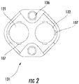
- FIG. 2 shows a collar 131 having a plurality of integrated raised weld tabs 107 according to an embodiment of the invention.
- Weld tabs 107 are shown oriented 90 degrees relative to one another.
- Collar portion 131 is secured to the base portion 111, by using bolts through bolt holes 136.
- Bolt holes 136 allow collar 131 to be removeably secured to the top of housing 101.
- the inner edge of the openings 121 and 122 are for receiving and securing solid bodies, such as bushings 105 and 106 shown in FIG. 1 . At least a portion of the inner edge of the opening 121 and 122 including an integral weld tab 107 raised above a level of the top surface 102.
- the addition of the raised weld tabs 107 to housings at the desired weld locations provides a controlled amount of material to be reflowed by a welder to create the desired weld between the sealed housing 101 and solid bodies such as bushings 105 and 106 shown in Fig. 1 .
- the thickness of the bushings associated with plungers 105 and 106 are generally ⁇ 2.5 mm, such as ⁇ 1.27 mm (.05 inches).
- the weld used can be TIG welding or other welding which provides sufficient energy to melt stainless steel.
- the weld tab provides a target for the arc energy delivered by the TIG welder.
- the weld tab also acts as a thermal shield so that excessive weld arc energy is not applied directly to the thin wall of the bushing or other body.
- weld tabs according to one embodiment of the invention provides of a fixed amount of weld material.
- the weld tab has been found to allow good welds to be achieved at lower energy levels, and even if a small gap exists between the body and the enclosure to be welded.
- results similar to this invention may be achievable through the use of filler rod.
- the use of filler rod is operator dependent.
- the present invention provides an essentially fixed amount of weld material.
- the material provided by weld tabs according to the present invention can comprise the same composition (e.g. same grade of stainless steel) as the housing and the solid body which thus provides better corrosion resistance than would be obtained from a filler of a different material or different grade of stainless steel.
- FIG. 3 shows a jet aircraft 300 comprising a sensing system including a switch 100 according to an embodiment of the present invention.
- Switch 100 is shown within the jet engine nacelle 305.
- the thrust reverser door state information is communicated by switch 100 via wires to full authority digital engine control (FADEC; main computer) 315, main flight computer 320 and cockpit 325. If the door is closed, the switch 100 senses whether or not the door is latched (locked). Cockpit can include a light 330 indicating thrust reverser door status to the pilot.
- FADEC full authority digital engine control
- wired connections 335 are shown, other connections can be used, such as fiber-optic connections.
- electrical continuity can exist between a particular pair of wires entering the switch (e.g. wires #1 and #2) when the thrust reverser door is closed, but when the door opens, the electrical contacts in switch 100 changes state, and there then can be continuity between a different pair of wires, (wires #1 and #3).
- the FADEC 315 can issue commands to actuators that open/close the thrust reverser door 310, commands to actuators that operate the latch mechanism, or commands to implement other functions.
- aircraft 300 can include other switches 100 according to the invention, such as located at cargo/passenger doors, around the landing gear, at the control surfaces (e.g. flaps).
- the invention is not limited to a specific number of sensing devices associated with the switch, nor to switches.
- a simplified prototype switch was fabricated using an embodiment of the present invention.
- a simplified collar was machined to provide a single central circular opening along with a plurality of integral weld tabs spaced apart along the edge of the opening.
- a 0.762 mm (.030 inch) thick bushing was provided. The collar was placed on a table to provide a backing. The bushing was inserted into the collar.
- the machining of the housing was designed to leave the desired size of weld tab at the desired weld locations.
- the weld tab size was .508 mm (.020 inch) high .508 mm (.020 inch) thick and 2.286 mm (.090 inch) wide.
- the processing conditions to weld the thin walled bushing to the machined stainless steel collar having raised integrated weld tabs were a TIG weld with arc setting of 35 amps and 0.2 seconds dwell per tab. These conditions were found to provide an acceptable weld without creating a measurable leak path through the bushing wall.
Landscapes
- Engineering & Computer Science (AREA)
- Manufacturing & Machinery (AREA)
- Physics & Mathematics (AREA)
- Plasma & Fusion (AREA)
- Mechanical Engineering (AREA)
- Arc Welding In General (AREA)
- Switch Cases, Indication, And Locking (AREA)
- Examining Or Testing Airtightness (AREA)
- Manufacture Of Switches (AREA)
- Casings For Electric Apparatus (AREA)
Description
- The invention relates to switching devices, and more particularly, the invention relates to switching devices having certain components secured to one another by weld material.
- Certain switches require a thin body (e.g. bushing) having a movable portion coupled into and rigidly affixed to a housing (sometimes referred to as an enclosure). Assembly of such switches generally requires a welding operation to affix the thin body to an opening in the enclosure adapted for receiving the body. In some applications, the body and the housing need to be maintained at a substantially sealed level to permit proper operation. Having the body and housing substantially sealed prevents ingress of environmental factors that can cause failure of the switch to properly conduct an electrical signal, such as due to corrosion.
- As known in the art, the body is inserted into an opening in a flat top portion of the housing to reach an o-ring which allows a seal to be formed. A welding operation then follows which removes material from the thin body and/or the housing to bond the respective components to one another.
- Known weld techniques, such as tungsten inert gas (TIG) welding, generally involve the arc being directed at the flat top surface of the housing in an attempt to push or splatter molten material on to the wall of the bushing to create a weld. Without a well defined target it was found by the present inventors that frequently excessive weld arc energy was inadvertently applied directly to the thin wall of the bushing, and a high level of operator skill was required to obtain acceptable welds that did not compromise the seal integrity of the switch.
- For example, during assembly of sealed plunger limit switches, poor yield can occur due to product failing the environmental seal test which tests for seal integrity. One requirement imposed for such switches in certain applications, such as for monitoring whether and to what extent cockpit door is ajar, is the military specification, that being ≤ 10-6 cm3/sec for the leak rate. The cause for these leaks has been traced by the present inventors generally to be holes or excessively thin regions in the body created in the thin bushing walls during welding of a housing to the bushing. What is needed is switches having a new thin body or housing arrangement and related process that is less operator dependent and thus more manufacturable that better preserves the seal integrity of the switches.
European Patent Application Publication No.EP0767477 describes a housing for a switch, suitable for use in computer laptops, the wall of the housing made of metal such as nickel, and having convolutions to accommodate compressive actuation displacement. The thickness of the wall is between 0.06 mm and 0.12 mm. The housing provides protection against water and dust. The housing is attached to the base by insert moulding, epoxy bonding, press fitting, soldering, or ultrasonic welding. - This Summary is provided to comply with 37 C.F.R. §1.73, requiring a summary of the invention briefly indicating the nature and substance of the invention. It is submitted with the understanding that it will not be used to interpret or limit the scope or meaning of the claims.
- A switching device includes a housing having an exterior surface with at least one opening in the surface. An inner edge of the opening for receiving and securing solid bodies, at least a portion of the inner edge of the opening including an integral weld tab raised above a level of the surface. A sensing body comprising a sensing structure is operable to sense at least one condition. The sensing body has an outer surface disposed partially within the housing and secured to the edge of the opening by the weld tab, wherein the weld tab provides weld material physically bonding the outer surface of the sensing body to the housing. The housing is a sealed housing providing a 25 °C leak rate of ≤10-6 cm3/s of helium at one atmosphere differential pressure between an interior and an exterior of the housing.
- In one embodiment the sensing structure comprises a movable portion which is operable to move inside the housing responsive to the condition, and the housing further comprising at least one electrical component for receiving the movable portion when the condition exceeds a threshold. The housing can comprise a sealed base portion and a collar portion, wherein the collar includes the integral weld tab(s) and is secured to the base portion. In one embodiment, the collar is removeably secured to the base portion.
- The weld tab can be oriented substantially normal to the exterior surface. In one embodiment, the weld tab comprises a plurality of spaced apart weld tabs. The sensing body can be a thin cylindrical bushing, such as having a wall thickness of less than 1.27 mm. In one embodiment the housing, the weld tab and the sensing body all comprise stainless steel.
- A method of manufacturing a switching device comprising a housing having an exterior surface including at least one opening in the surface, at least a portion of an inner edge of the opening including an integral weld tab raised above a level of the surface, and a sensing body, comprises the step of inserting a sensing body into the opening to reach partially within the housing. The weld tab is then welded to provide weld material to physically bond an outer surface of the sensing body to the housing. The housing is a sealed housing providing a 25 °C leak rate of ≤10-6 cm3/s of helium at one atmosphere differential pressure between an interior and an exterior of the housing. The welding step can comprise tungsten inert gas (TIG) welding and the housing, weld tab and the sensing body all comprise stainless steel. In one embodiment the sensing structure comprises a movable portion which moves inside the housing responsive to at least one condition, the housing further comprising at least one electrical component for receiving the movable portion when the condition exceeds a threshold.
- A multi-plunger limit switch comprises a sealed housing having an exterior surface with at least one opening in the surface, an inner edge of the opening for receiving and securing solid bodies, at least a portion of the inner edge of the opening including an integral weld tab raised above a level of the exterior surface, wherein the housing comprises a base portion and a collar portion. The collar includes the weld tab and is secured to the base portion. At least a first and second cylindrical sensing body are included and comprise a sensing structure including a plunger. The first and second sensing body having an outer surface disposed partially within the housing and are secured to the edge of the opening by the weld tab, wherein the weld tab provides weld material physically bonding the outer surface to the housing. The plunger is operable to moves inside the housing responsive to contact with an object, the housing further comprising electrical component operable to switch the witching device when a distal end of the plunger is received responsive to the object pushing against the plunger.
- A fuller understanding of the present invention and the features and benefits thereof will be accomplished upon review of the following detailed description together with the accompanying drawings, in which:
-
FIG. 1 is an isometric view of a switching device including weld tabs securing a pair of sensing structures to a collar which is affixed to a housing body, according to an embodiment of the invention. -
FIG. 2 shows a collar having a plurality of integrated raised weld tabs according to an embodiment of the invention. -
FIG. 3 is a depiction of a jet aircraft comprising a sensing system including a switch according to an embodiment of the present invention for sensing and transmitting thrust reverser door status information. -
FIG. 1 is a drawing of aswitching device 100 according to an embodiment of the present invention.Switching device 100 includes a housing 101 having an exterior surface shown as top surface 102 with at least one opening in the exterior surface (seecollar 131 shown inFIG. 2 havingopenings 121 and 122). As shown inFIG. 1 , housing 101 comprises a sealed base portion 111 and acollar portion 131 wherein the collar includes raisedintegral weld tabs 107. Collar 131 is secured to the base portion 111, such as using bolts 135, and can be sealed with an o-ring seal 138 therebetween. - As used herein, an "integral" weld tab refers to the weld tab material being essentially the same material (composition and morphology) as the structure the weld tabs are attached to, wherein no discernable interface exists between the weld tabs and the structure the weld tabs are attached to. Such a structure can be provided as described below by forming the material for weld tabs in the same forming process as the process to form the structure the weld tabs are attached to (
e.g. collar 131 inFIG. 1 ). Following welding, the morphology of weld material generally changes, particularly near the end of the weld tab remote from the structure the weld tabs are attached to. In one embodiment, following the weld operation, the weld tab portion proximate to the structure the weld tabs are attached thereto can remain essentially unchanged, thus remaining the essentially the same material (composition and morphology) as the material the structure and the weld tabs are attached to. - An inner edge of the openings of
collar 131 are for receiving and securing solid bodies, such asbushings 105 and 106 shown. At least a portion of the inner edge of opening 121 and 122 includes anintegral weld tab 107 which is raised above a level of the top surface 102. - The number, position and size of the
weld tabs 107 may vary depending on the design. In the embodiment shown inFIG. 1 , there are three (3) weld tabs shown to secure each bushing tocollar 131. The weld tabs for each bushing positioned about 90 degrees from one another. There are no weld tabs shown in the region between thebushings 105 and 106. This arrangement may be required when the design of the switching device requiresbushings 105 and 106 to be too close together to allow for welding to occur at points between the bushings. - In other embodiments, there may be more or
less weld tabs 107, and space permitting, weld tabs can be substantially equally spaced around the bushing. In one embodiment the weld tab is a continuous lip around the inner edge of theopenings -
Bushings 105 and 106 are part of sensingbodies 111 and 112, respectively. Sensingbodies 111 and 112 includemovable plungers weld tabs 107. Theweld tab 107 thus provides the weld material to physically bond the outer surface of thesensing body 111 and 112 to the housing 101. In one embodiment, all components are formed, or at least coated, by stainless steel. As known in the art, stainless steel refers to any of various steels alloyed with at least 10 percent chromium and sometimes containing other elements and that are resistant to corrosion or rusting associated with exposure to oxidants such as water and moist air. - Housing 101 is shown having
electrical components 132 inside for receivingmovable plungers 115 and 116 which move down when the condition sensed exceeds a threshold.Electrical components 132 generally comprise of one or more generally unsealed basic switch elements containing electrical contacts, and an actuating lever to transmit motion fromplungers 115 and 116 to the basic switch elements, and a bracket to retain basic switch elements and lever tobushings 105 or 106. Whenplungers 115 and 116 are sufficiently depressed, the electrical contacts inelectrical components 132 change state, and switchingdevice 100 indicates the condition sensed (e.g. produce an alarm or send a control signal to a controller). - The one or more
electrical components 132 within the housing 101 may be coupled electrically to components that are outside of the housing. For example, one or more electrical leads (not shown) may be coupled to suitable receptacles. To protect internal electrical components while permitting electrical connections with external components, the housing 101 may include one or more feedthroughs (not shown) that maintain the sealed nature of the housing 101. - As used herein, "sealed" generally refers to a leak rate defined by United States MIL-PRF-8805, symbol 4 (environmental), namely ≤10-6 cm3/s of helium at one atmosphere differential pressure between an interior and an exterior of portion of interest, such as the housing.
-
FIG. 2 shows acollar 131 having a plurality of integrated raisedweld tabs 107 according to an embodiment of the invention.Weld tabs 107 are shown oriented 90 degrees relative to one another.Collar portion 131 is secured to the base portion 111, by using bolts through bolt holes 136. Bolt holes 136 allowcollar 131 to be removeably secured to the top of housing 101. As noted above, the inner edge of theopenings bushings 105 and 106 shown inFIG. 1 . At least a portion of the inner edge of theopening integral weld tab 107 raised above a level of the top surface 102. - The addition of the raised
weld tabs 107 to housings at the desired weld locations provides a controlled amount of material to be reflowed by a welder to create the desired weld between the sealed housing 101 and solid bodies such asbushings 105 and 106 shown inFig. 1 . The thickness of the bushings associated withplungers 105 and 106 are generally < 2.5 mm, such as < 1.27 mm (.05 inches). The weld used can be TIG welding or other welding which provides sufficient energy to melt stainless steel. The weld tab provides a target for the arc energy delivered by the TIG welder. The weld tab also acts as a thermal shield so that excessive weld arc energy is not applied directly to the thin wall of the bushing or other body. Moreover, weld tabs according to one embodiment of the invention provides of a fixed amount of weld material. The weld tab has been found to allow good welds to be achieved at lower energy levels, and even if a small gap exists between the body and the enclosure to be welded. - As noted in the background, prior to the present invention, previous weld techniques generally required the arc to be directed at the flat top surface of the housing in an attempt to push or splatter material on to the wall of the solid body to be secured, such as a bushing, to create a weld. Without a well defined target it was a frequent occurrence that excessive weld arc energy was applied directly to the thin wall of the solid body, and a high level of operator skill was required to obtain acceptable welds.
- Results similar to this invention may be achievable through the use of filler rod. However, the use of filler rod is operator dependent. In contrast, the present invention provides an essentially fixed amount of weld material. The material provided by weld tabs according to the present invention can comprise the same composition (e.g. same grade of stainless steel) as the housing and the solid body which thus provides better corrosion resistance than would be obtained from a filler of a different material or different grade of stainless steel.
- Regarding aircraft applications, switches according to the invention can be used, for example, to detect the position of landing gear, control surfaces (flaps, rudder, and ailerons), doors (cargo, passenger, and thrust reverser).
FIG. 3 shows ajet aircraft 300 comprising a sensing system including aswitch 100 according to an embodiment of the present invention.Switch 100 is shown within thejet engine nacelle 305. In the embodiment shown the thrust reverser door state information is communicated byswitch 100 via wires to full authority digital engine control (FADEC; main computer) 315,main flight computer 320 andcockpit 325. If the door is closed, theswitch 100 senses whether or not the door is latched (locked). Cockpit can include a light 330 indicating thrust reverser door status to the pilot. - Although
wired connections 335 are shown, other connections can be used, such as fiber-optic connections. In oneswitch 100 arrangement, electrical continuity can exist between a particular pair of wires entering the switch (e.g. wires #1 and #2) when the thrust reverser door is closed, but when the door opens, the electrical contacts inswitch 100 changes state, and there then can be continuity between a different pair of wires, (wires #1 and #3). In operation ofaircraft 300, based on input from theswitch 100, theFADEC 315 can issue commands to actuators that open/close thethrust reverser door 310, commands to actuators that operate the latch mechanism, or commands to implement other functions. Although not shown,aircraft 300 can includeother switches 100 according to the invention, such as located at cargo/passenger doors, around the landing gear, at the control surfaces (e.g. flaps). - Although described related to a switch, specifically a dual plunger limit switch, the invention is not limited to a specific number of sensing devices associated with the switch, nor to switches.
- A simplified prototype switch was fabricated using an embodiment of the present invention. A simplified collar was machined to provide a single central circular opening along with a plurality of integral weld tabs spaced apart along the edge of the opening. A 0.762 mm (.030 inch) thick bushing was provided. The collar was placed on a table to provide a backing. The bushing was inserted into the collar.
- To produce the weld tabs, the machining of the housing was designed to leave the desired size of weld tab at the desired weld locations. In one embodiment, the weld tab size was .508 mm (.020 inch) high .508 mm (.020 inch) thick and 2.286 mm (.090 inch) wide. The processing conditions to weld the thin walled bushing to the machined stainless steel collar having raised integrated weld tabs were a TIG weld with arc setting of 35 amps and 0.2 seconds dwell per tab. These conditions were found to provide an acceptable weld without creating a measurable leak path through the bushing wall.
- It is to be understood that while the invention has been described in conjunction with the preferred specific embodiments thereof, that the foregoing description as well as the examples which follow are intended to illustrate and not limit the scope of the invention. Other aspects, advantages and modifications within the scope of the invention will be apparent to those skilled in the art to which the invention pertains.
- The Abstract of the Disclosure is provided to allow the reader to quickly ascertain the nature of the technical disclosure. It is submitted with the understanding that it will not be used to interpret or limit the scope or meaning of the following claims.
Claims (14)
- A switching device (100), comprising:a housing (101) having an exterior surface (102) with at least one opening (121, 122) in said surface (102), an inner edge of an opening of said at least one opening (121, 122) for receiving and securing a solid body, at least a portion of said inner edge of said opening (121, 122) including an integral weld tab (107) raised above a level of said surface (102);a sensing body (111, 112) comprising a sensing structure operable to sense at least one condition, said sensing body (111, 112) having an outer surface disposed partially within said housing (101) and secured to said edge of said opening by said weld tab (107), wherein said weld tab (107) provides weld material physically bonding said outer surface (102) of said sensing body (111, 112) to said housing (101); characterized in that said housing (101) is a sealed housing providing a 25 °C leak rate of ≤10-6 cm3/s of helium at one atmosphere differential pressure between an interior and an exterior of said housing (101).
- The device of claim 1, wherein said sensing structure comprises a movable portion which is operable to move inside said housing (101) responsive to said condition.
- The device of claim 2, said housing (101) further comprising at least one electrical component (132) for receiving said movable portion when said condition exceeds a threshold.
- The device of claim 1, wherein said housing (101) comprises a sealed base portion (119) and a collar portion (131), wherein said collar (131) includes said weld tab (107) and is secured to the base portion (119).
- The device of claim 1, wherein said weld tab (107) comprises a plurality of spaced apart weld tabs (107).
- The device of claim 1, wherein said sensing body (111, 112) is a cylindrical bushing (105, 106).
- The device of claim 6, wherein said housing (101), said weld tab (107) and said sensing body (111, 112) all comprise stainless steel.
- A method of manufacturing a switching device (100) comprising a housing (101) having an exterior surface (102) including at least one opening (121, 122) in said surface (102), at least a portion of an inner edge of said opening (121, 122) including an integral weld tab (107) raised above a level of said surface (102), and a sensing body (111, 112), comprising the steps of:inserting a sensing body (111, 112) into said opening (121, 122) to reach partially within said housing (101), andwelding said weld tab (107) to provide weld material to physically bond an outer surface (102) of said sensing body (111, 112) to said housing (101),wherein said housing (101) is a sealed housing providing a 25 °C leak rate of ≤10-6 cm3/s of helium at one atmosphere differential pressure between an interior and an exterior of said housing (101).
- The method of claim 8, wherein said welding comprises tungsten inert gas (TIG) welding.
- The method of claim 9, wherein said housing (101), said weld tab (107) and said sensing body (111, 112) all comprise stainless steel.
- The method of claim 8, wherein said sensing structure comprises a movable portion which moves inside said housing (101) responsive to at least one condition, said housing (101) further comprising at least one electrical component (132) for receiving said movable portion when said condition exceeds a threshold.
- The device of claim 1,
said housing (101) comprising a base portion (119) and a collar portion (131), wherein said collar (131) includes said weld tab (107) and is secured to said base portion (119);
wherein the sensing body (111, 112) comprises at least a first and a second cylindrical sensing body (111, 112) comprising a sensing structure including a plunger (116, 117);
wherein said plunger (116, 117) moves inside said housing (101) responsive to contact by an object, said housing (101) further comprising electrical component (132) operable to switch said switching device when a distal end of said plunger (116, 117) is received responsive to said object pushing against said plunger (116, 117). - The device of claim 12, wherein said weld tab (107) comprises a plurality of spaced apart weld tabs (107).
- The device of claim 12, wherein said sensing body (111, 112) has a wall thickness of less than 1.27 mm and said housing (101), said weld tab (107) and said sensing body (111, 112) all comprise stainless steel.
Applications Claiming Priority (1)
| Application Number | Priority Date | Filing Date | Title |
|---|---|---|---|
| US11/843,260 US7875820B2 (en) | 2007-08-22 | 2007-08-22 | Switching device having welding tabs for securing sensing structures to the device housing |
Publications (3)
| Publication Number | Publication Date |
|---|---|
| EP2028675A2 EP2028675A2 (en) | 2009-02-25 |
| EP2028675A3 EP2028675A3 (en) | 2010-01-06 |
| EP2028675B1 true EP2028675B1 (en) | 2018-08-08 |
Family
ID=39847032
Family Applications (1)
| Application Number | Title | Priority Date | Filing Date |
|---|---|---|---|
| EP08162646.7A Not-in-force EP2028675B1 (en) | 2007-08-22 | 2008-08-19 | Switching device having welding tabs for securing sensing structures to the device housing |
Country Status (3)
| Country | Link |
|---|---|
| US (1) | US7875820B2 (en) |
| EP (1) | EP2028675B1 (en) |
| RU (1) | RU2008134427A (en) |
Families Citing this family (1)
| Publication number | Priority date | Publication date | Assignee | Title |
|---|---|---|---|---|
| FR3016191B1 (en) * | 2014-01-08 | 2019-07-05 | Safran Aircraft Engines | METHOD AND COMPUTER PROGRAM FOR MONITORING A HYDRAULIC ACTUATOR PUSH INVERTER |
Citations (1)
| Publication number | Priority date | Publication date | Assignee | Title |
|---|---|---|---|---|
| EP0767477A2 (en) * | 1995-10-06 | 1997-04-09 | Ncr International Inc. | A switch |
Family Cites Families (12)
| Publication number | Priority date | Publication date | Assignee | Title |
|---|---|---|---|---|
| US2859313A (en) | 1956-12-14 | 1958-11-04 | Electro Snap Switch & Mfg Co | Hermetic seal for electrical switches |
| US3765173A (en) * | 1971-09-28 | 1973-10-16 | K G Industries | Hydraulic roll drive means for briquetters and compactors |
| US4709133A (en) | 1986-04-02 | 1987-11-24 | Jack Mainville | Welding apparatus for simultaneously applying parallel welds to workpieces |
| US5025667A (en) * | 1989-06-15 | 1991-06-25 | Texas Instruments Incorporated | Hermetic pressure sensor |
| FR2761625B1 (en) | 1997-04-07 | 1999-08-20 | Soc D Mecanique D Irigny | METHOD AND DEVICE FOR WELDING APPENDICES ON A CYLINDER TUBE |
| US6140907A (en) | 1998-08-20 | 2000-10-31 | Cts Corporation | Carbon fiber contacting position sensor |
| KR100534237B1 (en) | 1999-10-28 | 2005-12-08 | 후루카와 덴치 가부시키가이샤 | Method of producing lead storage batteries and jig for production thereof |
| US6514091B2 (en) | 2000-11-28 | 2003-02-04 | Sumitomo Wiring Systems, Ltd. | Electrical junction box for a vehicle |
| DE10237904B4 (en) | 2002-06-14 | 2007-05-31 | Ifm Electronic Gmbh | Electronic sensor and assembly of an electronic sensor and a fastener |
| US7326869B2 (en) * | 2004-10-22 | 2008-02-05 | Intergraph Hardware Technologies Company | Tactile feedback plunger switch |
| US7257445B2 (en) | 2004-10-27 | 2007-08-14 | Medtronic, Inc. | Welded connector attachment |
| DE102005015643A1 (en) * | 2005-04-05 | 2006-11-02 | Huf Hülsbeck & Fürst Gmbh & Co. Kg | actuator |
-
2007
- 2007-08-22 US US11/843,260 patent/US7875820B2/en active Active
-
2008
- 2008-08-19 EP EP08162646.7A patent/EP2028675B1/en not_active Not-in-force
- 2008-08-25 RU RU2008134427/09A patent/RU2008134427A/en not_active Application Discontinuation
Patent Citations (1)
| Publication number | Priority date | Publication date | Assignee | Title |
|---|---|---|---|---|
| EP0767477A2 (en) * | 1995-10-06 | 1997-04-09 | Ncr International Inc. | A switch |
Also Published As
| Publication number | Publication date |
|---|---|
| RU2008134427A (en) | 2010-02-27 |
| US20090050452A1 (en) | 2009-02-26 |
| US7875820B2 (en) | 2011-01-25 |
| EP2028675A2 (en) | 2009-02-25 |
| EP2028675A3 (en) | 2010-01-06 |
Similar Documents
| Publication | Publication Date | Title |
|---|---|---|
| US9865419B2 (en) | Pressure-controlled electrical relay device | |
| US4514616A (en) | Safety mounting device | |
| DE102015215384B4 (en) | Electrical bushing and its use | |
| DE102013202614B4 (en) | Accident-resistant implementation | |
| DE19837909C2 (en) | Protection device for a multi-rechargeable electrochemical battery | |
| US11000717B2 (en) | Sprinkler head | |
| US9897116B2 (en) | Method of detecting failure of a servo-valve, and a servo-valve applying the method | |
| EP3189255B1 (en) | A valve with a welded valve housing | |
| US4569365A (en) | Device for detecting the operation of a valve | |
| CN104912859A (en) | Valve assembly, in particular for space travel drive systems, which is closed when not actuated | |
| US7875820B2 (en) | Switching device having welding tabs for securing sensing structures to the device housing | |
| JP2016011752A (en) | Method and apparatus for containing sparks in a fuel tank | |
| US7055542B2 (en) | Valve with integrated actuator | |
| US9820614B1 (en) | Welding ground detection system and method | |
| EP3276320B1 (en) | Multi-condition sensor systems | |
| EP1740353A1 (en) | Overload protection device comprising an electric switching unit | |
| US20160184620A1 (en) | Method and mechanism for fast evacuation of a pressurized vessel | |
| EP1887599B1 (en) | Pressure switch | |
| EP2798313B1 (en) | Non-contact sensor | |
| EP3276321B1 (en) | Multi-condition sensor systems | |
| CN110355763A (en) | Position sensing component with collision warning function and with the mechanical arm of the component | |
| CN109356749B (en) | Variable thrust signal feedback system of solid rocket engine | |
| CN109637889B (en) | Temperature switch with adjustable temperature action point | |
| US20100019185A1 (en) | Electrically conductive bonding means for device components | |
| EP3982011A1 (en) | Gear box actuator with an internal air channel |
Legal Events
| Date | Code | Title | Description |
|---|---|---|---|
| PUAI | Public reference made under article 153(3) epc to a published international application that has entered the european phase |
Free format text: ORIGINAL CODE: 0009012 |
|
| 17P | Request for examination filed |
Effective date: 20080819 |
|
| AK | Designated contracting states |
Kind code of ref document: A2 Designated state(s): AT BE BG CH CY CZ DE DK EE ES FI FR GB GR HR HU IE IS IT LI LT LU LV MC MT NL NO PL PT RO SE SI SK TR |
|
| AX | Request for extension of the european patent |
Extension state: AL BA MK RS |
|
| PUAL | Search report despatched |
Free format text: ORIGINAL CODE: 0009013 |
|
| AK | Designated contracting states |
Kind code of ref document: A3 Designated state(s): AT BE BG CH CY CZ DE DK EE ES FI FR GB GR HR HU IE IS IT LI LT LU LV MC MT NL NO PL PT RO SE SI SK TR |
|
| AX | Request for extension of the european patent |
Extension state: AL BA MK RS |
|
| AKX | Designation fees paid |
Designated state(s): AT BE BG CH CY CZ DE DK EE ES FI FR GB GR HR HU IE IS IT LI LT LU LV MC MT NL NO PL PT RO SE SI SK TR |
|
| RAP1 | Party data changed (applicant data changed or rights of an application transferred) |
Owner name: HONEYWELL INTERNATIONAL INC. |
|
| 17Q | First examination report despatched |
Effective date: 20170316 |
|
| GRAP | Despatch of communication of intention to grant a patent |
Free format text: ORIGINAL CODE: EPIDOSNIGR1 |
|
| RIC1 | Information provided on ipc code assigned before grant |
Ipc: H01H 3/16 20060101ALI20180301BHEP Ipc: H01H 9/04 20060101AFI20180301BHEP Ipc: B23K 9/00 20060101ALI20180301BHEP Ipc: H01H 11/00 20060101ALI20180301BHEP |
|
| INTG | Intention to grant announced |
Effective date: 20180328 |
|
| GRAS | Grant fee paid |
Free format text: ORIGINAL CODE: EPIDOSNIGR3 |
|
| GRAA | (expected) grant |
Free format text: ORIGINAL CODE: 0009210 |
|
| AK | Designated contracting states |
Kind code of ref document: B1 Designated state(s): AT BE BG CH CY CZ DE DK EE ES FI FR GB GR HR HU IE IS IT LI LT LU LV MC MT NL NO PL PT RO SE SI SK TR |
|
| REG | Reference to a national code |
Ref country code: GB Ref legal event code: FG4D |
|
| REG | Reference to a national code |
Ref country code: CH Ref legal event code: EP Ref country code: AT Ref legal event code: REF Ref document number: 1027954 Country of ref document: AT Kind code of ref document: T Effective date: 20180815 |
|
| REG | Reference to a national code |
Ref country code: IE Ref legal event code: FG4D |
|
| REG | Reference to a national code |
Ref country code: DE Ref legal event code: R096 Ref document number: 602008056342 Country of ref document: DE |
|
| REG | Reference to a national code |
Ref country code: NL Ref legal event code: MP Effective date: 20180808 |
|
| REG | Reference to a national code |
Ref country code: LT Ref legal event code: MG4D |
|
| REG | Reference to a national code |
Ref country code: AT Ref legal event code: MK05 Ref document number: 1027954 Country of ref document: AT Kind code of ref document: T Effective date: 20180808 |
|
| PG25 | Lapsed in a contracting state [announced via postgrant information from national office to epo] |
Ref country code: NO Free format text: LAPSE BECAUSE OF FAILURE TO SUBMIT A TRANSLATION OF THE DESCRIPTION OR TO PAY THE FEE WITHIN THE PRESCRIBED TIME-LIMIT Effective date: 20181108 Ref country code: SE Free format text: LAPSE BECAUSE OF FAILURE TO SUBMIT A TRANSLATION OF THE DESCRIPTION OR TO PAY THE FEE WITHIN THE PRESCRIBED TIME-LIMIT Effective date: 20180808 Ref country code: GR Free format text: LAPSE BECAUSE OF FAILURE TO SUBMIT A TRANSLATION OF THE DESCRIPTION OR TO PAY THE FEE WITHIN THE PRESCRIBED TIME-LIMIT Effective date: 20181109 Ref country code: FI Free format text: LAPSE BECAUSE OF FAILURE TO SUBMIT A TRANSLATION OF THE DESCRIPTION OR TO PAY THE FEE WITHIN THE PRESCRIBED TIME-LIMIT Effective date: 20180808 Ref country code: LT Free format text: LAPSE BECAUSE OF FAILURE TO SUBMIT A TRANSLATION OF THE DESCRIPTION OR TO PAY THE FEE WITHIN THE PRESCRIBED TIME-LIMIT Effective date: 20180808 Ref country code: AT Free format text: LAPSE BECAUSE OF FAILURE TO SUBMIT A TRANSLATION OF THE DESCRIPTION OR TO PAY THE FEE WITHIN THE PRESCRIBED TIME-LIMIT Effective date: 20180808 Ref country code: PL Free format text: LAPSE BECAUSE OF FAILURE TO SUBMIT A TRANSLATION OF THE DESCRIPTION OR TO PAY THE FEE WITHIN THE PRESCRIBED TIME-LIMIT Effective date: 20180808 Ref country code: IS Free format text: LAPSE BECAUSE OF FAILURE TO SUBMIT A TRANSLATION OF THE DESCRIPTION OR TO PAY THE FEE WITHIN THE PRESCRIBED TIME-LIMIT Effective date: 20181208 Ref country code: BG Free format text: LAPSE BECAUSE OF FAILURE TO SUBMIT A TRANSLATION OF THE DESCRIPTION OR TO PAY THE FEE WITHIN THE PRESCRIBED TIME-LIMIT Effective date: 20181108 Ref country code: NL Free format text: LAPSE BECAUSE OF FAILURE TO SUBMIT A TRANSLATION OF THE DESCRIPTION OR TO PAY THE FEE WITHIN THE PRESCRIBED TIME-LIMIT Effective date: 20180808 |
|
| PG25 | Lapsed in a contracting state [announced via postgrant information from national office to epo] |
Ref country code: ES Free format text: LAPSE BECAUSE OF FAILURE TO SUBMIT A TRANSLATION OF THE DESCRIPTION OR TO PAY THE FEE WITHIN THE PRESCRIBED TIME-LIMIT Effective date: 20180808 Ref country code: LV Free format text: LAPSE BECAUSE OF FAILURE TO SUBMIT A TRANSLATION OF THE DESCRIPTION OR TO PAY THE FEE WITHIN THE PRESCRIBED TIME-LIMIT Effective date: 20180808 Ref country code: HR Free format text: LAPSE BECAUSE OF FAILURE TO SUBMIT A TRANSLATION OF THE DESCRIPTION OR TO PAY THE FEE WITHIN THE PRESCRIBED TIME-LIMIT Effective date: 20180808 |
|
| REG | Reference to a national code |
Ref country code: DE Ref legal event code: R119 Ref document number: 602008056342 Country of ref document: DE |
|
| REG | Reference to a national code |
Ref country code: CH Ref legal event code: PL |
|
| PG25 | Lapsed in a contracting state [announced via postgrant information from national office to epo] |
Ref country code: LI Free format text: LAPSE BECAUSE OF NON-PAYMENT OF DUE FEES Effective date: 20180831 Ref country code: EE Free format text: LAPSE BECAUSE OF FAILURE TO SUBMIT A TRANSLATION OF THE DESCRIPTION OR TO PAY THE FEE WITHIN THE PRESCRIBED TIME-LIMIT Effective date: 20180808 Ref country code: CH Free format text: LAPSE BECAUSE OF NON-PAYMENT OF DUE FEES Effective date: 20180831 Ref country code: LU Free format text: LAPSE BECAUSE OF NON-PAYMENT OF DUE FEES Effective date: 20180819 Ref country code: CZ Free format text: LAPSE BECAUSE OF FAILURE TO SUBMIT A TRANSLATION OF THE DESCRIPTION OR TO PAY THE FEE WITHIN THE PRESCRIBED TIME-LIMIT Effective date: 20180808 Ref country code: IT Free format text: LAPSE BECAUSE OF FAILURE TO SUBMIT A TRANSLATION OF THE DESCRIPTION OR TO PAY THE FEE WITHIN THE PRESCRIBED TIME-LIMIT Effective date: 20180808 Ref country code: RO Free format text: LAPSE BECAUSE OF FAILURE TO SUBMIT A TRANSLATION OF THE DESCRIPTION OR TO PAY THE FEE WITHIN THE PRESCRIBED TIME-LIMIT Effective date: 20180808 |
|
| REG | Reference to a national code |
Ref country code: BE Ref legal event code: MM Effective date: 20180831 |
|
| REG | Reference to a national code |
Ref country code: IE Ref legal event code: MM4A |
|
| PG25 | Lapsed in a contracting state [announced via postgrant information from national office to epo] |
Ref country code: SK Free format text: LAPSE BECAUSE OF FAILURE TO SUBMIT A TRANSLATION OF THE DESCRIPTION OR TO PAY THE FEE WITHIN THE PRESCRIBED TIME-LIMIT Effective date: 20180808 Ref country code: DK Free format text: LAPSE BECAUSE OF FAILURE TO SUBMIT A TRANSLATION OF THE DESCRIPTION OR TO PAY THE FEE WITHIN THE PRESCRIBED TIME-LIMIT Effective date: 20180808 |
|
| PLBE | No opposition filed within time limit |
Free format text: ORIGINAL CODE: 0009261 |
|
| STAA | Information on the status of an ep patent application or granted ep patent |
Free format text: STATUS: NO OPPOSITION FILED WITHIN TIME LIMIT |
|
| PG25 | Lapsed in a contracting state [announced via postgrant information from national office to epo] |
Ref country code: MC Free format text: LAPSE BECAUSE OF FAILURE TO SUBMIT A TRANSLATION OF THE DESCRIPTION OR TO PAY THE FEE WITHIN THE PRESCRIBED TIME-LIMIT Effective date: 20180808 |
|
| 26N | No opposition filed |
Effective date: 20190509 |
|
| GBPC | Gb: european patent ceased through non-payment of renewal fee |
Effective date: 20181108 |
|
| PG25 | Lapsed in a contracting state [announced via postgrant information from national office to epo] |
Ref country code: IE Free format text: LAPSE BECAUSE OF NON-PAYMENT OF DUE FEES Effective date: 20180819 Ref country code: DE Free format text: LAPSE BECAUSE OF NON-PAYMENT OF DUE FEES Effective date: 20190301 |
|
| PG25 | Lapsed in a contracting state [announced via postgrant information from national office to epo] |
Ref country code: BE Free format text: LAPSE BECAUSE OF NON-PAYMENT OF DUE FEES Effective date: 20180831 Ref country code: FR Free format text: LAPSE BECAUSE OF NON-PAYMENT OF DUE FEES Effective date: 20181008 Ref country code: SI Free format text: LAPSE BECAUSE OF FAILURE TO SUBMIT A TRANSLATION OF THE DESCRIPTION OR TO PAY THE FEE WITHIN THE PRESCRIBED TIME-LIMIT Effective date: 20180808 |
|
| PG25 | Lapsed in a contracting state [announced via postgrant information from national office to epo] |
Ref country code: GB Free format text: LAPSE BECAUSE OF NON-PAYMENT OF DUE FEES Effective date: 20181108 |
|
| PG25 | Lapsed in a contracting state [announced via postgrant information from national office to epo] |
Ref country code: MT Free format text: LAPSE BECAUSE OF NON-PAYMENT OF DUE FEES Effective date: 20180819 |
|
| PG25 | Lapsed in a contracting state [announced via postgrant information from national office to epo] |
Ref country code: TR Free format text: LAPSE BECAUSE OF FAILURE TO SUBMIT A TRANSLATION OF THE DESCRIPTION OR TO PAY THE FEE WITHIN THE PRESCRIBED TIME-LIMIT Effective date: 20180808 |
|
| PG25 | Lapsed in a contracting state [announced via postgrant information from national office to epo] |
Ref country code: PT Free format text: LAPSE BECAUSE OF FAILURE TO SUBMIT A TRANSLATION OF THE DESCRIPTION OR TO PAY THE FEE WITHIN THE PRESCRIBED TIME-LIMIT Effective date: 20180808 Ref country code: HU Free format text: LAPSE BECAUSE OF FAILURE TO SUBMIT A TRANSLATION OF THE DESCRIPTION OR TO PAY THE FEE WITHIN THE PRESCRIBED TIME-LIMIT; INVALID AB INITIO Effective date: 20080819 |
|
| PG25 | Lapsed in a contracting state [announced via postgrant information from national office to epo] |
Ref country code: CY Free format text: LAPSE BECAUSE OF FAILURE TO SUBMIT A TRANSLATION OF THE DESCRIPTION OR TO PAY THE FEE WITHIN THE PRESCRIBED TIME-LIMIT Effective date: 20180808 |