EP2028503A1 - Method for judging deterioration state of battery, deterioration judgment device and power supply system - Google Patents
Method for judging deterioration state of battery, deterioration judgment device and power supply system Download PDFInfo
- Publication number
- EP2028503A1 EP2028503A1 EP06766550A EP06766550A EP2028503A1 EP 2028503 A1 EP2028503 A1 EP 2028503A1 EP 06766550 A EP06766550 A EP 06766550A EP 06766550 A EP06766550 A EP 06766550A EP 2028503 A1 EP2028503 A1 EP 2028503A1
- Authority
- EP
- European Patent Office
- Prior art keywords
- battery
- health
- discharge
- impedance
- square wave
- Prior art date
- Legal status (The legal status is an assumption and is not a legal conclusion. Google has not performed a legal analysis and makes no representation as to the accuracy of the status listed.)
- Granted
Links
Images



Classifications
-
- G—PHYSICS
- G01—MEASURING; TESTING
- G01R—MEASURING ELECTRIC VARIABLES; MEASURING MAGNETIC VARIABLES
- G01R31/00—Arrangements for testing electric properties; Arrangements for locating electric faults; Arrangements for electrical testing characterised by what is being tested not provided for elsewhere
- G01R31/36—Arrangements for testing, measuring or monitoring the electrical condition of accumulators or electric batteries, e.g. capacity or state of charge [SoC]
- G01R31/392—Determining battery ageing or deterioration, e.g. state of health
Definitions
- the present invention relates to a method and device for determining state of health of the battery and a battery power supply system.
- the internal impedance of the battery can be obtained by the followings: Sine wave alternative current is applied to the battery in which neither charge nor discharge is implemented, then a response voltage thereto is detected, and a prescribed arithmetic computation is carried out applying the sine wave alternative current and the response voltage.
- Patent document 2 listed hereunder proposes a method for determining state of health of the sealed lead acid battery based on the internal impedance. There is described that the sealed lead acid battery is discharged at a prescribed constant cycle, discharge current of a constant frequency is applied thereto, and the discharge current waveform and the voltage response waveform are Fourier transformed to calculate the internal impedance.
- Patent document listed hereunder discloses that the impedance in an electrochemical device made with the electrodes inserted in the electrolyte often has frequency dependency so that it is necessary to repeatedly measure impedances in various many frequencies to.fully comprehend the characteristics of the device.
- the first method for calculating the internal impedance comprises the steps of applying the sine wave alternative current to the battery and calculating the internal impedance based on the response sine wave voltage variation. This method requires a large scale equipment to prepare and apply the sine wave alternative current, which causes serious problems in the cost and the size of the equipment, considering the application to the mobile phone or the application to be mounted on the vehicle.
- the method for calculating the internal impedance is proposed in which instead of directly applying the sine wave alternative current, the battery is caused to perform pulse discharge with a prescribed cycle, both of the current waveform and the voltage waveform are Fourier transformed, sine components with a prescribed cycle in both of the current waveform and the voltage waveform are extracted, and then the internal impedance is calculated based on the extracted components.
- any one of the conventional method for determining state of health of the battery requires high level of trigonometric function to calculate the internal impedance so that a high performance CPU with higher cost is required to implement the calculation which results in a heavy operational load, thus causing problem.
- the present invention is made to solve the above described problem and the object of the invention is to provide the method and the device for determining state of health of the battery, in addition to the power supply system using the device, which can remarkably reduce operational and processing load by expanding the data sampled at the time when the battery is caused to discharge square wave pulses into the square wave.
- the pseudo-impedance is compensated with a prescribed compensating equation to obtain a compensated impedance, and state of health of the battery is determined based on the compensated impedance.
- the battery is a rechargeable battery
- the rechargeable battery is caused to discharge or charge square wave pulses with a prescribed cycle at a prescribed current value.
- the battery is a rechargeable battery, and the rechargeable battery is caused to discharge or charge arbitrary waveform.
- the first embodiment of the device for determining state of health of a battery is the device including a discharge circuit to cause the battery to discharge pulses with prescribed cycles at prescribed current values; a memory to store sampled response voltages at a time of pulse-discharge; and a CPU inputting the response voltages from the memory, expanding the response voltages into orthogonal square wave components, dividing an amplitude of the square wave component of the response voltages by the current values of the pulse-discharge to obtain a pseudo-impedance, and determining state of health of the battery based on the pseudo-impedance.
- the second embodiment of the device for determining state of health of a battery is the device including a discharge circuit to cause the battery to discharge arbitrary waveform pulses; a memory to store a sampled current waveform and response voltage waveform at a time of pulse-discharge; and a CPU inputting the current waveform and the response voltage waveform from the memory, expanding the current waveform and the response voltage waveform into at least one orthogonal square wave component, dividing an amplitude of the square wave component of the response voltage waveform by an amplitude of the square wave component of the current waveform to obtain a pseudo-impedance, and determining state of health of the battery based on the pseudo-impedance.
- the CPU compensates the pseudo-impedance with a prescribed compensating equation to obtain a compensated impedance, and state of health of the battery is determined based on the compensated impedance.
- the battery is a rechargeable battery
- a charge circuit to cause the rechargeable battery to charge pulses with prescribed cycles at prescribed current values is further included
- the memory stores sampled response voltages at a time of a pulse-discharge or pulse-charge.
- the battery is a rechargeable battery
- a charge circuit to cause the rechargeable battery to charge arbitrary waveform pulses is further included
- the memory stores sampled response voltage at a time of a pulse-discharge or pulse-charge.
- One of the embodiments of the power supply system is the power supply system including the above described device for determining state of health of a battery in the battery.
- the present invention it is possible to provide the method for determining state of health of the battery which can remarkably reduce operational and processing load by expanding the sampled data into the square wave.
- a CPU with relatively lower function can be used so as to provide the device for determining state of health of the battery and the power supply system using the same at low cost.
- Fig. 1 is a block diagram depicting the first embodiment of the method for determining state of health of the battery of the invention.
- the discharge means 2 causes the battery 1 to discharge square wave pulses with a prescribed cycle at the prescribed current value 7. This can be easily realized by opening and closing the switch in the prescribed cycle.
- the square wave expanding means 3 implements sampling of the response voltage 6 when the battery 1 is caused to pulse-discharge by the discharge means 2, and expands into the orthogonal square wave components.
- the orthogonal square wave is expressed in general by the followings:
- T is the cycle of the fundamental wave (i.e., the wave with the lowest frequency), and equal to the cycle of the pulse
- the square wave expanding means 3 calculates, for example, the coefficient al in the fundamental frequency based on the above equation.
- the pseudo-impedance calculating means 4 inputs the coefficient al calculated by the square wave expanding means 3 on one hand, and inputs the current value 7 from the discharge means 2, when the battery 1 is caused to pulse-discharge, on the other hand.
- the pseudo-impedance 8 is calculated by dividing the coefficient a1 by the current value 7, without implementing the trigonometric function operation. It is possible to perform the sampling of the current as the current value 7 when the battery 1 is caused to pulse-discharge, and apply the same.
- the state of health determining means 5 inputs the pseudo-impedance calculated by the pseudo-impedance calculating means 4, and determines state of health of the battery 1 (i.e., whether the battery 1 is deteriorated or not), by a method of determining whether the pseudo-impedance 8 exceeds a prescribed limit or not, for example.
- the true (practical) impedance is obtained and applied to determine state of health of the battery
- the pseudo-impedance described above is applied to determine state of health of the battery 1, in place of the true impedance. This is based on a new finding that there is a linear correlation between the pseudo-impedance obtained by square wave expanding in the invention and the impedance obtained by the sine wave expanding (i.e., Fourier expanding) in the prior art.
- Fig. 2 The correlation between the pseudo-impedance obtained by the square wave expanding and the impedance obtained by the sine wave expanding is depicted in Fig. 2 .
- the pseudo-impedance obtained by the square wave expanding is expressed by x
- the impedance obtained by the sine wave expanding is expressed by y
- the coefficient c and d can be decided from Fig. 2 .
- the response voltage 6 is expanded into the square waves applying the equations 1 to 5
- it becomes possible to remarkably reduce the operational load of CPU since the operation is implemented for the respective zones which have the identical value in the equation 1 or 2 to simplify the processing, and in addition, it requires no operation of the trigonometric function which has a heavy operational load.
- the second embodiment of the method for determining state of health of the battery of the invention is described with reference to Fig. 3 .
- the pulse discharge with arbitrary waveform is applied to determine state of health of the battery, in place of the pulse discharge with the square wave.
- the discharge means 11 causes the battery 1 to pulse-discharge with a prescribed waveform.
- the above-described prescribed waveform can be arbitrarily prepared and applied.
- the arbitrarily prepared waveform can be set in advance in the discharge means 11.
- the square wave can be surely used as the arbitrary waveform.
- the first square wave expanding means 12 implements sampling of the response voltage 16 when the battery 1 is caused to pulse-discharge by the discharge means 11, and expands into the orthogonal square wave component.
- the square wave expanding means 12 calculates, for example, the coefficient a1' (the coefficient a1 in the first embodiment) in the fundamental frequency, in the same manner.
- the second square wave expanding means 13 implements sampling of the current 17 when the battery 1 is caused to pulse-discharge by the discharge means 11, and expands into the orthogonal square wave component. Although the equation 3 expands the response voltage into the square wave component, the current 17 can be expanded into the square wave component in the same manner as in the equation 3. Concerning the current 17, the second square wave expanding means 13 calculates, for example, the coefficient a1" (discriminated from the coefficient a1, a1') in the fundamental frequency, in the same manner.
- the pseudo-impedance calculating means 14 inputs the coefficient a1' calculated by the first square wave expanding means 12 and the coefficient a1'' calculated by the second square wave expanding means 13.
- the pseudo-impedance 18 is calculated by dividing the coefficient a1' by the coefficient a1''.
- the battery 1 is caused to pulse-charge to determine state of health of the battery 1
- the battery can be caused to pulse-charge to determine state of health of the battery.
- the charge means to cause the battery to pulse-charge is to be installed in place of the charge means 2 in the first embodiment or the charge means 11 in the second embodiment.
- the method is to be designed such that the pulse discharge and the pulse charge can be selectively performed.
- FIG. 4 is a block diagram showing the device for determining state of health of the battery which realizes the method for determining state of health of the battery in the first embodiment of the invention.
- the device 21 for determining state of health of the battery comprises a CPU 22, a memory 23 and a discharge circuit 24.
- the discharge circuit 24 corresponds in function to the discharge means 2.
- a charge circuit can be further added to the device 21 to be applied for determining state of health of the battery.
- a program of determining state of health of the battery to realize the method for determining state of health of the battery in the first embodiment of the invention, and a program of voltage-sampling to perform sampling of the voltage measured by the voltmeter 25 are installed in the CPU 22, and each of the programs is processed in response to the requirement of the outside.
- the pulse-discharge with the substantial square wave is requested to the discharge circuit 24.
- the response voltage at the time is measured by the voltmeter 25. Then, the measured response voltage is sampled by means of the program of voltage-sampling to perform sampling of the voltage, and stored in the memory 23.
- the response voltage is expanded into the square wave by means of the square wave expanding means 3 in the program of determining state of health of the battery.
- the pseudo-impedance calculating means 4 and the determining means 5 of state of health are executed to determine state of health of the battery 1.
- FIG. 5 Another device for determining state of health of the battery to realize the method for determining state of health of the battery in the second embodiment of the invention is described with reference the block diagram depicted in Fig. 5 .
- the construction of the device 31 for determining state of health of the battery is the same as the device 21 for determining state of health of the battery except that the current is inputted from the ammeter 32.
- the device 31 is the same as the device 21 in that the charge circuit is further added to the device 31 in case that the battery 1 is the rechargeable battery.
- a program of current-sampling to perform sampling of the current measured by the ammeter 32 and to store the same in the memory 23 are installed in the CPU 22 of the device 31 for determining state of health of the battery, and each of the programs is processed in response to the requirement of the outside.
- the pulse-discharge with arbitrary waveform is requested to the discharge circuit 24.
- the current and the response voltage at the time are respectively measured by the ammeter 32 and the voltmeter 25.
- the measured current and the response voltage are sampled by means of the program of current-sampling and the program of voltage-sampling to perform sampling of the current and the voltage, and stored in the memory 23.
- the processing of the other program of determining state of health of the battery is implemented in the same manner as that in the device 21 for determining state of health of the battery to determine state of health of the battery 1.
- Fig. 6 depicts one example of a power supply system including the above described device 31 for determining state of health of the battery of the invention.
- the example as depicted in Fig. 6 is the power supply system 41 in which the battery 1 is the rechargeable battery, and the device 31 for determining state of health of the battery includes the charge circuit 42 in addition to the charge circuit 24. It is also possible to provide the power supply system including the device 21 for determining state of health of the battery, as well as the example depicted in Fig. 6 .
- a CPU with relatively lower performance can be applied to the CPU 22 in the above described device 21 or 31 for determining state of health of the battery of the invention.
- the response voltage or the like is Fourier-transformed with the use of the trigonometric function which has a heavy operational load.
- the response voltage or the like is processed by means of the square wave expanding, thus enabling to remarkably reduce the load of the CPU. Accordingly, the requirement of the performance of the CPU installed in the device 21 or 31 for determining state of health of the battery can be lowered comparing with the conventional device, thus enabling to largely lower the cost for the CPU.
Landscapes
- Physics & Mathematics (AREA)
- General Physics & Mathematics (AREA)
- Secondary Cells (AREA)
- Tests Of Electric Status Of Batteries (AREA)
Abstract
Description
- The present invention relates to a method and device for determining state of health of the battery and a battery power supply system.
- Various technologies of the method for determining state of health of the battery have been developed in a rechargeable battery in particular. Among them, the technology to determine state of health of the battery based on a measured internal impedance attracts attention (refer to
Patent document 1 listed hereunder, for example). The internal impedance of the battery can be obtained by the followings: Sine wave alternative current is applied to the battery in which neither charge nor discharge is implemented, then a response voltage thereto is detected, and a prescribed arithmetic computation is carried out applying the sine wave alternative current and the response voltage. - For example,
Patent document 2 listed hereunder proposes a method for determining state of health of the sealed lead acid battery based on the internal impedance. There is described that the sealed lead acid battery is discharged at a prescribed constant cycle, discharge current of a constant frequency is applied thereto, and the discharge current waveform and the voltage response waveform are Fourier transformed to calculate the internal impedance. - Patent document listed hereunder discloses that the impedance in an electrochemical device made with the electrodes inserted in the electrolyte often has frequency dependency so that it is necessary to repeatedly measure impedances in various many frequencies to.fully comprehend the characteristics of the device.
- The first method for calculating the internal impedance comprises the steps of applying the sine wave alternative current to the battery and calculating the internal impedance based on the response sine wave voltage variation. This method requires a large scale equipment to prepare and apply the sine wave alternative current, which causes serious problems in the cost and the size of the equipment, considering the application to the mobile phone or the application to be mounted on the vehicle.
- To solve the problems mentioned above, the method for calculating the internal impedance is proposed in which instead of directly applying the sine wave alternative current, the battery is caused to perform pulse discharge with a prescribed cycle, both of the current waveform and the voltage waveform are Fourier transformed, sine components with a prescribed cycle in both of the current waveform and the voltage waveform are extracted, and then the internal impedance is calculated based on the extracted components. Thus, there is no need to produce the sine wave alternative current so as to enable to realize downsizing and lower cost in the detecting equipment.
- Patent document 1: Japanese Patent Application Publication Hei
10(1998)-56744 - Patent document 2: Japanese Patent No.
3367320 - Patent document 3: Japanese Patent Application Publication Show
53(1978)-070472 - However, any one of the conventional method for determining state of health of the battery requires high level of trigonometric function to calculate the internal impedance so that a high performance CPU with higher cost is required to implement the calculation which results in a heavy operational load, thus causing problem.
- The present invention is made to solve the above described problem and the object of the invention is to provide the method and the device for determining state of health of the battery, in addition to the power supply system using the device, which can remarkably reduce operational and processing load by expanding the data sampled at the time when the battery is caused to discharge square wave pulses into the square wave.
- The first embodiment of the method for determining state of health of a battery is the method comprising the steps of:
- causing the battery to discharge square wave pulses with a prescribed cycle at a prescribed current value;
- sampling response voltages at a time of a pulse-discharge;
- expanding sampled response voltages into orthogonal square wave components;
- dividing an amplitude of the square wave component by the current value of the pulse-discharge to obtain a pseudo-impedance; and
- determining state of health of the battery based on the pseudo-impedance.
- The second embodiment of the method for determining state of health of a battery is the method comprising the steps of:
- causing the battery to discharge arbitrary waveform pulses;
- sampling respective current waveform and response voltage waveform at a time of pulse-discharge;
- expanding sampled current waveform and response voltage waveform into at least one orthogonal square wave component; dividing an amplitude of the square wave component of the
- response voltage waveform by an amplitude of the square wave component of the current waveform to obtain a pseudo-impedance;
- and
- determining state of health of the battery based on the pseudo-impedance.
- In the third embodiment of the method for determining state of health of a battery, the pseudo-impedance is compensated with a prescribed compensating equation to obtain a compensated impedance, and state of health of the battery is determined based on the compensated impedance.
- In the fourth embodiment of the method for determining state of health of a battery, the battery is a rechargeable battery, and the rechargeable battery is caused to discharge or charge square wave pulses with a prescribed cycle at a prescribed current value.
- In the fifth embodiment of the method for determining state of health of a battery, the battery is a rechargeable battery, and the rechargeable battery is caused to discharge or charge arbitrary waveform.
- The first embodiment of the device for determining state of health of a battery is the device including a discharge circuit to cause the battery to discharge pulses with prescribed cycles at prescribed current values; a memory to store sampled response voltages at a time of pulse-discharge; and a CPU inputting the response voltages from the memory, expanding the response voltages into orthogonal square wave components, dividing an amplitude of the square wave component of the response voltages by the current values of the pulse-discharge to obtain a pseudo-impedance, and determining state of health of the battery based on the pseudo-impedance.
- The second embodiment of the device for determining state of health of a battery is the device including a discharge circuit to cause the battery to discharge arbitrary waveform pulses; a memory to store a sampled current waveform and response voltage waveform at a time of pulse-discharge; and a CPU inputting the current waveform and the response voltage waveform from the memory, expanding the current waveform and the response voltage waveform into at least one orthogonal square wave component, dividing an amplitude of the square wave component of the response voltage waveform by an amplitude of the square wave component of the current waveform to obtain a pseudo-impedance, and determining state of health of the battery based on the pseudo-impedance.
- In the third embodiment of the device for determining state of health of a battery, the CPU compensates the pseudo-impedance with a prescribed compensating equation to obtain a compensated impedance, and state of health of the battery is determined based on the compensated impedance.
- In the fourth embodiment of the device for determining state of health of a battery, the battery is a rechargeable battery, a charge circuit to cause the rechargeable battery to charge pulses with prescribed cycles at prescribed current values is further included, and the memory stores sampled response voltages at a time of a pulse-discharge or pulse-charge.
- In the fifth embodiment of the device for determining state of health of a battery, the battery is a rechargeable battery, a charge circuit to cause the rechargeable battery to charge arbitrary waveform pulses is further included, and the memory stores sampled response voltage at a time of a pulse-discharge or pulse-charge.
- One of the embodiments of the power supply system is the power supply system including the above described device for determining state of health of a battery in the battery.
- According to the present invention, it is possible to provide the method for determining state of health of the battery which can remarkably reduce operational and processing load by expanding the sampled data into the square wave. In addition, it is possible to determine state of health of the battery by expanding into the square wave to obtain the pseudo-impedance and applying thereof with the same preciseness as the method applying the impedance.
- Furthermore, since the operational load can be remarkably reduced by the method for determining state of health of the battery of the invention, a CPU with relatively lower function can be used so as to provide the device for determining state of health of the battery and the power supply system using the same at low cost.
-
-
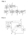
Fig. 1 is a block diagram depicting the first embodiment of the method for determining state of health of the battery of the invention; -
Fig. 2 is a graph showing correlation between pseudo-impedance obtained by expanding into the square wave and the impedance obtained by expanding into sine wave; -
Fig. 3 is a block diagram depicting the second embodiment of the method for determining state of health of the battery of the invention; -
Fig. 4 is a block diagram showing the device for determining state of health of the battery which realizes the method for determining state of health of the battery in the first embodiment of the invention; -
Fig. 5 is a block diagram showing the device for determining state of health of the battery which realizes the method for determining state of health of the battery in the second embodiment of the invention; and -
Fig. 6 is a block diagram showing a power supply system including the device for determining state of health of the battery of the invention. -
- 1
- battery
- 2, 11
- discharge means
- 3
- square wave expanding means
- 4, 14
- pseudo-impedance calculating means
- 5, 15
- state of health determining means
- 6, 16
- response voltage
- 7, 17
- current
- 8, 18
- pseudo-impedance
- 12
- first square wave expanding means
- 13
- second square wave expanding means
- 21, 31
- device for determining state of health
- 22
- CPU
- 23
- memory
- 24
- discharge circuit
- 25
- voltmeter
- 32
- ammeter
- 41
- power supply system
- 42
- charge circuit
-
Fig. 1 is a block diagram depicting the first embodiment of the method for determining state of health of the battery of the invention. The discharge means 2 causes thebattery 1 to discharge square wave pulses with a prescribed cycle at the prescribed current value 7. This can be easily realized by opening and closing the switch in the prescribed cycle. - The square wave expanding means 3 implements sampling of the
response voltage 6 when thebattery 1 is caused to pulse-discharge by the discharge means 2, and expands into the orthogonal square wave components. The orthogonal square wave is expressed in general by the followings: -


- When the
response voltage 6 is expressed by V(t), applying the orthogonal square wave expressed by theequations 
- The coefficient in the equation 3 can be obtained by the following equation:


The operation of the above respective integrals can be calculated, in the same manner as the discrete Fourier expansion in the sine wave, by sampling V(t) for one cycle (= T) at the prescribed sampling interval Δt, and operating quadrature by parts. The square wave expanding means 3 calculates, for example, the coefficient al in the fundamental frequency based on the above equation. - The pseudo-impedance calculating means 4 inputs the coefficient al calculated by the square wave expanding means 3 on one hand, and inputs the current value 7 from the discharge means 2, when the
battery 1 is caused to pulse-discharge, on the other hand.
Thepseudo-impedance 8 is calculated by dividing the coefficient a1 by the current value 7, without implementing the trigonometric function operation. It is possible to perform the sampling of the current as the current value 7 when thebattery 1 is caused to pulse-discharge, and apply the same. - The state of
health determining means 5 inputs the pseudo-impedance calculated by the pseudo-impedance calculating means 4, and determines state of health of the battery 1 (i.e., whether thebattery 1 is deteriorated or not), by a method of determining whether thepseudo-impedance 8 exceeds a prescribed limit or not, for example. - In the prior art, the true (practical) impedance is obtained and applied to determine state of health of the battery, whereas in the present invention, the pseudo-impedance described above is applied to determine state of health of the
battery 1, in place of the true impedance. This is based on a new finding that there is a linear correlation between the pseudo-impedance obtained by square wave expanding in the invention and the impedance obtained by the sine wave expanding (i.e., Fourier expanding) in the prior art. - The correlation between the pseudo-impedance obtained by the square wave expanding and the impedance obtained by the sine wave expanding is depicted in
Fig. 2 . When the pseudo-impedance obtained by the square wave expanding is expressed by x, and the impedance obtained by the sine wave expanding is expressed by y, it is evident fromFig. 2 that the linear relation as expressed by the equation y = c · x + d is substantially satisfied. Here, the coefficient c and d can be decided fromFig. 2 . - As described above, according to the first embodiment of the invention, it becomes possible to determine state of health of the battery with the substantially same precision as the method applying the true impedance. Furthermore, in case that the
response voltage 6 is expanded into the square waves applying theequations 1 to 5, it becomes possible to remarkably reduce the operational load of CPU, since the operation is implemented for the respective zones which have the identical value in theequation - Although the
pseudo-impedance 8 is applied as it is for determining state of health of thebattery 1 in the first embodiment of the invention, it is also possible to apply the impedance compensated based on the correlation equation between the square waves expanded pseudo-impedance and the sine wave expanded impedance as depicted inFig. 2 . More specifically, the above described correlation equation y = c · x + d is obtained fromFig. 2 , then the pseudo-impedance s compensated by the correlation equation, and then thus compensated impedance is applied to determine state of health of thebattery 1. Accordingly, the precision of the determination can be remarkably improved. - The second embodiment of the method for determining state of health of the battery of the invention is described with reference to
Fig. 3 . In this embodiment, the pulse discharge with arbitrary waveform is applied to determine state of health of the battery, in place of the pulse discharge with the square wave. - The discharge means 11 causes the
battery 1 to pulse-discharge with a prescribed waveform. The above-described prescribed waveform can be arbitrarily prepared and applied. The arbitrarily prepared waveform can be set in advance in the discharge means 11. The square wave can be surely used as the arbitrary waveform. - The first square wave expanding means 12 implements sampling of the
response voltage 16 when thebattery 1 is caused to pulse-discharge by the discharge means 11, and expands into the orthogonal square wave component. Here, the square wave expanding means 12 calculates, for example, the coefficient a1' (the coefficient a1 in the first embodiment) in the fundamental frequency, in the same manner. - The second square wave expanding means 13 implements sampling of the current 17 when the
battery 1 is caused to pulse-discharge by the discharge means 11, and expands into the orthogonal square wave component. Although the equation 3 expands the response voltage into the square wave component, the current 17 can be expanded into the square wave component in the same manner as in the equation 3. Concerning the current 17, the second square wave expanding means 13 calculates, for example, the coefficient a1" (discriminated from the coefficient a1, a1') in the fundamental frequency, in the same manner. - The pseudo-impedance calculating means 14 inputs the coefficient a1' calculated by the first square wave expanding means 12 and the coefficient a1'' calculated by the second square
wave expanding means 13. The pseudo-impedance 18 is calculated by dividing the coefficient a1' by the coefficient a1''. - The state of
health determining means 15 inputs the pseudo-impedance 18 calculated by the pseudo-impedance calculating means 14, and determines state of health of the battery 1 (i.e., whether thebattery 1 is deteriorated or not), by the same method as that in the first embodiment. Furthermore, as the same as the first embodiment, the pseudo-impedance is compensated by the correlation equation y = c · x + d, and then thus compensated impedance is applied to determine state of health of thebattery 1. Accordingly, the precision of the determination can be remarkably improved. - The embodiment in which the
battery 1 is caused to pulse-charge to determine state of health of thebattery 1 is described above.
In case that the battery is a rechargeable battery, thebattery 1 can be caused to pulse-charge to determine state of health of the battery. To do so, the charge means to cause the battery to pulse-charge is to be installed in place of the charge means 2 in the first embodiment or the charge means 11 in the second embodiment. Alternatively, the method is to be designed such that the pulse discharge and the pulse charge can be selectively performed. - A device for determining state of health of the battery of the invention is described with reference to the drawings.
Fig. 4 is a block diagram showing the device for determining state of health of the battery which realizes the method for determining state of health of the battery in the first embodiment of the invention. Thedevice 21 for determining state of health of the battery comprises aCPU 22, amemory 23 and adischarge circuit 24. Thedischarge circuit 24 corresponds in function to the discharge means 2. In case that thebattery 1 is the rechargeable battery, a charge circuit can be further added to thedevice 21 to be applied for determining state of health of the battery. - A program of determining state of health of the battery to realize the method for determining state of health of the battery in the first embodiment of the invention, and a program of voltage-sampling to perform sampling of the voltage measured by the
voltmeter 25 are installed in theCPU 22, and each of the programs is processed in response to the requirement of the outside. - When the processing of the program of determining state of health of the battery is started, the pulse-discharge with the substantial square wave is requested to the
discharge circuit 24. When the pulse-discharge is implemented in thedischarge circuit 24, the response voltage at the time is measured by thevoltmeter 25. Then, the measured response voltage is sampled by means of the program of voltage-sampling to perform sampling of the voltage, and stored in thememory 23. - Following the sampling of the response voltage for a prescribed time period by means of the program of voltage-sampling to perform sampling of the voltage, the response voltage is expanded into the square wave by means of the square wave expanding means 3 in the program of determining state of health of the battery. Following that, the pseudo-impedance calculating means 4 and the determining
means 5 of state of health are executed to determine state of health of thebattery 1. - Another device for determining state of health of the battery to realize the method for determining state of health of the battery in the second embodiment of the invention is described with reference the block diagram depicted in
Fig. 5 . The construction of thedevice 31 for determining state of health of the battery is the same as thedevice 21 for determining state of health of the battery except that the current is inputted from theammeter 32. In addition, thedevice 31 is the same as thedevice 21 in that the charge circuit is further added to thedevice 31 in case that thebattery 1 is the rechargeable battery. - In addition to a program of determining state of health of the battery and a program of voltage-sampling to realize the method for determining state of health of the battery in the second embodiment of the invention, a program of current-sampling to perform sampling of the current measured by the
ammeter 32 and to store the same in thememory 23 are installed in theCPU 22 of thedevice 31 for determining state of health of the battery, and each of the programs is processed in response to the requirement of the outside. - When the processing of the program of determining state of health of the battery is started, first of all, the pulse-discharge with arbitrary waveform is requested to the
discharge circuit 24. When the pulse-discharge is implemented in thedischarge circuit 24, the current and the response voltage at the time are respectively measured by theammeter 32 and thevoltmeter 25. Then, the measured current and the response voltage are sampled by means of the program of current-sampling and the program of voltage-sampling to perform sampling of the current and the voltage, and stored in thememory 23. - Following the sampling of the current and the response voltage for a prescribed time period by means of the program of current-sampling and the program of voltage-sampling to perform sampling of the current and the voltage, the processing of the other program of determining state of health of the battery is implemented in the same manner as that in the
device 21 for determining state of health of the battery to determine state of health of thebattery 1. -
Fig. 6 depicts one example of a power supply system including the above describeddevice 31 for determining state of health of the battery of the invention. The example as depicted inFig. 6 is thepower supply system 41 in which thebattery 1 is the rechargeable battery, and thedevice 31 for determining state of health of the battery includes thecharge circuit 42 in addition to thecharge circuit 24. It is also possible to provide the power supply system including thedevice 21 for determining state of health of the battery, as well as the example depicted inFig. 6 . - A CPU with relatively lower performance can be applied to the
CPU 22 in the above describeddevice device - The specification is based on the Japanese Patent Application No.
2005-108,565 filed on April 5, 2005
Claims (11)
- A method for determining state of health of a battery comprising the steps of:causing the battery to discharge square wave pulses with a prescribed cycle at a prescribed current value;sampling response voltages at a time of a pulse-discharge;expanding sampled response voltages into orthogonal square wave components;dividing an amplitude of the square wave component by the current value of the pulse-discharge to obtain a pseudo-impedance; anddetermining state of health of the battery based on the pseudo-impedance.
- A method for determining state of health of a battery comprising the steps of:causing the battery to discharge arbitrary waveform pulses;sampling respective current waveform and response voltage waveform at a time of pulse-discharge;expanding sampled current waveform and response voltage waveform into at least one orthogonal square wave component;dividing an amplitude of the square wave component of the response voltage waveform by an amplitude of the square wave component of the current waveform to obtain a pseudo-impedance;anddetermining state of health of the battery based on the pseudo-impedance.
- The method for determining state of health of a battery according to claim 1 or 2, wherein the pseudo-impedance is compensated with a prescribed compensating equation to obtain a compensated impedance, and state of health of the battery is determined based on the compensated impedance.
- The method for determining state of health of a battery according to claim 1 or 3, wherein the battery is a rechargeable battery, and the rechargeable battery is caused to discharge or charge square wave pulses with a prescribed cycle at a prescribed current value.
- The method for determining state of health of a battery according to claim 2 or 3, wherein the battery is a rechargeable battery, and the rechargeable battery is caused to discharge or charge arbitrary waveform.
- A device for determining state of health of a battery including a discharge circuit to cause the battery to discharge pulses with prescribed cycles at prescribed current values; a memory to store sampled response voltages at a time of pulse-discharge; and a CPU inputting the response voltages from the memory, expanding the response voltages into orthogonal square wave components, dividing an amplitude of the square wave component of the response voltages by the current values of the pulse-discharge to obtain a pseudo-impedance, and determining state of health of the battery based on the pseudo-impedance.
- A device for determining state of health of a battery including a discharge circuit to cause the battery to discharge arbitrary waveform pulses; a memory to store a sampled current waveform and response voltage waveform at a time of pulse-discharge; and a CPU inputting the current waveform and the response voltage waveform from the memory, expanding the current waveform and the response voltage waveform into at least one orthogonal square wave component, dividing an amplitude of the square wave component of the response voltage waveform by an amplitude of the square wave component of the current waveform to obtain a pseudo-impedance, and determining state of health of the battery based on the pseudo-impedance.
- The device for determining state of health of a battery according to claim 6 or 7, wherein the CPU compensates the pseudo-impedance with a prescribed compensating equation to obtain a compensated impedance, and state of health of the battery is determined based on the compensated impedance.
- The device for determining state of health of a battery according to claim 6, wherein the battery is a rechargeable battery, a charge circuit to cause the rechargeable battery to charge pulses with prescribed cycles at prescribed current values is further included, and the memory stores sampled response voltages at a time of a pulse-discharge or pulse-charge.
- The device for determining state of health of a battery according to claim 7, wherein the battery is a rechargeable battery, a charge circuit to cause the rechargeable battery to charge arbitrary waveform pulses is further included, and the memory stores sampled response voltage at a time of a pulse-discharge or pulse-charge.
- A power supply system including the device for determining state of health of a battery in the battery according to any one of claims 6 to 10.
Applications Claiming Priority (1)
| Application Number | Priority Date | Filing Date | Title |
|---|---|---|---|
| PCT/JP2006/311638 WO2007141876A1 (en) | 2006-06-09 | 2006-06-09 | Method for judging deterioration state of battery, deterioration judgment device and power supply system |
Publications (4)
| Publication Number | Publication Date |
|---|---|
| EP2028503A1 true EP2028503A1 (en) | 2009-02-25 |
| EP2028503A4 EP2028503A4 (en) | 2012-05-23 |
| EP2028503B1 EP2028503B1 (en) | 2013-08-07 |
| EP2028503B8 EP2028503B8 (en) | 2014-04-09 |
Family
ID=38801147
Family Applications (1)
| Application Number | Title | Priority Date | Filing Date |
|---|---|---|---|
| EP06766550.5A Expired - Lifetime EP2028503B8 (en) | 2006-06-09 | 2006-06-09 | Method and device for determining state of health of the battery, and battery power supply system |
Country Status (3)
| Country | Link |
|---|---|
| US (1) | US7788052B2 (en) |
| EP (1) | EP2028503B8 (en) |
| WO (1) | WO2007141876A1 (en) |
Cited By (1)
| Publication number | Priority date | Publication date | Assignee | Title |
|---|---|---|---|---|
| FR3013459A1 (en) * | 2013-11-19 | 2015-05-22 | Renault Sa | METHOD OF ESTIMATING THE VALUE OF A CHARACTERISTIC OF AN ELECTROCHEMICAL CELL |
Families Citing this family (27)
| Publication number | Priority date | Publication date | Assignee | Title |
|---|---|---|---|---|
| JP5342160B2 (en) * | 2008-03-31 | 2013-11-13 | 古河電気工業株式会社 | Battery state detection method and battery state detection device |
| US8415926B2 (en) * | 2009-10-19 | 2013-04-09 | Apple Inc. | In-situ battery health detector and end-of-life indicator |
| US8791669B2 (en) | 2010-06-24 | 2014-07-29 | Qnovo Inc. | Method and circuitry to calculate the state of charge of a battery/cell |
| KR101802000B1 (en) | 2010-05-21 | 2017-11-27 | 큐노보 인코포레이티드 | Method and circuitry to adaptively charge a battery/cell |
| US9142994B2 (en) | 2012-09-25 | 2015-09-22 | Qnovo, Inc. | Method and circuitry to adaptively charge a battery/cell |
| US10067198B2 (en) | 2010-05-21 | 2018-09-04 | Qnovo Inc. | Method and circuitry to adaptively charge a battery/cell using the state of health thereof |
| US10389156B2 (en) | 2010-05-21 | 2019-08-20 | Qnovo Inc. | Method and circuitry to adaptively charge a battery/cell |
| US11397216B2 (en) | 2010-05-21 | 2022-07-26 | Qnovo Inc. | Battery adaptive charging using a battery model |
| US11397215B2 (en) | 2010-05-21 | 2022-07-26 | Qnovo Inc. | Battery adaptive charging using battery physical phenomena |
| US8970178B2 (en) | 2010-06-24 | 2015-03-03 | Qnovo Inc. | Method and circuitry to calculate the state of charge of a battery/cell |
| US12081057B2 (en) | 2010-05-21 | 2024-09-03 | Qnovo Inc. | Method and circuitry to adaptively charge a battery/cell |
| US11791647B2 (en) | 2010-05-21 | 2023-10-17 | Qnovo Inc. | Method and circuitry to adaptively charge a battery/cell |
| FR2963109B1 (en) | 2010-07-23 | 2012-08-17 | Saft Groupe Sa | METHOD FOR DETERMINING A PARAMETER OF AT LEAST ONE BATTERY ACCUMULATOR |
| GB201014384D0 (en) * | 2010-08-27 | 2010-10-13 | Imp Innovations Ltd | Battery monitoring in electric vehicles, hybrid electric vehicles and other applications |
| US9395418B2 (en) | 2011-06-13 | 2016-07-19 | Methode Electronics, Inc. | System and method for determining the state of health of electrochemical battery cells |
| US9322884B2 (en) * | 2012-01-06 | 2016-04-26 | Industrial Technology Research Institute | Impedance analyzing device |
| US9195286B2 (en) * | 2012-03-26 | 2015-11-24 | Mediatek Inc. | Method for performing power consumption control, and associated apparatus |
| US9063018B1 (en) | 2012-10-22 | 2015-06-23 | Qnovo Inc. | Method and circuitry to determine temperature and/or state of health of a battery/cell |
| US9097775B2 (en) | 2012-11-13 | 2015-08-04 | Motorola Solutions, Inc. | Apparatus and method for discharging a battery and determining a condition of the battery |
| US9461492B1 (en) | 2013-04-19 | 2016-10-04 | Qnovo Inc. | Method and circuitry to adaptively charge a battery/cell using a charge-time parameter |
| US10574079B1 (en) | 2014-06-20 | 2020-02-25 | Qnovo Inc. | Wireless charging techniques and circuitry for a battery |
| JP2016057264A (en) * | 2014-09-12 | 2016-04-21 | Ntn株式会社 | Battery Checker |
| US10459034B2 (en) | 2014-12-26 | 2019-10-29 | Samsung Electronics Co., Ltd. | Method and apparatus for estimating state of health (SOH) of battery |
| US10587135B2 (en) | 2015-09-11 | 2020-03-10 | Microsoft Technology Licensing, Llc | Adaptive battery charging |
| CN106598195A (en) * | 2015-10-18 | 2017-04-26 | 联发科技股份有限公司 | Power consumption control method and device |
| US12531283B2 (en) | 2018-11-07 | 2026-01-20 | Qnovo Inc. | Battery adaptive charging using battery physical phenomena |
| WO2021189146A1 (en) | 2020-03-25 | 2021-09-30 | Cadex Electronics Inc. | Apparatus and methods for testing electrochemical systems |
Family Cites Families (21)
| Publication number | Priority date | Publication date | Assignee | Title |
|---|---|---|---|---|
| JPS5370472A (en) | 1976-12-03 | 1978-06-22 | Japan Storage Battery Co Ltd | Impedance measuring instrument |
| US5369364A (en) * | 1993-04-26 | 1994-11-29 | Medtronic, Inc. | Battery state of charge determination with plural periodic measurements to determine its internal impedance and geometric capacitance |
| JP3367320B2 (en) | 1996-02-26 | 2003-01-14 | 新神戸電機株式会社 | Method and apparatus for determining deterioration of sealed lead-acid battery |
| JP3564885B2 (en) | 1996-08-08 | 2004-09-15 | 新神戸電機株式会社 | Power supply with sealed lead-acid battery |
| WO1998040951A1 (en) * | 1997-03-12 | 1998-09-17 | Us Nanocorp. | Method for determining state-of-health using an intelligent system |
| US6061638A (en) * | 1997-07-30 | 2000-05-09 | Auto Meter Products, Inc. | Microprocessor-based battery tester system |
| JP3598873B2 (en) * | 1998-08-10 | 2004-12-08 | トヨタ自動車株式会社 | Secondary battery state determination method and state determination device, and secondary battery regeneration method |
| US6002238A (en) * | 1998-09-11 | 1999-12-14 | Champlin; Keith S. | Method and apparatus for measuring complex impedance of cells and batteries |
| JP3878397B2 (en) * | 2000-07-19 | 2007-02-07 | 九州電力株式会社 | Secondary battery full charge, battery deterioration degree and dischargeable capacity determination method and apparatus |
| US6362601B1 (en) * | 2000-11-17 | 2002-03-26 | Curtis Instruments, Inc. | Method of battery charge restoration based on estimated battery plate deterioration and/or based on battery state of health |
| US6417646B1 (en) * | 2001-05-22 | 2002-07-09 | Honeywell International Inc. | Circuit for monitoring cells of a multi-cell battery during charge |
| DE10161640A1 (en) * | 2001-12-14 | 2003-07-10 | Vb Autobatterie Gmbh | Method for determining the operating state of a storage battery |
| US7199557B2 (en) * | 2003-07-01 | 2007-04-03 | Eaton Power Quality Company | Apparatus, methods and computer program products for estimation of battery reserve life using adaptively modified state of health indicator-based reserve life models |
| JP4010288B2 (en) * | 2003-07-29 | 2007-11-21 | ソニー株式会社 | Secondary battery remaining capacity calculation method and battery pack |
| DE10345057B4 (en) * | 2003-09-26 | 2005-09-15 | Rheinisch-Westfälisch-Technische Hochschule Aachen | Method and device for determining the state of charge of a battery |
| JP4268850B2 (en) | 2003-09-29 | 2009-05-27 | 内山工業株式会社 | Fuel cell seal structure |
| JP4419613B2 (en) * | 2004-03-04 | 2010-02-24 | トヨタ自動車株式会社 | Abnormality detection device for power output device and abnormality detection method thereof |
| JP3897027B2 (en) * | 2004-03-16 | 2007-03-22 | ソニー株式会社 | Battery device and discharge control method for battery device |
| US7019542B2 (en) * | 2004-04-06 | 2006-03-28 | Cadex Electronics Inc. | Method and apparatus for battery testing |
| JP4286842B2 (en) * | 2005-03-30 | 2009-07-01 | 株式会社ピーシーエヌ | In-vehicle battery management device |
| TWI286218B (en) * | 2006-04-27 | 2007-09-01 | Ablerex Electronics Co Ltd | Method for determining state-of-health of batteries |
-
2006
- 2006-06-09 WO PCT/JP2006/311638 patent/WO2007141876A1/en not_active Ceased
- 2006-06-09 EP EP06766550.5A patent/EP2028503B8/en not_active Expired - Lifetime
-
2008
- 2008-12-04 US US12/328,234 patent/US7788052B2/en not_active Expired - Lifetime
Cited By (2)
| Publication number | Priority date | Publication date | Assignee | Title |
|---|---|---|---|---|
| FR3013459A1 (en) * | 2013-11-19 | 2015-05-22 | Renault Sa | METHOD OF ESTIMATING THE VALUE OF A CHARACTERISTIC OF AN ELECTROCHEMICAL CELL |
| WO2015075357A1 (en) * | 2013-11-19 | 2015-05-28 | Renault S.A.S | Method for estimating the value of a characteristic of an electrochemical cell |
Also Published As
| Publication number | Publication date |
|---|---|
| EP2028503B8 (en) | 2014-04-09 |
| US7788052B2 (en) | 2010-08-31 |
| US20090140744A1 (en) | 2009-06-04 |
| WO2007141876A1 (en) | 2007-12-13 |
| EP2028503B1 (en) | 2013-08-07 |
| EP2028503A4 (en) | 2012-05-23 |
Similar Documents
| Publication | Publication Date | Title |
|---|---|---|
| US7788052B2 (en) | Method and device for determining state of health of the battery, and battery power supply system | |
| He et al. | Real-time estimation of battery state-of-charge with unscented Kalman filter and RTOS μCOS-II platform | |
| KR100894021B1 (en) | Method for calculating power capability of battery packs using advanced cell model predictive techniques | |
| US7197487B2 (en) | Apparatus and method for estimating battery state of charge | |
| Vasebi et al. | Predicting state of charge of lead-acid batteries for hybrid electric vehicles by extended Kalman filter | |
| EP2345905B1 (en) | Battery characteristic evaluator | |
| EP2325658B1 (en) | Device and method for estimating battery resistance characteristics using battery voltage behaviour | |
| EP1866729B1 (en) | Method of implementation reference value of state of charge algorithm verification in battery using ah counting and ocv hysteresis | |
| Howey et al. | Online measurement of battery impedance using motor controller excitation | |
| EP2367018B1 (en) | AC impedance measuring device | |
| US6534954B1 (en) | Method and apparatus for a battery state of charge estimator | |
| JP5058814B2 (en) | Battery state and parameter estimation system and method | |
| CN101361246B (en) | System, method, and article of manufacture for determining an estimated combined battery state-parameter vector | |
| US7315789B2 (en) | Method and system for battery parameter estimation | |
| EP1989563B1 (en) | System and method for determining both an estimated battery state vector and an estimated battery parameter vector | |
| JP4560540B2 (en) | Secondary battery charge / discharge quantity estimation method and apparatus, secondary battery polarization voltage estimation method and apparatus, and secondary battery remaining capacity estimation method and apparatus | |
| Plett | LiPB dynamic cell models for Kalman-filter SOC estimation | |
| CN110231567A (en) | A kind of electric car SOC estimating algorithm | |
| EP3371613B1 (en) | A system and a method for determining state-of-charge of a battery | |
| KR20070074621A (en) | Battery status and parameter estimation system and method | |
| EP4519703A1 (en) | Apparatus and method for battery soc estimation | |
| Chayratsami et al. | Hysteresis modeling of lithium-silicon half cells using discrete Preisach model | |
| WO2018029849A1 (en) | Estimation device, estimation program, and charging control device | |
| JP2012083142A (en) | Calculation device for internal resistance of secondary battery | |
| JP3960998B2 (en) | Battery deterioration state determination method, deterioration determination device, and power supply system |
Legal Events
| Date | Code | Title | Description |
|---|---|---|---|
| PUAI | Public reference made under article 153(3) epc to a published international application that has entered the european phase |
Free format text: ORIGINAL CODE: 0009012 |
|
| 17P | Request for examination filed |
Effective date: 20081128 |
|
| AK | Designated contracting states |
Kind code of ref document: A1 Designated state(s): AT BE BG CH CY CZ DE DK EE ES FI FR GB GR HU IE IS IT LI LT LU LV MC NL PL PT RO SE SI SK TR |
|
| AX | Request for extension of the european patent |
Extension state: AL BA HR MK RS |
|
| RIN1 | Information on inventor provided before grant (corrected) |
Inventor name: KIMURA, ATSUSHI Inventor name: IWAHANA, FUMIKAZU Inventor name: IWANE, NORIYASU |
|
| RBV | Designated contracting states (corrected) |
Designated state(s): DE FR GB |
|
| A4 | Supplementary search report drawn up and despatched |
Effective date: 20120424 |
|
| RIC1 | Information provided on ipc code assigned before grant |
Ipc: G01R 31/36 20060101AFI20120418BHEP |
|
| DAX | Request for extension of the european patent (deleted) | ||
| GRAP | Despatch of communication of intention to grant a patent |
Free format text: ORIGINAL CODE: EPIDOSNIGR1 |
|
| GRAS | Grant fee paid |
Free format text: ORIGINAL CODE: EPIDOSNIGR3 |
|
| GRAA | (expected) grant |
Free format text: ORIGINAL CODE: 0009210 |
|
| AK | Designated contracting states |
Kind code of ref document: B1 Designated state(s): DE FR GB |
|
| REG | Reference to a national code |
Ref country code: GB Ref legal event code: FG4D |
|
| REG | Reference to a national code |
Ref country code: DE Ref legal event code: R096 Ref document number: 602006037748 Country of ref document: DE Effective date: 20131002 |
|
| PLBE | No opposition filed within time limit |
Free format text: ORIGINAL CODE: 0009261 |
|
| STAA | Information on the status of an ep patent application or granted ep patent |
Free format text: STATUS: NO OPPOSITION FILED WITHIN TIME LIMIT |
|
| 26N | No opposition filed |
Effective date: 20140508 |
|
| REG | Reference to a national code |
Ref country code: DE Ref legal event code: R097 Ref document number: 602006037748 Country of ref document: DE Effective date: 20140508 |
|
| GBPC | Gb: european patent ceased through non-payment of renewal fee |
Effective date: 20140609 |
|
| REG | Reference to a national code |
Ref country code: FR Ref legal event code: ST Effective date: 20150227 |
|
| PG25 | Lapsed in a contracting state [announced via postgrant information from national office to epo] |
Ref country code: FR Free format text: LAPSE BECAUSE OF NON-PAYMENT OF DUE FEES Effective date: 20140630 Ref country code: GB Free format text: LAPSE BECAUSE OF NON-PAYMENT OF DUE FEES Effective date: 20140609 |
|
| P01 | Opt-out of the competence of the unified patent court (upc) registered |
Effective date: 20230512 |
|
| PGFP | Annual fee paid to national office [announced via postgrant information from national office to epo] |
Ref country code: DE Payment date: 20250429 Year of fee payment: 20 |
|
| REG | Reference to a national code |
Ref country code: DE Ref legal event code: R071 Ref document number: 602006037748 Country of ref document: DE |