EP2028081A2 - Variable effort steering actuator - Google Patents
Variable effort steering actuator Download PDFInfo
- Publication number
- EP2028081A2 EP2028081A2 EP08161393A EP08161393A EP2028081A2 EP 2028081 A2 EP2028081 A2 EP 2028081A2 EP 08161393 A EP08161393 A EP 08161393A EP 08161393 A EP08161393 A EP 08161393A EP 2028081 A2 EP2028081 A2 EP 2028081A2
- Authority
- EP
- European Patent Office
- Prior art keywords
- teeth
- pair
- ring
- design
- magnetic
- Prior art date
- Legal status (The legal status is an assumption and is not a legal conclusion. Google has not performed a legal analysis and makes no representation as to the accuracy of the status listed.)
- Granted
Links
Images

Classifications
-
- B—PERFORMING OPERATIONS; TRANSPORTING
- B62—LAND VEHICLES FOR TRAVELLING OTHERWISE THAN ON RAILS
- B62D—MOTOR VEHICLES; TRAILERS
- B62D5/00—Power-assisted or power-driven steering
- B62D5/06—Power-assisted or power-driven steering fluid, i.e. using a pressurised fluid for most or all the force required for steering a vehicle
- B62D5/08—Power-assisted or power-driven steering fluid, i.e. using a pressurised fluid for most or all the force required for steering a vehicle characterised by type of steering valve used
- B62D5/083—Rotary valves
- B62D5/0835—Rotary valves characterised by means for actively influencing the deflection angle of the valve, e.g. depending on driving parameters
Definitions
- This application relates to power steering systems, and more particularly, to magnetic actuators for use with variable effort power steering systems.
- power steering systems in motor vehicles, etc. are designed to provide appropriate hydraulic or electrical assist to allow a driver to complete a turn of the motor vehicle.
- the driver applies a steering input through a steering wheel that is rotationally connected to a first shaft.
- the first shaft is rotationally coupled to a second shaft that is, in turn, connected to a steering mechanism.
- the first and second shafts are torque transmittingly coupled together by a compliant member, such as a torsion bar.
- the torsion bar allows the first shaft to rotate with respect to the second shaft by a predetermined number of degrees, e.g., +/-12 degrees. Mechanical stops prevent further movement.
- the amount of steering assist applied to the steering mechanism is determined as a function of the degree of torsional strain or movement in the torsion bar.
- An exemplary power steering system is a hydraulic variable effort steering device having a proportional control valve and a magnetic actuator for varying the effective compliance of the torsion bar.
- the proportional control valve includes a valve spool connected to a manual steering wheel, a valve body connected to wheels of the vehicle, and a torsion bar between the valve spool and the valve body. Throttling orifices are positioned between the valve body and the valve spool to regulate a steering assist boost pressure when the valve spool is rotated relative to the valve body from the center position by manual effort at the steering wheel. As a result, a centering torque in the torsion bar is induced to effect a tactile response for the driver in the steering wheel.
- the magnetic actuator includes permanent magnets arranged around a ring that is attached to the valve spool. It also includes a pole piece attached to the valve body having outer pole teeth outside of the magnetic ring, inner pole teeth inside of the magnetic ring, and an exciting coil magnetically coupled to the pole teeth. The inner teeth and outer teeth are connected by a non-magnetic portion so that the inner teeth and outer teeth are magnetically decoupled. A current can be applied to the exciting coil to induce an electromagnetic torque between the pole piece and the permanent magnetic ring and thus increase or decrease the effective torque of the torsion bar depending on the direction of the current flowing through the coil.
- the arrangement and shape of the teeth in current magnetic actuators are often altered to achieve a desired torque.
- the teeth in current magnetic actuators are arranged in groups. In some cases, the teeth in each group are profiled differently, the inner teeth and the outer teeth are mis-aligned, and/or the arrangement of the groups of teeth around the magnetic ring is asymmetrical. Additionally, the magnetic actuators are often larger in size than desired due to magnet utilization being poor. As a result of these design specifications, current magnetic actuators can be difficult and expensive to manufacture.
- a magnetic actuator for use in power steering systems are described herein.
- a magnetic actuator comprising, an inner ring, an outer ring disposed around the inner ring, a first pair of inner teeth disposed on the inner ring that partially define a gap between the first pair of inner teeth having a first angular dimension, a second pair of inner teeth disposed on the inner ring that partially define a gap between the second pair of inner teeth having a second angular dimension, a first pair of outer teeth disposed on the outer ring that partially define a gap between the first pair of outer teeth having a third angular dimension and a second pair of outer teeth disposed on the outer ring that partially define a gap between the second pair of outer teeth having a fourth angular dimension.
- a magnetic actuator comprising, an inner ring, an outer ring disposed around the inner ring, a first pair of inner teeth disposed on the inner ring that partially define a gap between the first pair of inner teeth having a first angular dimension, a third tooth disposed on the inner ring that includes a first notch partially defined by the third tooth, a first pair of outer teeth disposed on the outer ring that partially define a gap between the first pair of outer teeth having a second angular dimension, and a fourth tooth disposed on the outer ring that includes a second notch partially defined by the fourth tooth.
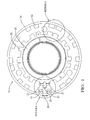
- Fig. 1 is a top plan view of an exemplary embodiment of a magnetic actuator having a unique tooth design
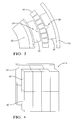
- Fig. 2 is a top plan view of another embodiment of a magnetic actuator
- Fig. 3 is a top plan view of one tooth deign of the magnetic actuator shown in Fig. 2 ;
- Fig. 4 is a perspective view of a section of the magnetic actuator illustrating a design of the actuator's magnets.
- Electromagnetic actuators for use in power steering systems such as variable effort steering (VES) systems are disclosed. It its contemplated that the magnetic actuators could be used in other applications as well such as torque overlay, park assist, lane maintaining, lead pull compensation, vehicle stability, and torque nudge.
- the magnetic actuators are designed to improve their robustness and efficiency in achieving a desired torque by optimizing the use of the magnets therein.
- the electromagnetic actuators are very compact and smaller in size than current electromagnetic actuators.
- the magnetic actuators can be manufactured fairly easily. This ease of manufacture combined with the small size of the actuators make them less expensive to manufacture.
- Fig. 1 illustrates an exemplary embodiment of a magnetic actuator 10.
- the actuator 10 includes a magnetic ring (shown later) interposed between an inner ring 20 and an outer ring 30.
- Inner pole teeth 22 are arranged in groups of two radially about the outer circumference of inner ring 20.
- the groups of inner pole teeth 22 are distributed equidistantly and symmetrically around inner ring 20.
- the inner pole teeth 22 extend in an outward direction toward outer ring 30.
- outer pole teeth 32 are arranged in groups of two radially about the inner circumference of outer ring 30.
- the outer pole teeth 32 extend in an inward direction toward inner ring 20.
- the outer pole teeth 32 are equidistantly distributed around outer ring 32 such that they are aligned to inner pole teeth 22.
- the inner and outer pole teeth 22, 32 are all the same height, which contributes to the ease with which they are manufactured. However, the inner pole teeth 22 and the outer pole teeth 32 have different widths. In the embodiment shown in Fig. 1 , the outer pole teeth 32 are wider than the inner pole teeth 22. The dimension of the width of the outer pole teeth 32 is shown as dimension 31 while the dimension of the width of the inner pole teeth 22 is shown as dimension 21. It is contemplated that the total number of teeth and the number in each group of inner and outer pole teeth 22, 32 could vary depending on the design parameters of the magnetic actuator 10.
- the inner ring 20, the outer ring 30, the inner pole teeth 22, and the outer pole teeth 32 arranged thereon include a magnetic material suitable for conducting magnetic flux upon application of an electric current.
- magnetic materials include but are not limited to soft magnetic steel, powdered metals, laminated silicon, or combinations comprising at least one of the foregoing materials.
- Current flows through an excitation coil (not shown) when it is desirable to create a magnetic field.
- Fig. 1 illustrates one exemplary embodiment in which design 1 includes an angular spacing 23 and 33 between two teeth that is larger in size than the angular spacing between the two teeth in design 2. This angular spacing may be varied to satisfy a desired designed torque specification.
- the teeth arranged according to design 2 can instead be arranged in accordance with design 3.
- This particular tooth design includes a single tooth having a dummy groove or notch near the middle of its upper surface. This tooth design is useful when the diameter of the magnetic actuator is decreased to a dimension so small that including angular spacing between the teeth in design 2 becomes impractical. Tooth design 3 is more clearly illustrated in Figs. 2 and 3 . As shown, a groove 24 is formed in the outer surface of each inner pole tooth 22, and a groove 34 is formed in the inner surface of each outer pole tooth 32. Figs. 2 and 3 also show the magnetic ring 40 as it is positioned between inner pole teeth 22 and outer pole teeth 32.
- the grooves 24 and 34 can vary in size and in shape. For example, they can be U-shaped as shown or semi-circular shaped.
- the outer groove 34 is shown as being larger than the inner groove 24; however, it is understood that the grooves could also be very similar in size.
- the magnetic ring 40 is defined herein as a ring made of a single annular magnet or as a ring made of several discrete magnets arranged radially around the inner ring 20.
- the discrete magnets are arc or flat shaped (e.g., rectangular, square, etc.).
- the magnetic ring 40 includes a permanent magnetic material.
- a "permanent" magnetic material exhibits magnetism even when no electrical current is applied. Examples of suitable permanent magnetic materials include but are not limited to alloys such as NdFeB, SmCo, and AlNiCo, composite materials such as AlNiCo in a plastic, and combinations comprising at least one of the foregoing materials.
- the magnetic ring 40 includes an upper set of magnets 50 and a lower set of magnets 60.
- the particular arrangement of the magnets are used in conjunction with the tooth designs described above to achieve a desired torque.
- the magnets are distributed in pole pairs symmetrically. Different pole pairs alternate around the top row of magnetic ring 40 that are offset from similar pole pairs in the bottom row.
- the ratio of the number of teeth in each ring to the number of magnetic poles in each row is a predetermined definite amount.
- the tooth to pole ratio can be about 1.
- the upper magnets 50 are different in width from the lower magnets 60.
- magnet configuration described herein is not intended to be limiting, for other designs of the magnet poles are contemplated.
- the magnets could be arranged in groups of more than two or as separate magnets not in groups.
Landscapes
- Engineering & Computer Science (AREA)
- Chemical & Material Sciences (AREA)
- Combustion & Propulsion (AREA)
- Transportation (AREA)
- Mechanical Engineering (AREA)
- Power Steering Mechanism (AREA)
Abstract
Description
- This application relates to power steering systems, and more particularly, to magnetic actuators for use with variable effort power steering systems.
- For example, power steering systems in motor vehicles, etc. are designed to provide appropriate hydraulic or electrical assist to allow a driver to complete a turn of the motor vehicle. The driver applies a steering input through a steering wheel that is rotationally connected to a first shaft. The first shaft is rotationally coupled to a second shaft that is, in turn, connected to a steering mechanism. The first and second shafts are torque transmittingly coupled together by a compliant member, such as a torsion bar. The torsion bar allows the first shaft to rotate with respect to the second shaft by a predetermined number of degrees, e.g., +/-12 degrees. Mechanical stops prevent further movement. The amount of steering assist applied to the steering mechanism is determined as a function of the degree of torsional strain or movement in the torsion bar.
- An exemplary power steering system is a hydraulic variable effort steering device having a proportional control valve and a magnetic actuator for varying the effective compliance of the torsion bar. The proportional control valve includes a valve spool connected to a manual steering wheel, a valve body connected to wheels of the vehicle, and a torsion bar between the valve spool and the valve body. Throttling orifices are positioned between the valve body and the valve spool to regulate a steering assist boost pressure when the valve spool is rotated relative to the valve body from the center position by manual effort at the steering wheel. As a result, a centering torque in the torsion bar is induced to effect a tactile response for the driver in the steering wheel. The magnetic actuator includes permanent magnets arranged around a ring that is attached to the valve spool. It also includes a pole piece attached to the valve body having outer pole teeth outside of the magnetic ring, inner pole teeth inside of the magnetic ring, and an exciting coil magnetically coupled to the pole teeth. The inner teeth and outer teeth are connected by a non-magnetic portion so that the inner teeth and outer teeth are magnetically decoupled. A current can be applied to the exciting coil to induce an electromagnetic torque between the pole piece and the permanent magnetic ring and thus increase or decrease the effective torque of the torsion bar depending on the direction of the current flowing through the coil.
- The arrangement and shape of the teeth in current magnetic actuators are often altered to achieve a desired torque. The teeth in current magnetic actuators are arranged in groups. In some cases, the teeth in each group are profiled differently, the inner teeth and the outer teeth are mis-aligned, and/or the arrangement of the groups of teeth around the magnetic ring is asymmetrical. Additionally, the magnetic actuators are often larger in size than desired due to magnet utilization being poor. As a result of these design specifications, current magnetic actuators can be difficult and expensive to manufacture.
- It is therefore desirable to develop an improved magnetic actuator that is smaller in size and easier to manufacture.
- Magnetic actuators for use in power steering systems are described herein. According to an embodiment, a magnetic actuator, comprising, an inner ring, an outer ring disposed around the inner ring, a first pair of inner teeth disposed on the inner ring that partially define a gap between the first pair of inner teeth having a first angular dimension, a second pair of inner teeth disposed on the inner ring that partially define a gap between the second pair of inner teeth having a second angular dimension, a first pair of outer teeth disposed on the outer ring that partially define a gap between the first pair of outer teeth having a third angular dimension and a second pair of outer teeth disposed on the outer ring that partially define a gap between the second pair of outer teeth having a fourth angular dimension.
- According to an alternate embodiment, a magnetic actuator, comprising, an inner ring, an outer ring disposed around the inner ring, a first pair of inner teeth disposed on the inner ring that partially define a gap between the first pair of inner teeth having a first angular dimension, a third tooth disposed on the inner ring that includes a first notch partially defined by the third tooth, a first pair of outer teeth disposed on the outer ring that partially define a gap between the first pair of outer teeth having a second angular dimension, and a fourth tooth disposed on the outer ring that includes a second notch partially defined by the fourth tooth.
- Referring now to the figures, which are meant to be exemplary, not limiting, and wherein the like elements are numbered alike:
-
Fig. 1 is a top plan view of an exemplary embodiment of a magnetic actuator having a unique tooth design; -
Fig. 2 is a top plan view of another embodiment of a magnetic actuator; -
Fig. 3 is a top plan view of one tooth deign of the magnetic actuator shown inFig. 2 ; and -
Fig. 4 is a perspective view of a section of the magnetic actuator illustrating a design of the actuator's magnets. - Electromagnetic actuators for use in power steering systems such as variable effort steering (VES) systems are disclosed. It its contemplated that the magnetic actuators could be used in other applications as well such as torque overlay, park assist, lane maintaining, lead pull compensation, vehicle stability, and torque nudge. The magnetic actuators are designed to improve their robustness and efficiency in achieving a desired torque by optimizing the use of the magnets therein. As such, the electromagnetic actuators are very compact and smaller in size than current electromagnetic actuators. Moreover, the magnetic actuators can be manufactured fairly easily. This ease of manufacture combined with the small size of the actuators make them less expensive to manufacture.
-
Fig. 1 illustrates an exemplary embodiment of amagnetic actuator 10. Theactuator 10 includes a magnetic ring (shown later) interposed between aninner ring 20 and anouter ring 30.Inner pole teeth 22 are arranged in groups of two radially about the outer circumference ofinner ring 20. The groups ofinner pole teeth 22 are distributed equidistantly and symmetrically aroundinner ring 20. Theinner pole teeth 22 extend in an outward direction towardouter ring 30. Additionally,outer pole teeth 32 are arranged in groups of two radially about the inner circumference ofouter ring 30. Theouter pole teeth 32 extend in an inward direction towardinner ring 20. Theouter pole teeth 32 are equidistantly distributed aroundouter ring 32 such that they are aligned toinner pole teeth 22. The inner andouter pole teeth inner pole teeth 22 and theouter pole teeth 32 have different widths. In the embodiment shown inFig. 1 , theouter pole teeth 32 are wider than theinner pole teeth 22. The dimension of the width of theouter pole teeth 32 is shown asdimension 31 while the dimension of the width of theinner pole teeth 22 is shown asdimension 21. It is contemplated that the total number of teeth and the number in each group of inner andouter pole teeth magnetic actuator 10. - The
inner ring 20, theouter ring 30, theinner pole teeth 22, and theouter pole teeth 32 arranged thereon include a magnetic material suitable for conducting magnetic flux upon application of an electric current. Examples of such magnetic materials include but are not limited to soft magnetic steel, powdered metals, laminated silicon, or combinations comprising at least one of the foregoing materials. Current flows through an excitation coil (not shown) when it is desirable to create a magnetic field. - As illustrated in
Fig. 1 , the aligned groups of inner andouter pole teeth magnetic actuator 10 are arranged in two different designs, i.e.,design 1 anddesign 2. It is understood that althoughFig. 1 depicts two design groups for the inner andouter pole teeth actuator 10 is not limited to only two designs groups and may have one design group or more than two design groups.Fig. 1 illustrates one exemplary embodiment in whichdesign 1 includes anangular spacing design 2. This angular spacing may be varied to satisfy a desired designed torque specification. - In an alternative embodiment depicted in
Fig. 2 , the teeth arranged according todesign 2 can instead be arranged in accordance withdesign 3. This particular tooth design includes a single tooth having a dummy groove or notch near the middle of its upper surface. This tooth design is useful when the diameter of the magnetic actuator is decreased to a dimension so small that including angular spacing between the teeth indesign 2 becomes impractical.Tooth design 3 is more clearly illustrated inFigs. 2 and3 . As shown, agroove 24 is formed in the outer surface of eachinner pole tooth 22, and agroove 34 is formed in the inner surface of eachouter pole tooth 32.Figs. 2 and3 also show themagnetic ring 40 as it is positioned betweeninner pole teeth 22 andouter pole teeth 32. Thegrooves outer groove 34 is shown as being larger than theinner groove 24; however, it is understood that the grooves could also be very similar in size. - The
magnetic ring 40 is defined herein as a ring made of a single annular magnet or as a ring made of several discrete magnets arranged radially around theinner ring 20. The discrete magnets are arc or flat shaped (e.g., rectangular, square, etc.). Themagnetic ring 40 includes a permanent magnetic material. A "permanent" magnetic material exhibits magnetism even when no electrical current is applied. Examples of suitable permanent magnetic materials include but are not limited to alloys such as NdFeB, SmCo, and AlNiCo, composite materials such as AlNiCo in a plastic, and combinations comprising at least one of the foregoing materials. - In another exemplary embodiment depicted in
Fig. 4 , themagnetic ring 40 includes an upper set ofmagnets 50 and a lower set ofmagnets 60. The particular arrangement of the magnets are used in conjunction with the tooth designs described above to achieve a desired torque. As shown, the magnets are distributed in pole pairs symmetrically. Different pole pairs alternate around the top row ofmagnetic ring 40 that are offset from similar pole pairs in the bottom row. The ratio of the number of teeth in each ring to the number of magnetic poles in each row is a predetermined definite amount. For example, the tooth to pole ratio can be about 1. In one embodiment, theupper magnets 50 are different in width from thelower magnets 60. It is understood that the magnet configuration described herein is not intended to be limiting, for other designs of the magnet poles are contemplated. For example, rather than being arranged in pairs, the magnets could be arranged in groups of more than two or as separate magnets not in groups. - As used herein, the terms "a" and "an" do not denote a limitation of quantity, but rather denote the presence of at least one of the referenced item. Reference throughout the specification to "one embodiment", "another embodiment", "an embodiment", and so forth means that a particular element (e.g., feature, structure, and/or characteristic) described in connection with the embodiment is included in at least one embodiment described herein, and may or may not be present in other embodiments. In addition, it is to be understood that the described elements may be combined in any suitable manner in the various embodiments. Unless defined otherwise, technical and scientific terms used herein have the same meaning as is commonly understood by one of skill in the art to which this invention belongs.
- While the present disclosure has been described with reference to the exemplary embodiments, it will be understood by those skilled in the art that various changes may be made and equivalents may be substituted for elements thereof without departing from the scope. In addition, many modifications may be made to adapt a particular situation or material to the teachings of the present disclosure without departing from the essential scope thereof. Therefore, it is intended that the present disclosure not be limited to the particular exemplary embodiments disclosed as the best mode contemplated for carrying out the exemplary embodiments.
Claims (10)
- A magnetic actuator, comprising:an inner ring (20);an outer ring (30) disposed around the inner ring (20);a first pair of inner teeth (21) disposed on the inner ring (20) that partially define a gap (23) between the first pair of inner teeth (21) having a first angular dimension;a second pair of inner teeth (Design 2) disposed on the inner ring (20) that partially define a gap (Design 2) between the second pair of inner teeth (Design 2) having a second angular dimension;a first pair of outer teeth (31) disposed on the outer ring (30) that partially define a gap (33) between the first pair of outer teeth (31) having a third angular dimension; anda second pair of outer teeth (Design 2) disposed on the outer ring (30) that partially define a gap between the second pair of outer teeth (Design 2) having a fourth angular dimension.
- The actuator of claim 1, wherein the second angular dimension is less than the first angular dimension.
- The actuator of claim 1, wherein the first pair of inner teeth (21) have a tooth width of a first dimension and the second pair of inner teeth (Design 2) have a tooth width of a second dimension.
- The actuator of claim 3, wherein the first dimension is less than the second dimension.
- The actuator of claim 1, wherein the actuator further comprises a magnetic ring (40) interposed between the inner ring and the outer ring.
- The actuator of claim 1, wherein the first pair of outer teeth (31) have a tooth width of a third dimension.
- The actuator of claim 1, wherein the second pair of outer teeth (Design 2) have a tooth width of a fourth dimension.
- The actuator of claim 1, wherein the third angular dimension is less than the fourth angular dimension.
- The actuator of claim 1, wherein the second angular dimension is greater than the first angular dimension.
- The actuator of claim 1, wherein the third angular dimension is greater than the fourth angular dimension.
Applications Claiming Priority (1)
| Application Number | Priority Date | Filing Date | Title |
|---|---|---|---|
| US95711407P | 2007-08-21 | 2007-08-21 |
Publications (3)
| Publication Number | Publication Date |
|---|---|
| EP2028081A2 true EP2028081A2 (en) | 2009-02-25 |
| EP2028081A3 EP2028081A3 (en) | 2009-11-25 |
| EP2028081B1 EP2028081B1 (en) | 2014-09-03 |
Family
ID=40028904
Family Applications (1)
| Application Number | Title | Priority Date | Filing Date |
|---|---|---|---|
| EP08161393.7A Active EP2028081B1 (en) | 2007-08-21 | 2008-07-29 | Variable effort steering actuator |
Country Status (3)
| Country | Link |
|---|---|
| US (1) | US7898139B2 (en) |
| EP (1) | EP2028081B1 (en) |
| CN (1) | CN101380967B (en) |
Cited By (1)
| Publication number | Priority date | Publication date | Assignee | Title |
|---|---|---|---|---|
| EP2767456A3 (en) * | 2013-02-13 | 2015-02-18 | Steering Solutions IP Holding Corporation | Hydraulic-power steering system with magnetic torque overlay |
Families Citing this family (5)
| Publication number | Priority date | Publication date | Assignee | Title |
|---|---|---|---|---|
| DE102014111624B4 (en) | 2013-08-15 | 2024-02-22 | Steering Solutions IP Holding Corp. | Assembly for providing steering assistance to a vehicle |
| US10160483B2 (en) | 2013-10-29 | 2018-12-25 | Steering Solutions Ip Holding Corporation | Retainer assembly for power steering system |
| CN106741161A (en) * | 2016-08-29 | 2017-05-31 | 佛山市帝盟汽车零部件有限公司 | A kind of many magnetic pole drive devices for being applied to automobile booster |
| US12344332B2 (en) | 2020-12-08 | 2025-07-01 | Ronald S. Bandy | Augmented rack and pinion steering system |
| US11772648B2 (en) | 2021-02-26 | 2023-10-03 | R.H. Sheppard Co. Inc. | Lane keep assistance based on rate of departure |
Citations (1)
| Publication number | Priority date | Publication date | Assignee | Title |
|---|---|---|---|---|
| US5454439A (en) | 1994-08-29 | 1995-10-03 | General Motors Corporation | Power steering gear for motor vehicle |
Family Cites Families (8)
| Publication number | Priority date | Publication date | Assignee | Title |
|---|---|---|---|---|
| NL58578C (en) * | 1938-07-19 | 1900-01-01 | ||
| US2837670A (en) * | 1954-08-05 | 1958-06-03 | Ind Controls Corp | Motors |
| US3602749A (en) * | 1970-02-20 | 1971-08-31 | Ernie B Esters | Dynamoelectric machine |
| US5119898A (en) * | 1989-08-10 | 1992-06-09 | General Motors Corporation | Electromagnetic control apparatus for varying the driver steering effort of a hydraulic power steering system |
| CN2406896Y (en) * | 2000-02-16 | 2000-11-22 | 荆州恒隆汽车零部件制造有限公司 | Two characteristic rotary valve for powered steering of vehicle |
| KR100388386B1 (en) * | 2000-11-28 | 2003-06-25 | 주식회사 만도 | Repelling power apparatus of a power steering system for a vehicle |
| US6597078B2 (en) * | 2000-12-04 | 2003-07-22 | Emerson Electric Co. | Electric power steering system including a permanent magnet motor |
| EP2006982B1 (en) * | 2007-06-21 | 2020-04-01 | GM Global Technology Operations LLC | Methods of making torque overlay actuators |
-
2008
- 2008-07-29 EP EP08161393.7A patent/EP2028081B1/en active Active
- 2008-08-07 US US12/187,722 patent/US7898139B2/en active Active
- 2008-08-21 CN CN200810168660.5A patent/CN101380967B/en active Active
Patent Citations (1)
| Publication number | Priority date | Publication date | Assignee | Title |
|---|---|---|---|---|
| US5454439A (en) | 1994-08-29 | 1995-10-03 | General Motors Corporation | Power steering gear for motor vehicle |
Cited By (1)
| Publication number | Priority date | Publication date | Assignee | Title |
|---|---|---|---|---|
| EP2767456A3 (en) * | 2013-02-13 | 2015-02-18 | Steering Solutions IP Holding Corporation | Hydraulic-power steering system with magnetic torque overlay |
Also Published As
| Publication number | Publication date |
|---|---|
| CN101380967A (en) | 2009-03-11 |
| CN101380967B (en) | 2013-03-13 |
| US20090050398A1 (en) | 2009-02-26 |
| US7898139B2 (en) | 2011-03-01 |
| EP2028081A3 (en) | 2009-11-25 |
| EP2028081B1 (en) | 2014-09-03 |
Similar Documents
| Publication | Publication Date | Title |
|---|---|---|
| EP2028081B1 (en) | Variable effort steering actuator | |
| DE60212406T2 (en) | Runners with embedded permanent magnets | |
| JP6218997B1 (en) | Rotating electric machine, electric power steering device, and method of manufacturing rotating electric machine | |
| EP1855371B1 (en) | Magnetic body, rotor, motor, compressor, fan, air conditioner, and on-vehicle air conditioner | |
| EP1359661A2 (en) | Brushless motor and electric power steering apparatus equipped with the brushless motor | |
| EP3166207A1 (en) | Electric power steering system | |
| CN104113178B (en) | Electric rotating machine | |
| JP6327456B2 (en) | Torque sensor and electric power steering device | |
| EP3268262B1 (en) | Dual rotor torque generating devices, systems, and methods | |
| CN103580336A (en) | Electric motor | |
| JP2017055493A (en) | Embedded magnet type rotor and manufacturing method of embedded magnet type rotor | |
| DE112007000289T5 (en) | Electric power steering device | |
| EP3012947A2 (en) | Method for manufacturing an interior permanent magnet rotor unit and magnetizing device | |
| US20080254901A1 (en) | Magnetic ring systems for attachment to a shaft and methods of making and using | |
| EP0816207A2 (en) | Power steering gear for motor vehicle | |
| US5454439A (en) | Power steering gear for motor vehicle | |
| JP3251933B2 (en) | Power steering device for vehicles | |
| JP6403672B2 (en) | Rotating electric machine and elevator hoisting machine | |
| CN102904413A (en) | Hybrid stepping motor | |
| EP2006982B1 (en) | Methods of making torque overlay actuators | |
| EP1768226A1 (en) | Electric motor and electric power steering device | |
| EP1209061A2 (en) | Repelling force apparatus for a power steering system of a vehicle | |
| JP2008211947A (en) | Radial anisotropic sintered magnet, method for manufacturing the same, brushless motor including the same, and electric power steering apparatus | |
| JPH0520624Y2 (en) | ||
| US5931195A (en) | Power steering apparatus for motor vehicle with two piece inner pole member and method for making the same |
Legal Events
| Date | Code | Title | Description |
|---|---|---|---|
| PUAI | Public reference made under article 153(3) epc to a published international application that has entered the european phase |
Free format text: ORIGINAL CODE: 0009012 |
|
| AK | Designated contracting states |
Kind code of ref document: A2 Designated state(s): AT BE BG CH CY CZ DE DK EE ES FI FR GB GR HR HU IE IS IT LI LT LU LV MC MT NL NO PL PT RO SE SI SK TR |
|
| AX | Request for extension of the european patent |
Extension state: AL BA MK RS |
|
| PUAL | Search report despatched |
Free format text: ORIGINAL CODE: 0009013 |
|
| AK | Designated contracting states |
Kind code of ref document: A3 Designated state(s): AT BE BG CH CY CZ DE DK EE ES FI FR GB GR HR HU IE IS IT LI LT LU LV MC MT NL NO PL PT RO SE SI SK TR |
|
| AX | Request for extension of the european patent |
Extension state: AL BA MK RS |
|
| 17P | Request for examination filed |
Effective date: 20100201 |
|
| 17Q | First examination report despatched |
Effective date: 20100311 |
|
| AKX | Designation fees paid |
Designated state(s): DE |
|
| RAP1 | Party data changed (applicant data changed or rights of an application transferred) |
Owner name: GM GLOBAL TECHNOLOGY OPERATIONS, INC. |
|
| RAP1 | Party data changed (applicant data changed or rights of an application transferred) |
Owner name: GM GLOBAL TECHNOLOGY OPERATIONS LLC |
|
| RAP1 | Party data changed (applicant data changed or rights of an application transferred) |
Owner name: GM GLOBAL TECHNOLOGY OPERATIONS LLC Owner name: STEERING SOLUTIONS IP HOLDING CORPORATION |
|
| GRAP | Despatch of communication of intention to grant a patent |
Free format text: ORIGINAL CODE: EPIDOSNIGR1 |
|
| INTG | Intention to grant announced |
Effective date: 20140219 |
|
| GRAS | Grant fee paid |
Free format text: ORIGINAL CODE: EPIDOSNIGR3 |
|
| GRAA | (expected) grant |
Free format text: ORIGINAL CODE: 0009210 |
|
| AK | Designated contracting states |
Kind code of ref document: B1 Designated state(s): DE |
|
| REG | Reference to a national code |
Ref country code: DE Ref legal event code: R096 Ref document number: 602008034184 Country of ref document: DE Effective date: 20141016 |
|
| REG | Reference to a national code |
Ref country code: DE Ref legal event code: R097 Ref document number: 602008034184 Country of ref document: DE |
|
| PLBE | No opposition filed within time limit |
Free format text: ORIGINAL CODE: 0009261 |
|
| STAA | Information on the status of an ep patent application or granted ep patent |
Free format text: STATUS: NO OPPOSITION FILED WITHIN TIME LIMIT |
|
| 26N | No opposition filed |
Effective date: 20150604 |
|
| PGFP | Annual fee paid to national office [announced via postgrant information from national office to epo] |
Ref country code: DE Payment date: 20250729 Year of fee payment: 18 |