EP2027833A1 - Trial prosthetic neck component - Google Patents
Trial prosthetic neck component Download PDFInfo
- Publication number
- EP2027833A1 EP2027833A1 EP08252772A EP08252772A EP2027833A1 EP 2027833 A1 EP2027833 A1 EP 2027833A1 EP 08252772 A EP08252772 A EP 08252772A EP 08252772 A EP08252772 A EP 08252772A EP 2027833 A1 EP2027833 A1 EP 2027833A1
- Authority
- EP
- European Patent Office
- Prior art keywords
- offset
- neck
- trial
- components
- component
- Prior art date
- Legal status (The legal status is an assumption and is not a legal conclusion. Google has not performed a legal analysis and makes no representation as to the accuracy of the status listed.)
- Granted
Links
- 241000469816 Varus Species 0.000 claims abstract description 20
- 241001227561 Valgus Species 0.000 claims abstract description 19
- 239000007943 implant Substances 0.000 claims abstract description 15
- 210000003739 neck Anatomy 0.000 claims description 143
- 206010061307 Neck deformity Diseases 0.000 claims description 8
- 239000004033 plastic Substances 0.000 claims description 6
- 229920003023 plastic Polymers 0.000 claims description 6
- 239000000463 material Substances 0.000 claims description 5
- 239000003086 colorant Substances 0.000 claims description 4
- 238000010276 construction Methods 0.000 claims description 4
- 230000003362 replicative effect Effects 0.000 claims description 4
- 230000001419 dependent effect Effects 0.000 claims 2
- 210000000689 upper leg Anatomy 0.000 description 4
- 210000000988 bone and bone Anatomy 0.000 description 3
- ACGUYXCXAPNIKK-UHFFFAOYSA-N hexachlorophene Chemical compound OC1=C(Cl)C=C(Cl)C(Cl)=C1CC1=C(O)C(Cl)=CC(Cl)=C1Cl ACGUYXCXAPNIKK-UHFFFAOYSA-N 0.000 description 2
- 210000002414 leg Anatomy 0.000 description 2
- 238000000034 method Methods 0.000 description 2
- 210000000588 acetabulum Anatomy 0.000 description 1
- 230000000694 effects Effects 0.000 description 1
- 210000002436 femur neck Anatomy 0.000 description 1
- 210000000527 greater trochanter Anatomy 0.000 description 1
- 210000001624 hip Anatomy 0.000 description 1
- 229910052588 hydroxylapatite Inorganic materials 0.000 description 1
- 238000002513 implantation Methods 0.000 description 1
- 238000003780 insertion Methods 0.000 description 1
- 230000037431 insertion Effects 0.000 description 1
- 238000007689 inspection Methods 0.000 description 1
- 239000002184 metal Substances 0.000 description 1
- XYJRXVWERLGGKC-UHFFFAOYSA-D pentacalcium;hydroxide;triphosphate Chemical compound [OH-].[Ca+2].[Ca+2].[Ca+2].[Ca+2].[Ca+2].[O-]P([O-])([O-])=O.[O-]P([O-])([O-])=O.[O-]P([O-])([O-])=O XYJRXVWERLGGKC-UHFFFAOYSA-D 0.000 description 1
- 210000004872 soft tissue Anatomy 0.000 description 1
- 238000001356 surgical procedure Methods 0.000 description 1
Images


Classifications
-
- A—HUMAN NECESSITIES
- A61—MEDICAL OR VETERINARY SCIENCE; HYGIENE
- A61F—FILTERS IMPLANTABLE INTO BLOOD VESSELS; PROSTHESES; DEVICES PROVIDING PATENCY TO, OR PREVENTING COLLAPSING OF, TUBULAR STRUCTURES OF THE BODY, e.g. STENTS; ORTHOPAEDIC, NURSING OR CONTRACEPTIVE DEVICES; FOMENTATION; TREATMENT OR PROTECTION OF EYES OR EARS; BANDAGES, DRESSINGS OR ABSORBENT PADS; FIRST-AID KITS
- A61F2/00—Filters implantable into blood vessels; Prostheses, i.e. artificial substitutes or replacements for parts of the body; Appliances for connecting them with the body; Devices providing patency to, or preventing collapsing of, tubular structures of the body, e.g. stents
- A61F2/02—Prostheses implantable into the body
- A61F2/30—Joints
- A61F2/46—Special tools for implanting artificial joints
- A61F2/4684—Trial or dummy prostheses
-
- A—HUMAN NECESSITIES
- A61—MEDICAL OR VETERINARY SCIENCE; HYGIENE
- A61B—DIAGNOSIS; SURGERY; IDENTIFICATION
- A61B17/00—Surgical instruments, devices or methods
- A61B17/16—Instruments for performing osteoclasis; Drills or chisels for bones; Trepans
- A61B17/1659—Surgical rasps, files, planes, or scrapers
-
- A—HUMAN NECESSITIES
- A61—MEDICAL OR VETERINARY SCIENCE; HYGIENE
- A61F—FILTERS IMPLANTABLE INTO BLOOD VESSELS; PROSTHESES; DEVICES PROVIDING PATENCY TO, OR PREVENTING COLLAPSING OF, TUBULAR STRUCTURES OF THE BODY, e.g. STENTS; ORTHOPAEDIC, NURSING OR CONTRACEPTIVE DEVICES; FOMENTATION; TREATMENT OR PROTECTION OF EYES OR EARS; BANDAGES, DRESSINGS OR ABSORBENT PADS; FIRST-AID KITS
- A61F2/00—Filters implantable into blood vessels; Prostheses, i.e. artificial substitutes or replacements for parts of the body; Appliances for connecting them with the body; Devices providing patency to, or preventing collapsing of, tubular structures of the body, e.g. stents
- A61F2/02—Prostheses implantable into the body
- A61F2/30—Joints
- A61F2002/30001—Additional features of subject-matter classified in A61F2/28, A61F2/30 and subgroups thereof
- A61F2002/30316—The prosthesis having different structural features at different locations within the same prosthesis; Connections between prosthetic parts; Special structural features of bone or joint prostheses not otherwise provided for
- A61F2002/30329—Connections or couplings between prosthetic parts, e.g. between modular parts; Connecting elements
- A61F2002/30331—Connections or couplings between prosthetic parts, e.g. between modular parts; Connecting elements made by longitudinally pushing a protrusion into a complementarily-shaped recess, e.g. held by friction fit
-
- A—HUMAN NECESSITIES
- A61—MEDICAL OR VETERINARY SCIENCE; HYGIENE
- A61F—FILTERS IMPLANTABLE INTO BLOOD VESSELS; PROSTHESES; DEVICES PROVIDING PATENCY TO, OR PREVENTING COLLAPSING OF, TUBULAR STRUCTURES OF THE BODY, e.g. STENTS; ORTHOPAEDIC, NURSING OR CONTRACEPTIVE DEVICES; FOMENTATION; TREATMENT OR PROTECTION OF EYES OR EARS; BANDAGES, DRESSINGS OR ABSORBENT PADS; FIRST-AID KITS
- A61F2/00—Filters implantable into blood vessels; Prostheses, i.e. artificial substitutes or replacements for parts of the body; Appliances for connecting them with the body; Devices providing patency to, or preventing collapsing of, tubular structures of the body, e.g. stents
- A61F2/02—Prostheses implantable into the body
- A61F2/30—Joints
- A61F2002/30001—Additional features of subject-matter classified in A61F2/28, A61F2/30 and subgroups thereof
- A61F2002/30316—The prosthesis having different structural features at different locations within the same prosthesis; Connections between prosthetic parts; Special structural features of bone or joint prostheses not otherwise provided for
- A61F2002/30329—Connections or couplings between prosthetic parts, e.g. between modular parts; Connecting elements
- A61F2002/30331—Connections or couplings between prosthetic parts, e.g. between modular parts; Connecting elements made by longitudinally pushing a protrusion into a complementarily-shaped recess, e.g. held by friction fit
- A61F2002/30362—Connections or couplings between prosthetic parts, e.g. between modular parts; Connecting elements made by longitudinally pushing a protrusion into a complementarily-shaped recess, e.g. held by friction fit with possibility of relative movement between the protrusion and the recess
- A61F2002/30364—Rotation about the common longitudinal axis
- A61F2002/30367—Rotation about the common longitudinal axis with additional means for preventing said rotation
-
- A—HUMAN NECESSITIES
- A61—MEDICAL OR VETERINARY SCIENCE; HYGIENE
- A61F—FILTERS IMPLANTABLE INTO BLOOD VESSELS; PROSTHESES; DEVICES PROVIDING PATENCY TO, OR PREVENTING COLLAPSING OF, TUBULAR STRUCTURES OF THE BODY, e.g. STENTS; ORTHOPAEDIC, NURSING OR CONTRACEPTIVE DEVICES; FOMENTATION; TREATMENT OR PROTECTION OF EYES OR EARS; BANDAGES, DRESSINGS OR ABSORBENT PADS; FIRST-AID KITS
- A61F2/00—Filters implantable into blood vessels; Prostheses, i.e. artificial substitutes or replacements for parts of the body; Appliances for connecting them with the body; Devices providing patency to, or preventing collapsing of, tubular structures of the body, e.g. stents
- A61F2/02—Prostheses implantable into the body
- A61F2/30—Joints
- A61F2002/30001—Additional features of subject-matter classified in A61F2/28, A61F2/30 and subgroups thereof
- A61F2002/30316—The prosthesis having different structural features at different locations within the same prosthesis; Connections between prosthetic parts; Special structural features of bone or joint prostheses not otherwise provided for
- A61F2002/30535—Special structural features of bone or joint prostheses not otherwise provided for
- A61F2002/30604—Special structural features of bone or joint prostheses not otherwise provided for modular
- A61F2002/30616—Sets comprising a plurality of prosthetic parts of different sizes or orientations
-
- A—HUMAN NECESSITIES
- A61—MEDICAL OR VETERINARY SCIENCE; HYGIENE
- A61F—FILTERS IMPLANTABLE INTO BLOOD VESSELS; PROSTHESES; DEVICES PROVIDING PATENCY TO, OR PREVENTING COLLAPSING OF, TUBULAR STRUCTURES OF THE BODY, e.g. STENTS; ORTHOPAEDIC, NURSING OR CONTRACEPTIVE DEVICES; FOMENTATION; TREATMENT OR PROTECTION OF EYES OR EARS; BANDAGES, DRESSINGS OR ABSORBENT PADS; FIRST-AID KITS
- A61F2/00—Filters implantable into blood vessels; Prostheses, i.e. artificial substitutes or replacements for parts of the body; Appliances for connecting them with the body; Devices providing patency to, or preventing collapsing of, tubular structures of the body, e.g. stents
- A61F2/02—Prostheses implantable into the body
- A61F2/30—Joints
- A61F2002/30001—Additional features of subject-matter classified in A61F2/28, A61F2/30 and subgroups thereof
- A61F2002/30316—The prosthesis having different structural features at different locations within the same prosthesis; Connections between prosthetic parts; Special structural features of bone or joint prostheses not otherwise provided for
- A61F2002/30535—Special structural features of bone or joint prostheses not otherwise provided for
- A61F2002/30617—Visible markings for adjusting, locating or measuring
-
- A—HUMAN NECESSITIES
- A61—MEDICAL OR VETERINARY SCIENCE; HYGIENE
- A61F—FILTERS IMPLANTABLE INTO BLOOD VESSELS; PROSTHESES; DEVICES PROVIDING PATENCY TO, OR PREVENTING COLLAPSING OF, TUBULAR STRUCTURES OF THE BODY, e.g. STENTS; ORTHOPAEDIC, NURSING OR CONTRACEPTIVE DEVICES; FOMENTATION; TREATMENT OR PROTECTION OF EYES OR EARS; BANDAGES, DRESSINGS OR ABSORBENT PADS; FIRST-AID KITS
- A61F2/00—Filters implantable into blood vessels; Prostheses, i.e. artificial substitutes or replacements for parts of the body; Appliances for connecting them with the body; Devices providing patency to, or preventing collapsing of, tubular structures of the body, e.g. stents
- A61F2/02—Prostheses implantable into the body
- A61F2/30—Joints
- A61F2002/30001—Additional features of subject-matter classified in A61F2/28, A61F2/30 and subgroups thereof
- A61F2002/30667—Features concerning an interaction with the environment or a particular use of the prosthesis
- A61F2002/3071—Identification means; Administration of patients
-
- A—HUMAN NECESSITIES
- A61—MEDICAL OR VETERINARY SCIENCE; HYGIENE
- A61F—FILTERS IMPLANTABLE INTO BLOOD VESSELS; PROSTHESES; DEVICES PROVIDING PATENCY TO, OR PREVENTING COLLAPSING OF, TUBULAR STRUCTURES OF THE BODY, e.g. STENTS; ORTHOPAEDIC, NURSING OR CONTRACEPTIVE DEVICES; FOMENTATION; TREATMENT OR PROTECTION OF EYES OR EARS; BANDAGES, DRESSINGS OR ABSORBENT PADS; FIRST-AID KITS
- A61F2/00—Filters implantable into blood vessels; Prostheses, i.e. artificial substitutes or replacements for parts of the body; Appliances for connecting them with the body; Devices providing patency to, or preventing collapsing of, tubular structures of the body, e.g. stents
- A61F2/02—Prostheses implantable into the body
- A61F2/30—Joints
- A61F2/32—Joints for the hip
- A61F2/36—Femoral heads ; Femoral endoprostheses
- A61F2/3609—Femoral heads or necks; Connections of endoprosthetic heads or necks to endoprosthetic femoral shafts
- A61F2002/3611—Heads or epiphyseal parts of femur
-
- A—HUMAN NECESSITIES
- A61—MEDICAL OR VETERINARY SCIENCE; HYGIENE
- A61F—FILTERS IMPLANTABLE INTO BLOOD VESSELS; PROSTHESES; DEVICES PROVIDING PATENCY TO, OR PREVENTING COLLAPSING OF, TUBULAR STRUCTURES OF THE BODY, e.g. STENTS; ORTHOPAEDIC, NURSING OR CONTRACEPTIVE DEVICES; FOMENTATION; TREATMENT OR PROTECTION OF EYES OR EARS; BANDAGES, DRESSINGS OR ABSORBENT PADS; FIRST-AID KITS
- A61F2/00—Filters implantable into blood vessels; Prostheses, i.e. artificial substitutes or replacements for parts of the body; Appliances for connecting them with the body; Devices providing patency to, or preventing collapsing of, tubular structures of the body, e.g. stents
- A61F2/02—Prostheses implantable into the body
- A61F2/30—Joints
- A61F2/32—Joints for the hip
- A61F2/36—Femoral heads ; Femoral endoprostheses
- A61F2/3609—Femoral heads or necks; Connections of endoprosthetic heads or necks to endoprosthetic femoral shafts
- A61F2002/3625—Necks
-
- A—HUMAN NECESSITIES
- A61—MEDICAL OR VETERINARY SCIENCE; HYGIENE
- A61F—FILTERS IMPLANTABLE INTO BLOOD VESSELS; PROSTHESES; DEVICES PROVIDING PATENCY TO, OR PREVENTING COLLAPSING OF, TUBULAR STRUCTURES OF THE BODY, e.g. STENTS; ORTHOPAEDIC, NURSING OR CONTRACEPTIVE DEVICES; FOMENTATION; TREATMENT OR PROTECTION OF EYES OR EARS; BANDAGES, DRESSINGS OR ABSORBENT PADS; FIRST-AID KITS
- A61F2/00—Filters implantable into blood vessels; Prostheses, i.e. artificial substitutes or replacements for parts of the body; Appliances for connecting them with the body; Devices providing patency to, or preventing collapsing of, tubular structures of the body, e.g. stents
- A61F2/02—Prostheses implantable into the body
- A61F2/30—Joints
- A61F2/32—Joints for the hip
- A61F2/36—Femoral heads ; Femoral endoprostheses
- A61F2/3609—Femoral heads or necks; Connections of endoprosthetic heads or necks to endoprosthetic femoral shafts
- A61F2002/3652—Connections of necks to shafts
-
- A—HUMAN NECESSITIES
- A61—MEDICAL OR VETERINARY SCIENCE; HYGIENE
- A61F—FILTERS IMPLANTABLE INTO BLOOD VESSELS; PROSTHESES; DEVICES PROVIDING PATENCY TO, OR PREVENTING COLLAPSING OF, TUBULAR STRUCTURES OF THE BODY, e.g. STENTS; ORTHOPAEDIC, NURSING OR CONTRACEPTIVE DEVICES; FOMENTATION; TREATMENT OR PROTECTION OF EYES OR EARS; BANDAGES, DRESSINGS OR ABSORBENT PADS; FIRST-AID KITS
- A61F2220/00—Fixations or connections for prostheses classified in groups A61F2/00 - A61F2/26 or A61F2/82 or A61F9/00 or A61F11/00 or subgroups thereof
- A61F2220/0025—Connections or couplings between prosthetic parts, e.g. between modular parts; Connecting elements
- A61F2220/0033—Connections or couplings between prosthetic parts, e.g. between modular parts; Connecting elements made by longitudinally pushing a protrusion into a complementary-shaped recess, e.g. held by friction fit
-
- A—HUMAN NECESSITIES
- A61—MEDICAL OR VETERINARY SCIENCE; HYGIENE
- A61F—FILTERS IMPLANTABLE INTO BLOOD VESSELS; PROSTHESES; DEVICES PROVIDING PATENCY TO, OR PREVENTING COLLAPSING OF, TUBULAR STRUCTURES OF THE BODY, e.g. STENTS; ORTHOPAEDIC, NURSING OR CONTRACEPTIVE DEVICES; FOMENTATION; TREATMENT OR PROTECTION OF EYES OR EARS; BANDAGES, DRESSINGS OR ABSORBENT PADS; FIRST-AID KITS
- A61F2250/00—Special features of prostheses classified in groups A61F2/00 - A61F2/26 or A61F2/82 or A61F9/00 or A61F11/00 or subgroups thereof
- A61F2250/0058—Additional features; Implant or prostheses properties not otherwise provided for
- A61F2250/0085—Identification means; Administration of patients
-
- A—HUMAN NECESSITIES
- A61—MEDICAL OR VETERINARY SCIENCE; HYGIENE
- A61F—FILTERS IMPLANTABLE INTO BLOOD VESSELS; PROSTHESES; DEVICES PROVIDING PATENCY TO, OR PREVENTING COLLAPSING OF, TUBULAR STRUCTURES OF THE BODY, e.g. STENTS; ORTHOPAEDIC, NURSING OR CONTRACEPTIVE DEVICES; FOMENTATION; TREATMENT OR PROTECTION OF EYES OR EARS; BANDAGES, DRESSINGS OR ABSORBENT PADS; FIRST-AID KITS
- A61F2250/00—Special features of prostheses classified in groups A61F2/00 - A61F2/26 or A61F2/82 or A61F9/00 or A61F11/00 or subgroups thereof
- A61F2250/0058—Additional features; Implant or prostheses properties not otherwise provided for
- A61F2250/0085—Identification means; Administration of patients
- A61F2250/0087—Identification means; Administration of patients colour-coded
-
- A—HUMAN NECESSITIES
- A61—MEDICAL OR VETERINARY SCIENCE; HYGIENE
- A61F—FILTERS IMPLANTABLE INTO BLOOD VESSELS; PROSTHESES; DEVICES PROVIDING PATENCY TO, OR PREVENTING COLLAPSING OF, TUBULAR STRUCTURES OF THE BODY, e.g. STENTS; ORTHOPAEDIC, NURSING OR CONTRACEPTIVE DEVICES; FOMENTATION; TREATMENT OR PROTECTION OF EYES OR EARS; BANDAGES, DRESSINGS OR ABSORBENT PADS; FIRST-AID KITS
- A61F2250/00—Special features of prostheses classified in groups A61F2/00 - A61F2/26 or A61F2/82 or A61F9/00 or A61F11/00 or subgroups thereof
- A61F2250/0058—Additional features; Implant or prostheses properties not otherwise provided for
- A61F2250/0096—Markers and sensors for detecting a position or changes of a position of an implant, e.g. RF sensors, ultrasound markers
- A61F2250/0097—Visible markings, e.g. indicia
Definitions
- This invention relates to a trial prosthetic neck component which is adapted for use with a trial femoral stem or broach or an implanted femoral stem.
- the trial prosthetic neck component is intended for use in a modular operative technique before fitting a femoral implant which employs a modular prosthetic neck component the distal end of which is attached to a femoral stem and the proximal end of which carries or is attached to a bearing head in the shape of a part-spherical ball.
- the use of the modular neck component enables the surgeon to provide any required offset to suit the joint at the time of implantation.
- a trial prosthetic neck component adapted for use with a trial femoral stem or broach, or an implanted femoral stem, has connection means for removably connecting it at its distal end to said trial femoral stem or broach, or an implanted femoral stem, and connection means at its proximal end for connection to a bearing head, and in which said proximal end is provided with indicea to indicate its length and any valgus, varus, anteverted, retroverted offset.
- a number of trial neck components can be provided and the operating surgeon can select an appropriate trial neck having the necessary offset and length to suit the patient. He can assess the neck component when fitted or carrying the bearing head and by selecting the appropriate component achieve the desired result for a good fit.
- the indicea provided on the end of the component enables the surgeon to then select the appropriate modular neck component from a supply and will enable the surgeon to build up the implant as required.
- the indicea indicating offset comprises a line extending in the direction of the offset.
- the indicea which indicates the length of the component can be provided by a coloured dot the longer the length the greater the diameter of the dot.
- Each line indicating the offset preferably extends outwardly from the length indicating dot provided at a central point on the proximal end of the neck component. The line thus points in the direction of the offset and extends away from the length indicating dot.
- connection means which allows removable connection of the neck component to the trial stem or broach or the actual stem may include a cylindrical plug and an angularly located socket.
- said cylindrical plug and angularly located socket can be adapted to engage and fit an existing socket and projecting abutment on said broach
- the connecting means also includes a connector the proximal end of which has a socket and projecting abutment to engage the plug and socket on the neck component and the distal end of which has a spade connector to engage and locate in the trial stem or implanted femoral stem.
- the proximal end of the connector may include a plug and an angularly located socket and the distal end of the neck component can have a socket to receive said plug and a projecting abutment to engage the angularly located socket.
- the connector can be made of a synthetic plastics material.
- the trial prosthetic neck component can be provided in combination with a number of other similar trial neck components which have different lengths and/or offsets and which can be selectively connected to a trial medullary stem or broach or an implanted femoral stem and a bearing head to provide a modular construction of trial femoral implants of different lengths and offsets so that a surgeon can achieve the desired length and offset of either a trial implant provided by a trial stem or a broach or by fitting the trial neck component to a femoral stem which has already been implanted.
- the trial prosthetic neck component can therefore be provided in combination with seventeen similar trial neck components, nine of the components having long necks, three of said long neck components having a valgus offset and one of which also has an anteverted offset, another of which also has a retroverted offset and a third of which has no anteverted or retroverted offset; another three of said long neck components having a varus offset one of which also has an anteverted offset another of which also has a retroverted offset and a third of which has no anteverted or retroverted offset; and the remaining three of said long neck components having no valgus or varus offset, one of said three having an anteverted offset, another having a retroverted offset and a third of which has no anteverted or retroverted offset; the remaining nine neck components having short necks and replicating the various offsets of the nine long neck components.
- the operating surgeon is able to choose a trial neck component which is of long or short neck length and which has offsets in all the available directions.
- the indicea on the proximal end of the component which he/she has selected enables him/her to then take the appropriate modular component which is to be secured to the stem.
- each of the nine long neck trial components carries a coloured dot to indicate the particular offset
- each two components have offsets which are the reciprocal of each other and one of which has a valgus effect and the other a varus offset having the same colour, and the components which do not have a valgus or varus offset having the same colour; and the nine neck components having short necks and replicating the various offsets of the nine long neck components having a similar colour coding.
- the coloured dot which indicates the length of the component can also carry the colour coding which indicates the offset.
- Suitable colours are brown, green, blue, yellow and grey.
- This arrangement enables the use of only ten modular necks for use in the implanted stem. Because they can be constructed so that in each of the constructions they can be used in the reciprocal directions merely by rotating them through 180°, thus a neck which has a varus anteverted offset can also be used by rotating it through 180° as a neck valgus and retroverted offset.
- the modular necks which are to be inserted in the fixed stem also, preferably, carry the colour coding of the test necks so that if, for example, the colour of the neck which had varus and anteverted offset is yellow and can be used with an implanted stem could be used by the surgeon but he could also use the same yellow neck if the test neck indicated that an offset of varus retroverted was required merely by rotating the modular stem to the appropriate direction.
- Modular necks could also carry the direction indicators as used by the test necks to enable this to be done.
- the invention also includes a trial prosthetic neck component as set forth above in combination with seventeen similar trial neck components which have the colour coding and offset indicea form part of a kit of parts which also includes ten modular necks of different offsets which can be used when the required offset has been determined by the trial offset necks and one or more modular stems which were used to replace the trial broach or stem, together with one or more trial broaches or stems.
- the kit of parts could also include one or more bearing heads attachable to the appropriate modular neck or the modular necks could carry integral bearing heads.
- the spade is provided on the distal end of the connector.
- a similar spade-shape connector is provided on the modular necks but in this case are a tight or interference fit whereas the spade on the connector which is preferably made of a synthetic plastics material is a tight or push fit into the slot.
- Figure 1 is a diagrammatic illustration of the proximal end of a femur 1 which is resected at 2 to provide a flat planar surface 3 in which a femoral prosthesis 4 has been implanted.
- the prosthesis 4 is of modular construction and comprises a stem 5 located in the femur, a modular neck 6, the distal end of which is secured to the stem 5 and the proximal end of which is provided with a conical boss 7 which has a Morse taper and on which a spherical or part-spherical bearing head can be mounted.
- the distal end of the modular neck 6 is provided with an engagement spade 10 which is shaped to locate in an elongated slot 11 which is most clearly shown in Figure 6 .
- the engagement spade 10 is dimensioned to be pushed or driven into the elongate by providing a tight or interference fit.
- Spade 10 may have curved ends connected by straight portions.
- the modular femoral stem 5 can be made in left or right-handed versions.
- Figure 7 shows the proximal end of a broach 70 which can be used with the present invention and which has connection means 71 which include a flange 72 which has a central plug 75 and an angularly located socket 74 to receive a handle or other equipment.
- the present invention therefore, provides a trial prosthetic neck component which can be used with a trial femoral stem or broach, if suitable, or with an already implanted modular femoral stem.
- the trial prosthetic neck component is shown in Figure 3 and comprises a shaped neck 12, the proximal end of which carries a tapered engagement boss 13 for a spherical bearing head (not shown) and the distal end of which has connection means 14 for removably connecting it to the proximal end of the trial femoral stem or broach or the implanted stem.
- the trial stem can be basically similar to the stem 5 of the implanted prosthesis or it can be in the form of a broach as shown in Figure 7 which has been used to define the opening in the bone.
- the broach is left in position and used as a trial stem. If a trial stem is used it is provided with an elongated slot similar to that shown in Figure 6 to receive the trial neck.
- the connection means are therefore provided with a connector 15 which has a distal spade-shaped end 16 similar to the shape-shaped end 10 of the modular neck 6.
- the spade end extends from a flange 17 which has a central plug 18 and an angularly located socket 19.
- the distal end of the neck component 12 has a socket 20 to receive the plug 18 and a projecting abutment 21 to engage the angularly located socket 19.
- the connector can be made from a synthetic plastics material so that when it is assembled to the trial neck the plug 18 is a tight push fit into the socket 19 and the abutment 21 is a tight fit in the socket 19 so that the connector is firmly held in position. If the broach 70 is used for trials then the socket 20 and projecting abutment 21 can be used to engage the central plug 73 and socket 74, and the connected 15 is not required.
- Figure 4 illustrates eighteen modular trial necks of the kind shown in Figure 3 .
- the rear row of components all have long necks.
- the left hand group of three of these long-necked components and indicated by reference numeral 30 have valgus offset, one of which indicated by reference numeral 31 also has an anteverted offset and that indicated by reference numeral 32 has a retroverted offset and that indicated by reference numeral 33 has no antevrted or retroverted offset.
- the remaining three of said long neck components and indicated by reference numeral 40 have no valgus or varus offset, one of the said three, indicated by reference numeral 41, has an anteverted offsest, another indicated by reference numeral 42, has a retroverted offset and the third, indicated by reference numeral 43, has no anteverted or retroverted offset .
- trial neck components shown in the front row in Figure 4 are similar to those shown in the back row and indicated by reference numerals 30 to 43 but all the front row components have a short neck.
- the two lengths of neck and various offsets enable the surgeon to assemble the required length and offset but once he has selected the trial neck he requires he has to identify that neck with the modular necks which are to be used in the implant, and in order to assist the surgeon the proximal end faces of the trial necks carry indicea to indicate its length and any valgus, varus, anteverted, reverted offset.
- Figure 5 shows how the indicea is applied.
- the indicea indicating offset comprises a line extending in the direction of the offset.
- the indicea which indicates the length of the component is provided by a coloured dot, the longer the length of the component the greater the diameter of the dot.
- Each line indicating the offset extends outwardly from the length indicated dot which is provided as a central point on the proximal end of the neck component.
- the indicating lines 52 can extend in various directions according to their requirement, for example, a large central dot 50 indicates a long neck whereas a smaller dot (indicated by reference numeral 51) will indicate a short neck. No line associated to the dot indicates that the neck is neither varus nor valgus and neither anteverted nor retroverted.
- a horizontal line, such as indicated by reference numeral 55 indicates an anteverted neck and a horizontal line, as indicated by reference numeral 56, indicates a retroverted neck.
- a horizontal and vertical line such as shown at reference numeral 57 indicates a valgus neck which is anteverted.
- necks will be available to the surgeon, five of long length and five of short. As the spade stem 10 of the modular necks can be rotated through 180° only five of said necks of each length would be necessary. In order to identify the necks the coloured dots and lines are of different colours. As shown in Figure 5 those necks which have offsets which are the reciprocal of each other carry the same colour. Thus, neck 60 with a large dot 50 carries the same colour (yellow) as the head 61 which is its reciprocal when rotated through 180°. Head 62 is the reciprocal of head 63 and thus carries the same colour (green).
- Head 64 is the reciprocal of head 65 and carries the same colour (blue)
- head 66 is the reciprocal of head 67 and again carries the same colour (brown).
- the remaining head which does not have any opposite (head 68) is colour grey.
- the same colour scheme is also applied to the short length necks.
- the surgeon will first resect the femoral neck until the metaphyseal housing of the implant is prepared.
- a hollow chisel is preferably used which is adapted to the size of the implant and fixed to a broach handle.
- a cylinder of cancellous bone is removed from the metaphysis taking care not to damage the calcar of the greater trochanter.
- the smallest broach, left or right, is then introduced into the final medullary canal.
- Flexible reamers can be used up to the diameter corresponding to the chosen implant. After checking that they correspond to the side being operated broaches are fixed to the broach handle and they are introduced beginning with the smaller size up the size chosen during pre-op planning.
- the broach and and/or a trial prosthesis size will determine the size of the permanent implant. If the broach is unstable then a larger broach may be necessary.
- a metal trial neck from the broach featuring the CCD angle and neck length chosen during pre-op templating, combined with a standard anteversion can be used first.
- the CCD angle on a neck length is selected by checking leg length and soft tissue tension and various head lengths can be used to enable fine tuning.
- the stem can have a small plastic stem holder at its proximal end to enable the surgeon to handle it without damage.
- the modular stem is now inserted with its spade end in the elongated opening 11 and hammered into position.
- the bearing head (not shown) can now be fitted.
- the invention provides a test neck which, when used, indicates to the surgeon the precise type of modular neck which can be used to obtain the desired results.
- the proximal ends of the trial stems can also carry other information, for example size, numbers and any other indicea which may be of use to the surgeon.
Landscapes
- Health & Medical Sciences (AREA)
- Transplantation (AREA)
- Orthopedic Medicine & Surgery (AREA)
- Heart & Thoracic Surgery (AREA)
- Life Sciences & Earth Sciences (AREA)
- Oral & Maxillofacial Surgery (AREA)
- Engineering & Computer Science (AREA)
- Biomedical Technology (AREA)
- Physical Education & Sports Medicine (AREA)
- Vascular Medicine (AREA)
- Cardiology (AREA)
- Animal Behavior & Ethology (AREA)
- General Health & Medical Sciences (AREA)
- Public Health (AREA)
- Veterinary Medicine (AREA)
- Prostheses (AREA)
- Surgical Instruments (AREA)
Abstract
Description
- This invention relates to a trial prosthetic neck component which is adapted for use with a trial femoral stem or broach or an implanted femoral stem.
- The trial prosthetic neck component, according to the invention, is intended for use in a modular operative technique before fitting a femoral implant which employs a modular prosthetic neck component the distal end of which is attached to a femoral stem and the proximal end of which carries or is attached to a bearing head in the shape of a part-spherical ball. The use of the modular neck component enables the surgeon to provide any required offset to suit the joint at the time of implantation.
- According to the present invention a trial prosthetic neck component adapted for use with a trial femoral stem or broach, or an implanted femoral stem, has connection means for removably connecting it at its distal end to said trial femoral stem or broach, or an implanted femoral stem, and connection means at its proximal end for connection to a bearing head, and in which said proximal end is provided with indicea to indicate its length and any valgus, varus, anteverted, retroverted offset.
- Thus, a number of trial neck components, as set out above, can be provided and the operating surgeon can select an appropriate trial neck having the necessary offset and length to suit the patient. He can assess the neck component when fitted or carrying the bearing head and by selecting the appropriate component achieve the desired result for a good fit. The indicea provided on the end of the component enables the surgeon to then select the appropriate modular neck component from a supply and will enable the surgeon to build up the implant as required.
- In a preferred embodiment the indicea indicating offset comprises a line extending in the direction of the offset.
- With this arrangement the indicea which indicates the length of the component can be provided by a coloured dot the longer the length the greater the diameter of the dot.
- Each line indicating the offset preferably extends outwardly from the length indicating dot provided at a central point on the proximal end of the neck component. The line thus points in the direction of the offset and extends away from the length indicating dot.
- The connection means which allows removable connection of the neck component to the trial stem or broach or the actual stem may include a cylindrical plug and an angularly located socket.
- With this arrangement said cylindrical plug and angularly located socket can be adapted to engage and fit an existing socket and projecting abutment on said broach, and the connecting means also includes a connector the proximal end of which has a socket and projecting abutment to engage the plug and socket on the neck component and the distal end of which has a spade connector to engage and locate in the trial stem or implanted femoral stem.
- With this arrangement the proximal end of the connector may include a plug and an angularly located socket and the distal end of the neck component can have a socket to receive said plug and a projecting abutment to engage the angularly located socket. This arrangement ensures that the connector is fixed against relative angular rotation to the stem when in position.
- In order to provide a connection which can be a tight push fit the connector can be made of a synthetic plastics material.
- The trial prosthetic neck component, according to the invention, can be provided in combination with a number of other similar trial neck components which have different lengths and/or offsets and which can be selectively connected to a trial medullary stem or broach or an implanted femoral stem and a bearing head to provide a modular construction of trial femoral implants of different lengths and offsets so that a surgeon can achieve the desired length and offset of either a trial implant provided by a trial stem or a broach or by fitting the trial neck component to a femoral stem which has already been implanted.
- The trial prosthetic neck component can therefore be provided in combination with seventeen similar trial neck components, nine of the components having long necks, three of said long neck components having a valgus offset and one of which also has an anteverted offset, another of which also has a retroverted offset and a third of which has no anteverted or retroverted offset; another three of said long neck components having a varus offset one of which also has an anteverted offset another of which also has a retroverted offset and a third of which has no anteverted or retroverted offset; and the remaining three of said long neck components having no valgus or varus offset, one of said three having an anteverted offset, another having a retroverted offset and a third of which has no anteverted or retroverted offset; the remaining nine neck components having short necks and replicating the various offsets of the nine long neck components.
- With this arrangement the operating surgeon is able to choose a trial neck component which is of long or short neck length and which has offsets in all the available directions. The indicea on the proximal end of the component which he/she has selected enables him/her to then take the appropriate modular component which is to be secured to the stem.
- In a preferred arrangement each of the nine long neck trial components carries a coloured dot to indicate the particular offset, each two components have offsets which are the reciprocal of each other and one of which has a valgus effect and the other a varus offset having the same colour, and the components which do not have a valgus or varus offset having the same colour; and the nine neck components having short necks and replicating the various offsets of the nine long neck components having a similar colour coding.
- The coloured dot which indicates the length of the component can also carry the colour coding which indicates the offset.
- Suitable colours are brown, green, blue, yellow and grey.
- This arrangement enables the use of only ten modular necks for use in the implanted stem. Because they can be constructed so that in each of the constructions they can be used in the reciprocal directions merely by rotating them through 180°, thus a neck which has a varus anteverted offset can also be used by rotating it through 180° as a neck valgus and retroverted offset.
- The modular necks which are to be inserted in the fixed stem also, preferably, carry the colour coding of the test necks so that if, for example, the colour of the neck which had varus and anteverted offset is yellow and can be used with an implanted stem could be used by the surgeon but he could also use the same yellow neck if the test neck indicated that an offset of varus retroverted was required merely by rotating the modular stem to the appropriate direction. Modular necks could also carry the direction indicators as used by the test necks to enable this to be done.
- The invention also includes a trial prosthetic neck component as set forth above in combination with seventeen similar trial neck components which have the colour coding and offset indicea form part of a kit of parts which also includes ten modular necks of different offsets which can be used when the required offset has been determined by the trial offset necks and one or more modular stems which were used to replace the trial broach or stem, together with one or more trial broaches or stems.
- The kit of parts could also include one or more bearing heads attachable to the appropriate modular neck or the modular necks could carry integral bearing heads.
- The spade is provided on the distal end of the connector. A similar spade-shape connector is provided on the modular necks but in this case are a tight or interference fit whereas the spade on the connector which is preferably made of a synthetic plastics material is a tight or push fit into the slot.
- The invention can be performed in various ways and one embodiment will now be described by way of example and with reference to the accompanying drawings in which :-
-
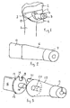
Figure 1 is a diagrammatic isometric view showing the proximal end of a femur the head of which has been resected to receive an implant having a stem located within the femur and projecting neck to which a bearing, in the form of a hemispherical ball can be fitted; -
Figure 2 is an isometric view of a modular neck similar to that shown inFigure 1 which can be located in an implanted stem; -
Figure 3 is a diagrammatic isometric view from one side of a trial prosthetic neck component, according to the invention; -
Figure 4 is an isometric view from the front of eighteen alternative trial neck components according to the invention; -
Figure 5 is a diagrammatic view of the proximal ends of the components shown inFigure 4 ; -
Figure 6 shows left and right handed prosthetic stems which can be used with the present invention; and, -
Figure 7 is a diagrammatic view of the proximal end of a broach with which the invention can be used. -
Figure 1 is a diagrammatic illustration of the proximal end of a femur 1 which is resected at 2 to provide a flatplanar surface 3 in which afemoral prosthesis 4 has been implanted. Theprosthesis 4 is of modular construction and comprises astem 5 located in the femur, amodular neck 6, the distal end of which is secured to thestem 5 and the proximal end of which is provided with a conical boss 7 which has a Morse taper and on which a spherical or part-spherical bearing head can be mounted. - As will be seen from
Figure 2 the distal end of themodular neck 6 is provided with an engagement spade 10 which is shaped to locate in an elongated slot 11 which is most clearly shown inFigure 6 . The engagement spade 10 is dimensioned to be pushed or driven into the elongate by providing a tight or interference fit. Spade 10 may have curved ends connected by straight portions. - As will be seen from
Figure 6 the modularfemoral stem 5 can be made in left or right-handed versions. -
Figure 7 shows the proximal end of abroach 70 which can be used with the present invention and which has connection means 71 which include aflange 72 which has a central plug 75 and an angularly locatedsocket 74 to receive a handle or other equipment. - Before fitting an implant of the type shown in
Figure 1 it is usual to provide a trial component to enable the surgeon to assess the necessary dimensions and consider whether there should be any degree of offset of the modular neck in relation to the stem. - The present invention, therefore, provides a trial prosthetic neck component which can be used with a trial femoral stem or broach, if suitable, or with an already implanted modular femoral stem. The trial prosthetic neck component is shown in
Figure 3 and comprises ashaped neck 12, the proximal end of which carries atapered engagement boss 13 for a spherical bearing head (not shown) and the distal end of which has connection means 14 for removably connecting it to the proximal end of the trial femoral stem or broach or the implanted stem. The trial stem can be basically similar to thestem 5 of the implanted prosthesis or it can be in the form of a broach as shown inFigure 7 which has been used to define the opening in the bone. The broach is left in position and used as a trial stem. If a trial stem is used it is provided with an elongated slot similar to that shown inFigure 6 to receive the trial neck. The connection means are therefore provided with aconnector 15 which has a distal spade-shaped end 16 similar to the shape-shaped end 10 of themodular neck 6. The spade end extends from aflange 17 which has a central plug 18 and an angularly located socket 19. The distal end of theneck component 12 has asocket 20 to receive the plug 18 and a projectingabutment 21 to engage the angularly located socket 19. The connector can be made from a synthetic plastics material so that when it is assembled to the trial neck the plug 18 is a tight push fit into the socket 19 and theabutment 21 is a tight fit in the socket 19 so that the connector is firmly held in position. If thebroach 70 is used for trials then thesocket 20 and projectingabutment 21 can be used to engage thecentral plug 73 andsocket 74, and the connected 15 is not required. - A number of trial necks are provided in different lengths and offsets so that the surgeon can select the trial neck which is appropriate for the patient.
Figure 4 illustrates eighteen modular trial necks of the kind shown inFigure 3 . InFigure 4 the rear row of components all have long necks. The left hand group of three of these long-necked components and indicated byreference numeral 30 have valgus offset, one of which indicated byreference numeral 31 also has an anteverted offset and that indicated byreference numeral 32 has a retroverted offset and that indicated byreference numeral 33 has no antevrted or retroverted offset. - In the next group of neck components, indicated by
reference numeral 35, in varus offset one of which indicated byreference numeral 36 has an anteverted offset, another, indicated byreference numeral 37, has a retroverted offset and the third, indicated byreference numeral 38 - The remaining three of said long neck components and indicated by
reference numeral 40 have no valgus or varus offset, one of the said three, indicated by reference numeral 41, has an anteverted offsest, another indicated byreference numeral 42, has a retroverted offset and the third, indicated byreference numeral 43, has no anteverted or retroverted offset . - The trial neck components shown in the front row in
Figure 4 are similar to those shown in the back row and indicated byreference numerals 30 to 43 but all the front row components have a short neck. - The two lengths of neck and various offsets enable the surgeon to assemble the required length and offset but once he has selected the trial neck he requires he has to identify that neck with the modular necks which are to be used in the implant, and in order to assist the surgeon the proximal end faces of the trial necks carry indicea to indicate its length and any valgus, varus, anteverted, reverted offset.
-
Figure 5 shows how the indicea is applied. The indicea indicating offset comprises a line extending in the direction of the offset. The indicea which indicates the length of the component is provided by a coloured dot, the longer the length of the component the greater the diameter of the dot. - Each line indicating the offset extends outwardly from the length indicated dot which is provided as a central point on the proximal end of the neck component.
- Inspection of
Figure 5 will show that the upper row of end surfaces all carry a largecoloured dot 50. All the lower row of end faces carry a small dot 51 to indicate that they are of the shorter length. - As will be seen the indicating
lines 52 can extend in various directions according to their requirement, for example, a largecentral dot 50 indicates a long neck whereas a smaller dot (indicated by reference numeral 51) will indicate a short neck. No line associated to the dot indicates that the neck is neither varus nor valgus and neither anteverted nor retroverted. A vertical line, such as indicated byreference numeral 53, would indicate a valgus neck whereas a vertical line, as indicated byreference numeral 54, would indicate a varus neck. A horizontal line, such as indicated byreference numeral 55 indicates an anteverted neck and a horizontal line, as indicated byreference numeral 56, indicates a retroverted neck. - As a further example, a horizontal and vertical line such as shown at
reference numeral 57 indicates a valgus neck which is anteverted. - Ten modular necks will be available to the surgeon, five of long length and five of short. As the spade stem 10 of the modular necks can be rotated through 180° only five of said necks of each length would be necessary. In order to identify the necks the coloured dots and lines are of different colours. As shown in
Figure 5 those necks which have offsets which are the reciprocal of each other carry the same colour. Thus,neck 60 with alarge dot 50 carries the same colour (yellow) as thehead 61 which is its reciprocal when rotated through 180°.Head 62 is the reciprocal ofhead 63 and thus carries the same colour (green).Head 64 is the reciprocal ofhead 65 and carries the same colour (blue),head 66 is the reciprocal ofhead 67 and again carries the same colour (brown). The remaining head which does not have any opposite (head 68) is colour grey. The same colour scheme is also applied to the short length necks. - When carrying out this surgery the surgeon first carries out various tests and the pre-operative planning of such a modular stem system requires three steps,
- i). to first determine the centre of rotation of the acetabulum;
- ii) to determine the metaphyseal position and sides of the femoral component;
- iii) to determine the proper modular neck in terms of leg length and offset.
- Other tests are carried out to decide on the choice of femoral component and the final choice of component size will depend on the intra-operative rotational stability of the broach.
- The surgeon will first resect the femoral neck until the metaphyseal housing of the implant is prepared. A hollow chisel is preferably used which is adapted to the size of the implant and fixed to a broach handle. A cylinder of cancellous bone is removed from the metaphysis taking care not to damage the calcar of the greater trochanter. The smallest broach, left or right, is then introduced into the final medullary canal. Flexible reamers can be used up to the diameter corresponding to the chosen implant. After checking that they correspond to the side being operated broaches are fixed to the broach handle and they are introduced beginning with the smaller size up the size chosen during pre-op planning. The broach and and/or a trial prosthesis size will determine the size of the permanent implant. If the broach is unstable then a larger broach may be necessary.
- A metal trial neck from the broach featuring the CCD angle and neck length chosen during pre-op templating, combined with a standard anteversion can be used first. The CCD angle on a neck length is selected by checking leg length and soft tissue tension and various head lengths can be used to enable fine tuning.
- Once the most suitable CCD angle and neck head length have been determined the choice of the neck will be finally obtained by a good internal/external rotational ability in extension and a good stability of the hip in flexion/internal rotation/aduction and in extension external rotation/abduction.
- In order to obtain these settings the trial neck components are used until the necessary position and length is found.
- The trial neck and its connection are now removed together with the broach or trial stem and the modular stem which is coated with hydroxyapatite is introduced into the bone until it becomes wedged. The wedging can be completed by gentle hammering.
- The stem can have a small plastic stem holder at its proximal end to enable the surgeon to handle it without damage.
- With the stem now in position further trials can be carried out again using the trial necks. To do so the trial neck which is selected needs to be attached to the connector which would be seated on the stem and the whole trial process will take place again, that is checking the CCD angle and length and checking the version.
- With the correct trial neck now established the surgeon can take one of the ten modular heads supplied in the kit, the colour and indicating lines showing which modular head can be used.
- Once the implant is selected the insertion in the proper orientation is enabled with reference to the orientation of the colours and lines.
- The modular stem is now inserted with its spade end in the elongated opening 11 and hammered into position. The bearing head (not shown) can now be fitted.
- The invention provides a test neck which, when used, indicates to the surgeon the precise type of modular neck which can be used to obtain the desired results.
- The proximal ends of the trial stems can also carry other information, for example size, numbers and any other indicea which may be of use to the surgeon.
Claims (21)
- A trial prosthetic neck component adapted for use with a trial femoral implant and which has removable connection means at its distal end for connection to a trial medullary stem or broach or the actual stem, and removable connection means at its proximal end for connection to a bearing head, and in which said proximal end is provided with indicea to indicate its length and any valgus, varus, anteverted, retroverted offset.
- A prosthetic neck component as claimed in claim 1 in which said indicea indicating offset comprises a line extending in the direction of the offset.
- A prosthetic neck component as claimed in claim 2 in which the indicea which indicates its length is provided by a coloured dot the longer the length the greater the diameter of the dot.
- A prosthetic neck component as claimed in claim 3 when dependent on claim 2 in which each line indicating the offset extends outwardly from the length indicating circular dot provided at a central point on the proximal end of the component.
- A prosthetic neck component as claimed in any one of the preceding claims in which the connecting means to the trial stem or broach or the actual stem includes a cylindrical plug and an angularly located socket.
- A prosthetic neck component as claimed in claim 5 in which the cylindrical plug and angularly located socket are dimensioned to engage and fit an existing socket and projecting abutment on said broach and the connecting means also includes a connector the proximal end of which has a socket and projecting abutment to engage a plug and socket on the neck component and the distal end of which has a spade connector to engage and located in the trial stem or implanted femoral stem.
- A prosthetic neck component as claimed in claim6 in which the proximal end of the connector includes a plug and an angularly located socket, and the distal end of the neck component has a socket to receive said plug and a projecting abutment to engage the angularly located socket.
- A prosthetic neck component as claimed in claims 6 or 7 in which the connector is made from a synthetic plastics material.
- A prosthetic neck component as claimed in claims 1 to 8 which is provided in combination with a number of other similar neck components which have different lengths and/or offsets and which can be selectively connected to a trial medullary stem or broach and a bearing head to provide a modular construction of trial femoral implants of different lengths and offsets.
- A prosthetic neck component as claimed in claim 9 which is provided in combination with seventeen similar neck components, nine of the components having long necks, three of said long neck components having a valgus offset one of which also has an anteverted offset, another of which also has a retroverted offset, and the third of which has no anteverted or retroverted offset; three of said long neck components having a varus offset one of which also has an anteverted offset, another of which also has a retroverted offset and the third of which has no anteverted or retroverted offset,
and the remaining three of said long neck components having no varus or valgus offset, one of said three having an anteverted offset, another having a retroverted offset, and a third of which has no anteverted or retroverted offset;
the remaining nine neck components having short necks and replicating the various offsets of the nine long neck components. - A prosthetic neck component as claimed in claim 10 in which each of the nine long neck trial components carries a coloured dot to indicate the particular offset, each two components have offsets which are the reciprocal of each other and one of which has a valgus offset and the other a varus offset having the same colour, and the three components which do not have a valgus or varus offset having the same colour; and the other components having short necks and which do not have a valgus or varus offset having the same colour; and the nine neck components having short necks and replicating the various offsets of the nine neck components having a similar coding.
- A prosthetic neck component as claimed in claim 11 when dependent on claim 3 in which a coloured dot which indicated the length of the component also carries the coloured coding which indicates the offset.
- A prosthetic neck component as claimed in claim 11 or claim 12 in which the colours are brown, green, blue, yellow and grey.
- A prosthetic neck component as claimed in claims 10, 11 or 12 in which the modular necks which are to be inserted in a fixed stem also carry the colour coding of the trial necks.
- A prosthetic neck component as claimed in claim 14 in which modular neck which are to be inserted in a fixed stem also carry the direction indicators as used on the trial necks.
- A prosthetic neck component as claimed in any one of the preceding claims in combination with nineteen similar trial neck components which have the colour coding and offset indicea form a kit of parts which also includes ten modular necks of different offsets which can be used when the required offset has been determined by the trial offset necks, and one or more modular stems which are used to replace the trial broach or stem together with one or more trial broaches or stems.
- A prosthetic neck component as claimed in claim 16 in which the kit of parts includes one or more bearing heads attachable to the appropriate modular neck.
- A prosthetic neck component as claimed in claim 16 in which the kit of parts includes one or more modular necks carrying integral bearing heads.
- A prosthetic neck component as claimed in claims 6 to 18 in which said spade connector is provided on the distal end of the connector.
- A prosthetic neck component as claimed in claim 19 in which said spade connectors are made of a synthetic plastics material and is a tight or push fit.
- A prosthetic neck component as claimed in claim 19 in which a similar spade connector is provided on the modular necks and are a tight or interference fit.
Applications Claiming Priority (1)
| Application Number | Priority Date | Filing Date | Title |
|---|---|---|---|
| GBGB0716403.1A GB0716403D0 (en) | 2007-08-22 | 2007-08-22 | Trial prosthetic neck component |
Publications (2)
| Publication Number | Publication Date |
|---|---|
| EP2027833A1 true EP2027833A1 (en) | 2009-02-25 |
| EP2027833B1 EP2027833B1 (en) | 2014-07-02 |
Family
ID=38599101
Family Applications (1)
| Application Number | Title | Priority Date | Filing Date |
|---|---|---|---|
| EP08252772.2A Not-in-force EP2027833B1 (en) | 2007-08-22 | 2008-08-21 | Trial prosthetic neck component |
Country Status (4)
| Country | Link |
|---|---|
| US (1) | US20090054993A1 (en) |
| EP (1) | EP2027833B1 (en) |
| AU (1) | AU2008207478B2 (en) |
| GB (1) | GB0716403D0 (en) |
Cited By (5)
| Publication number | Priority date | Publication date | Assignee | Title |
|---|---|---|---|---|
| EP3047807A1 (en) * | 2014-12-18 | 2016-07-27 | Aesculap Ag | Medical equipment and implantation set |
| IT201900011313A1 (en) * | 2019-07-10 | 2021-01-10 | Guido Grappiolo | Kit of orthopedic surgical devices for the realization of a cemented femur prosthesis implant. |
| US20230081046A1 (en) * | 2017-08-22 | 2023-03-16 | Depuy Ireland Unlimited Company | Trial neck |
| US12544080B2 (en) | 2019-04-17 | 2026-02-10 | Depuy Ireland Unlimited Company | Indexable femoral neck resection guide |
| US12564500B2 (en) | 2017-04-12 | 2026-03-03 | Depuy Ireland Unlimited Company | Femoral trialling kit and assembly |
Families Citing this family (6)
| Publication number | Priority date | Publication date | Assignee | Title |
|---|---|---|---|---|
| CA2701416A1 (en) * | 2007-10-01 | 2009-04-09 | Smith & Nephew, Inc. | Modular necks for orthopaedic devices |
| AT507521B1 (en) * | 2008-10-23 | 2012-07-15 | Implantech Medizintechnik Ges M B H | MANIPULATING SYSTEM FOR SELECTION |
| GB201716107D0 (en) * | 2017-10-03 | 2017-11-15 | Depuy Ireland Ultd Co | Trial neck apparatus and method |
| US11129733B2 (en) | 2019-05-01 | 2021-09-28 | Stephen Patrick Morrisey | Hip arthroplasty trial systems and associated medical devices, methods, and kits |
| CN110115646B (en) * | 2019-06-04 | 2023-11-14 | 山东大学齐鲁医院(青岛) | Femoral stem test mold with auxiliary dislocation function |
| AU2022267305A1 (en) | 2021-04-29 | 2023-11-30 | Morrisey, Stephen Patrick | Offset adjustable neck length trial device and system for hip arthroplasty |
Citations (6)
| Publication number | Priority date | Publication date | Assignee | Title |
|---|---|---|---|---|
| DE9418963U1 (en) * | 1994-11-19 | 1995-01-26 | Artos Medizinische Produkte Gmbh, 12277 Berlin | Kit for a modular hip prosthesis |
| WO1996000539A1 (en) * | 1994-06-30 | 1996-01-11 | Howmedica, Inc. | Modular femoral trial hip replacement system |
| WO2000041653A1 (en) * | 1999-01-11 | 2000-07-20 | Fenlin John M | Modular shoulder prosthesis system |
| US20030233100A1 (en) * | 2002-06-12 | 2003-12-18 | Michael Santarella | Modular hip inserter/positioner |
| US20040064186A1 (en) * | 2002-09-30 | 2004-04-01 | Mccleary Larry G. | Modular trial mechanism |
| EP1566155A1 (en) * | 2004-02-10 | 2005-08-24 | Biomet France | Hip prosthesis with modular neck |
Family Cites Families (25)
| Publication number | Priority date | Publication date | Assignee | Title |
|---|---|---|---|---|
| DE3340767A1 (en) * | 1983-11-08 | 1985-05-15 | Mecron Medizinische Produkte Gmbh, 1000 Berlin | KIT FOR A RESECTION PROSTHESIS |
| IT1213873B (en) * | 1987-08-03 | 1990-01-05 | Cremascoli Spa G | STRUCTURE OF HIP PROSTHESIS LIKELY TO BE EASILY ADAPTED TO THE PARTICULAR CONFORMATION OF THE COXO-FEMORAL ARTICULATION OF INDIVIDUAL PATIENTS |
| US5108452A (en) * | 1989-02-08 | 1992-04-28 | Smith & Nephew Richards Inc. | Modular hip prosthesis |
| US5031488A (en) * | 1989-07-28 | 1991-07-16 | Zumeta Roberto G | Color coding system |
| US5228571A (en) * | 1991-05-03 | 1993-07-20 | Anderson-Barrows Metal Corporation | Tubing and tubing fitting selection apparatus |
| US5597384A (en) * | 1994-09-13 | 1997-01-28 | Zimmer, Inc. | Color coding for implant selection |
| JP3822908B2 (en) * | 1996-01-05 | 2006-09-20 | エドワーズ ライフサイエンシーズ コーポレイション | Obturator for sizing an aortic valve prosthesis |
| US6048365A (en) * | 1998-04-01 | 2000-04-11 | Sulzer Orthopedics Inc. | Implantable orthopedic prosthesis having keyed taper connector |
| US6113639A (en) * | 1999-03-23 | 2000-09-05 | Raymedica, Inc. | Trial implant and trial implant kit for evaluating an intradiscal space |
| US20020016634A1 (en) * | 2000-07-28 | 2002-02-07 | Brian Maroney | Device and method for positioning an eccentric humeral head of a humerus prothesis for a shoulder arthroplasty |
| EP1501406A4 (en) * | 2002-04-16 | 2006-08-30 | Philip C Noble | Computer-based training methods for surgical procedures |
| WO2003094803A1 (en) * | 2002-05-09 | 2003-11-20 | Hayes Medical, Inc. | System for trial implantation of a femoral hip prosthesis |
| AU2003237813A1 (en) * | 2002-05-09 | 2003-11-11 | Hayes Medical, Inc. | System for establishing the orientation of a modular implant |
| US7854737B2 (en) * | 2002-12-20 | 2010-12-21 | Depuy Products, Inc. | Instrument and associated method of trailing for modular hip stems |
| US7235106B2 (en) * | 2002-12-20 | 2007-06-26 | Depuy Products, Inc. | Modular hip stems and associated method of trialing |
| US7097451B2 (en) * | 2003-11-14 | 2006-08-29 | Brian Tang | Thermoplastic surgical template for performing dental implant osteotomies and method thereof |
| US7135044B2 (en) * | 2004-03-09 | 2006-11-14 | Howmedics Osteonics Corp. | Modular prosthesis kits |
| US7892290B2 (en) * | 2004-05-28 | 2011-02-22 | Smith & Nephew, Inc. | Fluted sleeve hip prosthesis for modular stem |
| US7867282B2 (en) * | 2004-12-17 | 2011-01-11 | Depuy Products, Inc. | Modular implant system and method with diaphyseal implant and adapter |
| EP1885296B1 (en) * | 2005-06-03 | 2011-05-18 | LaFosse, Laurent | Instrument for use in a joint replacement procedure |
| US8048167B2 (en) * | 2005-08-30 | 2011-11-01 | Depuy Products, Inc. | Orthopaedic implant kit, orthopaedic surgery kit and associated method |
| US20080133023A1 (en) * | 2006-10-05 | 2008-06-05 | Zimmer Technology, Inc. | Provisional prosthetic component formed of multiple materials |
| US7776098B2 (en) * | 2006-10-12 | 2010-08-17 | Murphy Stephen B | Modular femoral prosthesis with on-axis junction |
| US7585329B2 (en) * | 2006-11-28 | 2009-09-08 | Depuy Products, Inc. | Modular proximal body trial |
| US7981161B2 (en) * | 2007-08-17 | 2011-07-19 | Howmedica Osteonics Corp. | Disposable neck trial adapter |
-
2007
- 2007-08-22 GB GBGB0716403.1A patent/GB0716403D0/en not_active Ceased
-
2008
- 2008-06-18 US US12/214,420 patent/US20090054993A1/en not_active Abandoned
- 2008-08-21 EP EP08252772.2A patent/EP2027833B1/en not_active Not-in-force
- 2008-08-22 AU AU2008207478A patent/AU2008207478B2/en not_active Ceased
Patent Citations (6)
| Publication number | Priority date | Publication date | Assignee | Title |
|---|---|---|---|---|
| WO1996000539A1 (en) * | 1994-06-30 | 1996-01-11 | Howmedica, Inc. | Modular femoral trial hip replacement system |
| DE9418963U1 (en) * | 1994-11-19 | 1995-01-26 | Artos Medizinische Produkte Gmbh, 12277 Berlin | Kit for a modular hip prosthesis |
| WO2000041653A1 (en) * | 1999-01-11 | 2000-07-20 | Fenlin John M | Modular shoulder prosthesis system |
| US20030233100A1 (en) * | 2002-06-12 | 2003-12-18 | Michael Santarella | Modular hip inserter/positioner |
| US20040064186A1 (en) * | 2002-09-30 | 2004-04-01 | Mccleary Larry G. | Modular trial mechanism |
| EP1566155A1 (en) * | 2004-02-10 | 2005-08-24 | Biomet France | Hip prosthesis with modular neck |
Cited By (8)
| Publication number | Priority date | Publication date | Assignee | Title |
|---|---|---|---|---|
| EP3047807A1 (en) * | 2014-12-18 | 2016-07-27 | Aesculap Ag | Medical equipment and implantation set |
| US9861374B2 (en) | 2014-12-18 | 2018-01-09 | Aesculap Ag | Medical instrumentation and implantation set |
| US12564500B2 (en) | 2017-04-12 | 2026-03-03 | Depuy Ireland Unlimited Company | Femoral trialling kit and assembly |
| US20230081046A1 (en) * | 2017-08-22 | 2023-03-16 | Depuy Ireland Unlimited Company | Trial neck |
| US12226324B2 (en) * | 2017-08-22 | 2025-02-18 | Depuy Ireland Unlimited Company, Loughbeg Industrial Estate | Trial neck |
| US12544080B2 (en) | 2019-04-17 | 2026-02-10 | Depuy Ireland Unlimited Company | Indexable femoral neck resection guide |
| IT201900011313A1 (en) * | 2019-07-10 | 2021-01-10 | Guido Grappiolo | Kit of orthopedic surgical devices for the realization of a cemented femur prosthesis implant. |
| WO2021004663A1 (en) * | 2019-07-10 | 2021-01-14 | Adler Ortho S.P.A. | Kit of orthopedic surgical devices for the provision of a cemented femoral prosthesis implant |
Also Published As
| Publication number | Publication date |
|---|---|
| EP2027833B1 (en) | 2014-07-02 |
| US20090054993A1 (en) | 2009-02-26 |
| AU2008207478A1 (en) | 2009-03-12 |
| AU2008207478B2 (en) | 2013-07-18 |
| GB0716403D0 (en) | 2007-10-03 |
Similar Documents
| Publication | Publication Date | Title |
|---|---|---|
| EP2027833B1 (en) | Trial prosthetic neck component | |
| US11147691B2 (en) | Punch, implant and associated method | |
| US8545511B2 (en) | Expandable reverse shoulder trial | |
| US6117138A (en) | Instruments for forming bony cavity for implantable femoral, hip prosthesis | |
| US6283999B1 (en) | Shoulder prothesis with humeral fracture stem | |
| US5601567A (en) | Method of sizing a femoral canal using a modular femoral trial hip replacement system | |
| AU2014229727B2 (en) | Implant trialling | |
| US9861420B2 (en) | Force dissipating impactor device | |
| WO2014127229A1 (en) | Trialing for prosthetic component | |
| US8449619B2 (en) | Hip stem instrument with releasable connection | |
| EP1013242A3 (en) | Femoral component |
Legal Events
| Date | Code | Title | Description |
|---|---|---|---|
| PUAI | Public reference made under article 153(3) epc to a published international application that has entered the european phase |
Free format text: ORIGINAL CODE: 0009012 |
|
| AK | Designated contracting states |
Kind code of ref document: A1 Designated state(s): AT BE BG CH CY CZ DE DK EE ES FI FR GB GR HR HU IE IS IT LI LT LU LV MC MT NL NO PL PT RO SE SI SK TR |
|
| AX | Request for extension of the european patent |
Extension state: AL BA MK RS |
|
| 17P | Request for examination filed |
Effective date: 20090728 |
|
| 17Q | First examination report despatched |
Effective date: 20090825 |
|
| AKX | Designation fees paid |
Designated state(s): AT BE BG CH CY CZ DE DK EE ES FI FR GB GR HR HU IE IS IT LI LT LU LV MC MT NL NO PL PT RO SE SI SK TR |
|
| RAP1 | Party data changed (applicant data changed or rights of an application transferred) |
Owner name: STRYKER IRELAND LIMITED |
|
| GRAJ | Information related to disapproval of communication of intention to grant by the applicant or resumption of examination proceedings by the epo deleted |
Free format text: ORIGINAL CODE: EPIDOSDIGR1 |
|
| GRAP | Despatch of communication of intention to grant a patent |
Free format text: ORIGINAL CODE: EPIDOSNIGR1 |
|
| GRAP | Despatch of communication of intention to grant a patent |
Free format text: ORIGINAL CODE: EPIDOSNIGR1 |
|
| INTG | Intention to grant announced |
Effective date: 20140402 |
|
| INTG | Intention to grant announced |
Effective date: 20140410 |
|
| GRAS | Grant fee paid |
Free format text: ORIGINAL CODE: EPIDOSNIGR3 |
|
| GRAA | (expected) grant |
Free format text: ORIGINAL CODE: 0009210 |
|
| AK | Designated contracting states |
Kind code of ref document: B1 Designated state(s): AT BE BG CH CY CZ DE DK EE ES FI FR GB GR HR HU IE IS IT LI LT LU LV MC MT NL NO PL PT RO SE SI SK TR |
|
| REG | Reference to a national code |
Ref country code: GB Ref legal event code: FG4D |
|
| REG | Reference to a national code |
Ref country code: CH Ref legal event code: EP Ref country code: AT Ref legal event code: REF Ref document number: 675496 Country of ref document: AT Kind code of ref document: T Effective date: 20140715 |
|
| REG | Reference to a national code |
Ref country code: IE Ref legal event code: FG4D |
|
| REG | Reference to a national code |
Ref country code: DE Ref legal event code: R096 Ref document number: 602008033076 Country of ref document: DE Effective date: 20140814 |
|
| REG | Reference to a national code |
Ref country code: AT Ref legal event code: MK05 Ref document number: 675496 Country of ref document: AT Kind code of ref document: T Effective date: 20140702 |
|
| REG | Reference to a national code |
Ref country code: NL Ref legal event code: VDEP Effective date: 20140702 |
|
| REG | Reference to a national code |
Ref country code: LT Ref legal event code: MG4D |
|
| PG25 | Lapsed in a contracting state [announced via postgrant information from national office to epo] |
Ref country code: SE Free format text: LAPSE BECAUSE OF FAILURE TO SUBMIT A TRANSLATION OF THE DESCRIPTION OR TO PAY THE FEE WITHIN THE PRESCRIBED TIME-LIMIT Effective date: 20140702 Ref country code: FI Free format text: LAPSE BECAUSE OF FAILURE TO SUBMIT A TRANSLATION OF THE DESCRIPTION OR TO PAY THE FEE WITHIN THE PRESCRIBED TIME-LIMIT Effective date: 20140702 Ref country code: NO Free format text: LAPSE BECAUSE OF FAILURE TO SUBMIT A TRANSLATION OF THE DESCRIPTION OR TO PAY THE FEE WITHIN THE PRESCRIBED TIME-LIMIT Effective date: 20141002 Ref country code: PT Free format text: LAPSE BECAUSE OF FAILURE TO SUBMIT A TRANSLATION OF THE DESCRIPTION OR TO PAY THE FEE WITHIN THE PRESCRIBED TIME-LIMIT Effective date: 20141103 Ref country code: ES Free format text: LAPSE BECAUSE OF FAILURE TO SUBMIT A TRANSLATION OF THE DESCRIPTION OR TO PAY THE FEE WITHIN THE PRESCRIBED TIME-LIMIT Effective date: 20140702 Ref country code: LT Free format text: LAPSE BECAUSE OF FAILURE TO SUBMIT A TRANSLATION OF THE DESCRIPTION OR TO PAY THE FEE WITHIN THE PRESCRIBED TIME-LIMIT Effective date: 20140702 Ref country code: CZ Free format text: LAPSE BECAUSE OF FAILURE TO SUBMIT A TRANSLATION OF THE DESCRIPTION OR TO PAY THE FEE WITHIN THE PRESCRIBED TIME-LIMIT Effective date: 20140702 Ref country code: GR Free format text: LAPSE BECAUSE OF FAILURE TO SUBMIT A TRANSLATION OF THE DESCRIPTION OR TO PAY THE FEE WITHIN THE PRESCRIBED TIME-LIMIT Effective date: 20141003 Ref country code: BG Free format text: LAPSE BECAUSE OF FAILURE TO SUBMIT A TRANSLATION OF THE DESCRIPTION OR TO PAY THE FEE WITHIN THE PRESCRIBED TIME-LIMIT Effective date: 20141002 |
|
| PG25 | Lapsed in a contracting state [announced via postgrant information from national office to epo] |
Ref country code: LV Free format text: LAPSE BECAUSE OF FAILURE TO SUBMIT A TRANSLATION OF THE DESCRIPTION OR TO PAY THE FEE WITHIN THE PRESCRIBED TIME-LIMIT Effective date: 20140702 Ref country code: CY Free format text: LAPSE BECAUSE OF FAILURE TO SUBMIT A TRANSLATION OF THE DESCRIPTION OR TO PAY THE FEE WITHIN THE PRESCRIBED TIME-LIMIT Effective date: 20140702 Ref country code: PL Free format text: LAPSE BECAUSE OF FAILURE TO SUBMIT A TRANSLATION OF THE DESCRIPTION OR TO PAY THE FEE WITHIN THE PRESCRIBED TIME-LIMIT Effective date: 20140702 Ref country code: IS Free format text: LAPSE BECAUSE OF FAILURE TO SUBMIT A TRANSLATION OF THE DESCRIPTION OR TO PAY THE FEE WITHIN THE PRESCRIBED TIME-LIMIT Effective date: 20141102 Ref country code: NL Free format text: LAPSE BECAUSE OF FAILURE TO SUBMIT A TRANSLATION OF THE DESCRIPTION OR TO PAY THE FEE WITHIN THE PRESCRIBED TIME-LIMIT Effective date: 20140702 Ref country code: AT Free format text: LAPSE BECAUSE OF FAILURE TO SUBMIT A TRANSLATION OF THE DESCRIPTION OR TO PAY THE FEE WITHIN THE PRESCRIBED TIME-LIMIT Effective date: 20140702 Ref country code: HR Free format text: LAPSE BECAUSE OF FAILURE TO SUBMIT A TRANSLATION OF THE DESCRIPTION OR TO PAY THE FEE WITHIN THE PRESCRIBED TIME-LIMIT Effective date: 20140702 |
|
| REG | Reference to a national code |
Ref country code: DE Ref legal event code: R119 Ref document number: 602008033076 Country of ref document: DE |
|
| REG | Reference to a national code |
Ref country code: CH Ref legal event code: PL |
|
| PG25 | Lapsed in a contracting state [announced via postgrant information from national office to epo] |
Ref country code: IT Free format text: LAPSE BECAUSE OF FAILURE TO SUBMIT A TRANSLATION OF THE DESCRIPTION OR TO PAY THE FEE WITHIN THE PRESCRIBED TIME-LIMIT Effective date: 20140702 Ref country code: RO Free format text: LAPSE BECAUSE OF FAILURE TO SUBMIT A TRANSLATION OF THE DESCRIPTION OR TO PAY THE FEE WITHIN THE PRESCRIBED TIME-LIMIT Effective date: 20140702 Ref country code: DK Free format text: LAPSE BECAUSE OF FAILURE TO SUBMIT A TRANSLATION OF THE DESCRIPTION OR TO PAY THE FEE WITHIN THE PRESCRIBED TIME-LIMIT Effective date: 20140702 Ref country code: EE Free format text: LAPSE BECAUSE OF FAILURE TO SUBMIT A TRANSLATION OF THE DESCRIPTION OR TO PAY THE FEE WITHIN THE PRESCRIBED TIME-LIMIT Effective date: 20140702 Ref country code: LI Free format text: LAPSE BECAUSE OF NON-PAYMENT OF DUE FEES Effective date: 20140831 Ref country code: CH Free format text: LAPSE BECAUSE OF NON-PAYMENT OF DUE FEES Effective date: 20140831 Ref country code: BE Free format text: LAPSE BECAUSE OF NON-PAYMENT OF DUE FEES Effective date: 20140831 Ref country code: MC Free format text: LAPSE BECAUSE OF FAILURE TO SUBMIT A TRANSLATION OF THE DESCRIPTION OR TO PAY THE FEE WITHIN THE PRESCRIBED TIME-LIMIT Effective date: 20140702 Ref country code: SK Free format text: LAPSE BECAUSE OF FAILURE TO SUBMIT A TRANSLATION OF THE DESCRIPTION OR TO PAY THE FEE WITHIN THE PRESCRIBED TIME-LIMIT Effective date: 20140702 |
|
| PLBE | No opposition filed within time limit |
Free format text: ORIGINAL CODE: 0009261 |
|
| STAA | Information on the status of an ep patent application or granted ep patent |
Free format text: STATUS: NO OPPOSITION FILED WITHIN TIME LIMIT |
|
| REG | Reference to a national code |
Ref country code: IE Ref legal event code: MM4A |
|
| REG | Reference to a national code |
Ref country code: DE Ref legal event code: R119 Ref document number: 602008033076 Country of ref document: DE Effective date: 20150303 |
|
| REG | Reference to a national code |
Ref country code: FR Ref legal event code: ST Effective date: 20150430 |
|
| 26N | No opposition filed |
Effective date: 20150407 |
|
| GBPC | Gb: european patent ceased through non-payment of renewal fee |
Effective date: 20141002 |
|
| PG25 | Lapsed in a contracting state [announced via postgrant information from national office to epo] |
Ref country code: DE Free format text: LAPSE BECAUSE OF NON-PAYMENT OF DUE FEES Effective date: 20150303 Ref country code: GB Free format text: LAPSE BECAUSE OF NON-PAYMENT OF DUE FEES Effective date: 20141002 |
|
| PG25 | Lapsed in a contracting state [announced via postgrant information from national office to epo] |
Ref country code: IE Free format text: LAPSE BECAUSE OF NON-PAYMENT OF DUE FEES Effective date: 20140821 Ref country code: FR Free format text: LAPSE BECAUSE OF NON-PAYMENT OF DUE FEES Effective date: 20140902 |
|
| PG25 | Lapsed in a contracting state [announced via postgrant information from national office to epo] |
Ref country code: SI Free format text: LAPSE BECAUSE OF FAILURE TO SUBMIT A TRANSLATION OF THE DESCRIPTION OR TO PAY THE FEE WITHIN THE PRESCRIBED TIME-LIMIT Effective date: 20140702 |
|
| PG25 | Lapsed in a contracting state [announced via postgrant information from national office to epo] |
Ref country code: MT Free format text: LAPSE BECAUSE OF FAILURE TO SUBMIT A TRANSLATION OF THE DESCRIPTION OR TO PAY THE FEE WITHIN THE PRESCRIBED TIME-LIMIT Effective date: 20140702 |
|
| PG25 | Lapsed in a contracting state [announced via postgrant information from national office to epo] |
Ref country code: LU Free format text: LAPSE BECAUSE OF NON-PAYMENT OF DUE FEES Effective date: 20140821 Ref country code: BE Free format text: LAPSE BECAUSE OF FAILURE TO SUBMIT A TRANSLATION OF THE DESCRIPTION OR TO PAY THE FEE WITHIN THE PRESCRIBED TIME-LIMIT Effective date: 20140702 Ref country code: TR Free format text: LAPSE BECAUSE OF FAILURE TO SUBMIT A TRANSLATION OF THE DESCRIPTION OR TO PAY THE FEE WITHIN THE PRESCRIBED TIME-LIMIT Effective date: 20140702 Ref country code: HU Free format text: LAPSE BECAUSE OF FAILURE TO SUBMIT A TRANSLATION OF THE DESCRIPTION OR TO PAY THE FEE WITHIN THE PRESCRIBED TIME-LIMIT; INVALID AB INITIO Effective date: 20080821 |