EP2027825A1 - Electrosurgical system - Google Patents
Electrosurgical system Download PDFInfo
- Publication number
- EP2027825A1 EP2027825A1 EP20080252679 EP08252679A EP2027825A1 EP 2027825 A1 EP2027825 A1 EP 2027825A1 EP 20080252679 EP20080252679 EP 20080252679 EP 08252679 A EP08252679 A EP 08252679A EP 2027825 A1 EP2027825 A1 EP 2027825A1
- Authority
- EP
- European Patent Office
- Prior art keywords
- generator
- electrosurgical
- instrument
- counter
- electrosurgical instrument
- Prior art date
- Legal status (The legal status is an assumption and is not a legal conclusion. Google has not performed a legal analysis and makes no representation as to the accuracy of the status listed.)
- Granted
Links
- 230000015654 memory Effects 0.000 claims description 17
- 230000004044 response Effects 0.000 claims description 16
- 238000000034 method Methods 0.000 claims description 12
- 238000012544 monitoring process Methods 0.000 claims description 4
- 239000003990 capacitor Substances 0.000 description 28
- 238000010586 diagram Methods 0.000 description 9
- 230000000694 effects Effects 0.000 description 4
- 230000004913 activation Effects 0.000 description 3
- 238000001514 detection method Methods 0.000 description 3
- 230000008569 process Effects 0.000 description 3
- 238000012545 processing Methods 0.000 description 3
- 238000012958 reprocessing Methods 0.000 description 3
- 230000009471 action Effects 0.000 description 2
- 230000001771 impaired effect Effects 0.000 description 2
- 230000010355 oscillation Effects 0.000 description 2
- 238000004659 sterilization and disinfection Methods 0.000 description 2
- 230000001052 transient effect Effects 0.000 description 2
- 238000013459 approach Methods 0.000 description 1
- 230000000712 assembly Effects 0.000 description 1
- 238000000429 assembly Methods 0.000 description 1
- 230000008859 change Effects 0.000 description 1
- 239000004020 conductor Substances 0.000 description 1
- 230000008878 coupling Effects 0.000 description 1
- 238000010168 coupling process Methods 0.000 description 1
- 238000005859 coupling reaction Methods 0.000 description 1
- 238000013016 damping Methods 0.000 description 1
- 230000006870 function Effects 0.000 description 1
- 238000005259 measurement Methods 0.000 description 1
- 230000001954 sterilising effect Effects 0.000 description 1
- 238000001356 surgical procedure Methods 0.000 description 1
- 230000000007 visual effect Effects 0.000 description 1
Images


Classifications
-
- A—HUMAN NECESSITIES
- A61—MEDICAL OR VETERINARY SCIENCE; HYGIENE
- A61B—DIAGNOSIS; SURGERY; IDENTIFICATION
- A61B18/00—Surgical instruments, devices or methods for transferring non-mechanical forms of energy to or from the body
- A61B18/04—Surgical instruments, devices or methods for transferring non-mechanical forms of energy to or from the body by heating
- A61B18/12—Surgical instruments, devices or methods for transferring non-mechanical forms of energy to or from the body by heating by passing a current through the tissue to be heated, e.g. high-frequency current
-
- A—HUMAN NECESSITIES
- A61—MEDICAL OR VETERINARY SCIENCE; HYGIENE
- A61B—DIAGNOSIS; SURGERY; IDENTIFICATION
- A61B18/00—Surgical instruments, devices or methods for transferring non-mechanical forms of energy to or from the body
- A61B18/04—Surgical instruments, devices or methods for transferring non-mechanical forms of energy to or from the body by heating
- A61B18/12—Surgical instruments, devices or methods for transferring non-mechanical forms of energy to or from the body by heating by passing a current through the tissue to be heated, e.g. high-frequency current
- A61B18/14—Probes or electrodes therefor
-
- A—HUMAN NECESSITIES
- A61—MEDICAL OR VETERINARY SCIENCE; HYGIENE
- A61B—DIAGNOSIS; SURGERY; IDENTIFICATION
- A61B18/00—Surgical instruments, devices or methods for transferring non-mechanical forms of energy to or from the body
- A61B2018/00053—Mechanical features of the instrument of device
- A61B2018/00172—Connectors and adapters therefor
- A61B2018/00178—Electrical connectors
-
- A—HUMAN NECESSITIES
- A61—MEDICAL OR VETERINARY SCIENCE; HYGIENE
- A61B—DIAGNOSIS; SURGERY; IDENTIFICATION
- A61B18/00—Surgical instruments, devices or methods for transferring non-mechanical forms of energy to or from the body
- A61B2018/00988—Means for storing information, e.g. calibration constants, or for preventing excessive use, e.g. usage, service life counter
-
- A—HUMAN NECESSITIES
- A61—MEDICAL OR VETERINARY SCIENCE; HYGIENE
- A61B—DIAGNOSIS; SURGERY; IDENTIFICATION
- A61B2560/00—Constructional details of operational features of apparatus; Accessories for medical measuring apparatus
- A61B2560/02—Operational features
- A61B2560/0266—Operational features for monitoring or limiting apparatus function
- A61B2560/0276—Determining malfunction
-
- A—HUMAN NECESSITIES
- A61—MEDICAL OR VETERINARY SCIENCE; HYGIENE
- A61B—DIAGNOSIS; SURGERY; IDENTIFICATION
- A61B90/00—Instruments, implements or accessories specially adapted for surgery or diagnosis and not covered by any of the groups A61B1/00 - A61B50/00, e.g. for luxation treatment or for protecting wound edges
- A61B90/90—Identification means for patients or instruments, e.g. tags
Definitions
- This invention relates to an electrosurgical system including an electrosurgical generator and electrosurgical instruments for use therewith.
- Electrosurgical instruments are frequently recommended as “single use” instruments, meaning that they should be disposed of after use. However, such instruments are sometimes re-used against the wishes of the manufacturers, mostly after re-sterilisation. In fact, "Reprocessing" companies have been set up to take surgical instruments and reprocess them ready for re-use, despite the recommendations of the manufacturers that this is not desirable.
- Some systems have been designed to identify when a surgical instrument is being re-used or over-used, and to prevent the activation of such instruments when such activity has been detected. Examples of such systems are to be found in US patents 5,383,874 , 5,651,780 , 5,400,267 , 6,237,604 and others. Frequently, such systems provide a memory device with a unique code within each instrument, and log the usage of such devices by reading the code when the device is connected to a controller or generator.
- the present invention attempts to provide an alternative to such re-use detection systems, which allows for a flexible approach capable of allowing, monitoring or preventing re-use, as appropriate.
- an electrosurgical system comprising:
- the invention relies on the likelihood that, for a single-use instrument to be reprocessed for re-use, it will need to be sent away for sterilization. While the instrument is being reprocessed, the generator will likely be used with other instruments. Thus, if the incremental counter is incremented every time that an instrument is connected to the generator, the counter will be at a much higher value by the time that a reprocessed instrument is re-presented to the generator. This difference between the original value of the counter and the current value of the counter can be used to indicate the likelihood that there is an attempt to re-use a previously-used instrument.
- the predetermined threshold between the two values of the counter is greater than one.
- the re-use detection system does not operate in legitimate circumstances where reconnection of an electrosurgical instrument is essential, for example to continue with a procedure that is somehow interrupted or continued after a break.
- the system will serve to identify situations where the gap between the original use and the attempted re-use is so large that reprocessing of a single use instrument is the most likely cause.
- the predetermined threshold is between 5 and 10, allowing this many reconnections (or the use of other instruments in between) before a re-use signal is generated.
- the predetermined threshold is greater than 10. This would be appropriate for generators where the usage is relatively heavy, and the counter would most likely be well advanced by the time that any reprocessed instruments were returned to the operating theater.
- the threshold may be set differently for generators in different hospitals or surgical practices, or for different countries or regions. Additionally or alternatively, the threshold may be set differently for one type of instrument as opposed to another. For example, an instrument used for a first procedure may need to be disconnected and reconnected during the procedure, whereas an instrument used for a different procedure may not. Different thresholds can therefore take into account these differences in the accepted usage of these instruments.
- the comparison unit is conveniently present in the generator.
- the generator reads the stored counter value from the memory of the electrosurgical instrument, and compares it with the current value of the counter within the generator. If the difference is above the threshold, a signal is generated to indicate an attempt to re-use the instrument.
- the generator may have a plurality of incremental counters, one for each type of instrument used therewith. Most electrosurgical systems have some form of identification system for detecting which type of instrument is connected to the generator. In this arrangement, the generator increments the counter appropriate for whichever type of instrument is detected, and so an independent record of the usage of different instruments is obtained. Additionally or alternatively, a single incremental counter can be incremented whenever an instrument is connected to the generator, regardless of which type of instrument is connected.
- the comparison unit is present in the electrosurgical instrument.
- the generator writes the value of the counter to a first memory within the instrument when the instrument is first connected to the generator.
- the generator When the instrument is reconnected, the generator writes the current value of the counter to a second memory within the instrument.
- the comparison circuitry within the instrument compares the values in the first and second memories, and establishes whether the difference therebetween is greater than the allowed threshold. If the difference is too great, a re-use signal is generated and sent to the generator.
- the generator displays a warning message in response to the signal. This alerts the user to the suspicion that the instrument presented to the generator may have been reprocessed.
- the generator may still allow the reprocessed instrument to be used, or may alternatively prevent the usage thereof.
- the generator generates an audible alarm in response to the signal. Once again, this will alert the user to the use of a reprocessed instrument.
- the generator blocks the supply of radio frequency power to the electrode assembly in response to the signal.
- the generator may allow the reprocessed instrument to be used, but at a reduced power setting in order to offset any impaired performance or reduced safety margins that may have been introduced by the reprocessing of the instrument.
- the generator may create a log of the re-use of the instruments, capable of being downloaded by a service engineer to keep track of the usage of the generator.
- the generator or the memory device stores information regarding the number of times the signal has been generated when the electrosurgical instrument has been connected to the generator. Conceivably, the generator makes a different response depending on the number of times that the signal has been generated. Thus, if the difference between the counter values indicated that a single use instrument was being re-used for the first time, re-use may be permitted or permitted at a lower power setting.
- the activation of the instrument could be prevented, or allowed only at progressively lower and lower power settings in order to preserve the appropriate safety margins.
- the visual or audible indications can change in content or severity as further re-use is detected, thereby warning the user that the risk of impaired performance is increasing.
- the invention further resides in a method of monitoring re-use of an electrosurgical instrument comprising the steps of
- the method preferably also includes the additional steps of
- an electrosurgical system in accordance with the invention comprises a first unit in the form of an electrosurgical generator 10 for generating radio frequency power, and a second unit in the form of an electrosurgical instrument 12 in the form of a pencil-grip handpiece and including an electrode assembly, a handpiece body 12B, and a connector 12C which is coupled to the handpiece body and the electrode assembly by a cable 12D.
- a connector 12C Housed within the connector 12C are two passive electrical identification components 14A, 14B which, in this case, are capacitors.
- the connector 12C is a multiple contact plug which mates with a multiple contact socket 16 on the generator 10 so that the instrument 12 can be removably connected to the generator.
- the electrode assembly 12A is a bipolar assembly having two tissue treatment electrodes 18.
- the assembly may comprise single or multiple electrode elements, in other words, monopolar, tripolar or multiple electrode assemblies.
- the electrodes 18 are connected via respective electrical conductors running through the handpiece body 12B and the cable 12D to a respective pair of contacts (not shown in Figure 1 ) in the plug 12C.
- the capacitor 14 is also connected to a respective pair of contacts (not shown in Figure 1 ) in the plug 12C.
- the generator comprises a radio frequency (RF) oscillator 19 with a pair of RF output lines 20 for feeding RF energy via the socket 16 to the RF power contacts in the instrument plug 12C for energising the bipolar electrodes 18.
- the RF oscillator 19 is controlled by a controller 22 which has connections to a user interface (not shown). Coupled to the controller is an electrode identification circuit 24 having connections 26 to the socket 16 for connecting to the capacitors 14A, 14B.
- the electrode identification circuit 24 can be used to measure the value of the capacitors, detector output signals being conveyed by lines 28 to the controller 22 for controlling the RF oscillator 19 in response to the value of the capacitors 14A, 14B.
- the electrosurgical instrument 12 (in the form of an electrode assembly having two electrodes 18) has a set of contacts 30, two of which constitute a pair of RF power contacts (30A, 30B) which are coupled to the electrodes 18 of the instrument.
- An identification capacitor 14 is connected between one of the RF power contacts 30B and a third contact 30C of the set so that the electrodes 18 and the capacitor 14 have one common contact 30B.
- the electrode identification circuit comprises a signal source 36 having a timing input 36A connected to the controller.
- the source 36 is configured to generate an interrogation pulse across a pair of source output lines 36B.
- Connected in series between the source 36 and the capacitor 14 is an electrical component in the form of an inductance 38. Downstream of the inductor 38 is a shunt-connected damping resistance 40.
- the generator has a set of contacts 42 which mate with the contacts 30 of the instrument 12, as shown.
- Output lines 44 from the RF oscillator 19 (not shown in Figure 2 ) are coupled to contacts 42A, 42B which mate with contacts 30A, 30B of the instrument 12 so that electrosurgical RF energy is conveyed to the electrodes 18 when the instrument 12 is connected to the generator.
- a third contact 42C on the generator is connected via the inductor 38 to one of the output lines 36B of the signal source 36, whilst the contact 42B which mates with instrument contact 30B acting as a common contact for the capacitor 14 and one of the electrodes 18 is not only connected to the output lines of the RF oscillator, but also to the other output line 36B of the signal source 36.
- the capacitor 14 in the instrument and the series inductance 38 in the identification circuit 24 together form a series-resonant combination circuit having a resonant frequency determined by the values of the capacitor 14 and the inductor 38. Since capacitor 14 has different values depending uniquely on the instrument 12 in which it is contained, the resonant frequency identifies the instrument 12.
- Comparator 46 has an output connected to a signal processing circuit 48 which, in turn, feeds the controller 22 (see Figure 1 ) via its output 48A.
- the value of the voltage reference source VREF is selected such that, during the interrogation pulse, the ringing signal crosses over the reference voltage several times, with the effect that a corresponding binary signal appears at the output 46A of the comparator 46, the binary signal taking the form of a squarewave having a repetition rate equal to the resonant frequency of the capacitor/inductor combination.
- the signal processing circuit 48 measures the interval between successive edges of the squarewave, thereby detecting the pulse width of the squarewave signal and, hence, the period of the ringing signal.
- signal processing circuit 48 may employ a counter arranged to count the number of changes of state of the output signal from the comparator 46 as a means of determining the ringing frequency or period.
- the interrogation pulse is shown by waveform diagram (1) in Figure 3 .
- the ringing signal is shown in diagram (2) and the squarewave signal outputted by the comparator 46 is shown by diagram (3) in Figure 3 .
- the identification components are housed a connector 12C forming part of an instrument 12 detachably connected to the generator 10.
- the generator 10 constitutes the "first unit” and the complete instrument 12 constitutes the "second unit", the connection interface occurring between the plug 12C and the socket 16.
- the first unit may be an instrument body and the second unit a sterilisable instrument part (not shown).
- the instrument 12 may have a detachable electrode assembly 12A and the capacitor may be housed in the detachable part, so that the connection interface, for the purpose of identification, is not between the plug 12C and the socket 16 but between mutually separable parts of the instrument 12.
- the connector 12C houses two identification components 14A , 14B (e.g. two capacitors of different value. The case of the two values of capacitance being equal is used as an error or fault condition indicator, which may be as a result of a short circuit in the plug, etc.
- the connector 12C also houses a digital device 50 which operates through the same contacts of the connector 12C as the capacitors 14A, 14B.
- the connector 12C has a contact set 30 comprising four contacts two of which 30A, 30B are used for RF power and are coupled to lines 52A, 52B passing through the connector to the cable 12D and electrodes 18 (see Figure 1 ).
- both capacitors 14A, 14B have one terminal connected to one of the RF power contacts 30B.
- the other terminals are connected to respective identification contacts 30C, 30D.
- these identification contacts 30C, 30D are also used for functions associated with the digital device 50.
- digital device 50 has a power supply line 54 coupled to identification contact 30C via an intermediate circuit 56, and a data output 58 coupled to identification contact 30D via a second intermediate circuit 60.
- a local 0V signal and power return terminal 62 of the digital device 50 is coupled to the line 52B, thereby sharing contact 30B not only with the electrodes of the instrument, but also with the first capacitor 14A.
- controller 22 includes a counter 51 and a comparison circuit 53.
- the controller 22 and the interconnections between the controller and the digital device 50 in the instrument 12 are configured and arranged such that a count value outputted by the counter 51 can be written to a memory in the digital device 50 and such that values stored in the digital device memory can be read out by the controller.
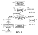
- the operation of the re-use detection system will now be described with reference to Figures 1 to 4 , and also to the flow diagrams of Figures 5 & 6 .
- the instrument 12 is connected to the generator 10 (step 70), and the instrument identification is carried out as described above (step 71). If the instrument is not recognized, it is rejected, but if the instrument is recognized as an acceptable instrument the process moves to step 72.
- the generator 10 interrogates the memory of the digital device 50 to see if the memory contains a previous value from the counter 51. If the memory is blank, the generator concludes that this is the first use of the instrument 12 (step 73), and writes the current value of the counter 51 (value1) to the digital device (step 74). The counter 51 is then incremented in value by one, to designate that an instrument has been connected to the generator (step 75), and the instrument is authorized for use (step 76).
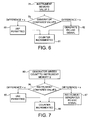
- step 77 the generator concludes that the instrument 12 has been previously used (step 77), and goes through the steps illustrated in Figure 6 .
- step 78 the generator reads the value (value0) stored in the memory of the digital device 50 from its previous connection to the generator 10.
- step 79 the comparison circuit 53 of the generator compares the stored value (value0) with the current value of the counter (value1). If the difference between the two values is less than a predetermined threshold x (say, for example 10), then the generator permits the use of the instrument 12 (step 80), and increments the counter 51 (step 81).
- a predetermined threshold x say, for example 10
- the generator concludes that the instrument 12 is a reprocessed instrument and generates a re-use signal (step 82). Even if the re-use signal is generated, the generator increments the counter 51 to record that a new attempt has been made to connect an instrument to the generator 10.
- the controller 22 may be programmed such that when it receives a re-use signal, the activation of the generator with the instrument 12 is prevented, and a display on the generator displays a warning message (such as "Re-used Instrument”).
- the controller 22 may alternatively be programmed to allow the instrument 12 to be used, but to record the use in a log that can be accessed subsequently. Other options include the sounding of an audible alarm, or the altering of the settings of the generator to allow the operation of the instrument 12 but only at reduced power settings.
- the generator concludes that the instrument is a reprocessed instrument and generates the re-use signal at step 82.
- Figure 7 illustrates the process with an alternative version of the re-use identification system, in which the comparison is carried out not within the generator but within the instrument 12.
- the digital memory device has at least two memory locations (memory1 and memory2), and the comparison circuit 53 is also included within the instrument 12.
- the first part of the process is similar to that previously described with reference to Figure 5 , with the generator 10 reading the memory in the digital device (in this case memory1) to see if it is blank. If it is indeed blank, the current value of the counter (value1) is written to memory1 of the digital device 50 (in step 74).
- the generator If memory1 in the digital device 50 is not blank, the generator writes the current value of the counter (value1) to memory2 of the digital device (see step 83 in Figure 7 ).
- the comparison circuit 53 within the instrument 12 compares the values in memory1 and memory2 to see if the difference is greater than the threshold x (step 84). As before, if the difference is less than the threshold x, use is permitted (step 85) and the counter within the generator is incremented (step 86). If the difference is greater than the threshold x, the re-use signal is generated (step 87) and sent to the generator for action.
Landscapes
- Health & Medical Sciences (AREA)
- Surgery (AREA)
- Engineering & Computer Science (AREA)
- Life Sciences & Earth Sciences (AREA)
- Biomedical Technology (AREA)
- Otolaryngology (AREA)
- Nuclear Medicine, Radiotherapy & Molecular Imaging (AREA)
- Plasma & Fusion (AREA)
- Physics & Mathematics (AREA)
- Heart & Thoracic Surgery (AREA)
- Medical Informatics (AREA)
- Molecular Biology (AREA)
- Animal Behavior & Ethology (AREA)
- General Health & Medical Sciences (AREA)
- Public Health (AREA)
- Veterinary Medicine (AREA)
- Surgical Instruments (AREA)
Abstract
Description
- This invention relates to an electrosurgical system including an electrosurgical generator and electrosurgical instruments for use therewith.
- Electrosurgical instruments are frequently recommended as "single use" instruments, meaning that they should be disposed of after use. However, such instruments are sometimes re-used against the wishes of the manufacturers, mostly after re-sterilisation. In fact, "Reprocessing" companies have been set up to take surgical instruments and reprocess them ready for re-use, despite the recommendations of the manufacturers that this is not desirable.
- Some systems have been designed to identify when a surgical instrument is being re-used or over-used, and to prevent the activation of such instruments when such activity has been detected. Examples of such systems are to be found in
US patents 5,383,874 ,5,651,780 ,5,400,267 ,6,237,604 and others. Frequently, such systems provide a memory device with a unique code within each instrument, and log the usage of such devices by reading the code when the device is connected to a controller or generator. - The present invention attempts to provide an alternative to such re-use detection systems, which allows for a flexible approach capable of allowing, monitoring or preventing re-use, as appropriate.
- Accordingly, an electrosurgical system is provided comprising:
- a generator for generating radio frequency power, and
- an electrosurgical instrument including an electrode assembly, the electrosurgical instrument being detachably connectible to the generator such that radio frequency power can be conveyed to the electrode assembly,
- characterised in that the generator includes a counter incremented each time an electrosurgical instrument is connected to the generator, the electrosurgical instrument includes a memory device capable of recording the value of the counter when the electrosurgical instrument is connected to the generator, and the system includes a comparison unit capable of comparing the current value of the counter with the value of the counter stored in the memory device, and generating a signal when the difference between the two values of the counter is greater than a predetermined threshold.
- The invention relies on the likelihood that, for a single-use instrument to be reprocessed for re-use, it will need to be sent away for sterilization. While the instrument is being reprocessed, the generator will likely be used with other instruments. Thus, if the incremental counter is incremented every time that an instrument is connected to the generator, the counter will be at a much higher value by the time that a reprocessed instrument is re-presented to the generator. This difference between the original value of the counter and the current value of the counter can be used to indicate the likelihood that there is an attempt to re-use a previously-used instrument.
- Preferably, the predetermined threshold between the two values of the counter is greater than one. In this way, should there be a problem with the equipment before or during a surgical procedure, which necessitates the disconnection and reconnection of the surgical instrument from the generator, the continued use of the instrument is allowed. This means that the re-use detection system does not operate in legitimate circumstances where reconnection of an electrosurgical instrument is essential, for example to continue with a procedure that is somehow interrupted or continued after a break. On the other hand, the system will serve to identify situations where the gap between the original use and the attempted re-use is so large that reprocessing of a single use instrument is the most likely cause. Conveniently, the predetermined threshold is between 5 and 10, allowing this many reconnections (or the use of other instruments in between) before a re-use signal is generated.
- In some circumstances the predetermined threshold is greater than 10. This would be appropriate for generators where the usage is relatively heavy, and the counter would most likely be well advanced by the time that any reprocessed instruments were returned to the operating theater. The threshold may be set differently for generators in different hospitals or surgical practices, or for different countries or regions. Additionally or alternatively, the threshold may be set differently for one type of instrument as opposed to another. For example, an instrument used for a first procedure may need to be disconnected and reconnected during the procedure, whereas an instrument used for a different procedure may not. Different thresholds can therefore take into account these differences in the accepted usage of these instruments.
- The comparison unit is conveniently present in the generator. In this arrangement, the generator reads the stored counter value from the memory of the electrosurgical instrument, and compares it with the current value of the counter within the generator. If the difference is above the threshold, a signal is generated to indicate an attempt to re-use the instrument. It is possible that the generator may have a plurality of incremental counters, one for each type of instrument used therewith. Most electrosurgical systems have some form of identification system for detecting which type of instrument is connected to the generator. In this arrangement, the generator increments the counter appropriate for whichever type of instrument is detected, and so an independent record of the usage of different instruments is obtained. Additionally or alternatively, a single incremental counter can be incremented whenever an instrument is connected to the generator, regardless of which type of instrument is connected.
- Conceivably, the comparison unit is present in the electrosurgical instrument. In this arrangement, the generator writes the value of the counter to a first memory within the instrument when the instrument is first connected to the generator. When the instrument is reconnected, the generator writes the current value of the counter to a second memory within the instrument. The comparison circuitry within the instrument compares the values in the first and second memories, and establishes whether the difference therebetween is greater than the allowed threshold. If the difference is too great, a re-use signal is generated and sent to the generator.
- According to one arrangement, the generator displays a warning message in response to the signal. This alerts the user to the suspicion that the instrument presented to the generator may have been reprocessed. The generator may still allow the reprocessed instrument to be used, or may alternatively prevent the usage thereof. Additionally or alternatively, the generator generates an audible alarm in response to the signal. Once again, this will alert the user to the use of a reprocessed instrument. Preferably, the generator blocks the supply of radio frequency power to the electrode assembly in response to the signal. Alternatively, the generator may allow the reprocessed instrument to be used, but at a reduced power setting in order to offset any impaired performance or reduced safety margins that may have been introduced by the reprocessing of the instrument.
- Various combinations of the above may conveniently be employed. For example, the generator may create a log of the re-use of the instruments, capable of being downloaded by a service engineer to keep track of the usage of the generator. Additionally or alternatively, the generator or the memory device stores information regarding the number of times the signal has been generated when the electrosurgical instrument has been connected to the generator. Conceivably, the generator makes a different response depending on the number of times that the signal has been generated. Thus, if the difference between the counter values indicated that a single use instrument was being re-used for the first time, re-use may be permitted or permitted at a lower power setting. If the same instrument was subsequently detected as being presented to the generator for use a third or subsequent time, the activation of the instrument could be prevented, or allowed only at progressively lower and lower power settings in order to preserve the appropriate safety margins. Additionally or alternatively, the visual or audible indications can change in content or severity as further re-use is detected, thereby warning the user that the risk of impaired performance is increasing.
- The invention further resides in a method of monitoring re-use of an electrosurgical instrument comprising the steps of
- i) connecting the electrosurgical instrument to an electrosurgical generator,
- ii) detecting whether the electrosurgical instrument has been connected previously to an electrosurgical generator,
- iii) if the electrosurgical instrument has not been connected previously to an electrosurgical generator, writing a value from an incremental counter housed in the generator to a memory present in the electrosurgical instrument, and
- iv) incrementing the incremental counter in response to the connection of the electrosurgical instrument.
- The method preferably also includes the additional steps of
- v) if the electrosurgical instrument has been connected previously to an electrosurgical generator, comparing the present value of the incremental counter with the value stored in the memory present in the electrosurgical instrument, and
- vi) generating a signal if the difference between the current value and the stored value exceeds a predetermined threshold.
- The invention will now be described in more detail, by way of example only, with reference to the accompanying drawings, in which;
-
Figure 1 is a diagrammatic representation of an electrosurgical system in accordance with the invention; -
Figure 2 is a circuit diagram of an electrosurgical instrument and identification circuitry for allowing an electrosurgical generator to be adjusted in response to connection of an electrosurgical instrument including a passive electrical identification component; -
Figure 3 is a set of three waveform diagrams relating to the circuitry ofFigure 2 ; -
Figure 4 is a circuit diagram of a connector forming part of an electrosurgical instrument which itself forms part of the electrosurgical system ofFigure 1 ; -
Figures 5 &6 are flow charts showing the operation of the invention in accordance with one embodiment thereof, and -
Figure 7 is a flow chart showing the operation of the invention in accordance with an alternative embodiment thereof. - Referring to
Figure 1 , an electrosurgical system in accordance with the invention comprises a first unit in the form of anelectrosurgical generator 10 for generating radio frequency power, and a second unit in the form of anelectrosurgical instrument 12 in the form of a pencil-grip handpiece and including an electrode assembly, ahandpiece body 12B, and aconnector 12C which is coupled to the handpiece body and the electrode assembly by acable 12D. Housed within theconnector 12C are two passiveelectrical identification components connector 12C is a multiple contact plug which mates with amultiple contact socket 16 on thegenerator 10 so that theinstrument 12 can be removably connected to the generator. - In this embodiment of the invention, the
electrode assembly 12A is a bipolar assembly having twotissue treatment electrodes 18. However, the assembly may comprise single or multiple electrode elements, in other words, monopolar, tripolar or multiple electrode assemblies. In the illustrated embodiment, theelectrodes 18 are connected via respective electrical conductors running through thehandpiece body 12B and thecable 12D to a respective pair of contacts (not shown inFigure 1 ) in theplug 12C. The capacitor 14 is also connected to a respective pair of contacts (not shown inFigure 1 ) in theplug 12C. - The generator comprises a radio frequency (RF)
oscillator 19 with a pair ofRF output lines 20 for feeding RF energy via thesocket 16 to the RF power contacts in theinstrument plug 12C for energising thebipolar electrodes 18. TheRF oscillator 19 is controlled by acontroller 22 which has connections to a user interface (not shown). Coupled to the controller is anelectrode identification circuit 24 havingconnections 26 to thesocket 16 for connecting to thecapacitors instrument 12 is coupled to thegenerator 10, theelectrode identification circuit 24 can be used to measure the value of the capacitors, detector output signals being conveyed bylines 28 to thecontroller 22 for controlling theRF oscillator 19 in response to the value of thecapacitors different instruments 12, the value of the capacitors can be used to identify theinstrument 12 and thereby cause adjustment of the generator RF output to suit each respective instrument when it is connected. To this extent, the system operates largely as described inU.S. Patent No. 6,074,386 , the entire disclosure of which is incorporated in the present specification by reference. - Measurement of capacitor values in the system will now be described with reference to the simplified circuit diagram of
Figure 2 and the accompanying waveform diagrams ofFigure 3 . - Referring to
Figure 2 , the electrosurgical instrument 12 (in the form of an electrode assembly having two electrodes 18) has a set ofcontacts 30, two of which constitute a pair of RF power contacts (30A, 30B) which are coupled to theelectrodes 18 of the instrument. An identification capacitor 14 is connected between one of theRF power contacts 30B and athird contact 30C of the set so that theelectrodes 18 and the capacitor 14 have onecommon contact 30B. On the generator side, the electrode identification circuit comprises asignal source 36 having atiming input 36A connected to the controller. Thesource 36 is configured to generate an interrogation pulse across a pair of source output lines 36B. Connected in series between thesource 36 and the capacitor 14 is an electrical component in the form of aninductance 38. Downstream of theinductor 38 is a shunt-connected dampingresistance 40. - The generator has a set of
contacts 42 which mate with thecontacts 30 of theinstrument 12, as shown. Output lines 44 from the RF oscillator 19 (not shown inFigure 2 ) are coupled tocontacts contacts instrument 12 so that electrosurgical RF energy is conveyed to theelectrodes 18 when theinstrument 12 is connected to the generator. Athird contact 42C on the generator is connected via theinductor 38 to one of the output lines 36B of thesignal source 36, whilst thecontact 42B which mates withinstrument contact 30B acting as a common contact for the capacitor 14 and one of theelectrodes 18 is not only connected to the output lines of the RF oscillator, but also to the other output line 36B of thesignal source 36. - It will be appreciated that when the
instrument 12 is connected to the generator, the capacitor 14 in the instrument and theseries inductance 38 in theidentification circuit 24 together form a series-resonant combination circuit having a resonant frequency determined by the values of the capacitor 14 and theinductor 38. Since capacitor 14 has different values depending uniquely on theinstrument 12 in which it is contained, the resonant frequency identifies theinstrument 12. - Coupled to the connection between the
inductor 38 and the capacitor 14 is one input of acomparator 46 the other input of which is connected to a reference voltage source VREF. This reference voltage is at a predetermined potential with respect to the other arm of the resonant circuit formed by capacitor 14 and inductor 38 (here the output line 36B of the signal source which is not connected to the inductor 38).Comparator 46 has an output connected to asignal processing circuit 48 which, in turn, feeds the controller 22 (seeFigure 1 ) via itsoutput 48A. - It will be appreciated that when the voltage step-change represented by the leading edge of the interrogation pulse generated by
signal source 36 is applied to the resonant combination of capacitor 14 andinductor 38, a ringing signal is generated at the junction between capacitor 14 andinductor 38, the ringing occurring at the resonant frequency referred to above. Owing to the presence of theparallel resistance 40, the ringing signal decays predictably. In practice, the value of theresistance 40 is chosen such that its effect upon the decay rate of the ringing of the signal is minimised, but its effect in the presence of noise is maximised, its main purpose is for EMC protection and to keep the ringing of the resonant network to predictable values. The value of the voltage reference source VREF is selected such that, during the interrogation pulse, the ringing signal crosses over the reference voltage several times, with the effect that a corresponding binary signal appears at theoutput 46A of thecomparator 46, the binary signal taking the form of a squarewave having a repetition rate equal to the resonant frequency of the capacitor/inductor combination. In this example, thesignal processing circuit 48 measures the interval between successive edges of the squarewave, thereby detecting the pulse width of the squarewave signal and, hence, the period of the ringing signal. As an alternative,signal processing circuit 48 may employ a counter arranged to count the number of changes of state of the output signal from thecomparator 46 as a means of determining the ringing frequency or period. - The interrogation pulse is shown by waveform diagram (1) in
Figure 3 . The ringing signal is shown in diagram (2) and the squarewave signal outputted by thecomparator 46 is shown by diagram (3) inFigure 3 . - It will be appreciated that detecting the transient response of the resonant combination of the capacitor 14 and
inductor 38 rather than using the resonant combination to determine the frequency of oscillation of an identification circuit oscillator as inU.S. 6,074,386 , allows the contacts coupling the identification capacitor 14 to the identification circuit of thegenerator 10 to be used for different purposes at times other than during the transient response. In other words, sensing oscillations in the resonant combination only for a short period permits sharing of the connections, in ways that will be described below. - In the system described above with reference to
Figure 2 , the identification components (capacitors connector 12C forming part of aninstrument 12 detachably connected to thegenerator 10. In this case, thegenerator 10 constitutes the "first unit" and thecomplete instrument 12 constitutes the "second unit", the connection interface occurring between theplug 12C and thesocket 16. In an alternative embodiment, the first unit may be an instrument body and the second unit a sterilisable instrument part (not shown). Thus, theinstrument 12 may have adetachable electrode assembly 12A and the capacitor may be housed in the detachable part, so that the connection interface, for the purpose of identification, is not between theplug 12C and thesocket 16 but between mutually separable parts of theinstrument 12. - Referring to
Figure 4 , in a preferred embodiment of the invention, theconnector 12C houses twoidentification components connector 12C also houses adigital device 50 which operates through the same contacts of theconnector 12C as thecapacitors connector 12C has a contact set 30 comprising four contacts two of which 30A, 30B are used for RF power and are coupled tolines 52A, 52B passing through the connector to thecable 12D and electrodes 18 (seeFigure 1 ). In this case, bothcapacitors RF power contacts 30B. The other terminals are connected torespective identification contacts identification contacts digital device 50. As will be seen fromFigure 4 ,digital device 50 has apower supply line 54 coupled to identification contact 30C via anintermediate circuit 56, and adata output 58 coupled toidentification contact 30D via a secondintermediate circuit 60. A local 0V signal andpower return terminal 62 of thedigital device 50 is coupled to theline 52B, thereby sharingcontact 30B not only with the electrodes of the instrument, but also with thefirst capacitor 14A. - Referring back to
Figure 1 ,controller 22 includes acounter 51 and acomparison circuit 53. Thecontroller 22 and the interconnections between the controller and thedigital device 50 in theinstrument 12 are configured and arranged such that a count value outputted by thecounter 51 can be written to a memory in thedigital device 50 and such that values stored in the digital device memory can be read out by the controller. The operation of the re-use detection system will now be described with reference toFigures 1 to 4 , and also to the flow diagrams ofFigures 5 &6 . - In use, the
instrument 12 is connected to the generator 10 (step 70), and the instrument identification is carried out as described above (step 71). If the instrument is not recognized, it is rejected, but if the instrument is recognized as an acceptable instrument the process moves to step 72. In this step, thegenerator 10 interrogates the memory of thedigital device 50 to see if the memory contains a previous value from thecounter 51. If the memory is blank, the generator concludes that this is the first use of the instrument 12 (step 73), and writes the current value of the counter 51 (value1) to the digital device (step 74). Thecounter 51 is then incremented in value by one, to designate that an instrument has been connected to the generator (step 75), and the instrument is authorized for use (step 76). - If the memory is not blank in
step 72, then the generator concludes that theinstrument 12 has been previously used (step 77), and goes through the steps illustrated inFigure 6 . Instep 78, the generator reads the value (value0) stored in the memory of thedigital device 50 from its previous connection to thegenerator 10. Instep 79, thecomparison circuit 53 of the generator compares the stored value (value0) with the current value of the counter (value1). If the difference between the two values is less than a predetermined threshold x (say, for example 10), then the generator permits the use of the instrument 12 (step 80), and increments the counter 51 (step 81). If the difference is greater then the threshold x, then the generator concludes that theinstrument 12 is a reprocessed instrument and generates a re-use signal (step 82). Even if the re-use signal is generated, the generator increments thecounter 51 to record that a new attempt has been made to connect an instrument to thegenerator 10. - The
controller 22 may be programmed such that when it receives a re-use signal, the activation of the generator with theinstrument 12 is prevented, and a display on the generator displays a warning message (such as "Re-used Instrument"). Thecontroller 22 may alternatively be programmed to allow theinstrument 12 to be used, but to record the use in a log that can be accessed subsequently. Other options include the sounding of an audible alarm, or the altering of the settings of the generator to allow the operation of theinstrument 12 but only at reduced power settings. - Thus, where an original instrument is connected and disconnected to the generator within a reasonably short period of time (during which few if any instruments will have been connected), the difference between the two values (value1 and value0) will be less than the threshold x, and the use of the instrument will be permitted. This ensures that legitimate reasons for disconnecting and reconnecting the instrument do not result in the use of the instrument being barred. However, when the period of time is longer such that the number of uses between the original connection and reconnection means that the difference between the two values (value1 and value0) is greater than the threshold x, the generator concludes that the instrument is a reprocessed instrument and generates the re-use signal at
step 82. - Clearly, there may be other similar generators present in the same hospital or surgical center, or in other locations in general. Thus it is possible that the
instrument 12 could have been used with one generator in a first location, reprocessed, and presented to a different generator in a different location. In these circumstances, due to the different rates of usage experienced with different generators, it is highly unlikely that the value of the counters of the two different generators will be within the threshold x. Thus the attempted re-use of an instrument will be identified, even if the use is attempted with different generators. -
Figure 7 illustrates the process with an alternative version of the re-use identification system, in which the comparison is carried out not within the generator but within theinstrument 12. In this arrangement the digital memory device has at least two memory locations (memory1 and memory2), and thecomparison circuit 53 is also included within theinstrument 12. The first part of the process is similar to that previously described with reference toFigure 5 , with thegenerator 10 reading the memory in the digital device (in this case memory1) to see if it is blank. If it is indeed blank, the current value of the counter (value1) is written to memory1 of the digital device 50 (in step 74). - If memory1 in the
digital device 50 is not blank, the generator writes the current value of the counter (value1) to memory2 of the digital device (seestep 83 inFigure 7 ). Thecomparison circuit 53 within theinstrument 12 then compares the values in memory1 and memory2 to see if the difference is greater than the threshold x (step 84). As before, if the difference is less than the threshold x, use is permitted (step 85) and the counter within the generator is incremented (step 86). If the difference is greater than the threshold x, the re-use signal is generated (step 87) and sent to the generator for action. - The invention has been described in such a way that variations to the way the re-use signal is generated, as well as the way in which actions are taken in response to the re-use signal, will be apparent to those skilled in the art. Thus the system may be customised to various circumstances, including the type of instrument connected to the generator, the procedure to be performed, or the country or region of operation.
Claims (14)
- An electrosurgical system comprising:a generator (10) for generating radio frequency power, andan electrosurgical instrument (12) including an electrode assembly, the electrosurgical instrument being detachably connectible to the generator such that radio frequency power can be conveyed to the electrode assembly,characterised in that the generator includes a counter (51) incremented each time an electrosurgical instrument is connected to the generator, the electrosurgical instrument includes a memory device (50) capable of recording the value of the counter when the electrosurgical instrument is connected to the generator, and the system includes a comparison unit (53) capable of comparing the current value of the counter with the value of the counter stored in the memory device, and generating a signal when the difference between the two values of the counter is greater than a predetermined threshold.
- An electrosurgical system according to claim 1, characterised in that the predetermined threshold is greater than one.
- An electrosurgical system according to claim 2, characterised in that the predetermined threshold is between 5 and 10.
- An electrosurgical system according to claim 2, characterised in that the predetermined threshold is greater than 10.
- An electrosurgical system according to any preceding claim, characterised in that the comparison unit (53) is present in the generator (10).
- An electrosurgical system according to any of claims 1 to 4, characterised in that the comparison unit (53) is present in the electrosurgical instrument (12).
- An electrosurgical system according to any preceding claim, characterised in that the generator (10) displays a warning message in response to the signal.
- An electrosurgical system according to any preceding claim, characterised in that the generator (10) generates an audible alarm in response to the signal.
- An electrosurgical system according to any preceding claim, characterised in that the generator (10) reduces the power of the radio frequency supplied to the electrode assembly in response to the signal.
- An electrosurgical system according to any preceding claim, characterised in that the generator (10) blocks the supply of radio frequency power to the electrode assembly in response to the signal.
- An electrosurgical system according to any preceding claim, characterised in that the generator (10) or the memory device (50) stores information regarding the number of times the signal has been generated when the electrosurgical instrument (12) has been connected to the generator.
- An electrosurgical system according to claim 11, characterised in that the generator (10) makes a different response depending on the number of times that the signal has been generated.
- A method of monitoring re-use of an electrosurgical instrument (12) comprising the steps of:i) connecting the electrosurgical instrument (12) to an electrosurgical generator (10),ii) detecting whether the electrosurgical instrument has been connected previously to an electrosurgical generator,iii) if the electrosurgical instrument has not been connected previously to an electrosurgical generator, writing a value from an incremental counter (51) housed in the generator to a memory (50) present in the electrosurgical instrument, andiv) incrementing the incremental counter in response to the connection of the electrosurgical instrument.
- A method of monitoring re-use according to claim 13, characterised by the further steps of:v) if the electrosurgical instrument (12) has been connected previously to an electrosurgical generator (10), comparing the present value of the incremental counter (51) with the value stored in the memory (50) present in the electrosurgical instrument (12), andvi) generating a signal if the difference between the current value and the stored value exceeds a predetermined threshold.
Applications Claiming Priority (1)
| Application Number | Priority Date | Filing Date | Title |
|---|---|---|---|
| GBGB0716590.5A GB0716590D0 (en) | 2007-08-24 | 2007-08-24 | Electrosurgical system |
Publications (2)
| Publication Number | Publication Date |
|---|---|
| EP2027825A1 true EP2027825A1 (en) | 2009-02-25 |
| EP2027825B1 EP2027825B1 (en) | 2015-09-30 |
Family
ID=38599258
Family Applications (1)
| Application Number | Title | Priority Date | Filing Date |
|---|---|---|---|
| EP08252679.9A Not-in-force EP2027825B1 (en) | 2007-08-24 | 2008-08-13 | Electrosurgical system |
Country Status (3)
| Country | Link |
|---|---|
| US (1) | US20090054889A1 (en) |
| EP (1) | EP2027825B1 (en) |
| GB (1) | GB0716590D0 (en) |
Families Citing this family (124)
| Publication number | Priority date | Publication date | Assignee | Title |
|---|---|---|---|---|
| US10835307B2 (en) | 2001-06-12 | 2020-11-17 | Ethicon Llc | Modular battery powered handheld surgical instrument containing elongated multi-layered shaft |
| US8182501B2 (en) | 2004-02-27 | 2012-05-22 | Ethicon Endo-Surgery, Inc. | Ultrasonic surgical shears and method for sealing a blood vessel using same |
| PL1802245T3 (en) | 2004-10-08 | 2017-01-31 | Ethicon Endosurgery Llc | Ultrasonic surgical instrument |
| US20070191713A1 (en) | 2005-10-14 | 2007-08-16 | Eichmann Stephen E | Ultrasonic device for cutting and coagulating |
| US7621930B2 (en) | 2006-01-20 | 2009-11-24 | Ethicon Endo-Surgery, Inc. | Ultrasound medical instrument having a medical ultrasonic blade |
| US8142461B2 (en) | 2007-03-22 | 2012-03-27 | Ethicon Endo-Surgery, Inc. | Surgical instruments |
| US8911460B2 (en) | 2007-03-22 | 2014-12-16 | Ethicon Endo-Surgery, Inc. | Ultrasonic surgical instruments |
| US8057498B2 (en) | 2007-11-30 | 2011-11-15 | Ethicon Endo-Surgery, Inc. | Ultrasonic surgical instrument blades |
| US8808319B2 (en) | 2007-07-27 | 2014-08-19 | Ethicon Endo-Surgery, Inc. | Surgical instruments |
| US8523889B2 (en) | 2007-07-27 | 2013-09-03 | Ethicon Endo-Surgery, Inc. | Ultrasonic end effectors with increased active length |
| US9044261B2 (en) | 2007-07-31 | 2015-06-02 | Ethicon Endo-Surgery, Inc. | Temperature controlled ultrasonic surgical instruments |
| US8430898B2 (en) | 2007-07-31 | 2013-04-30 | Ethicon Endo-Surgery, Inc. | Ultrasonic surgical instruments |
| US8512365B2 (en) | 2007-07-31 | 2013-08-20 | Ethicon Endo-Surgery, Inc. | Surgical instruments |
| AU2008308606B2 (en) | 2007-10-05 | 2014-12-18 | Ethicon Endo-Surgery, Inc. | Ergonomic surgical instruments |
| US10010339B2 (en) | 2007-11-30 | 2018-07-03 | Ethicon Llc | Ultrasonic surgical blades |
| US9089360B2 (en) | 2008-08-06 | 2015-07-28 | Ethicon Endo-Surgery, Inc. | Devices and techniques for cutting and coagulating tissue |
| US9700339B2 (en) | 2009-05-20 | 2017-07-11 | Ethicon Endo-Surgery, Inc. | Coupling arrangements and methods for attaching tools to ultrasonic surgical instruments |
| US8663220B2 (en) | 2009-07-15 | 2014-03-04 | Ethicon Endo-Surgery, Inc. | Ultrasonic surgical instruments |
| US10441345B2 (en) | 2009-10-09 | 2019-10-15 | Ethicon Llc | Surgical generator for ultrasonic and electrosurgical devices |
| US8956349B2 (en) | 2009-10-09 | 2015-02-17 | Ethicon Endo-Surgery, Inc. | Surgical generator for ultrasonic and electrosurgical devices |
| US11090104B2 (en) | 2009-10-09 | 2021-08-17 | Cilag Gmbh International | Surgical generator for ultrasonic and electrosurgical devices |
| US8951272B2 (en) | 2010-02-11 | 2015-02-10 | Ethicon Endo-Surgery, Inc. | Seal arrangements for ultrasonically powered surgical instruments |
| US8469981B2 (en) | 2010-02-11 | 2013-06-25 | Ethicon Endo-Surgery, Inc. | Rotatable cutting implement arrangements for ultrasonic surgical instruments |
| US8486096B2 (en) | 2010-02-11 | 2013-07-16 | Ethicon Endo-Surgery, Inc. | Dual purpose surgical instrument for cutting and coagulating tissue |
| US8795327B2 (en) | 2010-07-22 | 2014-08-05 | Ethicon Endo-Surgery, Inc. | Electrosurgical instrument with separate closure and cutting members |
| US9192431B2 (en) | 2010-07-23 | 2015-11-24 | Ethicon Endo-Surgery, Inc. | Electrosurgical cutting and sealing instrument |
| US9730717B2 (en) * | 2011-02-03 | 2017-08-15 | Karl Storz Gmbh & Co. Kg | Medical manipulator system |
| US9259265B2 (en) | 2011-07-22 | 2016-02-16 | Ethicon Endo-Surgery, Llc | Surgical instruments for tensioning tissue |
| JP6165780B2 (en) | 2012-02-10 | 2017-07-19 | エシコン・エンド−サージェリィ・インコーポレイテッドEthicon Endo−Surgery,Inc. | Robot-controlled surgical instrument |
| US9439668B2 (en) | 2012-04-09 | 2016-09-13 | Ethicon Endo-Surgery, Llc | Switch arrangements for ultrasonic surgical instruments |
| US9204920B2 (en) | 2012-05-02 | 2015-12-08 | Covidien Lp | External reader for device management |
| US20140005705A1 (en) | 2012-06-29 | 2014-01-02 | Ethicon Endo-Surgery, Inc. | Surgical instruments with articulating shafts |
| US9408622B2 (en) | 2012-06-29 | 2016-08-09 | Ethicon Endo-Surgery, Llc | Surgical instruments with articulating shafts |
| US20140005702A1 (en) | 2012-06-29 | 2014-01-02 | Ethicon Endo-Surgery, Inc. | Ultrasonic surgical instruments with distally positioned transducers |
| US9820768B2 (en) | 2012-06-29 | 2017-11-21 | Ethicon Llc | Ultrasonic surgical instruments with control mechanisms |
| US9326788B2 (en) | 2012-06-29 | 2016-05-03 | Ethicon Endo-Surgery, Llc | Lockout mechanism for use with robotic electrosurgical device |
| US9226767B2 (en) | 2012-06-29 | 2016-01-05 | Ethicon Endo-Surgery, Inc. | Closed feedback control for electrosurgical device |
| US9393037B2 (en) | 2012-06-29 | 2016-07-19 | Ethicon Endo-Surgery, Llc | Surgical instruments with articulating shafts |
| US9198714B2 (en) | 2012-06-29 | 2015-12-01 | Ethicon Endo-Surgery, Inc. | Haptic feedback devices for surgical robot |
| US9351754B2 (en) | 2012-06-29 | 2016-05-31 | Ethicon Endo-Surgery, Llc | Ultrasonic surgical instruments with distally positioned jaw assemblies |
| JP6275727B2 (en) | 2012-09-28 | 2018-02-07 | エシコン・エンド−サージェリィ・インコーポレイテッドEthicon Endo−Surgery,Inc. | Multifunctional bipolar forceps |
| US9095367B2 (en) | 2012-10-22 | 2015-08-04 | Ethicon Endo-Surgery, Inc. | Flexible harmonic waveguides/blades for surgical instruments |
| US20140135804A1 (en) | 2012-11-15 | 2014-05-15 | Ethicon Endo-Surgery, Inc. | Ultrasonic and electrosurgical devices |
| US9364277B2 (en) | 2012-12-13 | 2016-06-14 | Cook Medical Technologies Llc | RF energy controller and method for electrosurgical medical devices |
| US9204921B2 (en) | 2012-12-13 | 2015-12-08 | Cook Medical Technologies Llc | RF energy controller and method for electrosurgical medical devices |
| US10226273B2 (en) | 2013-03-14 | 2019-03-12 | Ethicon Llc | Mechanical fasteners for use with surgical energy devices |
| US9814514B2 (en) | 2013-09-13 | 2017-11-14 | Ethicon Llc | Electrosurgical (RF) medical instruments for cutting and coagulating tissue |
| US9265926B2 (en) | 2013-11-08 | 2016-02-23 | Ethicon Endo-Surgery, Llc | Electrosurgical devices |
| GB2521228A (en) | 2013-12-16 | 2015-06-17 | Ethicon Endo Surgery Inc | Medical device |
| GB2521229A (en) | 2013-12-16 | 2015-06-17 | Ethicon Endo Surgery Inc | Medical device |
| US9795436B2 (en) | 2014-01-07 | 2017-10-24 | Ethicon Llc | Harvesting energy from a surgical generator |
| US9554854B2 (en) | 2014-03-18 | 2017-01-31 | Ethicon Endo-Surgery, Llc | Detecting short circuits in electrosurgical medical devices |
| US10463421B2 (en) | 2014-03-27 | 2019-11-05 | Ethicon Llc | Two stage trigger, clamp and cut bipolar vessel sealer |
| US10092310B2 (en) | 2014-03-27 | 2018-10-09 | Ethicon Llc | Electrosurgical devices |
| US9737355B2 (en) | 2014-03-31 | 2017-08-22 | Ethicon Llc | Controlling impedance rise in electrosurgical medical devices |
| JP6915990B2 (en) * | 2014-04-09 | 2021-08-11 | ジャイラス エーシーエムアイ インク | Enforcement device for products with restricted use |
| US9913680B2 (en) | 2014-04-15 | 2018-03-13 | Ethicon Llc | Software algorithms for electrosurgical instruments |
| US10285724B2 (en) | 2014-07-31 | 2019-05-14 | Ethicon Llc | Actuation mechanisms and load adjustment assemblies for surgical instruments |
| US10639092B2 (en) | 2014-12-08 | 2020-05-05 | Ethicon Llc | Electrode configurations for surgical instruments |
| US10245095B2 (en) | 2015-02-06 | 2019-04-02 | Ethicon Llc | Electrosurgical instrument with rotation and articulation mechanisms |
| US10321950B2 (en) | 2015-03-17 | 2019-06-18 | Ethicon Llc | Managing tissue treatment |
| US10342602B2 (en) | 2015-03-17 | 2019-07-09 | Ethicon Llc | Managing tissue treatment |
| US10595929B2 (en) | 2015-03-24 | 2020-03-24 | Ethicon Llc | Surgical instruments with firing system overload protection mechanisms |
| US11020140B2 (en) | 2015-06-17 | 2021-06-01 | Cilag Gmbh International | Ultrasonic surgical blade for use with ultrasonic surgical instruments |
| US10034704B2 (en) * | 2015-06-30 | 2018-07-31 | Ethicon Llc | Surgical instrument with user adaptable algorithms |
| US10898256B2 (en) | 2015-06-30 | 2021-01-26 | Ethicon Llc | Surgical system with user adaptable techniques based on tissue impedance |
| US11141213B2 (en) | 2015-06-30 | 2021-10-12 | Cilag Gmbh International | Surgical instrument with user adaptable techniques |
| US11129669B2 (en) | 2015-06-30 | 2021-09-28 | Cilag Gmbh International | Surgical system with user adaptable techniques based on tissue type |
| US11051873B2 (en) | 2015-06-30 | 2021-07-06 | Cilag Gmbh International | Surgical system with user adaptable techniques employing multiple energy modalities based on tissue parameters |
| US10357303B2 (en) | 2015-06-30 | 2019-07-23 | Ethicon Llc | Translatable outer tube for sealing using shielded lap chole dissector |
| US10154852B2 (en) | 2015-07-01 | 2018-12-18 | Ethicon Llc | Ultrasonic surgical blade with improved cutting and coagulation features |
| US10736685B2 (en) | 2015-09-30 | 2020-08-11 | Ethicon Llc | Generator for digitally generating combined electrical signal waveforms for ultrasonic surgical instruments |
| US10595930B2 (en) | 2015-10-16 | 2020-03-24 | Ethicon Llc | Electrode wiping surgical device |
| US10179022B2 (en) | 2015-12-30 | 2019-01-15 | Ethicon Llc | Jaw position impedance limiter for electrosurgical instrument |
| US10575892B2 (en) | 2015-12-31 | 2020-03-03 | Ethicon Llc | Adapter for electrical surgical instruments |
| US12193698B2 (en) | 2016-01-15 | 2025-01-14 | Cilag Gmbh International | Method for self-diagnosing operation of a control switch in a surgical instrument system |
| US10716615B2 (en) | 2016-01-15 | 2020-07-21 | Ethicon Llc | Modular battery powered handheld surgical instrument with curved end effectors having asymmetric engagement between jaw and blade |
| US11129670B2 (en) | 2016-01-15 | 2021-09-28 | Cilag Gmbh International | Modular battery powered handheld surgical instrument with selective application of energy based on button displacement, intensity, or local tissue characterization |
| US10828058B2 (en) | 2016-01-15 | 2020-11-10 | Ethicon Llc | Modular battery powered handheld surgical instrument with motor control limits based on tissue characterization |
| US11229471B2 (en) | 2016-01-15 | 2022-01-25 | Cilag Gmbh International | Modular battery powered handheld surgical instrument with selective application of energy based on tissue characterization |
| US10555769B2 (en) | 2016-02-22 | 2020-02-11 | Ethicon Llc | Flexible circuits for electrosurgical instrument |
| US10485607B2 (en) | 2016-04-29 | 2019-11-26 | Ethicon Llc | Jaw structure with distal closure for electrosurgical instruments |
| US10702329B2 (en) | 2016-04-29 | 2020-07-07 | Ethicon Llc | Jaw structure with distal post for electrosurgical instruments |
| US10646269B2 (en) | 2016-04-29 | 2020-05-12 | Ethicon Llc | Non-linear jaw gap for electrosurgical instruments |
| US10456193B2 (en) | 2016-05-03 | 2019-10-29 | Ethicon Llc | Medical device with a bilateral jaw configuration for nerve stimulation |
| US10245064B2 (en) | 2016-07-12 | 2019-04-02 | Ethicon Llc | Ultrasonic surgical instrument with piezoelectric central lumen transducer |
| US10893883B2 (en) | 2016-07-13 | 2021-01-19 | Ethicon Llc | Ultrasonic assembly for use with ultrasonic surgical instruments |
| US10842522B2 (en) | 2016-07-15 | 2020-11-24 | Ethicon Llc | Ultrasonic surgical instruments having offset blades |
| US10376305B2 (en) | 2016-08-05 | 2019-08-13 | Ethicon Llc | Methods and systems for advanced harmonic energy |
| US10285723B2 (en) | 2016-08-09 | 2019-05-14 | Ethicon Llc | Ultrasonic surgical blade with improved heel portion |
| USD847990S1 (en) | 2016-08-16 | 2019-05-07 | Ethicon Llc | Surgical instrument |
| US10952759B2 (en) | 2016-08-25 | 2021-03-23 | Ethicon Llc | Tissue loading of a surgical instrument |
| US10736649B2 (en) | 2016-08-25 | 2020-08-11 | Ethicon Llc | Electrical and thermal connections for ultrasonic transducer |
| US10603064B2 (en) | 2016-11-28 | 2020-03-31 | Ethicon Llc | Ultrasonic transducer |
| US11266430B2 (en) | 2016-11-29 | 2022-03-08 | Cilag Gmbh International | End effector control and calibration |
| US10820920B2 (en) | 2017-07-05 | 2020-11-03 | Ethicon Llc | Reusable ultrasonic medical devices and methods of their use |
| US12343063B2 (en) | 2019-12-30 | 2025-07-01 | Cilag Gmbh International | Multi-layer clamp arm pad for enhanced versatility and performance of a surgical device |
| US11452525B2 (en) | 2019-12-30 | 2022-09-27 | Cilag Gmbh International | Surgical instrument comprising an adjustment system |
| US11986201B2 (en) | 2019-12-30 | 2024-05-21 | Cilag Gmbh International | Method for operating a surgical instrument |
| US12114912B2 (en) | 2019-12-30 | 2024-10-15 | Cilag Gmbh International | Non-biased deflectable electrode to minimize contact between ultrasonic blade and electrode |
| US11812957B2 (en) | 2019-12-30 | 2023-11-14 | Cilag Gmbh International | Surgical instrument comprising a signal interference resolution system |
| US11660089B2 (en) | 2019-12-30 | 2023-05-30 | Cilag Gmbh International | Surgical instrument comprising a sensing system |
| US12082808B2 (en) | 2019-12-30 | 2024-09-10 | Cilag Gmbh International | Surgical instrument comprising a control system responsive to software configurations |
| US12336747B2 (en) | 2019-12-30 | 2025-06-24 | Cilag Gmbh International | Method of operating a combination ultrasonic / bipolar RF surgical device with a combination energy modality end-effector |
| US20210196359A1 (en) | 2019-12-30 | 2021-07-01 | Ethicon Llc | Electrosurgical instruments with electrodes having energy focusing features |
| US11944366B2 (en) | 2019-12-30 | 2024-04-02 | Cilag Gmbh International | Asymmetric segmented ultrasonic support pad for cooperative engagement with a movable RF electrode |
| US12262937B2 (en) | 2019-12-30 | 2025-04-01 | Cilag Gmbh International | User interface for surgical instrument with combination energy modality end-effector |
| US12076006B2 (en) | 2019-12-30 | 2024-09-03 | Cilag Gmbh International | Surgical instrument comprising an orientation detection system |
| US11786291B2 (en) | 2019-12-30 | 2023-10-17 | Cilag Gmbh International | Deflectable support of RF energy electrode with respect to opposing ultrasonic blade |
| US11937866B2 (en) | 2019-12-30 | 2024-03-26 | Cilag Gmbh International | Method for an electrosurgical procedure |
| US12064109B2 (en) | 2019-12-30 | 2024-08-20 | Cilag Gmbh International | Surgical instrument comprising a feedback control circuit |
| US12702409B2 (en) | 2019-12-30 | 2026-08-11 | Cilag Gmbh International | Surgical instrument comprising a flex circuit |
| US11759251B2 (en) | 2019-12-30 | 2023-09-19 | Cilag Gmbh International | Control program adaptation based on device status and user input |
| US12023086B2 (en) | 2019-12-30 | 2024-07-02 | Cilag Gmbh International | Electrosurgical instrument for delivering blended energy modalities to tissue |
| US11911063B2 (en) | 2019-12-30 | 2024-02-27 | Cilag Gmbh International | Techniques for detecting ultrasonic blade to electrode contact and reducing power to ultrasonic blade |
| US11707318B2 (en) | 2019-12-30 | 2023-07-25 | Cilag Gmbh International | Surgical instrument with jaw alignment features |
| US11779329B2 (en) | 2019-12-30 | 2023-10-10 | Cilag Gmbh International | Surgical instrument comprising a flex circuit including a sensor system |
| US20210196358A1 (en) | 2019-12-30 | 2021-07-01 | Ethicon Llc | Electrosurgical instrument with electrodes biasing support |
| US11779387B2 (en) | 2019-12-30 | 2023-10-10 | Cilag Gmbh International | Clamp arm jaw to minimize tissue sticking and improve tissue control |
| US11950797B2 (en) | 2019-12-30 | 2024-04-09 | Cilag Gmbh International | Deflectable electrode with higher distal bias relative to proximal bias |
| US12053224B2 (en) | 2019-12-30 | 2024-08-06 | Cilag Gmbh International | Variation in electrode parameters and deflectable electrode to modify energy density and tissue interaction |
| US11696776B2 (en) | 2019-12-30 | 2023-07-11 | Cilag Gmbh International | Articulatable surgical instrument |
| US11937863B2 (en) | 2019-12-30 | 2024-03-26 | Cilag Gmbh International | Deflectable electrode with variable compression bias along the length of the deflectable electrode |
| WO2022132015A1 (en) | 2020-12-18 | 2022-06-23 | Arjo IP Holding Aktiebolag | Medical device control system, connector and coupling assembly with parameter indication |
Citations (8)
| Publication number | Priority date | Publication date | Assignee | Title |
|---|---|---|---|---|
| US5383874A (en) | 1991-11-08 | 1995-01-24 | Ep Technologies, Inc. | Systems for identifying catheters and monitoring their use |
| US5400267A (en) | 1992-12-08 | 1995-03-21 | Hemostatix Corporation | Local in-device memory feature for electrically powered medical equipment |
| US5425375A (en) * | 1993-09-09 | 1995-06-20 | Cardiac Pathways Corporation | Reusable medical device with usage memory, system using same |
| US5487386A (en) * | 1993-04-22 | 1996-01-30 | Kabushiki Kaisha Toshiba | Ultrasonic diagnostic apparatus |
| US6074386A (en) | 1995-12-29 | 2000-06-13 | Gyrus Medical Limited | Electrosurgical instrument and an electrosurgical electrode assembly |
| US6237604B1 (en) | 1999-09-07 | 2001-05-29 | Scimed Life Systems, Inc. | Systems and methods for preventing automatic identification of re-used single use devices |
| US6651669B1 (en) * | 1999-09-07 | 2003-11-25 | Scimed Life Systems, Inc. | Systems and methods to identify and disable re-used single use devices based on cataloging catheter usage |
| US20060079880A1 (en) * | 2004-10-13 | 2006-04-13 | Sage Shahn S | Transurethral needle ablation system with flexible catheter tip |
Family Cites Families (21)
| Publication number | Priority date | Publication date | Assignee | Title |
|---|---|---|---|---|
| NL193256C (en) * | 1981-11-10 | 1999-04-02 | Cordis Europ | Sensor system. |
| US6165169A (en) * | 1994-03-04 | 2000-12-26 | Ep Technologies, Inc. | Systems and methods for identifying the physical, mechanical, and functional attributes of multiple electrode arrays |
| US6464689B1 (en) * | 1999-09-08 | 2002-10-15 | Curon Medical, Inc. | Graphical user interface for monitoring and controlling use of medical devices |
| US5523746A (en) * | 1994-09-01 | 1996-06-04 | Gallagher; Robert R. | Identification system with a passive activator |
| US6409722B1 (en) * | 1998-07-07 | 2002-06-25 | Medtronic, Inc. | Apparatus and method for creating, maintaining, and controlling a virtual electrode used for the ablation of tissue |
| US5817092A (en) * | 1995-11-09 | 1998-10-06 | Radio Therapeutics Corporation | Apparatus, system and method for delivering radio frequency energy to a treatment site |
| DE69732362T2 (en) * | 1996-02-15 | 2006-03-23 | Biosense Webster, Inc., Diamond Bar | Method for calibrating a probe |
| US5742718A (en) * | 1996-08-13 | 1998-04-21 | Eclipse Surgical Technologies, Inc. | Proprietary fiber connector and electronic security system |
| US6331181B1 (en) * | 1998-12-08 | 2001-12-18 | Intuitive Surgical, Inc. | Surgical robotic tools, data architecture, and use |
| SE9702679D0 (en) * | 1997-07-11 | 1997-07-11 | Siemens Elema Ab | Device for calculating the number of uses of a sensor |
| US6308089B1 (en) * | 1999-04-14 | 2001-10-23 | O.B. Scientific, Inc. | Limited use medical probe |
| US6611793B1 (en) * | 1999-09-07 | 2003-08-26 | Scimed Life Systems, Inc. | Systems and methods to identify and disable re-use single use devices based on detecting environmental changes |
| US6387092B1 (en) * | 1999-09-07 | 2002-05-14 | Scimed Life Systems, Inc. | Systems and methods to identify and disable re-used single use devices based on time elapsed from first therapeutic use |
| EP1210024A1 (en) * | 1999-09-08 | 2002-06-05 | Curon Medical, Inc. | System for controlling a family of treatment devices |
| AU1629001A (en) * | 1999-09-08 | 2001-04-10 | Curon Medical, Inc. | Systems and methods for monitoring and controlling use of medical devices |
| CA2384273A1 (en) * | 1999-09-08 | 2001-03-15 | Curon Medical, Inc. | Systems and methods for monitoring and controlling use of medical devices |
| JP2002124580A (en) * | 2000-10-18 | 2002-04-26 | Yamaha Corp | Input protection circuit |
| US6908472B2 (en) * | 2000-10-20 | 2005-06-21 | Ethicon Endo-Surgery, Inc. | Apparatus and method for altering generator functions in an ultrasonic surgical system |
| US20030204185A1 (en) * | 2002-04-26 | 2003-10-30 | Sherman Marshall L. | System and method for monitoring use of disposable catheters |
| US7118564B2 (en) * | 2003-11-26 | 2006-10-10 | Ethicon Endo-Surgery, Inc. | Medical treatment system with energy delivery device for limiting reuse |
| US7379790B2 (en) * | 2004-05-04 | 2008-05-27 | Intuitive Surgical, Inc. | Tool memory-based software upgrades for robotic surgery |
-
2007
- 2007-08-24 GB GBGB0716590.5A patent/GB0716590D0/en not_active Ceased
-
2008
- 2008-08-13 EP EP08252679.9A patent/EP2027825B1/en not_active Not-in-force
- 2008-08-14 US US12/222,739 patent/US20090054889A1/en not_active Abandoned
Patent Citations (9)
| Publication number | Priority date | Publication date | Assignee | Title |
|---|---|---|---|---|
| US5383874A (en) | 1991-11-08 | 1995-01-24 | Ep Technologies, Inc. | Systems for identifying catheters and monitoring their use |
| US5651780A (en) | 1991-11-08 | 1997-07-29 | Ep Technologies, Inc. | Systems for identifying catheters and monitoring their use |
| US5400267A (en) | 1992-12-08 | 1995-03-21 | Hemostatix Corporation | Local in-device memory feature for electrically powered medical equipment |
| US5487386A (en) * | 1993-04-22 | 1996-01-30 | Kabushiki Kaisha Toshiba | Ultrasonic diagnostic apparatus |
| US5425375A (en) * | 1993-09-09 | 1995-06-20 | Cardiac Pathways Corporation | Reusable medical device with usage memory, system using same |
| US6074386A (en) | 1995-12-29 | 2000-06-13 | Gyrus Medical Limited | Electrosurgical instrument and an electrosurgical electrode assembly |
| US6237604B1 (en) | 1999-09-07 | 2001-05-29 | Scimed Life Systems, Inc. | Systems and methods for preventing automatic identification of re-used single use devices |
| US6651669B1 (en) * | 1999-09-07 | 2003-11-25 | Scimed Life Systems, Inc. | Systems and methods to identify and disable re-used single use devices based on cataloging catheter usage |
| US20060079880A1 (en) * | 2004-10-13 | 2006-04-13 | Sage Shahn S | Transurethral needle ablation system with flexible catheter tip |
Also Published As
| Publication number | Publication date |
|---|---|
| US20090054889A1 (en) | 2009-02-26 |
| GB0716590D0 (en) | 2007-10-03 |
| EP2027825B1 (en) | 2015-09-30 |
Similar Documents
| Publication | Publication Date | Title |
|---|---|---|
| EP2027825B1 (en) | Electrosurgical system | |
| EP2155095B1 (en) | An electrosurgical system and an electrode assembly for an electrosurgical system | |
| US6298255B1 (en) | Smart electrophysiological sensor system with automatic authentication and validation and an interface for a smart electrophysiological sensor system | |
| EP2481369B1 (en) | Prevention of safety hazards due to leakage current | |
| US20040073402A1 (en) | Data transmission method for a multi-protocol handheld field maintenance tool | |
| CN112924837B (en) | Circuit assembly for voltage checking and partial discharge detection | |
| US7596469B2 (en) | Method and apparatus for prioritizing errors in a medical treatment system | |
| CN110488133A (en) | Detecting Signal Pathway Damage When Measuring Bioelectrical Signals | |
| EP2586493B1 (en) | Testing of defibrillator electrodes | |
| US7076399B2 (en) | Medical generator with hierarchical error logic | |
| Eitutis et al. | Detecting and managing partial shorts in Cochlear implants: A validation of scalp surface potential testing | |
| US20070287924A1 (en) | Device And Method for Operating A Patient Monitor | |
| US20170196463A1 (en) | Physiological parameter processing apparatus, method of controlling operation of physiological parameter processing apparatus, and physiological parameter processing system | |
| EP0816858A2 (en) | Ground testing | |
| JPH09239132A (en) | Anomaly detection device | |
| CN113288177A (en) | Anesthesia depth monitoring system | |
| US20210356513A1 (en) | Testing electrode quality | |
| US10725120B2 (en) | Isolated grounding effectiveness monitor | |
| EP3404928B1 (en) | Improved electronic unit for controlling fire sensors | |
| CN112890860A (en) | 5G-based ultrasonic detection method and device | |
| JP2002350478A (en) | Static electricity countermeasure device and production device having the same | |
| JP7790654B2 (en) | Detection of asymmetries in bidirectional semiconductor devices | |
| CN104188648A (en) | Medical monitor with disposable sensor based on contact type IC card | |
| CN102114277A (en) | Method, device and system for controlling infusion | |
| EP3673276B1 (en) | Embedding and detecting codes in monitoring signatures |
Legal Events
| Date | Code | Title | Description |
|---|---|---|---|
| PUAI | Public reference made under article 153(3) epc to a published international application that has entered the european phase |
Free format text: ORIGINAL CODE: 0009012 |
|
| AK | Designated contracting states |
Kind code of ref document: A1 Designated state(s): AT BE BG CH CY CZ DE DK EE ES FI FR GB GR HR HU IE IS IT LI LT LU LV MC MT NL NO PL PT RO SE SI SK TR |
|
| AX | Request for extension of the european patent |
Extension state: AL BA MK RS |
|
| 17P | Request for examination filed |
Effective date: 20090821 |
|
| AKX | Designation fees paid |
Designated state(s): AT BE BG CH CY CZ DE DK EE ES FI FR GB GR HR HU IE IS IT LI LT LU LV MC MT NL NO PL PT RO SE SI SK TR |
|
| 17Q | First examination report despatched |
Effective date: 20100730 |
|
| REG | Reference to a national code |
Ref country code: DE Ref legal event code: R079 Ref document number: 602008040388 Country of ref document: DE Free format text: PREVIOUS MAIN CLASS: A61B0018120000 Ipc: A61B0018140000 |
|
| GRAP | Despatch of communication of intention to grant a patent |
Free format text: ORIGINAL CODE: EPIDOSNIGR1 |
|
| RIC1 | Information provided on ipc code assigned before grant |
Ipc: A61B 18/00 20060101ALI20150323BHEP Ipc: A61B 18/14 20060101AFI20150323BHEP Ipc: A61B 18/12 20060101ALI20150323BHEP |
|
| INTG | Intention to grant announced |
Effective date: 20150420 |
|
| GRAS | Grant fee paid |
Free format text: ORIGINAL CODE: EPIDOSNIGR3 |
|
| GRAA | (expected) grant |
Free format text: ORIGINAL CODE: 0009210 |
|
| AK | Designated contracting states |
Kind code of ref document: B1 Designated state(s): AT BE BG CH CY CZ DE DK EE ES FI FR GB GR HR HU IE IS IT LI LT LU LV MC MT NL NO PL PT RO SE SI SK TR |
|
| REG | Reference to a national code |
Ref country code: CH Ref legal event code: EP Ref country code: GB Ref legal event code: FG4D |
|
| REG | Reference to a national code |
Ref country code: AT Ref legal event code: REF Ref document number: 751915 Country of ref document: AT Kind code of ref document: T Effective date: 20151015 |
|
| REG | Reference to a national code |
Ref country code: IE Ref legal event code: FG4D |
|
| REG | Reference to a national code |
Ref country code: DE Ref legal event code: R096 Ref document number: 602008040388 Country of ref document: DE |
|
| PG25 | Lapsed in a contracting state [announced via postgrant information from national office to epo] |
Ref country code: LV Free format text: LAPSE BECAUSE OF FAILURE TO SUBMIT A TRANSLATION OF THE DESCRIPTION OR TO PAY THE FEE WITHIN THE PRESCRIBED TIME-LIMIT Effective date: 20150930 Ref country code: FI Free format text: LAPSE BECAUSE OF FAILURE TO SUBMIT A TRANSLATION OF THE DESCRIPTION OR TO PAY THE FEE WITHIN THE PRESCRIBED TIME-LIMIT Effective date: 20150930 Ref country code: LT Free format text: LAPSE BECAUSE OF FAILURE TO SUBMIT A TRANSLATION OF THE DESCRIPTION OR TO PAY THE FEE WITHIN THE PRESCRIBED TIME-LIMIT Effective date: 20150930 Ref country code: GR Free format text: LAPSE BECAUSE OF FAILURE TO SUBMIT A TRANSLATION OF THE DESCRIPTION OR TO PAY THE FEE WITHIN THE PRESCRIBED TIME-LIMIT Effective date: 20151231 Ref country code: NO Free format text: LAPSE BECAUSE OF FAILURE TO SUBMIT A TRANSLATION OF THE DESCRIPTION OR TO PAY THE FEE WITHIN THE PRESCRIBED TIME-LIMIT Effective date: 20151230 |
|
| REG | Reference to a national code |
Ref country code: NL Ref legal event code: MP Effective date: 20150930 |
|
| REG | Reference to a national code |
Ref country code: LT Ref legal event code: MG4D |
|
| REG | Reference to a national code |
Ref country code: AT Ref legal event code: MK05 Ref document number: 751915 Country of ref document: AT Kind code of ref document: T Effective date: 20150930 |
|
| PG25 | Lapsed in a contracting state [announced via postgrant information from national office to epo] |
Ref country code: HR Free format text: LAPSE BECAUSE OF FAILURE TO SUBMIT A TRANSLATION OF THE DESCRIPTION OR TO PAY THE FEE WITHIN THE PRESCRIBED TIME-LIMIT Effective date: 20150930 Ref country code: SE Free format text: LAPSE BECAUSE OF FAILURE TO SUBMIT A TRANSLATION OF THE DESCRIPTION OR TO PAY THE FEE WITHIN THE PRESCRIBED TIME-LIMIT Effective date: 20150930 |
|
| PG25 | Lapsed in a contracting state [announced via postgrant information from national office to epo] |
Ref country code: IS Free format text: LAPSE BECAUSE OF FAILURE TO SUBMIT A TRANSLATION OF THE DESCRIPTION OR TO PAY THE FEE WITHIN THE PRESCRIBED TIME-LIMIT Effective date: 20160130 Ref country code: IT Free format text: LAPSE BECAUSE OF FAILURE TO SUBMIT A TRANSLATION OF THE DESCRIPTION OR TO PAY THE FEE WITHIN THE PRESCRIBED TIME-LIMIT Effective date: 20150930 Ref country code: SK Free format text: LAPSE BECAUSE OF FAILURE TO SUBMIT A TRANSLATION OF THE DESCRIPTION OR TO PAY THE FEE WITHIN THE PRESCRIBED TIME-LIMIT Effective date: 20150930 Ref country code: ES Free format text: LAPSE BECAUSE OF FAILURE TO SUBMIT A TRANSLATION OF THE DESCRIPTION OR TO PAY THE FEE WITHIN THE PRESCRIBED TIME-LIMIT Effective date: 20150930 Ref country code: EE Free format text: LAPSE BECAUSE OF FAILURE TO SUBMIT A TRANSLATION OF THE DESCRIPTION OR TO PAY THE FEE WITHIN THE PRESCRIBED TIME-LIMIT Effective date: 20150930 Ref country code: CZ Free format text: LAPSE BECAUSE OF FAILURE TO SUBMIT A TRANSLATION OF THE DESCRIPTION OR TO PAY THE FEE WITHIN THE PRESCRIBED TIME-LIMIT Effective date: 20150930 Ref country code: NL Free format text: LAPSE BECAUSE OF FAILURE TO SUBMIT A TRANSLATION OF THE DESCRIPTION OR TO PAY THE FEE WITHIN THE PRESCRIBED TIME-LIMIT Effective date: 20150930 |
|
| PG25 | Lapsed in a contracting state [announced via postgrant information from national office to epo] |
Ref country code: RO Free format text: LAPSE BECAUSE OF FAILURE TO SUBMIT A TRANSLATION OF THE DESCRIPTION OR TO PAY THE FEE WITHIN THE PRESCRIBED TIME-LIMIT Effective date: 20150930 Ref country code: PL Free format text: LAPSE BECAUSE OF FAILURE TO SUBMIT A TRANSLATION OF THE DESCRIPTION OR TO PAY THE FEE WITHIN THE PRESCRIBED TIME-LIMIT Effective date: 20150930 Ref country code: PT Free format text: LAPSE BECAUSE OF FAILURE TO SUBMIT A TRANSLATION OF THE DESCRIPTION OR TO PAY THE FEE WITHIN THE PRESCRIBED TIME-LIMIT Effective date: 20160201 Ref country code: AT Free format text: LAPSE BECAUSE OF FAILURE TO SUBMIT A TRANSLATION OF THE DESCRIPTION OR TO PAY THE FEE WITHIN THE PRESCRIBED TIME-LIMIT Effective date: 20150930 |
|
| REG | Reference to a national code |
Ref country code: DE Ref legal event code: R097 Ref document number: 602008040388 Country of ref document: DE |
|
| PLBE | No opposition filed within time limit |
Free format text: ORIGINAL CODE: 0009261 |
|
| STAA | Information on the status of an ep patent application or granted ep patent |
Free format text: STATUS: NO OPPOSITION FILED WITHIN TIME LIMIT |
|
| REG | Reference to a national code |
Ref country code: FR Ref legal event code: PLFP Year of fee payment: 9 |
|
| PG25 | Lapsed in a contracting state [announced via postgrant information from national office to epo] |
Ref country code: DK Free format text: LAPSE BECAUSE OF FAILURE TO SUBMIT A TRANSLATION OF THE DESCRIPTION OR TO PAY THE FEE WITHIN THE PRESCRIBED TIME-LIMIT Effective date: 20150930 |
|
| 26N | No opposition filed |
Effective date: 20160701 |
|
| PG25 | Lapsed in a contracting state [announced via postgrant information from national office to epo] |
Ref country code: SI Free format text: LAPSE BECAUSE OF FAILURE TO SUBMIT A TRANSLATION OF THE DESCRIPTION OR TO PAY THE FEE WITHIN THE PRESCRIBED TIME-LIMIT Effective date: 20150930 |
|
| PG25 | Lapsed in a contracting state [announced via postgrant information from national office to epo] |
Ref country code: BE Free format text: LAPSE BECAUSE OF FAILURE TO SUBMIT A TRANSLATION OF THE DESCRIPTION OR TO PAY THE FEE WITHIN THE PRESCRIBED TIME-LIMIT Effective date: 20150930 |
|
| PG25 | Lapsed in a contracting state [announced via postgrant information from national office to epo] |
Ref country code: MC Free format text: LAPSE BECAUSE OF FAILURE TO SUBMIT A TRANSLATION OF THE DESCRIPTION OR TO PAY THE FEE WITHIN THE PRESCRIBED TIME-LIMIT Effective date: 20150930 |
|
| REG | Reference to a national code |
Ref country code: CH Ref legal event code: PL |
|
| PG25 | Lapsed in a contracting state [announced via postgrant information from national office to epo] |
Ref country code: CH Free format text: LAPSE BECAUSE OF NON-PAYMENT OF DUE FEES Effective date: 20160831 Ref country code: LI Free format text: LAPSE BECAUSE OF NON-PAYMENT OF DUE FEES Effective date: 20160831 |
|
| REG | Reference to a national code |
Ref country code: IE Ref legal event code: MM4A |
|
| PG25 | Lapsed in a contracting state [announced via postgrant information from national office to epo] |
Ref country code: IE Free format text: LAPSE BECAUSE OF NON-PAYMENT OF DUE FEES Effective date: 20160813 |
|
| REG | Reference to a national code |
Ref country code: FR Ref legal event code: PLFP Year of fee payment: 10 |
|
| PG25 | Lapsed in a contracting state [announced via postgrant information from national office to epo] |
Ref country code: LU Free format text: LAPSE BECAUSE OF NON-PAYMENT OF DUE FEES Effective date: 20160813 |
|
| PG25 | Lapsed in a contracting state [announced via postgrant information from national office to epo] |
Ref country code: HU Free format text: LAPSE BECAUSE OF FAILURE TO SUBMIT A TRANSLATION OF THE DESCRIPTION OR TO PAY THE FEE WITHIN THE PRESCRIBED TIME-LIMIT; INVALID AB INITIO Effective date: 20080813 Ref country code: CY Free format text: LAPSE BECAUSE OF FAILURE TO SUBMIT A TRANSLATION OF THE DESCRIPTION OR TO PAY THE FEE WITHIN THE PRESCRIBED TIME-LIMIT Effective date: 20150930 |
|
| PG25 | Lapsed in a contracting state [announced via postgrant information from national office to epo] |
Ref country code: TR Free format text: LAPSE BECAUSE OF FAILURE TO SUBMIT A TRANSLATION OF THE DESCRIPTION OR TO PAY THE FEE WITHIN THE PRESCRIBED TIME-LIMIT Effective date: 20150930 Ref country code: MT Free format text: LAPSE BECAUSE OF NON-PAYMENT OF DUE FEES Effective date: 20160831 |
|
| PG25 | Lapsed in a contracting state [announced via postgrant information from national office to epo] |
Ref country code: BG Free format text: LAPSE BECAUSE OF FAILURE TO SUBMIT A TRANSLATION OF THE DESCRIPTION OR TO PAY THE FEE WITHIN THE PRESCRIBED TIME-LIMIT Effective date: 20150930 |
|
| REG | Reference to a national code |
Ref country code: FR Ref legal event code: PLFP Year of fee payment: 11 |
|
| PGFP | Annual fee paid to national office [announced via postgrant information from national office to epo] |
Ref country code: GB Payment date: 20220822 Year of fee payment: 15 Ref country code: DE Payment date: 20220819 Year of fee payment: 15 |
|
| PGFP | Annual fee paid to national office [announced via postgrant information from national office to epo] |
Ref country code: FR Payment date: 20220823 Year of fee payment: 15 |
|
| REG | Reference to a national code |
Ref country code: DE Ref legal event code: R119 Ref document number: 602008040388 Country of ref document: DE |
|
| GBPC | Gb: european patent ceased through non-payment of renewal fee |
Effective date: 20230813 |
|
| PG25 | Lapsed in a contracting state [announced via postgrant information from national office to epo] |
Ref country code: GB Free format text: LAPSE BECAUSE OF NON-PAYMENT OF DUE FEES Effective date: 20230813 |
|
| PG25 | Lapsed in a contracting state [announced via postgrant information from national office to epo] |
Ref country code: GB Free format text: LAPSE BECAUSE OF NON-PAYMENT OF DUE FEES Effective date: 20230813 Ref country code: FR Free format text: LAPSE BECAUSE OF NON-PAYMENT OF DUE FEES Effective date: 20230831 Ref country code: DE Free format text: LAPSE BECAUSE OF NON-PAYMENT OF DUE FEES Effective date: 20240301 |