EP2026441A1 - Electronic device and connector fitting method - Google Patents
Electronic device and connector fitting method Download PDFInfo
- Publication number
- EP2026441A1 EP2026441A1 EP07744227A EP07744227A EP2026441A1 EP 2026441 A1 EP2026441 A1 EP 2026441A1 EP 07744227 A EP07744227 A EP 07744227A EP 07744227 A EP07744227 A EP 07744227A EP 2026441 A1 EP2026441 A1 EP 2026441A1
- Authority
- EP
- European Patent Office
- Prior art keywords
- external device
- connector
- charging
- electromagnet
- device connecting
- Prior art date
- Legal status (The legal status is an assumption and is not a legal conclusion. Google has not performed a legal analysis and makes no representation as to the accuracy of the status listed.)
- Withdrawn
Links
- 238000000034 method Methods 0.000 title claims description 13
- XEEYBQQBJWHFJM-UHFFFAOYSA-N Iron Chemical compound [Fe] XEEYBQQBJWHFJM-UHFFFAOYSA-N 0.000 description 21
- 210000000078 claw Anatomy 0.000 description 16
- 239000002184 metal Substances 0.000 description 13
- 229910052751 metal Inorganic materials 0.000 description 13
- 230000007423 decrease Effects 0.000 description 4
- 239000000463 material Substances 0.000 description 4
- 230000008569 process Effects 0.000 description 4
- 238000004891 communication Methods 0.000 description 3
- 238000010586 diagram Methods 0.000 description 3
- 230000035699 permeability Effects 0.000 description 3
- 230000005856 abnormality Effects 0.000 description 2
- 230000004048 modification Effects 0.000 description 2
- 238000012986 modification Methods 0.000 description 2
- 238000004804 winding Methods 0.000 description 2
- HBBGRARXTFLTSG-UHFFFAOYSA-N Lithium ion Chemical compound [Li+] HBBGRARXTFLTSG-UHFFFAOYSA-N 0.000 description 1
- 230000008901 benefit Effects 0.000 description 1
- 238000013461 design Methods 0.000 description 1
- 230000000694 effects Effects 0.000 description 1
- 230000004907 flux Effects 0.000 description 1
- 229910001416 lithium ion Inorganic materials 0.000 description 1
- 230000002093 peripheral effect Effects 0.000 description 1
- 238000012545 processing Methods 0.000 description 1
Images




Classifications
-
- H—ELECTRICITY
- H01—ELECTRIC ELEMENTS
- H01R—ELECTRICALLY-CONDUCTIVE CONNECTIONS; STRUCTURAL ASSOCIATIONS OF A PLURALITY OF MUTUALLY-INSULATED ELECTRICAL CONNECTING ELEMENTS; COUPLING DEVICES; CURRENT COLLECTORS
- H01R13/00—Details of coupling devices of the kinds covered by groups H01R12/70 or H01R24/00 - H01R33/00
- H01R13/62—Means for facilitating engagement or disengagement of coupling parts or for holding them in engagement
- H01R13/6205—Two-part coupling devices held in engagement by a magnet
-
- H—ELECTRICITY
- H01—ELECTRIC ELEMENTS
- H01R—ELECTRICALLY-CONDUCTIVE CONNECTIONS; STRUCTURAL ASSOCIATIONS OF A PLURALITY OF MUTUALLY-INSULATED ELECTRICAL CONNECTING ELEMENTS; COUPLING DEVICES; CURRENT COLLECTORS
- H01R13/00—Details of coupling devices of the kinds covered by groups H01R12/70 or H01R24/00 - H01R33/00
- H01R13/66—Structural association with built-in electrical component
- H01R13/665—Structural association with built-in electrical component with built-in electronic circuit
-
- H—ELECTRICITY
- H01—ELECTRIC ELEMENTS
- H01R—ELECTRICALLY-CONDUCTIVE CONNECTIONS; STRUCTURAL ASSOCIATIONS OF A PLURALITY OF MUTUALLY-INSULATED ELECTRICAL CONNECTING ELEMENTS; COUPLING DEVICES; CURRENT COLLECTORS
- H01R13/00—Details of coupling devices of the kinds covered by groups H01R12/70 or H01R24/00 - H01R33/00
- H01R13/66—Structural association with built-in electrical component
- H01R13/70—Structural association with built-in electrical component with built-in switch
- H01R13/713—Structural association with built-in electrical component with built-in switch the switch being a safety switch
-
- H—ELECTRICITY
- H04—ELECTRIC COMMUNICATION TECHNIQUE
- H04M—TELEPHONIC COMMUNICATION
- H04M1/00—Substation equipment, e.g. for use by subscribers
- H04M1/02—Constructional features of telephone sets
- H04M1/0202—Portable telephone sets, e.g. cordless phones, mobile phones or bar type handsets
- H04M1/026—Details of the structure or mounting of specific components
- H04M1/0274—Details of the structure or mounting of specific components for an electrical connector module
Definitions
- the present invention relates to an electronic device and a connector fitting method employed by the electronic device and, more particularly, to an electronic device and a connector fitting method which are suitably adopted when connecting a power supplying connector to an external device connecting connector.
- a portable telephone set when charging a rechargeable battery mounted in it, the power supplying connector of a charger is connected to an external device connecting connector.
- the housing of the portable telephone set is becoming more compact and thinner than before. Accordingly, the connectors are also becoming compact and thin.
- the size and thickness of a connector tend to be inversely proportional to the physical strength of the connector.
- the connectors or their peripheral portions may be damaged. In view of this, countermeasures to prevent damages are taken by, e.g., changing the material of the connectors from a conventional plastic material to a metal.
- a portable telephone set of this type for example, one shown in Fig. 6 is available.
- This portable telephone set 1 has, e.g., a foldable housing, and comprises a unit 2, unit 3, and hinge 4, as shown in Fig. 6 .
- the unit 2 comprises a display 5 and receiver 6 on its front surface.
- the unit 3 comprises a microphone 7 and operation keys 8a and 8b on its front surface, a connector 9 on its end face, and incorporates a controller and rechargeable battery (not shown).
- the units 2 and 3 are folded through the hinge 4 such that their front surfaces oppose each other.
- An AC adapter 10 to charge the rechargeable battery is prepared as an accessory to the portable telephone set 1.
- the AC adapter 10 is provided with an AC power supply plug 11, cable 12, plug 13, and notice tag 14.
- the notice tag 14 describes notices concerning the attaching/detaching (inserting/pulling-out) operation of the plug 13.
- the AC adapter 10 supplies power with a charging voltage of 4.2 V/1,000 mA that matches the standard of the rechargeable battery formed of, e.g., a lithium ion battery.
- the connector 9 of the portable telephone set 1 has an iron metal case 9a.
- the iron metal case 9a is provided with metal claw catches 9b at predetermined portions.
- the plug 13 of the AC adapter 10 is provided with iron metal claws 13a and metal claw release hooks 13b.
- the iron metal claws 13a of the plug 13 are fitted with the metal claw catches 9b of the connector 9.
- the connector 9 and plug 13 are reliably fitted with each other to ensure electrical characteristics.
- the user pinches the metal claw release hooks 13b, so that the iron metal claws 13a disengage from the metal claw catches 9b.
- the portable telephone set 1 has a power supply unit 20.
- the power supply unit 20 comprises a charging circuit 21 and battery 22.
- the portable telephone set 1 is connected to the AC adapter 10 through the plug 13 in Fig. 6 .
- the AC adapter 10 supplies power to the power supply unit 20 of the portable telephone set 1 through a + terminal VCHG and ground terminal GND of the plug 13 and the connector 9 of the portable telephone set 1.
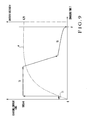
- Fig. 9 shows an example of the characteristics of the charging current of the battery 22 in Fig. 8 .
- the axis of ordinate represents a charging current ICHG or battery voltage V
- the axis of abscissa represents a charging time T.
- the charging circuit 21 is controlled to preliminarily charge the battery 22.
- the relationship between a voltage value (battery voltage) e of the battery 22 and the time is monitored to check if there is any abnormality. If the voltage value e satisfies a prescription value and charging of the battery 22 is normal, the charging process shifts to a quick charging period T 2 .
- the charging current ICHG of about 1,000 mA is supplied to the battery 22 to perform constant current driving. The charging voltage is thus quickly raised to near 4.2 V to perform charging.
- the charging process shifts to a trickle charging period T 3 .
- the charging current ICHG corresponding to the voltage difference between the AC adapter 10 and battery 22 is supplied to the battery 22 to perform constant current driving.
- the charging current also decreases.
- the charging current value is zero.
- an electromagnet is attached to a connector main body, and a metal piece to be attracted by the electromagnet is attached to a connector connection port.
- a switching circuit performs switching between energization and non-energization to the electromagnet on the basis of a control signal output from a portable terminal device main body.
- the portable telephone set described above has the following problems.
- the connector 9 and plug 13 are fitted with each other as the iron metal claws 13a of the plug 13 are fitted with the metal claw catches 9b of the connector 9.
- the operator pinches the metal claw release hooks 13b they disengage from the metal claw catches 9b, so that the plug 13 can be pulled out from connector 9.
- the iron metal claws 13a do not disengage from the metal claw catches 9b but are kept fixed by them. Then, the user may perform "twisting" operation to try to forcibly pull out the plug 13, undesirably damaging the connector 9 and plug 13.
- the plug 13 and notice tag 14 show notices concerning how to operate the metal claw release hooks 13b.
- This is insufficient as a radical countermeasure.
- people may often operate the metal claw release hooks 13b in a manner different from that practiced in Japan. Then, when pulling out the plug 13, the connector 9 or plug 13 may be damaged frequently.
- the present invention has been made in view of the above situation, and has as its object to provide an electronic device and a connector fitting method with which when disengaging a power supplying connector from an external device connecting connector, damages to the connectors are prevented.
- the present invention comprises an external device connecting connector which is connected to a power supplying connector of an external device having a power supplying function and receives power supplied from the external device, an electronic circuit which performs predetermined operation upon reception of the power supplied from the external device through the external device connecting connector, and an electromagnet which is provided to the external device connecting connector and electrically connected between the external device connecting connector and the electronic circuit, generates a magnetic force when a power supply current supplied from the external device flows therethrough, and attracts a predetermined portion formed of a magnetic body of the power supplying connector, to maintain a fitting state between the external device connecting connector and the power supplying connector.
- the present invention also comprises the step of fitting a power supplying connector of an external device having a power supplying function to an external device connecting connector of an electronic device which receives power from the external device, and the step of fitting the two connectors so that an electromagnet which is provided to the external device connecting connector and electrically connected between the external device connecting connector and the electronic circuit generates a magnetic force when a power supply current supplied from the external device flows to an electronic circuit of the external device, and attracts a predetermined portion formed of a magnetic body of the power supplying connector, thus maintaining a fitting state between the external device connecting connector and the power supplying connector.
- the external device connecting connector is provided with the electromagnet.
- the electromagnet When the power supply current supplied from the external device flows through the electromagnet, the electromagnet generates a magnetic force and attracts the magnetic body of the power supplying connector of the external device, thus maintaining the fitting state between the external device connecting connector and power supplying connector. Hence, the fitting state becomes reliable.
- the fitting state is canceled. Then, the power supplying connector can be pulled out from the external device connecting connector readily, so that damages can be prevented.
- Fig. 1 shows the electrical configuration of the main part of a portable telephone set 30 as first exemplary embodiment of the electronic device of the present invention.
- This portable telephone set 30 has a power supply unit (electronic circuit) 31, electromagnet 32, and connector (external device connecting connector) 33.
- the power supply unit 31 comprises a charging circuit 34 and battery 35 (rechargeable battery).
- the electromagnet is electrically connected in series between the connector 33 and power supply unit 31.
- the portable telephone set 30 is connected to an AC adapter 41 (an electronic device, a charging power supply device) through a plug (power supplying connector) 40.
- the AC adapter 41 has a function of supplying power to the portable telephone set 30.
- the connector 33 serves to receive power supplied from the AC adapter 41. Power is supplied from the AC adapter 41 to the power supply unit 31 of the portable telephone set 30 through a + terminal VCHG and ground terminal GND of the plug 40, the connector 33 of the portable telephone set 30, and a coil 32b of the electromagnet 32.
- the electromagnet 32 is formed by winding the coil 32b around a core 32a.
- the electromagnet 32 accompanies or is arranged in the vicinity of the connector 33.
- the electromagnet 32 When a power supply current supplied from the AC adapter 41 flows through the electromagnet 32, the electromagnet 32 generates a magnetic force. If a predetermined portion of the plug 40 is formed of a magnetic body (iron metal), the electromagnet 32 attracts the magnetic body, thus maintaining the fitted state with the connector 33.
- the charging circuit 34 receives power supplied from the AC adapter 41 through the connector 33 to charge the battery 35.
- the electromagnet 32 In a quick charging period T 2 in which the voltage difference between the voltage of the power supply and that of the battery 35 is a predetermined value or more, the electromagnet 32 is constant-current driven by the charging current ICHG having a predetermined current value. Thus, a constant fitting state is maintained between the plug 40 and connector 33.
- the charging circuit 34 drives the electromagnet 32 with the charging current ICHG having a current value corresponding to the voltage difference to gradually weaken the fitting state between the plug 40 and connector 33.
- the voltage difference disappears at a charging end point F, no charging current ICHG flows through the electromagnet 32.
- the plug 40 of the AC adapter 41 is provided with an iron metal portion (magnetic body) 40a at a predetermined portion.
- the connector 33 of the portable telephone set 30 has the iron metal case (magnetic body case) 33a which fits with the plug 40.
- the electromagnet 32 is arranged adjacent to the iron metal case 33a.
- the electromagnet 32 may be arranged at, e.g., that position on the connector 33 which opposes the iron metal portion 40a of the plug 40 when the connector 33 fits with the plug 40.
- Fig. 3 shows an example of the characteristics of the charging current of the battery 35 in Fig. 2 .
- the axis of ordinate represents a charging current ICHG or battery voltage V
- the axis of abscissa represents a charging time T.
- the processing content of the connector fitting method employed by the portable telephone set 30 will be described with reference to Fig. 3 .
- the electromagnet 32 when the power supply current supplied from the AC adapter 41 flows through the electromagnet 32, the electromagnet 32 generates a magnetic force to attract the iron metal portion 40a of the plug 40 of the AC adapter 41, so that the fitting state between the plug 40 and connector 33 is maintained.
- the charging circuit 34 is controlled to preliminarily charge the battery 35.
- the relationship between a voltage value (battery voltage) e of the battery 35 and the time is monitored to check if there is any abnormality. If the voltage value e satisfies a prescription value and charging of the battery 35 is normal, the charging process shifts to a quick charging period T 2 .
- the charging current ICHG of about 1,000 mA is supplied to the battery 35 to quickly raise the charging voltage to near 4.2 V to perform charging.
- the electromagnet 32 is driven by a constant current, and a constant fitting state is maintained between the plug 40 and connector 33.
- the charging process shifts to a trickle charging period T 3 .
- the charging current ICHG corresponding to the voltage difference between the AC adapter 41 and battery 35 is supplied to the battery 35.
- the electromagnet 32 is driven with a constant voltage.
- the charging current also decreases to gradually weaken the fitting state between the plug 40 and connector 33.
- the electromagnet 32 stops operation, thus canceling the fitting state between the plug 40 and connector 33.
- the value of the charging current ICHG at this time is zero.
- the magnetic force B is proportional to the number of turns of the coil 32b and the magnitude of the charging current ICHG.
- the electromagnet 32 is arranged adjacent to the iron metal case 33a of the connector 33.
- the power supply current supplied from the AC adapter 41 flows through the electromagnet 32.
- the electromagnet 32 generates the magnetic force to attract the iron metal portion 40a of the plug 40, thus maintaining the fitting state between the plug 40 and the connector 33.
- the electromagnet 32 stops operation, so that the fitting state between the plug 40 and connector 33 is canceled. Therefore, the plug 40 can be pulled out from the connector 33 readily, thus preventing damages.
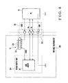
- Fig. 4 shows the electrical configuration of the main part of a portable telephone set 30A as the second exemplary embodiment of the electronic device of the present invention.
- elements that are common with those in Fig. 1 showing the first exemplary embodiment are denoted by the same reference numerals.
- the portable telephone set 30A is provided with, in place of the power supply unit 31 and connector 33 in Fig. 1 , a power supply unit (electronic circuit) 31A and connector (external device connecting connector) 33A having different arrangements.
- the connector 33A complies with the USB (Universal Serial Bus) standard.
- An electromagnet 32 is arranged adjacent to the connector 33A.
- the connector 33A is connected to a personal computer (PC) 51 as an external device through a plug 50 governed by the USB standard. That portion (not shown) of the plug (power supplying connector) 50 which is to fit with the connector 33A is made of an iron metal.
- the connector 33A serves to receive power from the personal computer 51.
- a power supply current IVBUS is supplied from the personal computer 51 to the power supply unit 31A of the portable telephone set 30A through a + terminal VBUS and ground terminal GND of the plug 50, the connector 33A of the portable telephone set 30A, and a coil 32b of the electromagnet 32.
- the power supply has a voltage of 5 V and a supply current of 100 mA or 500 mA.
- the power supply unit 31A has a USB circuit 36.
- the USB circuit 36 is operated by power supplied to it, and performs predetermined data communication with the personal computer 51 through terminals D+ and D- of the plug 50. Except for this, the configuration of Fig. 4 is the same as that of Fig. 1 .
- the electromagnet 32 is arranged adjacent to the connector 33A.
- the power supply current supplied from the personal computer 51 flows through the electromagnet 32.
- the electromagnet 32 generates the magnetic force to attract the fitting portion (iron metal) of the plug 50, thus maintaining the fitting state between the plug 50 and connector 33A.
- the electromagnet 32 stops operation so that the fitting state between the plug 50 and connector 33A is canceled. Therefore, the plug 50 can be pulled out from the connector 33 readily, thus preventing damages.
- the electromagnet 32 may be formed by winding the coil 32b around the iron metal case 33a in place of the core 32a in Fig. 2 . Then, magnetic fluxes are generated in the iron metal case 33a, which makes the fitting state with the plug 40 more reliable.
- the electronic devices are portable telephone sets.
- the electronic devices can be PDAs (Personal Digital Assistants) or the like.
- the iron metal case 33a of the connector 33 may suffice if it is formed such that the fitted plug 40 is attracted by the electromagnet 32.
- the iron metal case 33a may be made of a magnetic body, and can be made of a material such as a plastic material except for the modification in Fig. 5 .
- the housing of the portable telephone set is not limited to a folded type housing but can be, e.g., a slide type housing or straight type housing.
- the present invention can be applied to, in addition to portable telephone sets, electronic devices in general each of which has an external device connecting connector to receive power supplied from an external device having a power supplying function.
Landscapes
- Engineering & Computer Science (AREA)
- Microelectronics & Electronic Packaging (AREA)
- Charge And Discharge Circuits For Batteries Or The Like (AREA)
- Telephone Set Structure (AREA)
- Details Of Connecting Devices For Male And Female Coupling (AREA)
Abstract
Description
- This application is based upon and claims the benefit of priority from the prior Japanese Patent Application No.
2006-155426, filed June 2, 2006 - The present invention relates to an electronic device and a connector fitting method employed by the electronic device and, more particularly, to an electronic device and a connector fitting method which are suitably adopted when connecting a power supplying connector to an external device connecting connector.
- In a portable telephone set, when charging a rechargeable battery mounted in it, the power supplying connector of a charger is connected to an external device connecting connector. In recent years, the housing of the portable telephone set is becoming more compact and thinner than before. Accordingly, the connectors are also becoming compact and thin. The size and thickness of a connector tend to be inversely proportional to the physical strength of the connector. When inserting and pulling out the connectors, the connectors or their peripheral portions may be damaged. In view of this, countermeasures to prevent damages are taken by, e.g., changing the material of the connectors from a conventional plastic material to a metal.
- As an example of a portable telephone set of this type, for example, one shown in
Fig. 6 is available. - This
portable telephone set 1 has, e.g., a foldable housing, and comprises a unit 2,unit 3, andhinge 4, as shown inFig. 6 . The unit 2 comprises adisplay 5 andreceiver 6 on its front surface. Theunit 3 comprises a microphone 7 andoperation keys connector 9 on its end face, and incorporates a controller and rechargeable battery (not shown). Theunits 2 and 3 are folded through thehinge 4 such that their front surfaces oppose each other. - An
AC adapter 10 to charge the rechargeable battery is prepared as an accessory to theportable telephone set 1. TheAC adapter 10 is provided with an ACpower supply plug 11,cable 12,plug 13, andnotice tag 14. When charging, theplug 13 is connected to theconnector 9. Thenotice tag 14 describes notices concerning the attaching/detaching (inserting/pulling-out) operation of theplug 13. TheAC adapter 10 supplies power with a charging voltage of 4.2 V/1,000 mA that matches the standard of the rechargeable battery formed of, e.g., a lithium ion battery. - As shown in
Fig. 7 , theconnector 9 of theportable telephone set 1 has aniron metal case 9a. Theiron metal case 9a is provided withmetal claw catches 9b at predetermined portions. Theplug 13 of theAC adapter 10 is provided withiron metal claws 13a and metalclaw release hooks 13b. When fitting theconnector 9 and plug 13 with each other, theiron metal claws 13a of theplug 13 are fitted with themetal claw catches 9b of theconnector 9. Thus, theconnector 9 andplug 13 are reliably fitted with each other to ensure electrical characteristics. When pulling out theplug 13 from theconnector 9, the user pinches the metalclaw release hooks 13b, so that theiron metal claws 13a disengage from the metal claw catches 9b. - As shown in
Fig. 8 , theportable telephone set 1 has apower supply unit 20. Thepower supply unit 20 comprises acharging circuit 21 andbattery 22. Theportable telephone set 1 is connected to theAC adapter 10 through theplug 13 inFig. 6 . TheAC adapter 10 supplies power to thepower supply unit 20 of the portable telephone set 1 through a + terminal VCHG and ground terminal GND of theplug 13 and theconnector 9 of theportable telephone set 1. -
Fig. 9 shows an example of the characteristics of the charging current of thebattery 22 inFig. 8 . The axis of ordinate represents a charging current ICHG or battery voltage V, and the axis of abscissa represents a charging time T. - As shown in
Fig. 9 , during a preliminary charging period T1 immediately after the start of charging, thecharging circuit 21 is controlled to preliminarily charge thebattery 22. The relationship between a voltage value (battery voltage) e of thebattery 22 and the time is monitored to check if there is any abnormality. If the voltage value e satisfies a prescription value and charging of thebattery 22 is normal, the charging process shifts to a quick charging period T2. During the quick charging period T2, the charging current ICHG of about 1,000 mA is supplied to thebattery 22 to perform constant current driving. The charging voltage is thus quickly raised to near 4.2 V to perform charging. After that, when the voltage value e reaches near the rated value of 4.2 V, the charging process shifts to a trickle charging period T3. During the trickle charging period T3, the charging current ICHG corresponding to the voltage difference between theAC adapter 10 andbattery 22 is supplied to thebattery 22 to perform constant current driving. As the voltage difference gradually decreases, the charging current also decreases. When the voltage difference disappears at a point F, charging is completed. At this time, the charging current value is zero. - Other than the
portable telephone set 1 described above, as a related technique, for example, one described in reference 1 (Japanese Patent Laid-Open No.2005-045490 - According to the connector structure of the portable terminal device described in
reference 1, an electromagnet is attached to a connector main body, and a metal piece to be attracted by the electromagnet is attached to a connector connection port. A switching circuit performs switching between energization and non-energization to the electromagnet on the basis of a control signal output from a portable terminal device main body. - The portable telephone set described above has the following problems.
- In the
portable telephone set 1 shown inFig. 7 , theconnector 9 andplug 13 are fitted with each other as theiron metal claws 13a of theplug 13 are fitted with themetal claw catches 9b of theconnector 9. When the operator pinches the metalclaw release hooks 13b, they disengage from themetal claw catches 9b, so that theplug 13 can be pulled out fromconnector 9. At this time, if the user does not pull out theplug 13 correctly, theiron metal claws 13a do not disengage from the metal claw catches 9b but are kept fixed by them. Then, the user may perform "twisting" operation to try to forcibly pull out theplug 13, undesirably damaging theconnector 9 and plug 13. As a countermeasure against this, theplug 13 and noticetag 14 show notices concerning how to operate the metalclaw release hooks 13b. This, however, is insufficient as a radical countermeasure. Particularly, in foreign countries, people may often operate the metalclaw release hooks 13b in a manner different from that practiced in Japan. Then, when pulling out theplug 13, theconnector 9 orplug 13 may be damaged frequently. - In the connector structure of the portable terminal device described in
reference 1, switching takes place between energization/non-energization to the electromagnet on the basis of the control signal output from the portable terminal device main body. Although the object ofreference 1 is similar to that of the present invention, its configuration is different. - The present invention has been made in view of the above situation, and has as its object to provide an electronic device and a connector fitting method with which when disengaging a power supplying connector from an external device connecting connector, damages to the connectors are prevented.
- In order to solve the above problems, the present invention comprises an external device connecting connector which is connected to a power supplying connector of an external device having a power supplying function and receives power supplied from the external device, an electronic circuit which performs predetermined operation upon reception of the power supplied from the external device through the external device connecting connector, and an electromagnet which is provided to the external device connecting connector and electrically connected between the external device connecting connector and the electronic circuit, generates a magnetic force when a power supply current supplied from the external device flows therethrough, and attracts a predetermined portion formed of a magnetic body of the power supplying connector, to maintain a fitting state between the external device connecting connector and the power supplying connector.
- The present invention also comprises the step of fitting a power supplying connector of an external device having a power supplying function to an external device connecting connector of an electronic device which receives power from the external device, and the step of fitting the two connectors so that an electromagnet which is provided to the external device connecting connector and electrically connected between the external device connecting connector and the electronic circuit generates a magnetic force when a power supply current supplied from the external device flows to an electronic circuit of the external device, and attracts a predetermined portion formed of a magnetic body of the power supplying connector, thus maintaining a fitting state between the external device connecting connector and the power supplying connector.
- According to the present invention, the external device connecting connector is provided with the electromagnet. When the power supply current supplied from the external device flows through the electromagnet, the electromagnet generates a magnetic force and attracts the magnetic body of the power supplying connector of the external device, thus maintaining the fitting state between the external device connecting connector and power supplying connector. Hence, the fitting state becomes reliable. When supply of the power supply current from the external device is stopped, the fitting state is canceled. Then, the power supplying connector can be pulled out from the external device connecting connector readily, so that damages can be prevented.
-
-
Fig. 1 is a circuit diagram showing the electrical configuration of the main part of an electronic device according to the first exemplary embodiment of the present invention; -
Fig. 2 is a view showing the structures of the main parts of a connector and plug inFig. 1 ; -
Fig. 3 is a graph showing an example of the characteristics of the charging current of a battery inFig. 2 ; -
Fig. 4 is a circuit diagram showing the electrical configuration of the main part of a portable telephone set according to the second exemplary embodiment of the present invention; -
Fig. 5 is a view showing a modification of the arrangement of the connector inFig. 2 ; -
Fig. 6 is a perspective view showing an open state of a portable telephone set related to the present invention which has a foldable housing; -
Fig. 7 is a view showing the structures of the main parts of a connector and plug inFig. 6 ; -
Fig. 8 is a diagram showing the electrical configuration of the main part of the portable telephone set inFig. 6 and the AC adapter of the portable telephone set; and -
Fig. 9 is a graph showing an example of the characteristics of the charging current of a battery inFig. 8 . - The exemplary embodiments of the present invention will be described in detail with reference to the drawings.
-
Fig. 1 shows the electrical configuration of the main part of a portable telephone set 30 as first exemplary embodiment of the electronic device of the present invention. - This portable telephone set 30 has a power supply unit (electronic circuit) 31,
electromagnet 32, and connector (external device connecting connector) 33. Thepower supply unit 31 comprises a chargingcircuit 34 and battery 35 (rechargeable battery). The electromagnet is electrically connected in series between theconnector 33 andpower supply unit 31. The portable telephone set 30 is connected to an AC adapter 41 (an electronic device, a charging power supply device) through a plug (power supplying connector) 40. TheAC adapter 41 has a function of supplying power to the portable telephone set 30. Theconnector 33 serves to receive power supplied from theAC adapter 41. Power is supplied from theAC adapter 41 to thepower supply unit 31 of the portable telephone set 30 through a + terminal VCHG and ground terminal GND of theplug 40, theconnector 33 of the portable telephone set 30, and acoil 32b of theelectromagnet 32. - The
electromagnet 32 is formed by winding thecoil 32b around acore 32a. In particular, according to this exemplary embodiment, theelectromagnet 32 accompanies or is arranged in the vicinity of theconnector 33. When a power supply current supplied from theAC adapter 41 flows through theelectromagnet 32, theelectromagnet 32 generates a magnetic force. If a predetermined portion of theplug 40 is formed of a magnetic body (iron metal), theelectromagnet 32 attracts the magnetic body, thus maintaining the fitted state with theconnector 33. The chargingcircuit 34 receives power supplied from theAC adapter 41 through theconnector 33 to charge thebattery 35. In a quick charging period T2 in which the voltage difference between the voltage of the power supply and that of thebattery 35 is a predetermined value or more, theelectromagnet 32 is constant-current driven by the charging current ICHG having a predetermined current value. Thus, a constant fitting state is maintained between theplug 40 andconnector 33. In a trickle charging period T3 in which the voltage difference becomes smaller than the predetermined value, the chargingcircuit 34 drives theelectromagnet 32 with the charging current ICHG having a current value corresponding to the voltage difference to gradually weaken the fitting state between theplug 40 andconnector 33. When the voltage difference disappears at a charging end point F, no charging current ICHG flows through theelectromagnet 32. By utilizing these characteristics, supply of the charging current ICHG is stopped, thus canceling the fitted state. - As shown in
Fig. 2 , theplug 40 of theAC adapter 41 is provided with an iron metal portion (magnetic body) 40a at a predetermined portion. Theconnector 33 of the portable telephone set 30 has the iron metal case (magnetic body case) 33a which fits with theplug 40. Theelectromagnet 32 is arranged adjacent to theiron metal case 33a. Theelectromagnet 32 may be arranged at, e.g., that position on theconnector 33 which opposes theiron metal portion 40a of theplug 40 when theconnector 33 fits with theplug 40. -
Fig. 3 shows an example of the characteristics of the charging current of thebattery 35 inFig. 2 . The axis of ordinate represents a charging current ICHG or battery voltage V, and the axis of abscissa represents a charging time T. The processing content of the connector fitting method employed by the portable telephone set 30 will be described with reference toFig. 3 . - In the portable telephone set 30, when the power supply current supplied from the
AC adapter 41 flows through theelectromagnet 32, theelectromagnet 32 generates a magnetic force to attract theiron metal portion 40a of theplug 40 of theAC adapter 41, so that the fitting state between theplug 40 andconnector 33 is maintained. - More specifically, as shown in
Fig. 3 , during a preliminary charging period T1 immediately after the start of charging, the chargingcircuit 34 is controlled to preliminarily charge thebattery 35. The relationship between a voltage value (battery voltage) e of thebattery 35 and the time is monitored to check if there is any abnormality. If the voltage value e satisfies a prescription value and charging of thebattery 35 is normal, the charging process shifts to a quick charging period T2. During the quick charging period T2, the charging current ICHG of about 1,000 mA is supplied to thebattery 35 to quickly raise the charging voltage to near 4.2 V to perform charging. At this time, theelectromagnet 32 is driven by a constant current, and a constant fitting state is maintained between theplug 40 andconnector 33. After that, when the voltage value e reaches near the rated value of 4.2 V, the charging process shifts to a trickle charging period T3. During the trickle charging period T3, the charging current ICHG corresponding to the voltage difference between theAC adapter 41 andbattery 35 is supplied to thebattery 35. Simultaneously, theelectromagnet 32 is driven with a constant voltage. As the voltage difference gradually decreases, the charging current also decreases to gradually weaken the fitting state between theplug 40 andconnector 33. When the voltage difference disappears at a point F, charging is completed. At the same time, theelectromagnet 32 stops operation, thus canceling the fitting state between theplug 40 andconnector 33. The value of the charging current ICHG at this time is zero. - A magnetic force B generated by the
electromagnet 32 is expressed by the following equation (1) :
- µ: magnetic permeability,
- N: number of turns of the
coil 32b, - ICHG: charging current value,
- µ = µ0·µs,
- µ0: magnetic permeability of vacuum, and
- µs: specific magnetic permeability
- From equation (1), the magnetic force B is proportional to the number of turns of the
coil 32b and the magnitude of the charging current ICHG. - As described above, according to the first exemplary embodiment, the
electromagnet 32 is arranged adjacent to theiron metal case 33a of theconnector 33. During charging of thebattery 35, the power supply current supplied from theAC adapter 41 flows through theelectromagnet 32. Hence, theelectromagnet 32 generates the magnetic force to attract theiron metal portion 40a of theplug 40, thus maintaining the fitting state between theplug 40 and theconnector 33. After that, when charging is completed, theelectromagnet 32 stops operation, so that the fitting state between theplug 40 andconnector 33 is canceled. Therefore, theplug 40 can be pulled out from theconnector 33 readily, thus preventing damages. -
Fig. 4 shows the electrical configuration of the main part of a portable telephone set 30A as the second exemplary embodiment of the electronic device of the present invention. InFig. 4 , elements that are common with those inFig. 1 showing the first exemplary embodiment are denoted by the same reference numerals. - The portable telephone set 30A is provided with, in place of the
power supply unit 31 andconnector 33 inFig. 1 , a power supply unit (electronic circuit) 31A and connector (external device connecting connector) 33A having different arrangements. Theconnector 33A complies with the USB (Universal Serial Bus) standard. Anelectromagnet 32 is arranged adjacent to theconnector 33A. Theconnector 33A is connected to a personal computer (PC) 51 as an external device through aplug 50 governed by the USB standard. That portion (not shown) of the plug (power supplying connector) 50 which is to fit with theconnector 33A is made of an iron metal. Theconnector 33A serves to receive power from thepersonal computer 51. A power supply current IVBUS is supplied from thepersonal computer 51 to thepower supply unit 31A of the portable telephone set 30A through a + terminal VBUS and ground terminal GND of theplug 50, theconnector 33A of the portable telephone set 30A, and acoil 32b of theelectromagnet 32. On the basis of the specifications of the USB standard, the power supply has a voltage of 5 V and a supply current of 100 mA or 500 mA. Thepower supply unit 31A has aUSB circuit 36. TheUSB circuit 36 is operated by power supplied to it, and performs predetermined data communication with thepersonal computer 51 through terminals D+ and D- of theplug 50. Except for this, the configuration ofFig. 4 is the same as that ofFig. 1 . - In the portable telephone set 30A, the
electromagnet 32 is arranged adjacent to theconnector 33A. During data communication with thepersonal computer 51, the power supply current supplied from thepersonal computer 51 flows through theelectromagnet 32. Hence, theelectromagnet 32 generates the magnetic force to attract the fitting portion (iron metal) of theplug 50, thus maintaining the fitting state between theplug 50 andconnector 33A. After that, when communication is completed, theelectromagnet 32 stops operation so that the fitting state between theplug 50 andconnector 33A is canceled. Therefore, theplug 50 can be pulled out from theconnector 33 readily, thus preventing damages. - Although the exemplary embodiments of the present invention have been described in detail with reference to the drawings, the specific arrangement is not limited to those of the exemplary embodiments described above. Any design changes within the spirit and scope of the gist of the present invention is incorporated in the present invention.
- For example, as shown in
Fig. 5 , theelectromagnet 32 may be formed by winding thecoil 32b around theiron metal case 33a in place of thecore 32a inFig. 2 . Then, magnetic fluxes are generated in theiron metal case 33a, which makes the fitting state with theplug 40 more reliable. In the above exemplary embodiments, the electronic devices are portable telephone sets. Alternatively, the electronic devices can be PDAs (Personal Digital Assistants) or the like. Theiron metal case 33a of theconnector 33 may suffice if it is formed such that the fittedplug 40 is attracted by theelectromagnet 32. More specifically, theiron metal case 33a may be made of a magnetic body, and can be made of a material such as a plastic material except for the modification inFig. 5 . The housing of the portable telephone set is not limited to a folded type housing but can be, e.g., a slide type housing or straight type housing. - The present invention can be applied to, in addition to portable telephone sets, electronic devices in general each of which has an external device connecting connector to receive power supplied from an external device having a power supplying function.
Claims (10)
- An electronic device characterized by comprising:an external device connecting connector which is connected to a power supplying connector of an external device having a power supplying function and receives power supplied from said external device;an electronic circuit which performs predetermined operation upon reception of the power supplied from said external device through said external device connecting connector; andan electromagnet which is provided to said external device connecting connector and electrically connected between said external device connecting connector and said electronic circuit, generates a magnetic force when a power supply current supplied from said external device flows therethrough, and attracts a predetermined portion formed of a magnetic body of said power supplying connector, to maintain a fitting state between said external device connecting connector and said power supplying connector.
- An electronic device according to claim 1,
characterized in that
said electronic circuit comprises a rechargeable battery and a charging circuit to charge said rechargeable battery,
said external device comprises a charging power supply unit having a power supplying function to charge said rechargeable battery, and
when said charging circuit receives power supplied from said charging power supply device through said external device connecting connector to charge said rechargeable battery, during a quick charging period in which a voltage difference between a power supply and said rechargeable battery is not less than a predetermined value, said charging circuit drives said electromagnet with a charging current having a predetermined current value to maintain a constant fitting state between said power supplying connector and said external device connecting connector, during a trickle charging period in which the voltage difference becomes smaller than the predetermined value, said charging circuit drives said electromagnet with a charging current having a current value corresponding to the voltage difference to gradually weaken the fitting state between said power supplying connector and said external device connecting connector, and at charging end when the voltage difference disappears, said charging circuit stops supplying the charging current to cancel the fitting state. - An electronic device according to claim 1, characterized in that said electromagnet is provided to accompany said external device connecting connector.
- An electronic device according to claim 1, characterized in that said electromagnet is arranged in the vicinity of said external device connecting connector.
- An electronic device according to claim 1, characterized in that said electromagnet is arranged at a position on said external device connecting connector which opposes a predetermined portion formed of a magnetic body of said power supplying connector when said external device connecting connector and said power supplying connector are fitted with each other.
- An electronic device according to claim 1,
characterized in that
said external device connecting connector comprises a magnetic case which fits with said power supplying connector, and
said electromagnet comprises a coil which is wound around said magnetic case and through which a power supply current supplied from said external device flows. - An electronic device according to claim 1, characterized in that said external device connecting connector is governed by a USB standard.
- A connector fitting method characterized by comprising:the step of fitting a power supplying connector of an external device having a power supplying function to an external device connecting connector of an electronic device which receives power from the external device; andthe step of fitting the two connectors so that an electromagnet which is provided to the external device connecting connector and electrically connected between the external device connecting connector and the electronic circuit generates a magnetic force when a power supply current supplied from the external device flows to an electronic circuit of the external device, and attracts a predetermined portion formed of a magnetic body of the power supplying connector, thus maintaining a fitting state between the external device connecting connector and the power supplying connector.
- A connector fitting method according to claim 8, characterized in that the step of maintaining comprises
the step of driving the electromagnet with a charging current having a predetermined current value, during a quick charging period in which a voltage difference between a power supply and the rechargeable battery of an electronic circuit is not less than a predetermined value, to maintain a constant fitting state between the power supplying connector and the external device connecting connector, and
the step of driving the electromagnet with a charging current having a current value corresponding to the voltage difference, during a trickle charging period in which the voltage difference becomes smaller than the predetermined value, to gradually weaken the fitting state between the power supplying connector and the external device connecting connector. - A connector fitting method according to claim 9, further comprising the step of stopping supplying the charging current to the electromagnet, at charging end when the voltage difference disappears, to cancel the fitting state.
Applications Claiming Priority (2)
| Application Number | Priority Date | Filing Date | Title |
|---|---|---|---|
| JP2006155426 | 2006-06-02 | ||
| PCT/JP2007/060793 WO2007142060A1 (en) | 2006-06-02 | 2007-05-28 | Electronic device and connector fitting method |
Publications (2)
| Publication Number | Publication Date |
|---|---|
| EP2026441A1 true EP2026441A1 (en) | 2009-02-18 |
| EP2026441A4 EP2026441A4 (en) | 2017-04-12 |
Family
ID=38801320
Family Applications (1)
| Application Number | Title | Priority Date | Filing Date |
|---|---|---|---|
| EP07744227.5A Withdrawn EP2026441A4 (en) | 2006-06-02 | 2007-05-28 | Electronic device and connector fitting method |
Country Status (5)
| Country | Link |
|---|---|
| US (1) | US8198861B2 (en) |
| EP (1) | EP2026441A4 (en) |
| JP (1) | JP5176955B2 (en) |
| CN (1) | CN101461117B (en) |
| WO (1) | WO2007142060A1 (en) |
Cited By (3)
| Publication number | Priority date | Publication date | Assignee | Title |
|---|---|---|---|---|
| DE102009022886A1 (en) * | 2009-05-27 | 2010-12-02 | Bayerische Motoren Werke Aktiengesellschaft | Device for the mechanical and electrical connection of a portable, battery-operated device and portable, battery-powered device |
| US8351178B2 (en) | 2010-09-15 | 2013-01-08 | Transcend Information, Inc. | Electronic system with secured data accessing |
| CN103259313A (en) * | 2013-05-26 | 2013-08-21 | 苏州快可光伏电子股份有限公司 | Locking structure for automobile charging connection system |
Families Citing this family (15)
| Publication number | Priority date | Publication date | Assignee | Title |
|---|---|---|---|---|
| US8388353B2 (en) | 2009-03-11 | 2013-03-05 | Cercacor Laboratories, Inc. | Magnetic connector |
| CN201774463U (en) * | 2010-06-14 | 2011-03-23 | 鸿富锦精密工业(深圳)有限公司 | energy-saving adapter |
| CN102202117B (en) * | 2011-04-22 | 2015-01-28 | 中兴通讯股份有限公司 | Electronic device with USB (universal serial bus) interface and USB communication starting method thereof |
| WO2013132558A1 (en) * | 2012-03-09 | 2013-09-12 | パナソニック株式会社 | Ac adaptor |
| JP2015077021A (en) * | 2013-10-10 | 2015-04-20 | ソニー株式会社 | Power reception device and power transmission unit and power supply system |
| KR101412679B1 (en) * | 2013-11-08 | 2014-06-27 | (주)에스피에스 | A power supply system having a magnetic connector |
| US9739818B2 (en) | 2014-03-12 | 2017-08-22 | The Boeing Company | Electromagnetic effect testing |
| US9767949B2 (en) * | 2015-06-15 | 2017-09-19 | Sony Corporation | Controlling of a magnetic connection between an electrical device and a cable |
| CN105245647A (en) * | 2015-10-09 | 2016-01-13 | 小米科技有限责任公司 | Card slot automatic ejection device and electronic equipment |
| WO2017117730A1 (en) * | 2016-01-05 | 2017-07-13 | 广东欧珀移动通信有限公司 | Rapid charging method, mobile terminal and adapter |
| US10432002B2 (en) * | 2016-03-08 | 2019-10-01 | Arian Shoari | Apparatus and methods for sustainable battery charging |
| CN106785686A (en) * | 2016-12-13 | 2017-05-31 | 普天新能源(深圳)有限公司 | Charging gun release circuit and charging gun |
| US10283952B2 (en) | 2017-06-22 | 2019-05-07 | Bretford Manufacturing, Inc. | Rapidly deployable floor power system |
| CN110336901B (en) * | 2019-06-28 | 2021-04-27 | 维沃移动通信有限公司 | Mobile terminal and external equipment |
| CN113224468B (en) * | 2021-07-08 | 2021-09-17 | 南京华测检测有限公司 | Group battery that plant protection equipment used and charging device thereof |
Family Cites Families (15)
| Publication number | Priority date | Publication date | Assignee | Title |
|---|---|---|---|---|
| JPS61170243A (en) | 1985-01-24 | 1986-07-31 | 松下電器産業株式会社 | Charging device for pack battery |
| JPH0553013U (en) * | 1991-12-18 | 1993-07-13 | 株式会社小糸製作所 | Vehicle lighting |
| JPH0566605U (en) * | 1992-02-12 | 1993-09-03 | 日本電気株式会社 | Optical cable connector |
| JPH07272794A (en) * | 1994-03-31 | 1995-10-20 | Mitsubishi Electric Corp | Connector device |
| JPH10225000A (en) * | 1997-01-31 | 1998-08-21 | Sanyo Electric Co Ltd | Charger for cordless telephone and child telephone |
| US6616468B2 (en) * | 2000-04-17 | 2003-09-09 | Fujikura Ltd. | Connector and electric connection structure |
| DE10056410A1 (en) | 2000-11-14 | 2002-05-23 | Daimler Chrysler Ag | Electrical pluggable connection, uses magnetic armature to latch inter-plugged parts in locking position |
| JP2002354678A (en) * | 2001-05-29 | 2002-12-06 | Canon Inc | Power generation device and control method thereof |
| JP3829927B2 (en) * | 2001-11-30 | 2006-10-04 | Necトーキン株式会社 | Charger |
| US6875035B2 (en) * | 2001-12-18 | 2005-04-05 | Fujikura Ltd. | Connector and electric connection structure |
| JP2005045490A (en) * | 2003-07-28 | 2005-02-17 | Kyocera Corp | Connector structure of portable terminal equipment |
| JP4520836B2 (en) | 2004-11-30 | 2010-08-11 | 三機工業株式会社 | Intrusion detection device |
| US7775801B2 (en) * | 2005-01-05 | 2010-08-17 | Microsoft Corporation | Device interfaces with non-mechanical securement mechanisms |
| US7351066B2 (en) * | 2005-09-26 | 2008-04-01 | Apple Computer, Inc. | Electromagnetic connector for electronic device |
| US7311526B2 (en) * | 2005-09-26 | 2007-12-25 | Apple Inc. | Magnetic connector for electronic device |
-
2007
- 2007-05-28 CN CN200780020401.1A patent/CN101461117B/en active Active
- 2007-05-28 EP EP07744227.5A patent/EP2026441A4/en not_active Withdrawn
- 2007-05-28 WO PCT/JP2007/060793 patent/WO2007142060A1/en not_active Ceased
- 2007-05-28 JP JP2008520497A patent/JP5176955B2/en not_active Expired - Fee Related
- 2007-05-28 US US12/303,142 patent/US8198861B2/en not_active Expired - Fee Related
Non-Patent Citations (1)
| Title |
|---|
| See references of WO2007142060A1 * |
Cited By (5)
| Publication number | Priority date | Publication date | Assignee | Title |
|---|---|---|---|---|
| DE102009022886A1 (en) * | 2009-05-27 | 2010-12-02 | Bayerische Motoren Werke Aktiengesellschaft | Device for the mechanical and electrical connection of a portable, battery-operated device and portable, battery-powered device |
| US8362743B2 (en) | 2009-05-27 | 2013-01-29 | Bayerische Motoren Werke Aktiengesellschaft | Device for mechanically and electrically connecting a portable, battery-operated apparatus and portable, battery-operated apparatus |
| US8351178B2 (en) | 2010-09-15 | 2013-01-08 | Transcend Information, Inc. | Electronic system with secured data accessing |
| CN103259313A (en) * | 2013-05-26 | 2013-08-21 | 苏州快可光伏电子股份有限公司 | Locking structure for automobile charging connection system |
| CN103259313B (en) * | 2013-05-26 | 2016-08-03 | 苏州快可光伏电子股份有限公司 | A kind of locking mechanism of vehicle charging connection system |
Also Published As
| Publication number | Publication date |
|---|---|
| CN101461117B (en) | 2014-04-23 |
| JP5176955B2 (en) | 2013-04-03 |
| EP2026441A4 (en) | 2017-04-12 |
| WO2007142060A1 (en) | 2007-12-13 |
| CN101461117A (en) | 2009-06-17 |
| US8198861B2 (en) | 2012-06-12 |
| JPWO2007142060A1 (en) | 2009-10-22 |
| US20090206800A1 (en) | 2009-08-20 |
Similar Documents
| Publication | Publication Date | Title |
|---|---|---|
| US8198861B2 (en) | Electronic device and connector fitting method | |
| EP2278668B1 (en) | Power supply device, portable electronic apparatus and related method for determining types of a power supply device | |
| CN101399383B (en) | adaptive battery holder, battery recharging system including the same, and battery recharging method using the same | |
| EP1770606B1 (en) | Charging apparatus and charging system | |
| US6115277A (en) | Battery charger adapter for military vehicles | |
| US9153983B2 (en) | Charging device | |
| US20100201308A1 (en) | Device and method for battery charging | |
| US20110089889A1 (en) | Battery charger for portable devices and related methods | |
| WO2010055576A1 (en) | Charging circuit, electronic device, program, charging method and power supply device | |
| EP2071428A2 (en) | Method and arrangement for controlling an electrical device | |
| US20130049681A1 (en) | Charging device and charging system | |
| CN102044895B (en) | Battery state monitoring circuit and battery device | |
| US11662396B2 (en) | Power receiving apparatus, control method, and storage medium | |
| EP2783426B1 (en) | An electrical device | |
| US20160365185A1 (en) | Controlling of a magnetic connection between an electrical device and a cable | |
| EP2115848A1 (en) | System and method for recharging a mobile submersible device | |
| CN112821491B (en) | A mobile phone charger with high safety | |
| JP2014060861A (en) | Charger for secondary battery | |
| CN212275920U (en) | UPS power supply discharge detection device and system | |
| CN114220369A (en) | Driving circuit, driving method and display terminal | |
| EP1601092A2 (en) | Universal configurable multiple power supply | |
| CN112117810B (en) | A charging circuit and charging method suitable for a hybrid charger | |
| CN108494037A (en) | Battery pack maintenance protection circuit and battery pack | |
| CN118281651A (en) | Charging cable, charging device, and data transmission and charging method | |
| JPH06138979A (en) | Portable terminal |
Legal Events
| Date | Code | Title | Description |
|---|---|---|---|
| PUAI | Public reference made under article 153(3) epc to a published international application that has entered the european phase |
Free format text: ORIGINAL CODE: 0009012 |
|
| 17P | Request for examination filed |
Effective date: 20081124 |
|
| AK | Designated contracting states |
Kind code of ref document: A1 Designated state(s): AT BE BG CH CY CZ DE DK EE ES FI FR GB GR HU IE IS IT LI LT LU LV MC MT NL PL PT RO SE SI SK TR |
|
| AX | Request for extension of the european patent |
Extension state: AL BA HR MK RS |
|
| DAX | Request for extension of the european patent (deleted) | ||
| RBV | Designated contracting states (corrected) |
Designated state(s): DE FR GB IT |
|
| RAP1 | Party data changed (applicant data changed or rights of an application transferred) |
Owner name: LENOVO INNOVATIONS LIMITED (HONG KONG) |
|
| RA4 | Supplementary search report drawn up and despatched (corrected) |
Effective date: 20170310 |
|
| RIC1 | Information provided on ipc code assigned before grant |
Ipc: H02J 7/00 20060101AFI20170306BHEP Ipc: H01R 13/62 20060101ALI20170306BHEP Ipc: H01R 13/713 20060101ALI20170306BHEP Ipc: H01R 13/66 20060101ALI20170306BHEP Ipc: H04M 1/02 20060101ALI20170306BHEP Ipc: H04B 7/26 20060101ALI20170306BHEP |
|
| STAA | Information on the status of an ep patent application or granted ep patent |
Free format text: STATUS: EXAMINATION IS IN PROGRESS |
|
| 17Q | First examination report despatched |
Effective date: 20180126 |
|
| GRAP | Despatch of communication of intention to grant a patent |
Free format text: ORIGINAL CODE: EPIDOSNIGR1 |
|
| STAA | Information on the status of an ep patent application or granted ep patent |
Free format text: STATUS: GRANT OF PATENT IS INTENDED |
|
| RIC1 | Information provided on ipc code assigned before grant |
Ipc: H01R 13/66 20060101ALI20180326BHEP Ipc: H04M 1/02 20060101ALN20180326BHEP Ipc: H01R 13/713 20060101ALI20180326BHEP Ipc: H04B 7/26 20060101ALI20180326BHEP Ipc: H01R 13/62 20060101AFI20180326BHEP |
|
| INTG | Intention to grant announced |
Effective date: 20180418 |
|
| STAA | Information on the status of an ep patent application or granted ep patent |
Free format text: STATUS: THE APPLICATION IS DEEMED TO BE WITHDRAWN |
|
| 18D | Application deemed to be withdrawn |
Effective date: 20180829 |