EP2026368A1 - Distribution of the space for switch apparatuses - Google Patents
Distribution of the space for switch apparatuses Download PDFInfo
- Publication number
- EP2026368A1 EP2026368A1 EP06755350A EP06755350A EP2026368A1 EP 2026368 A1 EP2026368 A1 EP 2026368A1 EP 06755350 A EP06755350 A EP 06755350A EP 06755350 A EP06755350 A EP 06755350A EP 2026368 A1 EP2026368 A1 EP 2026368A1
- Authority
- EP
- European Patent Office
- Prior art keywords
- housing
- section
- current path
- region
- sections
- Prior art date
- Legal status (The legal status is an assumption and is not a legal conclusion. Google has not performed a legal analysis and makes no representation as to the accuracy of the status listed.)
- Granted
Links
Images
Classifications
-
- H—ELECTRICITY
- H01—ELECTRIC ELEMENTS
- H01H—ELECTRIC SWITCHES; RELAYS; SELECTORS; EMERGENCY PROTECTIVE DEVICES
- H01H71/00—Details of the protective switches or relays covered by groups H01H73/00 - H01H83/00
- H01H71/02—Housings; Casings; Bases; Mountings
- H01H71/0207—Mounting or assembling the different parts of the circuit breaker
-
- H—ELECTRICITY
- H01—ELECTRIC ELEMENTS
- H01H—ELECTRIC SWITCHES; RELAYS; SELECTORS; EMERGENCY PROTECTIVE DEVICES
- H01H71/00—Details of the protective switches or relays covered by groups H01H73/00 - H01H83/00
- H01H71/002—Details of the protective switches or relays covered by groups H01H73/00 - H01H83/00 with provision for switching the neutral conductor
Definitions
- the present disclosure relates generally to switching devices, and particularly to circuit breakers.
- circuit breakers Extensive use of circuit breakers has promoted the development of standardized circuit breaker housing dimensions. For example, it is common that single pole circuit breakers sold in Europe for residential and/or lighting applications are contained within housings that are 18 millimeters wide. Similarly, it is common that single pole circuit breakers sold in the US for residential and/or lighting applications are contained within housings that are 0.75 inches wide.
- With careful allocation of the internal space it is possible to increase the number of circuit protection devices within a housing of given envelope dimensions. For example, many modules having the standardized envelope dimensions to incorporate a single power pole now additionally include protection for a neutral pole. Further, modules that have two active power poles within the standard housing dimensions for a single pole breaker have been developed.
- Multi-sectional housings may include a partition surface that provides a lateral division within the housing, preferably in the middle to provide an equal volume distribution.
- Other allocation methods have been developed that may provide unequal volume distributions. Space constraints within the housing may have functional effects upon the devices contained therein. Accordingly, the art may be advanced by an optimized space arrangement within a circuit breaker.
- An embodiment of the invention includes a housing for a single-pole circuit breaker.
- the housing includes two current path regions, each region having a first section configured to receive an electromagnetic protection device, a second section configured to receive a thermal protection device, a third section configured to receive an arc extinguishing device, and a fourth section configured to receive an operating mechanism device.
- Each first section occupies a substantial part of the available internal width of the housing, and is disposed between the respective third and fourth sections.
- Each second section occupies about half the available internal width of the housing.
- the housing includes two current path regions, each region comprising a first section configured to receive an electromagnetic protection device, a second section configured to receive a thermal protection device, a third section configured to receive an arc extinguishing device, and a fourth section configured to receive an operating mechanism device.
- the circuit breaker further includes two electromagnetic protection devices, each disposed within the first section of each current path region, two thermal protection devices, each disposed within the second section of each current path region, two arc extinguishing devices, each disposed within the third section of each current path region, each device defining a portion of the current path within each current path region.
- An operating mechanism device is disposed within the fourth section of each current path region, configured to open and close the current path of each current path region.
- Each first section occupies a substantial part of the available internal width of the housing and is disposed between the respective third and fourth sections.
- Each second section occupies about half the available internal width of the housing.
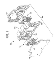
- Figure 1 depicts a top perspective exploded view of a circuit breaker in accordance with an embodiment of the invention
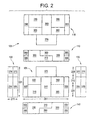
- Figure 2 depicts a six view orthographic layout of a circuit breaker housing in accordance with an embodiment of the invention
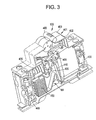
- Figure 3 depicts a side perspective internal view of a circuit breaker, in accordance with an embodiment of the invention.
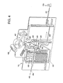
- Figure 4 depicts a side perspective of the circuit breaker of Figure 3 with some parts removed for clarity, in accordance with an embodiment of the invention
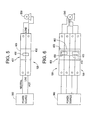
- Figure 5 depicts a schematic circuit diagram of a circuit breaker connection arrangement in accordance with an embodiment of the invention.
- Figure 6 depicts a schematic circuit diagram of a circuit breaker connection arrangement in accordance with an embodiment of the invention.
- An embodiment of the invention provides a single-pole circuit breaker with two current path regions.
- the circuit breaker has envelope dimensions meeting the standards for circuit breakers with one pole, with an equal utilization of the internal space for each current path region.
- Each current path region within the circuit breaker includes both thermal and electromagnetic protection devices.
- the circuit breaker accommodates two coils to provide electromagnetic protection, one coil for each current path region.
- each coil has a round cross-section that consumes all or substantially all of the available internal width of the single-pole circuit breaker housing.
- An embodiment of the invention provides two bimetallic strips for thermal protection, one bimetal for each current path region, and two arc chambers, one for each current path region, to extinguish any arcs generated during breaker activation.
- An embodiment of the invention is configured to provide double protection to a single circuit.
- Another embodiment of the invention is configured to provide full protection to a three-phase circuit, or a three-phase circuit with switching neutral.
- FIG. 1 an exploded assembly view of an exemplary embodiment of a circuit breaker 100 is depicted.
- Two sides 106, 107, and a center 108 collectively form a circuit breaker housing 105.
- the circuit breaker housing 105 includes two current path regions 160, 170 to provide space and support for two circuit protection devices 161, 171, which will be described in more detail below.
- the circuit breaker housing 105 has dimensions that are the same as standardized single-pole circuit breakers 100, such as 18 millimeters wide in Europe and 0.75 inches wide in the US, for example.
- two current path regions 160, 170 are contained within one of the circuit breaker housing 105.
- FIG. 2 an illustration of the internal space layout of the exemplary circuit breaker housing 105 is depicted in a six-view orthographic projection. Each view is divided into sections configured to receive portions of the devices 161, 171 for a circuit breaker 100.
- a first side view 101, top view 110, second side view 115, left view 120, right view 130, and bottom view 140 of the circuit breaker housing 105 are depicted utilizing third angle projection.
- a length, width, and height of the circuit breaker housing 105 are identified by reference numerals 201, 211, and 221, respectively.
- the circuit breaker 100 may be broken into a top zone 200, middle zone 210, and bottom zone 220 which will assist in describing the allocation of space within the circuit breaker 100.
- the top view 110 and bottom view 140 indicate essentially the division of space within the middle zone 210 and bottom zone 220. Details regarding the specific devices 161, 171 within each section will be discussed further below.
- An actuator 400 is in mechanical communication with an operating mechanism device (also herein referred to as a mechanism) 401 to control the position of a movable contact arm 405 about a pivot pin 406.
- reference numeral 401 may refer to either a first 402 portion or a second portion 403 of the mechanism 401 in conjunction with each individual circuit protection device 161, 171.
- the operating mechanism 401 is configured and disposed via first and second portions 402, 403 so as to provide a "common trip" function, to allow both circuit protection devices 161, 171 to trip together in response to a trip event in either circuit protection device 161, 171.
- the actuator 400 is configured to allow manual opening and closing of the current path in the first and second current path regions 160, 170 together.
- an arc extinguishing device (also herein referred to as an arc chute) 450, may, and is allowed to, consume a substantial portion of the full internal width 211 of the circuit breaker 100, and extinguishes arcs that may be created during a trip event of the circuit breaker 100.
- a thermal protection device (also herein referred to as a bimetallic strip) 445 may consume up to about half of the circuit breaker 100 internal width 211, and provides circuit protection via thermal trip action.
- An electromagnetic protection device (also herein referred to as a coil) 435 may, and is allowed to, consume a substantial portion of the full internal width 211 of the circuit breaker 100, and provide circuit protection via electromagnetic trip action.
- a first circuit connection 465 is associated with the coil 435, and a second circuit connection 430 is associated with the bimetallic strip 445, the circuit connections 465, 430 configured to allow for power connections to the circuit breaker 100. It will be appreciated that although it is not visible in the perspective of Figure 3 , the circuit breaker 100 will utilize a second contact arm 405, arc chute 450, bimetallic strip 445, coil 435, first circuit connection 465, and second circuit connection 430 for the other current path region 170, which is located behind (into the paper) the plane depicted in Figure 3 .
- a current path 460 through an exemplary embodiment of the circuit protection device 161, disposed in the current path region 160 of the circuit breaker housing 105 is depicted.
- Current is supplied via a line conductor 464 in power connection with the first circuit connection 465, (which is best seen in reference to Figure 3 ) which is connected to the coil 435.
- the coil 435 is in power connection with a contact holder 436 upon which a fixed contact 416 is disposed.
- Current will then flow from the fixed contact 416 to a movable contact 415 disposed upon the contact arm 405.
- Current will then flow through the contact arm 405, through conductor 408 and to the bimetallic strip 445.
- reference numeral 500 may refer to any appropriate electrical load, such as a lighting fixture, one-phase, or three-phase motor, for example.
- the contact arm 405 in Figure 4 is depicted in a CLOSED position, to allow current flow through the current path 460. It will be appreciated that in response to a counter-clockwise rotation of the contact arm 405 about the pivot 406, a mechanical and electrical separation between fixed contact 416 and movable contact 415 will result, thereby defining an OPEN position to interrupt the flow of current.
- the actuator 400 is in mechanical connection with the mechanism 401 that controls the position of the contact arm 405 in a manner known in the art.
- the mechanism 401 In response to the actuator 400 being moved to an ON position, the mechanism 401 will cause the contact arm 405 to rotate in a clockwise direction about the pivot 406, providing mechanical and electrical connection between the fixed contact 416, and the movable contact 415, creating the CLOSED current path 460.
- the mechanism 401 in response to the actuator 400 being moved to an OFF position, the mechanism 401 will cause the contact arm 405 to rotate in a counter clockwise direction about pivot 406, separating the mechanical and electrical connection between the fixed contact 416 and the movable contact 415, creating an OPEN current path 460, thereby preventing the flow of current within the current path 460.
- circuit protection device depicting a single contact arrangement utilizing a contact arm with one movable contact to interrupt current via rotary motion
- the scope of the invention is not so limited, and that the invention also applies to other methods to interrupt current flow, such as contact arms that may utilize linear motion, or alternate contact arrangements, such as double contacts, for example.
- contact arms that may utilize linear motion, or alternate contact arrangements, such as double contacts, for example.
- an exemplary embodiment has been described depicting an arc extinguishing device with one arc chute, it will be appreciated that the scope of the invention is not so limited, and that the invention also applies to other arc extinguishing arrangements, such as an extinguishing device with two arc chutes, for example.
- the circuit breaker 100 provides electromagnetic circuit protection via the coil 435.
- the coil 435 is configured to activate the mechanism 401, which, in turn, will rotate the contact arm 405 to the OPEN position, thereby interrupting the current path 460 to prevent any subsequent current flow.
- the circuit breaker 100 provides thermal protection via the bimetallic strip 445. As current flows through the bimetallic strip 445, heating will occur as a result of the material resistance. This heating will cause a defined displacement at the free end of the bimetallic strip 445.
- the displacement of the bimetallic strip 445 will activate the mechanism 401 to rotate the contact arm 405 to the OPEN position, thereby interrupting the current path 460.
- the opening action via the coil or bimetal due to an overcurrent condition is referred to as a trip action.
- the bimetallic strip 445 depicted in the exemplary embodiment of Figure 4 depicts the conductors 408, 409 arranged so as to allow the current to flow through the length of the bimetallic contact, which is known in the art as a "direct heating” arrangement. It will be appreciated by one skilled in the art that alternate methods of conductor 408, 409 connection may be employed, such as "indirect heating", whereby the conductors 408, 409 are both attached at the end opposite the free end such that the length of current flow is comparatively short, and the resulting heat is transferred via thermal conduction within the bimetallic strip 445.
- circuit protection device 161 While an exemplary embodiment has been described with current flow through circuit protection device 161 in a first direction, it will be appreciated that scope of the invention is not so limited, and that the invention also applies to a circuit protection device through which current may flow in the opposite direction. While the current path has been described for one circuit protection device 161, it will be appreciated that an exemplary embodiment of the invention employs two similar circuit protection devices 161, 171, as depicted in Figure 1 for example.
- circuit breaker 100 is configured to provide double circuit protection to the load 500 as connected to a power supply 550.
- FIG. 6 a schematic circuit utilizing an exemplary embodiment of the circuit breaker 100 is depicted.
- two circuit breakers 100 are configured to provide complete circuit protection to a three-phase load 510 as connected to a three-phase power supply 560, depicted in Figure 6 with a switching neutral.
- An optional actuator tie 410 may be utilized to synchronize the application and removal of power to the circuit.
- the circuit interruption devices 161, 171 have been configured to allow configuration of the circuit breaker housing 105 to provide current path regions 160, 170 that occupy the same amount of internal volume. Within each current path region 160, 170, six sections are configured to receive each individual component of each of the circuit interruption devices 161, 171. Referring now to Figure 2 in conjunction with Figure 4 , in an embodiment, a first section 300, 350 for each current path region 160, 170, respectively, is configured to receive the coil 435 of the circuit interruption devices 161, 171. A second section 310, 360 is configured to receive the bimetallic strip 445. A third section 315, 365 is configured to receive the arc chute 450.
- a fourth section 375, 376 is configured to receive the mechanism 401.
- a fifth section 305, 355 is configured to receive the first circuit connection 465, and a sixth section 306, 356 is configured to receive the second circuit connection 430. It will be appreciated that as a result of the mirror arrangement of the devices 161, 171 within the housing 105 that each fifth section 305, 355 is diagonally opposed (disposed at opposing ends of the housing 105 relative to the length 201 and width 211 of the housing 105). Similarly, each sixth section 306, 356 is diagonally opposed.
- each first section 300, 350 shall occupy a substantial portion of the circuit breaker housing 105 width 211, and be disposed between the respective third sections 315, 365 and the fourth sections 375, 376. Further, each first section 300, 350 shall be disposed between the respective second sections 310, 360 and the fifth sections 305, 355.
- the term "substantial" represents all of the functionally useful internal width considering the size and geometry of the coil 435.
- each second section 310, 360 shall occupy about half the width 211 of the circuit breaker housing 105, and be disposed between the respective first sections 300, 350 and sixth sections 306, 356. Further, each second section 310, 360 shall be centrally disposed within the circuit breaker housing 105 relative to the length 201 of the housing 105, and shall be side by side each other relative to the width 211 of the housing 105. Each third section 315, 365 shall occupy a substantial part of the available internal width 211 of the housing 105, and be disposed at opposing sides relative to the circuit breaker housing 105 length 201 between the respective second sections 310, 360 and fifth sections 305, 355. As used herein, the term "about" represents a minimum deviation that may result from manufacturing and material tolerances, for example.
- some embodiments of the invention may include some of the following advantages: double thermal and electromagnetic circuit protection in a compact housing; the ability to utilize two coils of circular cross section, each configured to fit the entire internal housing width; and, the ability to divide internal volume equally within a housing.
Landscapes
- Breakers (AREA)
Abstract
Description
- The present disclosure relates generally to switching devices, and particularly to circuit breakers. Extensive use of circuit breakers has promoted the development of standardized circuit breaker housing dimensions. For example, it is common that single pole circuit breakers sold in Europe for residential and/or lighting applications are contained within housings that are 18 millimeters wide. Similarly, it is common that single pole circuit breakers sold in the US for residential and/or lighting applications are contained within housings that are 0.75 inches wide. With careful allocation of the internal space, it is possible to increase the number of circuit protection devices within a housing of given envelope dimensions. For example, many modules having the standardized envelope dimensions to incorporate a single power pole now additionally include protection for a neutral pole. Further, modules that have two active power poles within the standard housing dimensions for a single pole breaker have been developed. Multi-sectional housings may include a partition surface that provides a lateral division within the housing, preferably in the middle to provide an equal volume distribution. Other allocation methods have been developed that may provide unequal volume distributions. Space constraints within the housing may have functional effects upon the devices contained therein. Accordingly, the art may be advanced by an optimized space arrangement within a circuit breaker.
- An embodiment of the invention includes a housing for a single-pole circuit breaker. The housing includes two current path regions, each region having a first section configured to receive an electromagnetic protection device, a second section configured to receive a thermal protection device, a third section configured to receive an arc extinguishing device, and a fourth section configured to receive an operating mechanism device. Each first section occupies a substantial part of the available internal width of the housing, and is disposed between the respective third and fourth sections. Each second section occupies about half the available internal width of the housing.
- Another embodiment of the invention includes a circuit breaker with a single-pole housing. The housing includes two current path regions, each region comprising a first section configured to receive an electromagnetic protection device, a second section configured to receive a thermal protection device, a third section configured to receive an arc extinguishing device, and a fourth section configured to receive an operating mechanism device. The circuit breaker further includes two electromagnetic protection devices, each disposed within the first section of each current path region, two thermal protection devices, each disposed within the second section of each current path region, two arc extinguishing devices, each disposed within the third section of each current path region, each device defining a portion of the current path within each current path region. An operating mechanism device is disposed within the fourth section of each current path region, configured to open and close the current path of each current path region. Each first section occupies a substantial part of the available internal width of the housing and is disposed between the respective third and fourth sections. Each second section occupies about half the available internal width of the housing.
- Referring to the exemplary drawings wherein like elements are numbered alike in the accompanying Figures:
-
Figure 1 depicts a top perspective exploded view of a circuit breaker in accordance with an embodiment of the invention; -
Figure 2 depicts a six view orthographic layout of a circuit breaker housing in accordance with an embodiment of the invention; -
Figure 3 depicts a side perspective internal view of a circuit breaker, in accordance with an embodiment of the invention; -
Figure 4 depicts a side perspective of the circuit breaker ofFigure 3 with some parts removed for clarity, in accordance with an embodiment of the invention; -
Figure 5 depicts a schematic circuit diagram of a circuit breaker connection arrangement in accordance with an embodiment of the invention; and -
Figure 6 depicts a schematic circuit diagram of a circuit breaker connection arrangement in accordance with an embodiment of the invention. - An embodiment of the invention provides a single-pole circuit breaker with two current path regions. In an embodiment, the circuit breaker has envelope dimensions meeting the standards for circuit breakers with one pole, with an equal utilization of the internal space for each current path region. Each current path region within the circuit breaker includes both thermal and electromagnetic protection devices. In an embodiment, the circuit breaker accommodates two coils to provide electromagnetic protection, one coil for each current path region. In an embodiment, each coil has a round cross-section that consumes all or substantially all of the available internal width of the single-pole circuit breaker housing. An embodiment of the invention provides two bimetallic strips for thermal protection, one bimetal for each current path region, and two arc chambers, one for each current path region, to extinguish any arcs generated during breaker activation. An embodiment of the invention is configured to provide double protection to a single circuit. Another embodiment of the invention is configured to provide full protection to a three-phase circuit, or a three-phase circuit with switching neutral.
- Referring to
Figure 1 , an exploded assembly view of an exemplary embodiment of acircuit breaker 100 is depicted. Twosides center 108 collectively form acircuit breaker housing 105. Thecircuit breaker housing 105 includes twocurrent path regions circuit protection devices circuit breaker housing 105 has dimensions that are the same as standardized single-pole circuit breakers 100, such as 18 millimeters wide in Europe and 0.75 inches wide in the US, for example. In accordance with embodiments of the invention, and to be discussed in more detail below, twocurrent path regions circuit breaker housing 105. - Referring now to
Figure 2 , an illustration of the internal space layout of the exemplarycircuit breaker housing 105 is depicted in a six-view orthographic projection. Each view is divided into sections configured to receive portions of thedevices circuit breaker 100. Afirst side view 101,top view 110,second side view 115,left view 120,right view 130, andbottom view 140 of thecircuit breaker housing 105, are depicted utilizing third angle projection. A length, width, and height of thecircuit breaker housing 105 are identified byreference numerals circuit breaker 100 may be broken into atop zone 200,middle zone 210, andbottom zone 220 which will assist in describing the allocation of space within thecircuit breaker 100. Thetop view 110 andbottom view 140 indicate essentially the division of space within themiddle zone 210 andbottom zone 220. Details regarding thespecific devices - Referring now to
Figure 3 , an exemplary embodiment of thecircuit breaker 100 with thedevice 161 disposed within thecurrent path region 160 is depicted. Anactuator 400 is in mechanical communication with an operating mechanism device (also herein referred to as a mechanism) 401 to control the position of amovable contact arm 405 about apivot pin 406. As used herein,reference numeral 401 may refer to either a first 402 portion or asecond portion 403 of themechanism 401 in conjunction with each individualcircuit protection device operating mechanism 401 is configured and disposed via first andsecond portions circuit protection devices circuit protection device actuator 400 is configured to allow manual opening and closing of the current path in the first and secondcurrent path regions - In an embodiment, an arc extinguishing device (also herein referred to as an arc chute) 450, may, and is allowed to, consume a substantial portion of the full
internal width 211 of thecircuit breaker 100, and extinguishes arcs that may be created during a trip event of thecircuit breaker 100. A thermal protection device (also herein referred to as a bimetallic strip) 445 may consume up to about half of thecircuit breaker 100internal width 211, and provides circuit protection via thermal trip action. An electromagnetic protection device (also herein referred to as a coil) 435 may, and is allowed to, consume a substantial portion of the fullinternal width 211 of thecircuit breaker 100, and provide circuit protection via electromagnetic trip action. Afirst circuit connection 465 is associated with thecoil 435, and asecond circuit connection 430 is associated with thebimetallic strip 445, thecircuit connections circuit breaker 100. It will be appreciated that although it is not visible in the perspective ofFigure 3 , thecircuit breaker 100 will utilize asecond contact arm 405,arc chute 450,bimetallic strip 445,coil 435,first circuit connection 465, andsecond circuit connection 430 for the othercurrent path region 170, which is located behind (into the paper) the plane depicted inFigure 3 . - Referring now to
Figure 4 , acurrent path 460 through an exemplary embodiment of thecircuit protection device 161, disposed in thecurrent path region 160 of thecircuit breaker housing 105 is depicted. Current is supplied via aline conductor 464 in power connection with thefirst circuit connection 465, (which is best seen in reference toFigure 3 ) which is connected to thecoil 435. Thecoil 435 is in power connection with acontact holder 436 upon which a fixedcontact 416 is disposed. Current will then flow from the fixedcontact 416 to amovable contact 415 disposed upon thecontact arm 405. Current will then flow through thecontact arm 405, throughconductor 408 and to thebimetallic strip 445. The current will continue through aconductor 409 to the second circuit connection (best seen by reference toFigure 3 ), throughconductor 431 to aload 500. As used herein,reference numeral 500 may refer to any appropriate electrical load, such as a lighting fixture, one-phase, or three-phase motor, for example. Thecontact arm 405 inFigure 4 is depicted in a CLOSED position, to allow current flow through thecurrent path 460. It will be appreciated that in response to a counter-clockwise rotation of thecontact arm 405 about thepivot 406, a mechanical and electrical separation betweenfixed contact 416 andmovable contact 415 will result, thereby defining an OPEN position to interrupt the flow of current. - In an exemplary embodiment, the
actuator 400 is in mechanical connection with themechanism 401 that controls the position of thecontact arm 405 in a manner known in the art. In response to theactuator 400 being moved to an ON position, themechanism 401 will cause thecontact arm 405 to rotate in a clockwise direction about thepivot 406, providing mechanical and electrical connection between thefixed contact 416, and themovable contact 415, creating the CLOSEDcurrent path 460. Alternatively, in response to theactuator 400 being moved to an OFF position, themechanism 401 will cause thecontact arm 405 to rotate in a counter clockwise direction aboutpivot 406, separating the mechanical and electrical connection between thefixed contact 416 and themovable contact 415, creating an OPENcurrent path 460, thereby preventing the flow of current within thecurrent path 460. - While an exemplary embodiment of a circuit protection device has been described depicting a single contact arrangement utilizing a contact arm with one movable contact to interrupt current via rotary motion, it will be appreciated that the scope of the invention is not so limited, and that the invention also applies to other methods to interrupt current flow, such as contact arms that may utilize linear motion, or alternate contact arrangements, such as double contacts, for example. Further, while an exemplary embodiment has been described depicting an arc extinguishing device with one arc chute, it will be appreciated that the scope of the invention is not so limited, and that the invention also applies to other arc extinguishing arrangements, such as an extinguishing device with two arc chutes, for example. Additionally, while the exemplary embodiment described depicts a single actuator to engage multiple mechanisms, each mechanism in operable communication with a respective circuit protection device, it will be appreciated that the scope of the invention is not so limited and that the invention will also apply to circuit breakers that may employ alternate arrangements, such as a single actuator to engage a single mechanism in conjunction with multiple circuit protection devices, or multiple circuit protection devices, each with an individual mechanism and actuator, for example.
- In an embodiment, the
circuit breaker 100 provides electromagnetic circuit protection via thecoil 435. In response to a large increase in current (as may result from a short-circuit) thecoil 435 is configured to activate themechanism 401, which, in turn, will rotate thecontact arm 405 to the OPEN position, thereby interrupting thecurrent path 460 to prevent any subsequent current flow. Thecircuit breaker 100 provides thermal protection via thebimetallic strip 445. As current flows through thebimetallic strip 445, heating will occur as a result of the material resistance. This heating will cause a defined displacement at the free end of thebimetallic strip 445. If the current (and heating) exceed a defined threshold, the displacement of thebimetallic strip 445 will activate themechanism 401 to rotate thecontact arm 405 to the OPEN position, thereby interrupting thecurrent path 460. In the art, the opening action via the coil or bimetal due to an overcurrent condition is referred to as a trip action. - The
bimetallic strip 445 depicted in the exemplary embodiment ofFigure 4 depicts theconductors conductor conductors bimetallic strip 445. - While an exemplary embodiment has been described with current flow through
circuit protection device 161 in a first direction, it will be appreciated that scope of the invention is not so limited, and that the invention also applies to a circuit protection device through which current may flow in the opposite direction. While the current path has been described for onecircuit protection device 161, it will be appreciated that an exemplary embodiment of the invention employs two similarcircuit protection devices Figure 1 for example. - Referring now to
Figure 5 , a schematic circuit utilizing an exemplary embodiment of thecircuit breaker 100 is depicted. In the exemplary circuit ofFigure 5 , thecircuit breaker 100 is configured to provide double circuit protection to theload 500 as connected to apower supply 550. - Referring now to
Figure 6 , a schematic circuit utilizing an exemplary embodiment of thecircuit breaker 100 is depicted. In the exemplary circuit ofFigure 6 , twocircuit breakers 100 are configured to provide complete circuit protection to a three-phase load 510 as connected to a three-phase power supply 560, depicted inFigure 6 with a switching neutral. Anoptional actuator tie 410 may be utilized to synchronize the application and removal of power to the circuit. - Referring now back to
Figure 1 , the allocation of space within an exemplary embodiment of thecircuit breaker housing 105 will be described. Thecircuit interruption devices circuit breaker housing 105 to providecurrent path regions current path region circuit interruption devices Figure 2 in conjunction withFigure 4 , in an embodiment, afirst section current path region coil 435 of thecircuit interruption devices second section bimetallic strip 445. Athird section arc chute 450. Afourth section mechanism 401. Afifth section first circuit connection 465, and asixth section second circuit connection 430. It will be appreciated that as a result of the mirror arrangement of thedevices housing 105 that eachfifth section housing 105 relative to thelength 201 andwidth 211 of the housing 105). Similarly, eachsixth section - In an embodiment, each
first section circuit breaker housing 105width 211, and be disposed between the respectivethird sections fourth sections first section second sections fifth sections coil 435. - In an embodiment, each
second section width 211 of thecircuit breaker housing 105, and be disposed between the respectivefirst sections sixth sections second section circuit breaker housing 105 relative to thelength 201 of thehousing 105, and shall be side by side each other relative to thewidth 211 of thehousing 105. Eachthird section internal width 211 of thehousing 105, and be disposed at opposing sides relative to thecircuit breaker housing 105length 201 between the respectivesecond sections fifth sections - As disclosed, some embodiments of the invention may include some of the following advantages: double thermal and electromagnetic circuit protection in a compact housing; the ability to utilize two coils of circular cross section, each configured to fit the entire internal housing width; and, the ability to divide internal volume equally within a housing.
- While the invention has been described with reference to exemplary embodiments, it will be understood by those skilled in the art that various changes may be made and equivalents may be substituted for elements thereof without departing from the scope of the invention. In addition, many modifications may be made to adapt a particular situation or material to the teachings of the invention without departing from the essential scope thereof. Therefore, it is intended that the invention not be limited to the particular embodiment disclosed as the best or only mode contemplated for carrying out this invention, but that the invention will include all embodiments falling within the scope of the appended claims. Also, in the drawings and the description, there have been disclosed exemplary embodiments of the invention and, although specific terms may have been employed, they are unless otherwise stated used in a generic and descriptive sense only and not for purposes of limitation, the scope of the invention therefore not being so limited. Moreover, the use of the terms first, second, etc. do not denote any order or importance, but rather the terms first, second, etc. are used to distinguish one element from another. Furthermore, the use of the terms a, an, etc. do not denote a limitation of quantity, but rather denote the presence of at least one of the referenced item.
Claims (19)
- A housing for a single-pole circuit breaker, the housing having a length, width and height, the housing comprising:two current path regions, each region comprising a first section configured to receive an electromagnetic protection device, a second section configured to receive a thermal protection device, a third section configured to receive an arc extinguishing device, and a fourth section configured to receive an operating mechanism device;wherein each first section is disposed between the respective third and fourth sections;wherein each first section occupies a substantial part of the available internal width of the housing; andwherein each second section occupies about half the available internal width of the housing.
- The housing of Claim 1, wherein:the two current path regions each further comprise a fifth section configured to receive first circuit connections, and a sixth section configured to receive second circuit connections;the fifth sections of each region are diagonally opposed; andthe sixth sections of each region are diagonally opposed.
- The housing of Claim 2, wherein
each of the fifth and sixth sections occupy about half the available internal width of the housing. - The housing of Claim 1, wherein:the housing is configured to allow for the same volume within each region.
- The housing of Claim 1, wherein:each second section is centrally disposed within the housing relative to the length of the housing, and are side by side each other relative to the width of the housing.
- The housing of Claim 2, wherein:each second section is disposed between the respective first and sixth sections.
- The housing of Claim 1, wherein:each third section occupies a substantial part of the available internal width of the housing.
- The housing of Claim 1, wherein:both the first and third sections of each region are disposed at opposing ends of the housing relative to the length of the housing.
- The housing of Claim 2, wherein:both the first and third sections of each region are disposed between the respective second and fifth sections.
- A circuit breaker, comprising:a single-pole housing, the housing having a length, width and height;the housing comprising two current path regions, each region comprising a first section configured to receive an electromagnetic protection device, a second section configured to receive a thermal protection device, a third section configured to receive an arc extinguishing device, and a fourth section configured to receive an operating mechanism device;two electromagnetic protection devices, each disposed within the first section of each current path region, each defining a portion of a current path within each current path region;two thermal protection devices, each disposed within the second section of each current path region, each defining another portion of the current path within each current path region;two arc extinguishing devices, each disposed within the third section of each current path region, each defining a further portion of the current path within each current path region; andthe operating mechanism device disposed within the fourth section of each current path region, the operating mechanism configured to open and close the current path of each current path region;wherein each first section is disposed between the respective third and fourth sections;wherein each first section occupies a substantial part of the available internal width of the housing; andwherein each second section occupies about half the available internal width of the housing.
- The circuit breaker of Claim 10, wherein:the two current path regions each further comprise a fifth section configured to receive first circuit connections, and a sixth section configured to receive second circuit connections;the fifth sections of each region are diagonally opposed; andthe sixth sections of each region are diagonally opposed.
- The circuit breaker of Claim 11, wherein
each of the fifth and sixth sections occupy about half the available internal width of the housing. - The circuit breaker of Claim 10, wherein:each of the two current path regions are configured to occupy the same amount of volume within the housing.
- The circuit breaker of Claim 10, wherein:each second section is centrally disposed within the housing relative to the length of the housing, and are side by side each other relative to the width of the housing.
- The circuit breaker of Claim 11, wherein:each second section is disposed between the respective first and sixth sections.
- The circuit breaker of Claim 10, wherein:each third section occupies a substantial part of the available internal width of the housing.
- The circuit breaker of Claim 10, wherein:both the first and third sections of each region are disposed at opposing ends of the housing relative to the length of the housing.
- The circuit breaker of Claim 11, wherein:both the first and third sections of each region are disposed between the respective second and fifth sections.
- The circuit breaker of Claim 10, wherein:the operating mechanism device comprises a first portion and a second portion, the first portion being disposed within the fourth section of the first current path region, the second portion being disposed within the fourth section of the second current path region, the first and second portions being configured to allow tripping of the current path in the first and second current path regions together, the first and second portions being configured to allow manual opening and closing of the current path in the first and second current path regions together.
Applications Claiming Priority (1)
| Application Number | Priority Date | Filing Date | Title |
|---|---|---|---|
| PCT/ES2006/000263 WO2007135200A1 (en) | 2006-05-19 | 2006-05-19 | Distribution of the space for switch apparatuses |
Publications (2)
| Publication Number | Publication Date |
|---|---|
| EP2026368A1 true EP2026368A1 (en) | 2009-02-18 |
| EP2026368B1 EP2026368B1 (en) | 2016-02-03 |
Family
ID=38711450
Family Applications (1)
| Application Number | Title | Priority Date | Filing Date |
|---|---|---|---|
| EP06755350.3A Active EP2026368B1 (en) | 2006-05-19 | 2006-05-19 | Housing for single-pole circuit breaker comprising two current path regions |
Country Status (4)
| Country | Link |
|---|---|
| US (1) | US20070268098A1 (en) |
| EP (1) | EP2026368B1 (en) |
| CN (1) | CN101443873B (en) |
| WO (1) | WO2007135200A1 (en) |
Families Citing this family (7)
| Publication number | Priority date | Publication date | Assignee | Title |
|---|---|---|---|---|
| AU2006344016B2 (en) * | 2006-05-19 | 2011-09-22 | General Electric Company | Housing for single-pole circuit breaker |
| CN104425908B (en) * | 2013-08-29 | 2017-04-12 | 西门子公司 | switch |
| DE102016105341B4 (en) * | 2016-03-22 | 2022-05-25 | Eaton Intelligent Power Limited | protective switching device |
| CN108400066B (en) * | 2017-02-04 | 2020-04-21 | 西门子公司 | single stage circuit breaker |
| DE102021201159A1 (en) | 2021-02-08 | 2022-08-11 | Siemens Aktiengesellschaft | Insulated housing and compact circuit breaker |
| DE102022200296A1 (en) | 2022-01-13 | 2023-07-13 | Siemens Aktiengesellschaft | Single pole housing module and low voltage circuit breaker |
| DE102022202311A1 (en) | 2022-03-08 | 2023-09-14 | Siemens Aktiengesellschaft | Electronically switching modular device and insulated housing |
Family Cites Families (13)
| Publication number | Priority date | Publication date | Assignee | Title |
|---|---|---|---|---|
| US4042895A (en) * | 1975-09-16 | 1977-08-16 | Westinghouse Electric Corporation | Combination motor-starter and circuit breaker |
| US4527027A (en) * | 1982-07-16 | 1985-07-02 | Eaton Corporation | Molded case circuit breaker with improved high fault current interruption capability |
| FR2648614B1 (en) * | 1989-06-16 | 1994-03-11 | Hager Electro Sa | PHASE AND NEUTRAL CIRCUIT BREAKER |
| FR2674369B1 (en) * | 1991-03-20 | 1996-09-20 | Merlin Gerin | REDUCED OVERALL, NEUTRAL PHASE AND NEUTRAL CIRCUIT BREAKER. |
| CA2122296C (en) * | 1993-04-28 | 2003-08-12 | Edward Leet | Circuit breaker housing |
| JP3210820B2 (en) * | 1994-11-15 | 2001-09-25 | 松下電工株式会社 | Earth leakage breaker |
| IT1283162B1 (en) * | 1996-07-15 | 1998-04-07 | Gewiss Spa | AUTOMATIC MODULAR AND COMPONABLE ELECTRIC SWITCH, WITH OPTIMIZATION OF THE SPACES USED |
| US6323748B1 (en) * | 1999-08-27 | 2001-11-27 | Eaton Corporation | Circuit interrupter with improved handle |
| US6259342B1 (en) * | 1999-08-27 | 2001-07-10 | Eaton Corporation | Circuit interrupter with improved welded contact interlock |
| US6356175B1 (en) * | 1999-08-30 | 2002-03-12 | Eaton Corporation | Circuit interrupter with improved terminal shield and shield cover |
| US6437671B1 (en) * | 1999-08-30 | 2002-08-20 | Eaton Corporation | Circuit interrupter with secure base and terminal connection |
| AU6588800A (en) * | 1999-08-30 | 2001-03-26 | Eaton Corporation | Circuit interrupter with crossbar having improved barrier protection |
| EP1473750A1 (en) * | 2003-04-30 | 2004-11-03 | Siemens Aktiengesellschaft | Electro-mechanical switching device |
-
2006
- 2006-05-19 CN CN2006800546423A patent/CN101443873B/en active Active
- 2006-05-19 EP EP06755350.3A patent/EP2026368B1/en active Active
- 2006-05-19 WO PCT/ES2006/000263 patent/WO2007135200A1/en not_active Ceased
- 2006-11-13 US US11/559,065 patent/US20070268098A1/en not_active Abandoned
Non-Patent Citations (1)
| Title |
|---|
| See references of WO2007135200A1 * |
Also Published As
| Publication number | Publication date |
|---|---|
| EP2026368B1 (en) | 2016-02-03 |
| CN101443873B (en) | 2013-12-11 |
| WO2007135200A1 (en) | 2007-11-29 |
| CN101443873A (en) | 2009-05-27 |
| US20070268098A1 (en) | 2007-11-22 |
Similar Documents
| Publication | Publication Date | Title |
|---|---|---|
| EP1939912B1 (en) | Activation for switching apparatus | |
| EP2315228B1 (en) | Molded case circuit breaker having an instantaneous trip mechanism | |
| AU2002304367A1 (en) | Electrical switching apparatus having an arc runner with an elongated raised ridge | |
| WO2002093601A1 (en) | Electrical switching apparatus having an arc runner with an elongated raised ridge | |
| JP2018133329A (en) | Dc wiring circuit breaker | |
| JP2006108106A (en) | Pressure tripping device for circuit breaker | |
| AU2006344016B2 (en) | Housing for single-pole circuit breaker | |
| JP2020013791A (en) | Arc-extinguishing device of wiring circuit breaker | |
| EP2026368B1 (en) | Housing for single-pole circuit breaker comprising two current path regions | |
| JP2013048091A (en) | Power contact device which accompanies electrodynamic compensation at high current | |
| KR20220131077A (en) | DC circuit breaker with electromagnetic force generating part | |
| JP4147347B2 (en) | Circuit breaker for wiring | |
| CA2894939C (en) | Electrical switching apparatus and link assembly therefor | |
| KR100557495B1 (en) | Gas pressure trip device of circuit breaker | |
| KR102612860B1 (en) | Direct Current Circuit Breaker | |
| KR100732508B1 (en) | Pressure trip device of circuit breaker | |
| KR102810209B1 (en) | Rated Current Adjustable Molded Case Circuit Breaker | |
| CN120418916A (en) | Instantaneous trip device of circuit breaker for wiring | |
| KR200224235Y1 (en) | arc chamber for extinguishing arc in molded case circuit breaker | |
| KR101098930B1 (en) | Circuit breaker | |
| KR20220063586A (en) | Molded Case Circuit Breaker | |
| JP2000149754A (en) | Circuit breaker | |
| JPWO2019181532A1 (en) | Trip device | |
| JPH05198236A (en) | Contact device |
Legal Events
| Date | Code | Title | Description |
|---|---|---|---|
| PUAI | Public reference made under article 153(3) epc to a published international application that has entered the european phase |
Free format text: ORIGINAL CODE: 0009012 |
|
| 17P | Request for examination filed |
Effective date: 20081219 |
|
| AK | Designated contracting states |
Kind code of ref document: A1 Designated state(s): AT BE BG CH CY CZ DE DK EE ES FI FR GB GR HU IE IS IT LI LT LU LV MC NL PL PT RO SE SI SK TR |
|
| AX | Request for extension of the european patent |
Extension state: AL BA HR MK YU |
|
| 17Q | First examination report despatched |
Effective date: 20090731 |
|
| DAX | Request for extension of the european patent (deleted) | ||
| GRAP | Despatch of communication of intention to grant a patent |
Free format text: ORIGINAL CODE: EPIDOSNIGR1 |
|
| INTG | Intention to grant announced |
Effective date: 20150908 |
|
| GRAS | Grant fee paid |
Free format text: ORIGINAL CODE: EPIDOSNIGR3 |
|
| GRAA | (expected) grant |
Free format text: ORIGINAL CODE: 0009210 |
|
| AK | Designated contracting states |
Kind code of ref document: B1 Designated state(s): AT BE BG CH CY CZ DE DK EE ES FI FR GB GR HU IE IS IT LI LT LU LV MC NL PL PT RO SE SI SK TR |
|
| REG | Reference to a national code |
Ref country code: GB Ref legal event code: FG4D |
|
| REG | Reference to a national code |
Ref country code: AT Ref legal event code: REF Ref document number: 774042 Country of ref document: AT Kind code of ref document: T Effective date: 20160215 Ref country code: CH Ref legal event code: EP |
|
| REG | Reference to a national code |
Ref country code: IE Ref legal event code: FG4D |
|
| REG | Reference to a national code |
Ref country code: DE Ref legal event code: R096 Ref document number: 602006047888 Country of ref document: DE |
|
| REG | Reference to a national code |
Ref country code: FR Ref legal event code: PLFP Year of fee payment: 11 |
|
| REG | Reference to a national code |
Ref country code: LT Ref legal event code: MG4D Ref country code: NL Ref legal event code: MP Effective date: 20160203 |
|
| REG | Reference to a national code |
Ref country code: AT Ref legal event code: MK05 Ref document number: 774042 Country of ref document: AT Kind code of ref document: T Effective date: 20160203 |
|
| PG25 | Lapsed in a contracting state [announced via postgrant information from national office to epo] |
Ref country code: IT Free format text: LAPSE BECAUSE OF FAILURE TO SUBMIT A TRANSLATION OF THE DESCRIPTION OR TO PAY THE FEE WITHIN THE PRESCRIBED TIME-LIMIT Effective date: 20160203 Ref country code: ES Free format text: LAPSE BECAUSE OF FAILURE TO SUBMIT A TRANSLATION OF THE DESCRIPTION OR TO PAY THE FEE WITHIN THE PRESCRIBED TIME-LIMIT Effective date: 20160203 Ref country code: FI Free format text: LAPSE BECAUSE OF FAILURE TO SUBMIT A TRANSLATION OF THE DESCRIPTION OR TO PAY THE FEE WITHIN THE PRESCRIBED TIME-LIMIT Effective date: 20160203 |
|
| PG25 | Lapsed in a contracting state [announced via postgrant information from national office to epo] |
Ref country code: PT Free format text: LAPSE BECAUSE OF FAILURE TO SUBMIT A TRANSLATION OF THE DESCRIPTION OR TO PAY THE FEE WITHIN THE PRESCRIBED TIME-LIMIT Effective date: 20160603 Ref country code: BE Free format text: LAPSE BECAUSE OF NON-PAYMENT OF DUE FEES Effective date: 20160531 Ref country code: IS Free format text: LAPSE BECAUSE OF FAILURE TO SUBMIT A TRANSLATION OF THE DESCRIPTION OR TO PAY THE FEE WITHIN THE PRESCRIBED TIME-LIMIT Effective date: 20160603 Ref country code: AT Free format text: LAPSE BECAUSE OF FAILURE TO SUBMIT A TRANSLATION OF THE DESCRIPTION OR TO PAY THE FEE WITHIN THE PRESCRIBED TIME-LIMIT Effective date: 20160203 Ref country code: SE Free format text: LAPSE BECAUSE OF FAILURE TO SUBMIT A TRANSLATION OF THE DESCRIPTION OR TO PAY THE FEE WITHIN THE PRESCRIBED TIME-LIMIT Effective date: 20160203 Ref country code: LT Free format text: LAPSE BECAUSE OF FAILURE TO SUBMIT A TRANSLATION OF THE DESCRIPTION OR TO PAY THE FEE WITHIN THE PRESCRIBED TIME-LIMIT Effective date: 20160203 Ref country code: NL Free format text: LAPSE BECAUSE OF FAILURE TO SUBMIT A TRANSLATION OF THE DESCRIPTION OR TO PAY THE FEE WITHIN THE PRESCRIBED TIME-LIMIT Effective date: 20160203 Ref country code: PL Free format text: LAPSE BECAUSE OF FAILURE TO SUBMIT A TRANSLATION OF THE DESCRIPTION OR TO PAY THE FEE WITHIN THE PRESCRIBED TIME-LIMIT Effective date: 20160203 Ref country code: LV Free format text: LAPSE BECAUSE OF FAILURE TO SUBMIT A TRANSLATION OF THE DESCRIPTION OR TO PAY THE FEE WITHIN THE PRESCRIBED TIME-LIMIT Effective date: 20160203 |
|
| PG25 | Lapsed in a contracting state [announced via postgrant information from national office to epo] |
Ref country code: EE Free format text: LAPSE BECAUSE OF FAILURE TO SUBMIT A TRANSLATION OF THE DESCRIPTION OR TO PAY THE FEE WITHIN THE PRESCRIBED TIME-LIMIT Effective date: 20160203 Ref country code: DK Free format text: LAPSE BECAUSE OF FAILURE TO SUBMIT A TRANSLATION OF THE DESCRIPTION OR TO PAY THE FEE WITHIN THE PRESCRIBED TIME-LIMIT Effective date: 20160203 |
|
| REG | Reference to a national code |
Ref country code: DE Ref legal event code: R097 Ref document number: 602006047888 Country of ref document: DE |
|
| PG25 | Lapsed in a contracting state [announced via postgrant information from national office to epo] |
Ref country code: RO Free format text: LAPSE BECAUSE OF FAILURE TO SUBMIT A TRANSLATION OF THE DESCRIPTION OR TO PAY THE FEE WITHIN THE PRESCRIBED TIME-LIMIT Effective date: 20160203 Ref country code: SK Free format text: LAPSE BECAUSE OF FAILURE TO SUBMIT A TRANSLATION OF THE DESCRIPTION OR TO PAY THE FEE WITHIN THE PRESCRIBED TIME-LIMIT Effective date: 20160203 Ref country code: CZ Free format text: LAPSE BECAUSE OF FAILURE TO SUBMIT A TRANSLATION OF THE DESCRIPTION OR TO PAY THE FEE WITHIN THE PRESCRIBED TIME-LIMIT Effective date: 20160203 |
|
| PLBE | No opposition filed within time limit |
Free format text: ORIGINAL CODE: 0009261 |
|
| STAA | Information on the status of an ep patent application or granted ep patent |
Free format text: STATUS: NO OPPOSITION FILED WITHIN TIME LIMIT |
|
| PG25 | Lapsed in a contracting state [announced via postgrant information from national office to epo] |
Ref country code: LU Free format text: LAPSE BECAUSE OF FAILURE TO SUBMIT A TRANSLATION OF THE DESCRIPTION OR TO PAY THE FEE WITHIN THE PRESCRIBED TIME-LIMIT Effective date: 20160519 Ref country code: BE Free format text: LAPSE BECAUSE OF FAILURE TO SUBMIT A TRANSLATION OF THE DESCRIPTION OR TO PAY THE FEE WITHIN THE PRESCRIBED TIME-LIMIT Effective date: 20160203 |
|
| REG | Reference to a national code |
Ref country code: CH Ref legal event code: PL |
|
| 26N | No opposition filed |
Effective date: 20161104 |
|
| GBPC | Gb: european patent ceased through non-payment of renewal fee |
Effective date: 20160519 |
|
| PG25 | Lapsed in a contracting state [announced via postgrant information from national office to epo] |
Ref country code: CH Free format text: LAPSE BECAUSE OF NON-PAYMENT OF DUE FEES Effective date: 20160531 Ref country code: LI Free format text: LAPSE BECAUSE OF NON-PAYMENT OF DUE FEES Effective date: 20160531 |
|
| REG | Reference to a national code |
Ref country code: IE Ref legal event code: MM4A |
|
| PG25 | Lapsed in a contracting state [announced via postgrant information from national office to epo] |
Ref country code: SI Free format text: LAPSE BECAUSE OF FAILURE TO SUBMIT A TRANSLATION OF THE DESCRIPTION OR TO PAY THE FEE WITHIN THE PRESCRIBED TIME-LIMIT Effective date: 20160203 Ref country code: BG Free format text: LAPSE BECAUSE OF FAILURE TO SUBMIT A TRANSLATION OF THE DESCRIPTION OR TO PAY THE FEE WITHIN THE PRESCRIBED TIME-LIMIT Effective date: 20160503 |
|
| REG | Reference to a national code |
Ref country code: FR Ref legal event code: PLFP Year of fee payment: 12 |
|
| PG25 | Lapsed in a contracting state [announced via postgrant information from national office to epo] |
Ref country code: GB Free format text: LAPSE BECAUSE OF NON-PAYMENT OF DUE FEES Effective date: 20160519 Ref country code: IE Free format text: LAPSE BECAUSE OF NON-PAYMENT OF DUE FEES Effective date: 20160519 |
|
| REG | Reference to a national code |
Ref country code: FR Ref legal event code: PLFP Year of fee payment: 13 |
|
| PG25 | Lapsed in a contracting state [announced via postgrant information from national office to epo] |
Ref country code: CY Free format text: LAPSE BECAUSE OF FAILURE TO SUBMIT A TRANSLATION OF THE DESCRIPTION OR TO PAY THE FEE WITHIN THE PRESCRIBED TIME-LIMIT Effective date: 20160203 Ref country code: HU Free format text: LAPSE BECAUSE OF FAILURE TO SUBMIT A TRANSLATION OF THE DESCRIPTION OR TO PAY THE FEE WITHIN THE PRESCRIBED TIME-LIMIT; INVALID AB INITIO Effective date: 20060519 |
|
| PG25 | Lapsed in a contracting state [announced via postgrant information from national office to epo] |
Ref country code: GR Free format text: LAPSE BECAUSE OF FAILURE TO SUBMIT A TRANSLATION OF THE DESCRIPTION OR TO PAY THE FEE WITHIN THE PRESCRIBED TIME-LIMIT Effective date: 20160203 Ref country code: TR Free format text: LAPSE BECAUSE OF FAILURE TO SUBMIT A TRANSLATION OF THE DESCRIPTION OR TO PAY THE FEE WITHIN THE PRESCRIBED TIME-LIMIT Effective date: 20160203 Ref country code: MC Free format text: LAPSE BECAUSE OF FAILURE TO SUBMIT A TRANSLATION OF THE DESCRIPTION OR TO PAY THE FEE WITHIN THE PRESCRIBED TIME-LIMIT Effective date: 20160203 |
|
| REG | Reference to a national code |
Ref country code: DE Ref legal event code: R081 Ref document number: 602006047888 Country of ref document: DE Owner name: ABB SCHWEIZ AG, CH Free format text: FORMER OWNER: GENERAL ELECTRIC COMPANY, ZAMUDIO, ES |
|
| PGFP | Annual fee paid to national office [announced via postgrant information from national office to epo] |
Ref country code: DE Payment date: 20250521 Year of fee payment: 20 |
|
| REG | Reference to a national code |
Ref country code: DE Ref legal event code: R082 Ref document number: 602006047888 Country of ref document: DE Representative=s name: ZIMMERMANN & PARTNER PATENTANWAELTE MBB, DE |
|
| PGFP | Annual fee paid to national office [announced via postgrant information from national office to epo] |
Ref country code: FR Payment date: 20250528 Year of fee payment: 20 |