EP2026340A1 - Optical disc recording method, optical disc recording/playback device, and optical disc - Google Patents
Optical disc recording method, optical disc recording/playback device, and optical disc Download PDFInfo
- Publication number
- EP2026340A1 EP2026340A1 EP08252585A EP08252585A EP2026340A1 EP 2026340 A1 EP2026340 A1 EP 2026340A1 EP 08252585 A EP08252585 A EP 08252585A EP 08252585 A EP08252585 A EP 08252585A EP 2026340 A1 EP2026340 A1 EP 2026340A1
- Authority
- EP
- European Patent Office
- Prior art keywords
- optical disc
- recording
- pbw
- case
- organic dye
- Prior art date
- Legal status (The legal status is an assumption and is not a legal conclusion. Google has not performed a legal analysis and makes no representation as to the accuracy of the status listed.)
- Pending
Links
Images




Classifications
-
- G—PHYSICS
- G11—INFORMATION STORAGE
- G11B—INFORMATION STORAGE BASED ON RELATIVE MOVEMENT BETWEEN RECORD CARRIER AND TRANSDUCER
- G11B7/00—Recording or reproducing by optical means, e.g. recording using a thermal beam of optical radiation by modifying optical properties or the physical structure, reproducing using an optical beam at lower power by sensing optical properties; Record carriers therefor
- G11B7/004—Recording, reproducing or erasing methods; Read, write or erase circuits therefor
- G11B7/0045—Recording
- G11B7/00456—Recording strategies, e.g. pulse sequences
-
- G—PHYSICS
- G11—INFORMATION STORAGE
- G11B—INFORMATION STORAGE BASED ON RELATIVE MOVEMENT BETWEEN RECORD CARRIER AND TRANSDUCER
- G11B7/00—Recording or reproducing by optical means, e.g. recording using a thermal beam of optical radiation by modifying optical properties or the physical structure, reproducing using an optical beam at lower power by sensing optical properties; Record carriers therefor
- G11B7/004—Recording, reproducing or erasing methods; Read, write or erase circuits therefor
- G11B7/0045—Recording
-
- G—PHYSICS
- G11—INFORMATION STORAGE
- G11B—INFORMATION STORAGE BASED ON RELATIVE MOVEMENT BETWEEN RECORD CARRIER AND TRANSDUCER
- G11B7/00—Recording or reproducing by optical means, e.g. recording using a thermal beam of optical radiation by modifying optical properties or the physical structure, reproducing using an optical beam at lower power by sensing optical properties; Record carriers therefor
- G11B7/12—Heads, e.g. forming of the optical beam spot or modulation of the optical beam
- G11B7/125—Optical beam sources therefor, e.g. laser control circuitry specially adapted for optical storage devices; Modulators, e.g. means for controlling the size or intensity of optical spots or optical traces
- G11B7/126—Circuits, methods or arrangements for laser control or stabilisation
-
- G—PHYSICS
- G11—INFORMATION STORAGE
- G11B—INFORMATION STORAGE BASED ON RELATIVE MOVEMENT BETWEEN RECORD CARRIER AND TRANSDUCER
- G11B7/00—Recording or reproducing by optical means, e.g. recording using a thermal beam of optical radiation by modifying optical properties or the physical structure, reproducing using an optical beam at lower power by sensing optical properties; Record carriers therefor
- G11B7/12—Heads, e.g. forming of the optical beam spot or modulation of the optical beam
- G11B7/125—Optical beam sources therefor, e.g. laser control circuitry specially adapted for optical storage devices; Modulators, e.g. means for controlling the size or intensity of optical spots or optical traces
- G11B7/126—Circuits, methods or arrangements for laser control or stabilisation
- G11B7/1263—Power control during transducing, e.g. by monitoring
-
- G—PHYSICS
- G11—INFORMATION STORAGE
- G11B—INFORMATION STORAGE BASED ON RELATIVE MOVEMENT BETWEEN RECORD CARRIER AND TRANSDUCER
- G11B7/00—Recording or reproducing by optical means, e.g. recording using a thermal beam of optical radiation by modifying optical properties or the physical structure, reproducing using an optical beam at lower power by sensing optical properties; Record carriers therefor
- G11B7/24—Record carriers characterised by shape, structure or physical properties, or by the selection of the material
- G11B7/241—Record carriers characterised by shape, structure or physical properties, or by the selection of the material characterised by the selection of the material
- G11B7/242—Record carriers characterised by shape, structure or physical properties, or by the selection of the material characterised by the selection of the material of recording layers
- G11B7/244—Record carriers characterised by shape, structure or physical properties, or by the selection of the material characterised by the selection of the material of recording layers comprising organic materials only
-
- G—PHYSICS
- G11—INFORMATION STORAGE
- G11B—INFORMATION STORAGE BASED ON RELATIVE MOVEMENT BETWEEN RECORD CARRIER AND TRANSDUCER
- G11B7/00—Recording or reproducing by optical means, e.g. recording using a thermal beam of optical radiation by modifying optical properties or the physical structure, reproducing using an optical beam at lower power by sensing optical properties; Record carriers therefor
- G11B7/24—Record carriers characterised by shape, structure or physical properties, or by the selection of the material
Definitions
- the present invention relates to an art for appropriately subjecting an optical disc, including a recoding layer employing organic dye, to data recording.
- a recording laser beam is irradiated onto the recording layer on the pregrooves, i.e., onto the grooves to form a mark, thereby recording data.
- the recording laser beam is irradiated with multi-pulse-type recording pulse (write pulse) schematically illustrated in Fig.
- space formation power Ps which is the recording power necessary for space formation
- main power Pw is employed at the time of mark formation
- Bias power Pbw is employed between the pulses of the top pulse and thereafter with a mark of 3T or more
- cooling pulsed power Pc is employed after the final pulse of the mark.
- the bias power Pbw is set smaller than the space formation power Ps.
- the horizontal axis represents the main power (recording power at the time of mark formation) Pw
- the vertical axis on the left side represents DC jitter (%) (hereafter, abbreviated as DCJ), i.e., the level of positional and width irregularities when recording data is converted into a recording signal
- DCJ DC jitter
- the vertical axis on the right side represents an asymmetry value (hereafter, abbreviated as "Asym” in the drawings).
- DCJ is the standard deviation of the phase difference between a binary RF signal binarized from a RF signal and a clock signal generated from the binarized RF signal thereof.
- the asymmetry value is an evaluation index representing the symmetry between the shortest recording mark and shortest space and the longest recording mark and longest space of a RF signal.
- a ⁇ value may be employed instead of the asymmetry value.
- the GND level as reference wherein AC coupling, i.e., the DC components of the RF signal are removed, if we say that the difference between the amplitude and GND level of the longest recording mark M8T is a, and the difference between the amplitude and GND level the longest space S8T is b
- DCJ represents a curve such as a quadratic function wherein the main power Pw becomes the minimum at the time of around 5.4 mW, and the asymmetry value increases generally in a linear manner as the main power Pw increases.
- the main power Pw is adjusted in accordance with the curve such as shown in Fig. 1 , whereby a desired asymmetry value or ⁇ value can be obtained.
- control of the main power PW is performed with the asymmetry value as an evaluation index, whereby irregularities relating to a disc itself such as the film thickness, reflecting film thickness, plate thickness, warping, and so forth of a recording material, or irregularities relating to change in temperature of a laser diode, a drive such as servo operation or the like can be handled.
- an object of the present invention to enable an optical disc including a recoding layer employing organic dye to be subjected to recording with excellent recording quality. That is to say, technology for enabling the relation between the asymmetry value or ⁇ value and the main power Pw to be represented with an appropriate straight line is employed, thereby subjecting the relevant optical disc to data recording with excellent quality.
- An optical disc recording method includes: a determining step for determining whether an optical disc to be recorded is an optical disc including a recording layer employing organic dye; and a control step for controlling a laser such that space formation power Ps necessary for space formation is equal to or smaller than bias power Pbw, in a case wherein determination is made that the optical disc includes a recording layer employing organic dye.
- the main power Pw can be controlled with the asymmetry value or ⁇ value as an evaluation index, and accordingly, various irregularities relating to an optical disc itself to be subjected to data recording, and recording can be readily handled. That is to say, an optical disc employing organic dye can be subjected to appropriate data recording.
- control step may be executed in a case wherein the recording speed is ⁇ 2 or faster.
- the recording speed is ⁇ 2 or faster.
- the control step needs to be performed regarding a recording speed is ⁇ 2 or faster.
- An optical disc recording/playback device includes: a unit configured to determine whether or not an optical disc to be written is an optical disc including a recording layer employing organic dye; and a control unit configured to control a laser such that space formation power Ps necessary for space formation is equal to or smaller than bias power Pbw, in a case wherein determination is made that the optical disc includes a recording layer employing organic dye.
- the parameters for determining Ps and Pbw may be stored in memory of the optical disc recording/playback device in some case.
- An optical disc including a recording layer employing organic dye according to a third aspect of the present invention stores the parameters satisfying the following relation ⁇ ps ⁇ ⁇ bw , where ⁇ ps represents a parameter for setting space formation power Ps necessary for forming space in the relevant optical disc, and ⁇ bw represents a parameter for setting bias power Pbw.
- the parameters for the relevant optical disc are stored in an optical disc to be subjected to data recording, whereby appropriate recording can be performed even with any optical disc recording/playback device.
- the parameter ⁇ ps and the parameter ⁇ bw may be parameters employed at a recording speed of ⁇ 2 or faster.
- the parameter ⁇ ps and the parameter ⁇ bW may be parameters to be multiplied by a mark formation power PW necessary for forming a mark in the optical disc.
- Ps Pw ⁇ ⁇ ps
- Pbw Pw ⁇ ⁇ bw depending on an optical disc recording/playback device, and the present invention can also handle such a restricted case.
- An optical disc recording method includes: a determining step for determining whether an optical disc to be recorded is an optical disc including a recording layer employing organic dye; a first recording step for performing data recording employing space formation power Ps 1 necessary for space formation at a recording speed of ⁇ 1 and bias power Pbw 1 at a recording speed of ⁇ 1, in a case wherein determination is made that the optical disc is an optical disc including a recording layer employing organic dye, and also a recording speed is ⁇ 1; and a second recording step for performing data recording employing space formation power Ps 2 necessary for space formation at the relevant recording speed and bias power Pbw 2 at the relevant recording speed, in a case wherein determination is made that the optical disc is an optical disc including a recording layer employing organic dye, and also a recording speed is ⁇ 2 or faster; with Ps 1 , Pbw 1 , Ps 2 , and Pbw 2 being set so as to satisfy the following condition Ps 1 / Pbw 1 > Ps 2
- the relation between the asymmetry value or ⁇ value and the main power Pw has the linearity. Accordingly, the main power Pw can be controlled with the asymmetry value or ⁇ value as an evaluation index, and accordingly, various irregularities relating to an optical disc itself to be subjected to data recording, and recording can be readily handled. That is to say, an optical disc including a recording layer employing organic dye can be subjected to appropriate data recording.
- An optical disc recording/playback device includes: a determining unit configured to determine whether or not an optical disc to be written is an optical disc including a recording layer employing organic dye; and a control unit configured to perform control so as to satisfy the following relation Ps 1 / Pbw 1 > Ps 2 / Pbw 2 where Ps 1 is space formation power necessary for space formation at a recording speed of ⁇ 1, Pbw 1 is bias power at a recording speed of ⁇ 1, Ps 2 is space formation power necessary for space formation at a recording speed of ⁇ 2 or faster, and Pbw 2 is bias power at a recording speed of ⁇ 2 or faster, in a case wherein determination is made that the optical disc is an optical disc including a recording layer employing organic dye.
- the parameters for setting the above-mentioned power may be stored in memory of the optical disc recording/playback device.
- An optical disc including a recording layer employing organic dye stores the parameters satisfying the following relation ⁇ ps ⁇ 1 / ⁇ bw ⁇ 1 ⁇ ⁇ ps ⁇ 2 / ⁇ bw ⁇ 2 , where ⁇ ps1 is a parameter for setting space formation power Ps 1 necessary for space formation at a recording speed of ⁇ 1, ⁇ bw1 is a parameter for setting bias power Pbw 1 at a recording speed of ⁇ 1, ⁇ ps2 is a parameter for setting space formation power Ps 2 necessary for space formation at a recording speed of ⁇ 2 or faster, and ⁇ bw2 is a parameter for setting bias power Pbw 2 at a recording speed of ⁇ 2 or faster.
- the parameters for the relevant optical disc are stored in the optical disc, whereby appropriate recording can be performed even with any optical disc recording/playback device.
- An optical disc recording method includes: a determining step for determining whether an optical disc to be recorded is an optical disc including a recording layer employing organic dye; a first recording step for performing data recording employing bias power Pbw 1 at a recording speed of ⁇ 1, in a case wherein determination is made that the optical disc is an optical disc including a recording layer employing organic dye, and also a recording speed is ⁇ 1; and a second recording step for performing data recording employing bias power Pbw 2 at the relevant recording speed, in a case wherein determination is made that the optical disc is an optical disc including a recording layer employing organic dye, and also a recording speed is ⁇ 2 or faster; with the Pbw 1 and Pbw 2 being set so as to satisfy the following relation Pbw 1 ⁇ Pbw 2 .
- the relation between the asymmetry value or ⁇ value and the main power Pw has the linearity. Accordingly, the main power Pw can be controlled with the asymmetry value or ⁇ value as an evaluation index, and accordingly, various irregularities relating to an optical disc itself to be subjected to data recording, and recording can be readily handled. That is to say, an optical disc including a recording layer employing organic dye can be subjected to appropriate data recording.
- An optical disc recording/playback device includes: a determining unit configured to determine whether or not an optical disc to be written is an optical disc including a recording layer employing organic dye; and a control unit configured to perform control so as to satisfy the following relation Pbw 1 ⁇ Pbw 2 wherein Pbw 1 is bias power at a recording speed of ⁇ 1, and Pbw 2 is bias power at a recording speed of ⁇ 2 or faster, in a case wherein determination is made that the optical disc includes a recording layer employing organic dye.
- the parameters for setting the above-mentioned power may be stored in memory of the optical disc recording/playback device.
- An optical disc including a recording layer employing organic dye stores the parameters satisfying the following relation ⁇ bw ⁇ 1 ⁇ ⁇ bw ⁇ 2 , where ⁇ bw1 is a parameter for setting bias power Pbw 1 at a recording speed of ⁇ 1, and ⁇ bw2 is a parameter for setting bias power Pbw 2 at a recording speed of ⁇ 2 or faster.
- the parameters for the relevant optical disc are stored in the optical disc, whereby appropriate recording can be performed even with any optical disc recording/playback device.
- a program for causing a processor to execute the optical disc recording method of the present invention can be created, and the relevant program is stored in, for example, a recording medium such as a flexible disk, optical disc such as CD-ROM, magneto-optical disk, semiconductor memory, hard disk, or the like, storage device, or nonvolatile memory of a processor. Also, the program may be distributed with a digital signal over a network. Note that data being processed is temporarily stored in a storage device such as memory of a processor or the like.
- the tilt and linearity of the relation between the asymmetry value or ⁇ value and the main power Pw is enhanced, and the relevant optical disc can be subjected to data recording with excellent quality at a high speed such as ⁇ 2 speed.
- the parameter information of the linearity of a straight line representing the relation between the asymmetry value or ⁇ value and the main power Pw can be held in the memory of the optical disc recording/playback device, an optical disc itself, or the like.
- Fig. 1 is a diagram representing the relation between the main power Pw, DCJ, and asymmetry value of an optical disc including a recording layer employing an inorganic material.
- Fig. 2 is a diagram representing the relation between main power Pw, DCJ, and asymmetry value of an optical disc including a recording layer employing organic dye in a case wherein measurement was performed employing strategy data according to the related art.
- Fig. 3 is a diagram for describing the waveform of recording power according to the present embodiment.
- Fig. 4 is a diagram illustrating an improvement level of a curve representing the relation between the main power Pw and asymmetry value in a case wherein bias power Pbw is increased.
- Fig. 5 is a diagram for describing the relation between the main power Pw and ⁇ value in a case wherein the bias power Pbw according to the present invention is changed.
- Fig. 6 is a diagram for comparing a case wherein ⁇ bw is changed, and a case wherein the bias power Pbw is fixed regarding the linear tilt and linear approximation precision representing the relation between the main power Pw and ⁇ value according to the present invention.
- Fig. 7 is a diagram for describing the relation between the main power Pw and DCJ in a case wherein the bias power Pbw according to the present invention is changed.
- Fig. 8 is a diagram for describing the relation between the main power Pw and ⁇ value in a case wherein space formation power Ps according to the present invention is decreased.
- Fig. 9 is a diagram for describing the relation between the main power Pw and DCJ in a case wherein the space formation power Ps is decreased.
- Fig. 10 is a diagram representing the relation between the main power Pw and ⁇ value in a case wherein ⁇ bw is changed at a recording speed of ⁇ 1.
- Fig. 11 is a diagram representing the linear tilt and linear approximation precision representing the relation between the main power Pw and ⁇ value in a case wherein ⁇ bw is changed, and in a case wherein Pbw is fixed, at a recording speed of ⁇ 1.
- Fig. 12 is a diagram representing the relation between the main power Pw and DCJ in a case wherein ⁇ bw is changed at a recording speed of ⁇ 1.
- Fig. 13 is a functional block diagram according to and embodiment of the present invention.
- Fig. 14 is a diagram illustrating a processing flow according to an embodiment of the present invention.
- Fig. 15 is a diagram illustrating a data structure stored in an optical disc.
- the present inventor has found a non-evident matter wherein in the case of an optical disc including a recording layer employing organic dye, the power level of the bias power Pbw is changed from control such as a pulse waveform shown with a dotted line in Fig. 3 to the power level of bias power Pbwn such as a pulse waveform shown with a solid line, i.e., the power level of the bias power Pbw is increased up to equal to or greater than the power level of the space formation power Ps as compared to the that according to the related art, whereby the asymmetry value and main power Pw have linearity such as shown in Fig. 4 .
- bias power Pbwn is displayed is to clarify how the bias power Pbw according to the related art increases to the increased bias power denoted with a symbol of Pbwn.
- the bias power will be described with a symbol of Pbw with the description other than Fig. 3 .
- the horizontal axis represents the main power Pw
- the vertical axis on the left side represents DCJ (%)
- the vertical axis on the right side represents the asymmetry value Asym.
- the polarity is high-to-low, so a straight line is drawn upward slanting to the right as the asymmetry value Asym, such as shown in Fig. 1 , but in the case of an optical disc employing organic dye, the polarity is low-to-high, a straight line is drawn downward slanting to the right as the asymmetry value Asym, such as shown in Fig. 4 .
- the present invention is characterized in employing a write strategy wherein the space formation power Ps is equal to or smaller than the bias power Pbw to subject an optical disc to data recording. Also, the present invention is characterized in adjusting a recording system so as to readily reference the parameters for power control serving as such a write strategy. Note that the space formation power Ps is set somewhat smaller than a general power level according to the related art, which becomes a peripheral factor of the present invention.
- the relation between the ⁇ value and main power Pw can be generally approximated to a linear function.
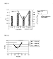
- FIG. 6 Further detailed data is shown in Fig. 6 as an embodiment of the present invention in the case of employing a recording speed of ⁇ 2.
- the horizontal axis represents ⁇ bw or Pbw
- the vertical axis on the left represents the scales of bar graphs, and also represents the absolute value of the tilt of each straight line in Fig. 5
- the vertical axis on the right represents the scale of a polygonal line graph, and also represents approximate accuracy ⁇ of each straight line.
- ⁇ bw increases, the tilt of the corresponding straight line increases.
- a greater tilt can be obtained in the case of fixing Pbw to 3.0.
- the value of ⁇ in this case is set to a great value, whereby the influence due to operating simultaneously with write power Pw is reduced, which is equivalent to the case of setting Pbw to a fixed value in a pseudo manner.
- Fig. 7 illustrates the relation between DCJ and main power Pw.
- the horizontal axis represents the main power Pw
- the vertical axis represents DCJ.
- the curve of DCJ can be prevented from being changed even if ⁇ bw is changed, so it can be found that an advantage obtained by increasing ⁇ bw is great.
- the write strategy such as shown in Fig. 3
- the present inventor has found as a non-evident matter that the power level of the space formation power Ps is decreased from the ordinary power level as a method for improving the linearity, i.e., the linear approximate accuracy ⁇ .
- the linearity i.e., the linear approximate accuracy ⁇ .
- dTtop of top pulse width Ttop of a mark equal to or longer than 3T is delayed to narrow down the substantial width so as to be in conjunction with this control.
- Such control improves the heat balance of each mark when setting the write power Pw high.
- the horizontal axis represents the main power Pw
- the vertical axis represents DCJ.
- a recording speed is ⁇ 1
- Pbw ⁇ Ps is stipulated with the BD standard, but in a case wherein a recording speed is ⁇ 2 or faster, the relation between Pbw and Ps has not been stipulated.
- the case shown in Fig. 8 is ⁇ 2 speed recording, and it can be found that the relations of Pbw ⁇ Ps and ⁇ bw ⁇ ⁇ ps hold. That is to say, in a case wherein a recording speed is ⁇ 2 or faster, it can be found that with regard to the relation between Pbw and Ps, the conditions completely contrary to the time of ⁇ 1 speed are more preferred.
- ⁇ 1 speed is linear velocity of 4.92 m/s
- linear velocity becomes double that linear velocity, i.e., 9.84 m/s.
- FIGs. 5 through 9 illustrate data in the case of ⁇ 2 speed.
- Pw 5.9 mW wherein DCJ becomes the minimum
- the horizontal axis represents the main power Pw
- the vertical axis represents the ⁇ value.
- the horizontal axis represents ⁇ bw and Pbw
- the vertical axis on the left represents the scales of bar graphs, and also represents the absolute value of the tilt of a straight line in Fig. 10
- the vertical axis on the right represents the scale of a polygonal line graph, and also represents approximate accuracy ⁇ of each straight line in Fig. 10 .
- ⁇ 1 speed unlike the case of ⁇ 2 speed, when ⁇ bw becomes great excessively, the tilt becomes small, and also linear approximate accuracy ⁇ deteriorates. Accordingly, ⁇ bw needs to be suppressed to around 0.256.
- Pbw 1.3 mW
- Fig. 12 represents the relation between DCJ and main power Pw.
- ⁇ bw changes, the curve of DCJ does not change at all.
- the power levels of ⁇ bw and Pbw are increased, and the power levels of ⁇ ps and Ps are decreased, whereby the relation between the asymmetry value or ⁇ value and main power Pw can be represented with a linear straight line while suppressing influence as to DCJ.
- a drive system includes an optical disc recording/playback device 100, an input/output system (not shown) including a display unit such as a television receiver, and an operating unit such as a remote controller.
- the optical disc recording/playback device 100 includes memory 127 storing data in the middle of processing, data of processing results, reference data in processing, and so forth, a control circuit 125 configured of a central processing unit (hereafter, abbreviated as "CPU") including a memory circuit 126 in which a program for performing processing described below is recorded, an interface unit (hereafter, abbreviated as "I/F") 128 which is an interface with an input/output system, a property value detection unit 124 for detecting the maximum amplitude level or the minimum amplitude level or the like of a RF signal which is a playback signal, a data demodulation circuit 123 for performing processing for decoding whether to read which of 2T through 8T codes (e.g., in the case of the BD standard, 9T which is a synchronizing code is also distinguished.
- CPU central processing unit
- I/F interface unit
- 2T through 11T codes and 13T which is a synchronizing code are distinguished) from a RF signal which is a playback signal, a pickup unit 110, a data modulation circuit 129 for subjecting data to be recorded output from the control circuit 125 to predetermined modulation, and outputting this to a laser diode (hereafter, abbreviated as "LD") driver 121, an LD driver 121, and a rotation control unit of an optical disc 150, a servo control unit for the motor and the pickup unit 110 (not shown), and so forth.
- LD laser diode
- the pickup unit 110 includes an objective lens 114, beam splitter 116, detection lens 115, collimator lens 113, LD 111, and photo detector (hereafter, abbreviated as "PD") 112.
- an actuator operates in response to control of the unshown servo control unit, and focusing and tracking are performed.
- the control unit 125 is connected to the memory 127, property value detection unit 124, I/F 128, LD driver 121, data modulation circuit 129, unshown rotation control unit and servo control unit, and so forth. Also, the property value detection unit 124 is connected to the PD 112, control circuit 125, and so forth.
- the LD driver 121 is connected to the data modulation circuit 129, -control circuit 125, and LD 111.
- the control circuit 125 is also connected to the input/output system through the I/F 128.
- the control circuit 125 controls the data modulation circuit 129 to subject data to be recorded in the optical disc 150 to predetermined modulation processing, and the data modulation circuit 129 outputs the data after the modulation processing to the LD driver 121.
- the LD driver 121 drives the LD 111 using the received data to output a laser beam in accordance with the specified recording conditions (strategy and parameters).
- the laser beam is irradiated onto the optical disc 150 through the collimator lens 113, beam splitter 116, and objective lens 114, where a mark and space are formed on the optical disc 150.
- the LD driver 121 drives the LD 111 to output a laser beam.
- the laser beam is irradiated onto the optical disc 150 through the collimator lens 113, beam splitter 116, and objective lens 114.
- the reflected beam from the optical disc 150 is input to the PD 112 through the objective lens 114, beam splitter 116, and detection lens 115.
- the PD 112 converts the reflected beam from the optical disc 150 into an electric signal, and outputs this to the property value detection unit 124 and so forth.
- the data modulation circuit 123 and so forth subject the output playback signal to predetermined decoding processing, outputs the decoded data to the display unit of the input/output system through the control circuit 125 and I/F 128, and displays the playback data.
- the property value detection unit 124 is not employed for ordinary playback.
- the control circuit 125 plays a media ID recorded in the optical disc 150 using the PD 112 and data modulation circuit 123, obtains the reflectivity of the optical disc 150 by comparing the played media ID and the media ID of an optical disc including a recording layer employing organic dye registered in the memory 127 beforehand, or by the property value detection unit 124 and so forth, determines whether or not the relevant reflectivity is a predetermined value, thereby determining whether or not the optical disc 150 to be subjected to data recording this time is an optical disc including a recording layer employing organic dye (step S1). In a case wherein the optical disc 150 to be subjected to data recording this time is not an optical disc including a recording layer employing organic dye, not the processing according to the present embodiment but normal processing is executed (step S21), and the processing ends.
- the control circuit 125 determines whether or not a recording speed is ⁇ 2 or faster based on the instructions or the like from a user, which were input through the I/F 128 (step S3). In a case wherein data recording is performed at x2 speed or faster, the control circuit 125 reads out parameters and various types of strategy, for example, including ⁇ ps and ⁇ bw having the relation such as ⁇ ps ⁇ ⁇ bw from the memory 127 or optical disc 150 (step S5), initializes the relevant parameters and various types of strategy data (step S7).
- the LD driver 121 and so forth are initialized based on the initial value of the main power Pw.
- parameters for ⁇ 1 speed are not employed here, but the parameters for a recording speed of ⁇ 2 or faster are set as to the parameters for ⁇ 1 speed, which includes the relation described in the section of "Principle of Present Invention".
- step S9 known processing is executed to optimize the main power Pw (step S9).
- the property value detection unit 124 detects the property values for calculating an asymmetry value or ⁇ value, and outputs these to the control circuit 125.
- the control circuit 125 sets ⁇ ps and ⁇ bw satisfying the space formation power Ps and bias power Pbw corresponding to the optimized main power Pw, i.e., Ps ⁇ Pbw, and executes data recording (step S11).
- the control circuit 125 reads out parameters and various types of strategy, for example, including ⁇ ps and ⁇ bw having the relation such as ⁇ ps ⁇ ⁇ bw from the memory 127 or optical disc 150 (step S13), initializes the relevant parameters and various types of strategy data (step S15).
- the value of power such as the space formation power Ps, and bias power Pbw depending on the main power Pw
- the LD driver 121 and so forth are initialized based on the initial value of the main power Pw.
- ⁇ ps is a value as small as possible.
- parameters for ⁇ 2 speed are not employed here, but the parameters for a recording speed of ⁇ 1 are set as to the parameters for ⁇ 2 speed or faster, which includes the relation described in the section of "Principle of Present Invention".
- step S17 known processing is executed to optimize the main power Pw (step S17).
- the property value detection unit 124 detects the property values for calculating an asymmetry value or ⁇ value, and outputs these to the control circuit 125.
- the control circuit 125 sets Ps and Pbw satisfying the space formation power Ps and bias power Pbw corresponding to the optimized main power Pw, i.e., Ps > Pbw, and executes data recording (step S19).
- Ps is a value as small as possible.
- ⁇ ps and ⁇ bw for ⁇ 1 speed recording and ⁇ 2 or faster speed recording are stored in the memory 127 or optical disc 150 in some cases. In the case of holding these in the optical disc 150, these are held in Lead-in area such as shown in Fig. 15 .
- Lead-in area is principally divided into a system Lead-in area, a connection area, and data Lead-in area, and the system Lead-in area includes an initial zone, buffer zone, control data zone, and buffer zone.
- the connection area includes a connection zone.
- the data Lead-in area includes a guard track zone, disc test zone, drive test zone, guard track zone, RMD duplication zone, recording management zone, R-physical format information zone, and reference code zone.
- the control data zone of the system Lead-in area includes a recording condition data zone 170. For example, ⁇ ps , ⁇ bw , and so forth are held in the recording condition data zone 170.
- the embodiment of the present invention has been described so far, but the present invention is not restricted to this.
- the functional block diagram shown in Fig. 13 is shown for describing the embodiment, so there is a case wherein the functional block is not necessarily identical to an actual circuit or module configuration.
- processing orders may be interchanged, or may be executed in parallel as long as the processing results are the same.
- the technique described in the section of "Principle of Present Invention” but also another technique may be employed to increase the tilt of a straight line representing the relation between the asymmetry value or ⁇ value and the main power Pw, and also improve linearity thereof.
- this technique include a technique wherein the top pulse length Ttop is lengthened regarding only short marks (e.g., 2T, 3T, 4T, etc.), a technique wherein the last pulse length Tlp is lengthened regarding code of 3T alone or 4T or more, and a technique wherein Ttop is shortened, thereby preventing a short mark from being written, similar to reduction in Ps, to increase the tilt of ⁇ at the time of fluctuation of Pw.
Landscapes
- Physics & Mathematics (AREA)
- Optics & Photonics (AREA)
- Optical Recording Or Reproduction (AREA)
- Optical Head (AREA)
- Optical Record Carriers And Manufacture Thereof (AREA)
Abstract
An optical disc recording method includes: a determining step for determining whether an optical disc to be recorded is an optical disc including a recording layer employing organic dye; and a control step for controlling a laser such that space formation power Ps necessary for space formation is equal to or smaller than bias power Pbw, in a case wherein determination is made that the optical disc includes a recording layer employing organic dye. In a case wherein the relation of Ps < Pbw is satisfied, the relation between the asymmetry value, β value, and main power Pw includes linearity. Accordingly, control of the main power Pw can be performed with the asymmetry value and β value as evaluation indexes, and accordingly, disturbance or the like can be readily handled.
Description
- The present invention relates to an art for appropriately subjecting an optical disc, including a recoding layer employing organic dye, to data recording.
- For example, an optical disc for recording to which the Blu-ray standard (hereafter, abbreviated as "BD standard") has been applied includes a disc-shaped substrate having spiral-shaped guide grooves (also referred to as pregrooves) on one face, a reflecting layer formed on one face of the substrate, a recording layer formed on the reflecting layer, and an optically-transparent cover layer formed on the recording layer. With such an optical disc, a recording laser beam is irradiated onto the recording layer on the pregrooves, i.e., onto the grooves to form a mark, thereby recording data. The recording laser beam is irradiated with multi-pulse-type recording pulse (write pulse) schematically illustrated in
Fig. 3 , or with a single-pulse-type recording pulse in some cases. With regard to this recoding pulse, space formation power Ps, which is the recording power necessary for space formation, is employed at the time of space formation, and main power Pw is employed at the time of mark formation. Bias power Pbw is employed between the pulses of the top pulse and thereafter with a mark of 3T or more, cooling pulsed power Pc is employed after the final pulse of the mark. Here, with the recording pulse according to the related art, as shown with a thick dotted line shown inFig. 3 , with formation of a mark of 3T or more, in order to prevent disorder on the shape of the mark from occurring due to the accumulation amount of heat generated by the laser irradiation corresponding to each pulse, the bias power Pbw is set smaller than the space formation power Ps. Of such optical discs, with regard to an optical disc including a recording layer employing an inorganic material, upon recording being performed with established recording setting conditions, i.e., strategy, properties such as shown inFig. 1 are obtained, for example. Specifically, the horizontal axis represents the main power (recording power at the time of mark formation) Pw, and the vertical axis on the left side represents DC jitter (%) (hereafter, abbreviated as DCJ), i.e., the level of positional and width irregularities when recording data is converted into a recording signal, and the vertical axis on the right side represents an asymmetry value (hereafter, abbreviated as "Asym" in the drawings). Note that DCJ is the standard deviation of the phase difference between a binary RF signal binarized from a RF signal and a clock signal generated from the binarized RF signal thereof. Also, the asymmetry value is an evaluation index representing the symmetry between the shortest recording mark and shortest space and the longest recording mark and longest space of a RF signal. Note that a β value may be employed instead of the asymmetry value. With the GND level as reference wherein AC coupling, i.e., the DC components of the RF signal are removed, if we say that the difference between the amplitude and GND level of the longest recording mark M8T is a, and the difference between the amplitude and GND level the longest space S8T is b, the β value is a numeric value (hereafter, referred to as "β value") computed with β = (a - b) / (a + b). - As shown in
Fig. 1 , DCJ represents a curve such as a quadratic function wherein the main power Pw becomes the minimum at the time of around 5.4 mW, and the asymmetry value increases generally in a linear manner as the main power Pw increases. With regard to an optical disc employing an inorganic material, in a case wherein there is a problem when detecting the asymmetry value or β value, the main power Pw is adjusted in accordance with the curve such as shown inFig. 1 , whereby a desired asymmetry value or β value can be obtained. Accordingly, for example, with working optimum power control (hereafter, abbreviated as WOPC) during operation or the like, control of the main power PW is performed with the asymmetry value as an evaluation index, whereby irregularities relating to a disc itself such as the film thickness, reflecting film thickness, plate thickness, warping, and so forth of a recording material, or irregularities relating to change in temperature of a laser diode, a drive such as servo operation or the like can be handled. - On the other hand, with regard to an optical disc including a recording layer employing organic dye, upon recording being performed with established strategy or the like, properties such as shown in
Fig. 2 are obtained, for example. The horizontal axis and vertical axes are similar to those inFig. 1 . In the case of organic dye as well, DCJ represents a curve such as a generally quadratic function in the same way as with the case of an inorganic material though the values are different, but with regard to the asymmetry value, we cannot find linearity such as shown inFig. 1 in the case of an inorganic material. That is to say, with the asymmetry value and β value, this state is a state
wherein determination cannot be made as to whether or not the appropriate main power Pw is set. - Note that with Japanese Unexamined Patent Application Publication No.
2003-323717 - As described above, when employing an optical disc employing organic dye, employment of established write strategy has a problem in that various irregularities such as described above cannot be handled with the asymmetry value or β value as an evaluation index.
- Further, in a case wherein the detection precision of the asymmetry value or β value is low, there is a need to increase the tilt of a straight line representing the relation between the asymmetry value or β value and the main power Pw. Also, there is a need to maintain the linearity of the straight line representing the relation between the asymmetry value or β value and the main power Pw.
- Accordingly, it is an object of the present invention to enable an optical disc including a recoding layer employing organic dye to be subjected to recording with excellent recording quality. That is to say, technology for enabling the relation between the asymmetry value or β value and the main power Pw to be represented with an appropriate straight line is employed, thereby subjecting the relevant optical disc to data recording with excellent quality.
- Also, it is another object of the present invention to provide technology for maintaining the linearity of the straight line representing the relation between the asymmetry value or β value and the main power Pw at the time of subjecting an optical disc including a recording layer employing organic dye to recording.
- An optical disc recording method according to a first aspect of the present invention includes: a determining step for determining whether an optical disc to be recorded is an optical disc including a recording layer employing organic dye; and a control step for controlling a laser such that space formation power Ps necessary for space formation is equal to or smaller than bias power Pbw, in a case wherein determination is made that the optical disc includes a recording layer employing organic dye. According to the non-obvious findings of the present inventor, in a case wherein a relation such as Ps ≤ Pbw is satisfied, the relation between the asymmetry value or β value and the main power Pw enhances the linearity. Accordingly, the main power Pw can be controlled with the asymmetry value or β value as an evaluation index, and accordingly, various irregularities relating to an optical disc itself to be subjected to data recording, and recording can be readily handled. That is to say, an optical disc employing organic dye can be subjected to appropriate data recording.
- Note that the control step may be executed in a case wherein the recording speed is ×2 or faster. With the BD standard, with regard to a recording speed of ×1 is stipulated with a condition of Ps > Pbw, so in the case of the BD standard, the control step needs to be performed regarding a recording speed is ×2 or faster.
- An optical disc recording/playback device according to a second aspect of the present invention includes: a unit configured to determine whether or not an optical disc to be written is an optical disc including a recording layer employing organic dye; and a control unit configured to control a laser such that space formation power Ps necessary for space formation is equal to or smaller than bias power Pbw, in a case wherein determination is made that the optical disc includes a recording layer employing organic dye. The parameters for determining Ps and Pbw may be stored in memory of the optical disc recording/playback device in some case.
- An optical disc including a recording layer employing organic dye according to a third aspect of the present invention stores the parameters satisfying the following relation

where εps represents a parameter for setting space formation power Ps necessary for forming space in the relevant optical disc, and εbw represents a parameter for setting bias power Pbw. Thus, the parameters for the relevant optical disc are stored in an optical disc to be subjected to data recording, whereby appropriate recording can be performed even with any optical disc recording/playback device. - The parameter εps and the parameter εbw may be parameters employed at a recording speed of ×2 or faster.
- Further, the parameter εps and the parameter εbW may be parameters to be multiplied by a mark formation power PW necessary for forming a mark in the optical disc. There is a case wherein adjustment is restricted to Ps = Pw × εps, Pbw = Pw × εbw depending on an optical disc recording/playback device, and the present invention can also handle such a restricted case.
- An optical disc recording method according to a fourth aspect of the present invention includes: a determining step for determining whether an optical disc to be recorded is an optical disc including a recording layer employing organic dye; a first recording step for performing data recording employing space formation power Ps1 necessary for space formation at a recording speed of ×1 and bias power Pbw1 at a recording speed of ×1, in a case wherein determination is made that the optical disc is an optical disc including a recording layer employing organic dye, and also a recording speed is ×1; and a second recording step for performing data recording employing space formation power Ps2 necessary for space formation at the relevant recording speed and bias power Pbw2 at the relevant recording speed, in a case wherein determination is made that the optical disc is an optical disc including a recording layer employing organic dye, and also a recording speed is ×2 or faster; with Ps1, Pbw1, Ps2, and Pbw2 being set so as to satisfy the following
condition 
- According to the non-obvious findings of the present inventor, in the case of the above-mentioned condition being satisfied, the relation between the asymmetry value or β value and the main power Pw has the linearity. Accordingly, the main power Pw can be controlled with the asymmetry value or β value as an evaluation index, and accordingly, various irregularities relating to an optical disc itself to be subjected to data recording, and recording can be readily handled. That is to say, an optical disc including a recording layer employing organic dye can be subjected to appropriate data recording.
- An optical disc recording/playback device according to a fifth aspect of the present invention includes: a determining unit configured to determine whether or not an optical disc to be written is an optical disc including a recording layer employing organic dye; and a control unit configured to perform control so as to satisfy the following
relation 
where Ps1 is space formation power necessary for space formation at a recording speed of ×1, Pbw1 is bias power at a recording speed of ×1, Ps2 is space formation power necessary for space formation at a recording speed of ×2 or faster, and Pbw2 is bias power at a recording speed of ×2 or faster, in a case wherein determination is made that the optical disc is an optical disc including a recording layer employing organic dye. The parameters for setting the above-mentioned power may be stored in memory of the optical disc recording/playback device. - An optical disc including a recording layer employing organic dye according to a sixth aspect of the present invention stores the parameters satisfying the following relation

where εps1 is a parameter for setting space formation power Ps1 necessary for space formation at a recording speed of ×1, εbw1 is a parameter for setting bias power Pbw1 at a recording speed of ×1, εps2 is a parameter for setting space formation power Ps2 necessary for space formation at a recording speed of ×2 or faster, and εbw2 is a parameter for setting bias power Pbw2 at a recording speed of ×2 or faster. Thus, the parameters for the relevant optical disc are stored in the optical disc, whereby appropriate recording can be performed even with any optical disc recording/playback device. - An optical disc recording method according to a seventh aspect of the present invention includes: a determining step for determining whether an optical disc to be recorded is an optical disc including a recording layer employing organic dye; a first recording step for performing data recording employing bias power Pbw1 at a recording speed of ×1, in a case wherein determination is made that the optical disc is an optical disc including a recording layer employing organic dye, and also a recording speed is ×1; and a second recording step for performing data recording employing bias power Pbw2 at the relevant recording speed, in a case wherein determination is made that the optical disc is an optical disc including a recording layer employing organic dye, and also a recording speed is ×2 or faster; with the Pbw1 and Pbw2 being set so as to satisfy the following
relation 
- According to the non-obvious findings of the present inventor, in the case of the above-mentioned condition being satisfied, the relation between the asymmetry value or β value and the main power Pw has the linearity. Accordingly, the main power Pw can be controlled with the asymmetry value or β value as an evaluation index, and accordingly, various irregularities relating to an optical disc itself to be subjected to data recording, and recording can be readily handled. That is to say, an optical disc including a recording layer employing organic dye can be subjected to appropriate data recording.
- An optical disc recording/playback device according to an eighth aspect of the present invention includes: a determining unit configured to determine whether or not an optical disc to be written is an optical disc including a recording layer employing organic dye; and a control unit configured to perform control so as to satisfy the following
relation 
wherein Pbw1 is bias power at a recording speed of ×1, and Pbw2 is bias power at a recording speed of ×2 or faster, in a case wherein determination is made that the optical disc includes a recording layer employing organic dye. The parameters for setting the above-mentioned power may be stored in memory of the optical disc recording/playback device. - An optical disc including a recording layer employing organic dye according to a ninth aspect of the present invention stores the parameters satisfying the following relation

where εbw1 is a parameter for setting bias power Pbw1 at a recording speed of ×1, and εbw2 is a parameter for setting bias power Pbw2 at a recording speed of ×2 or faster. Thus, the parameters for the relevant optical disc are stored in the optical disc, whereby appropriate recording can be performed even with any optical disc recording/playback device. - A program for causing a processor to execute the optical disc recording method of the present invention can be created, and the relevant program is stored in, for example, a recording medium such as a flexible disk, optical disc such as CD-ROM, magneto-optical disk, semiconductor memory, hard disk, or the like, storage device, or nonvolatile memory of a processor. Also, the program may be distributed with a digital signal over a network. Note that data being processed is temporarily stored in a storage device such as memory of a processor or the like.
- According to a feature of the present invention, when subjecting an optical disc including a recording layer employing organic dye to recording, the tilt and linearity of the relation between the asymmetry value or β value and the main power Pw is enhanced, and the relevant optical disc can be subjected to data recording with excellent quality at a high speed such as ×2 speed.
- Also, according to another feature of the present invention, when subjecting an optical disc including a recording layer employing organic dye to recording, the parameter information of the linearity of a straight line representing the relation between the asymmetry value or β value and the main power Pw can be held in the memory of the optical disc recording/playback device, an optical disc itself, or the like.
-
Fig. 1 is a diagram representing the relation between the main power Pw, DCJ, and asymmetry value of an optical disc including a recording layer employing an inorganic material. -
Fig. 2 is a diagram representing the relation between main power Pw, DCJ, and asymmetry value of an optical disc including a recording layer employing organic dye in a case wherein measurement was performed employing strategy data according to the related art. -
Fig. 3 is a diagram for describing the waveform of recording power according to the present embodiment. -
Fig. 4 is a diagram illustrating an improvement level of a curve representing the relation between the main power Pw and asymmetry value in a case wherein bias power Pbw is increased. -
Fig. 5 is a diagram for describing the relation between the main power Pw and β value in a case wherein the bias power Pbw according to the present invention is changed. -
Fig. 6 is a diagram for comparing a case wherein εbw is changed, and a case wherein the bias power Pbw is fixed regarding the linear tilt and linear approximation precision representing the relation between the main power Pw and β value according to the present invention. -
Fig. 7 is a diagram for describing the relation between the main power Pw and DCJ in a case wherein the bias power Pbw according to the present invention is changed. -
Fig. 8 is a diagram for describing the relation between the main power Pw and β value in a case wherein space formation power Ps according to the present invention is decreased. -
Fig. 9 is a diagram for describing the relation between the main power Pw and DCJ in a case wherein the space formation power Ps is decreased. -
Fig. 10 is a diagram representing the relation between the main power Pw and β value in a case wherein εbw is changed at a recording speed of ×1. -
Fig. 11 is a diagram representing the linear tilt and linear approximation precision representing the relation between the main power Pw and β value in a case wherein εbw is changed, and in a case wherein Pbw is fixed, at a recording speed of ×1. -
Fig. 12 is a diagram representing the relation between the main power Pw and DCJ in a case wherein εbw is changed at a recording speed of ×1. -
Fig. 13 is a functional block diagram according to and embodiment of the present invention. -
Fig. 14 is a diagram illustrating a processing flow according to an embodiment of the present invention. -
Fig. 15 is a diagram illustrating a data structure stored in an optical disc. - The present inventor has found a non-evident matter wherein in the case of an optical disc including a recording layer employing organic dye, the power level of the bias power Pbw is changed from control such as a pulse waveform shown with a dotted line in
Fig. 3 to the power level of bias power Pbwn such as a pulse waveform shown with a solid line, i.e., the power level of the bias power Pbw is increased up to equal to or greater than the power level of the space formation power Ps as compared to the that according to the related art, whereby the asymmetry value and main power Pw have linearity such as shown inFig. 4 . Note that the reason why the bias power Pbwn is displayed is to clarify how the bias power Pbw according to the related art increases to the increased bias power denoted with a symbol of Pbwn. However, the bias power will be described with a symbol of Pbw with the description other thanFig. 3 . - Particularly, it is generally desirable to increase the bias power Pbwn as compared to read power Pr at the time of playback. However, in a case wherein a condition such as recording device or the like differs, this relation does not hold in some cases, so caution is necessary.
- In
Fig. 4 , the horizontal axis represents the main power Pw, the vertical axis on the left side represents DCJ (%), and the vertical axis on the right side represents the asymmetry value Asym. There is no great difference between DCJ before improvement, i.e., DCJ in the case of the bias power Pbw according to the related art, and DCJ after improvement, i.e., DCJ in the case of the level of the bias power Pbw being increased, deterioration in recording quality is almost not seen, but in the case of after improvement, a relation is seen wherein when the main power Pw increases, the asymmetry value Asym decreases. - Note that in the case of an inorganic material, the polarity is high-to-low, so a straight line is drawn upward slanting to the right as the asymmetry value Asym, such as shown in
Fig. 1 , but in the case of an optical disc employing organic dye, the polarity is low-to-high, a straight line is drawn downward slanting to the right as the asymmetry value Asym, such as shown inFig. 4 . - The present invention is characterized in employing a write strategy wherein the space formation power Ps is equal to or smaller than the bias power Pbw to subject an optical disc to data recording. Also, the present invention is characterized in adjusting a recording system so as to readily reference the parameters for power control serving as such a write strategy. Note that the space formation power Ps is set somewhat smaller than a general power level according to the related art, which becomes a peripheral factor of the present invention.
- More detailed data is shown in
Fig. 5 as an embodiment of the present invention in the case of employing a recording speed of ×2.Fig. 5 illustrates the relation between the β value and main power Pw of each case of εbw = 0.254, εbw = 0.339, εbw = 0.424, and εbw = 0.508 when setting Pbw = Pw × εbw. As can be understood fromFig. 5 , in any case, the relation between the β value and main power Pw can be generally approximated to a linear function. - Further detailed data is shown in
Fig. 6 as an embodiment of the present invention in the case of employing a recording speed of ×2. InFig. 6 , the horizontal axis represents εbw or Pbw, the vertical axis on the left represents the scales of bar graphs, and also represents the absolute value of the tilt of each straight line inFig. 5 , the vertical axis on the right represents the scale of a polygonal line graph, and also represents approximate accuracy σ of each straight line. As can be understood fromFig. 6 , as εbw increases, the tilt of the corresponding straight line increases. - Further, a greater tilt can be obtained in the case of fixing Pbw to 3.0. The greater the tilt is, the more recording power can be readily controlled to obtain an appropriate value even if the detection precision of the β value is low, so it is desirable to set Pbw to not Pw × εbw but a fixed value wherein an independent power level of bias power Pbw is set without operating simultaneously with write power Pw.
- Note that a control method such as Pbw = Pw × εbw + α may be employed. The value of α in this case is set to a great value, whereby the influence due to operating simultaneously with write power Pw is reduced, which is equivalent to the case of setting Pbw to a fixed value in a pseudo manner.
- Particularly, in the case of setting Pbw to 3.0 fixedly, the linear approximate accuracy σ is a great value, which is more desirable. However, such setting cannot be performed depending on an optical disc recording/playback device currently offered commercially in some cases. Therefore, an experimental fact has been described regarding fixing Pbw.
- On the other hand, it can be found that when εbw increases, the linear approximate accuracy σ deteriorates. This can be considered as a phenomenon caused by a long mark being recorded too strongly when the bias power Pbw increases excessively. Accordingly, with this state as it is, εbw cannot be increased for the sake of the linear approximate accuracy σ, and the tilt of a line cannot be increased sufficiently.
- Note that
Fig. 7 illustrates the relation between DCJ and main power Pw. InFig. 7 , the horizontal axis represents the main power Pw, and the vertical axis represents DCJ. The curve of DCJ can be prevented from being changed even if εbw is changed, so it can be found that an advantage obtained by increasing εbw is great. However, for example, with the write strategy such as shown inFig. 3 , in a case wherein the power level of the bias power Pbw is increased to Pbwn, there is a need to adjust heat balance by narrowing down at least one of intermediate pulse width Tmp and final pulse width Tlp (3T). - Now, the present inventor has found as a non-evident matter that the power level of the space formation power Ps is decreased from the ordinary power level as a method for improving the linearity, i.e., the linear approximate accuracy σ. For example, only the top pulse start position dTtop of top pulse width Ttop of a mark equal to or longer than 3T is delayed to narrow down the substantial width so as to be in conjunction with this control. Such control improves the heat balance of each mark when setting the write power Pw high. Note that symbols relating to write strategy have been described on the premise of the symbols shown in
Fig. 3 . - This advantage is shown in
Fig. 8 . InFig. 8 , in a case wherein the pace formation power Ps is calculated with εps × Pw, the property relations between the main power Pw and β value in cases of εps = 0.25 and εps = 0.20 are represented with a primary approximation mathematical expression. Note that with εbw = 0.5, a recording speed is ×2. InFig. 8 , the horizontal axis represents the main power Pw, and the vertical axis represents β. As can be understood fromFig. 8 , the linear approximate accuracy (R2 here) improves, and the value of the tilt increases in the case of εps = 0.20 as compared to those in the case of εps = 0.25. - Also,
Fig. 9 illustrates the relation between the main power Pw and DCJ. Also, in this case as well, with εbw = 0.5, a recording speed is ×2. InFig. 9 , the horizontal axis represents the main power Pw, and the vertical axis represents DCJ. As can be understood fromFig. 9 , the curve of DCJ in the case of εps = 0.20 somewhat differs from that in the case of εps = 0.25, but there is no great deterioration. - As described above, it can be found that it is effective to decrease εps while increasing εbw. This is synonymous with decreasing Ps while increasing Pbw.
- Further, in a case wherein a recording speed is ×1, Pbw < Ps is stipulated with the BD standard, but in a case
wherein a recording speed is ×2 or faster, the relation between Pbw and Ps has not been stipulated. The case shown inFig. 8 is ×2 speed recording, and it can be found that the relations of Pbw ≥ Ps and εbw ≥ εps hold. That is to say, in a case wherein a recording speed is ×2 or faster, it can be found that with regard to the relation between Pbw and Ps, the conditions completely contrary to the time of ×1 speed are more preferred. Note that with the BD standard, ×1 speed is linear velocity of 4.92 m/s, and in the case of ×2 speed, linear velocity becomes double that linear velocity, i.e., 9.84 m/s. - Next, let us consider the relation between a recording speed of ×1 and that of ×2.
Figs. 5 through 9 illustrate data in the case of ×2 speed. Note that inFigs. 5 through 9 , in the case of Pw = 5.9 mW wherein DCJ becomes the minimum, Pbw = 1.5 mW in the case of εbw = 0.254, Pbw = 2.0 mW in the case of εbw = 0.339, Pbw = 2.5 mW in the case of εbw = 0.424, and Pbw = 3.0 mW in the case of εbw = 0.508. Also, inFigs. 5 through 7 , Ps = 1.5 mW in the case of εps = 0.254, and Pc = 0.1 mW in the case of εc = 0.017. - On the other hand, in order to compare with a case
wherein a recording speed is x2,Fig. 10 illustrates the relation between the β value and main power Pw in a case
wherein with a recording speed of ×1, in the case of εps = 0.333, and εc = 0.256, and when changing εbw to εbw = 0.333, εbw = 0.256, and εbw = 0.179. InFig. 10 , the horizontal axis represents the main power Pw, and the vertical axis represents the β value. Thus, in any case as well, a curve is drawn downward slanting to the right, which can be subjected to linear approximation. - This can be understood from
Fig. 11 as well. InFig. 11 , the horizontal axis represents εbw and Pbw, the vertical axis on the left represents the scales of bar graphs, and also represents the absolute value of the tilt of a straight line inFig. 10 , and the vertical axis on the right represents the scale of a polygonal line graph, and also represents approximate accuracy σ of each straight line inFig. 10 . In the case of ×1 speed, unlike the case of ×2 speed, when εbw becomes great excessively, the tilt becomes small, and also linear approximate accuracy σ deteriorates. Accordingly, εbw needs to be suppressed to around 0.256. However, like Pbw = 1.3 mW, it is desirable to fix Pbw in the same way as with the case of ×2 speed. - In the same way as with the case of β in the above-mentioned
Fig. 10 , in order to compare with a case
wherein a recording speed is ×2,Fig. 12 represents the relation between DCJ and main power Pw. As can be understood fromFig. 12 , even if εbw changes, the curve of DCJ does not change at all. Also, it can be found that DCJ becomes the minimum in the case of Pw = 3.9 mW. Note that at the time of Pw = 3.9 mW, Pbw = 0.7 mW in the case of εbw = 0.179, Pbw = 1.0 mW in the case of εbw = 0.256, and Pbw = 1.3 mW in the case of εbw = 0.333. Also, εbw = 0.333, so Ps = 1.3 mW, and εbw = 0.026, so Pc = 0.1 mW. - When DCJ is the minimum Pw, Ps1 / Pbw1 = 1.3 / 1.0 = 1.3 at εbw = 0.256 which is a range wherein linearity is acceptable in the case of ×1 speed, but Ps2 / Pbw2 = 1.5 / 2.5 = 0.6 at εbw = 0.424 which is a range wherein linearity is acceptable in the case of ×2 speed. That is to say, Ps1 / Pbw1 > Ps2 / Pbw2 holds. This is because a condition such as Ps ≤ Pbw is preferable in the case of ×2 speed or faster as described above though a condition such as Ps > Pbw is required in the case of ×1 speed. Similarly, εs1 / εbw1 > εs2 / εbw2 holds. Note that the number of the suffix of ε represents recording speed.
- Note that, additionally, a condition such as Ps > Pbw is required in the case of ×1 speed, but a condition such as Ps ≤ Pbw is preferable in the case of ×2 speed or faster, so Ps somewhat differs in the cases of ×1 speed and ×2 speed, but the relation of Pbw1 < Pbw2 holds, and εbw1 > εbw2 also holds.
- As described above, the power levels of εbw and Pbw are increased, and the power levels of εps and Ps are decreased, whereby the relation between the asymmetry value or β value and main power Pw can be represented with a linear straight line while suppressing influence as to DCJ.
- At this time, in the case of a recording speed of ×2 or faster, Ps ≤ Pbw holds, so εps ≤ εbw is preferable. Note that in the case of ×1 speed recording, Ps > Pbw is stipulated with the BD standard, but of this range an advantage can be obtained by decreasing the power level of Ps as much as possible.
- Further, when taking a recording speed into consideration, an advantage can be obtained in a case
wherein Ps1 / Pbw1 > Ps2 / Pbw2, εs1 / εbw1 > εs2 / εbw2, Pbw1 < Pbw2, and εbw1 < εbw2 hold. - A functional block diagram shown in
Fig. 13 of a drive system according to an embodiment of the present invention will be described. A drive system according to an embodiment of the present invention includes an optical disc recording/playback device 100, an input/output system (not shown) including a display unit such as a television receiver, and an operating unit such as a remote controller. - The optical disc recording/
playback device 100 includesmemory 127 storing data in the middle of processing, data of processing results, reference data in processing, and so forth, acontrol circuit 125 configured of a central processing unit (hereafter, abbreviated as "CPU") including amemory circuit 126 in which a program for performing processing described below is recorded, an interface unit (hereafter, abbreviated as "I/F") 128 which is an interface with an input/output system, a propertyvalue detection unit 124 for detecting the maximum amplitude level or the minimum amplitude level or the like of a RF signal which is a playback signal, adata demodulation circuit 123 for performing processing for decoding whether to read which of 2T through 8T codes (e.g., in the case of the BD standard, 9T which is a synchronizing code is also distinguished. Also, in the case of the HD-DVD standard, 2T through 11T codes and 13T which is a synchronizing code are distinguished) from a RF signal which is a playback signal, apickup unit 110, adata modulation circuit 129 for subjecting data to be recorded output from thecontrol circuit 125 to predetermined modulation, and outputting this to a laser diode (hereafter, abbreviated as "LD")driver 121, anLD driver 121, and a rotation control unit of anoptical disc 150, a servo control unit for the motor and the pickup unit 110 (not shown), and so forth. - Also, the
pickup unit 110 includes anobjective lens 114,beam splitter 116,detection lens 115,collimator lens 113,LD 111, and photo detector (hereafter, abbreviated as "PD") 112. With thepickup unit 110, an actuator operates in response to control of the unshown servo control unit, and focusing and tracking are performed. - The
control unit 125 is connected to thememory 127, propertyvalue detection unit 124, I/F 128,LD driver 121,data modulation circuit 129, unshown rotation control unit and servo control unit, and so forth. Also, the propertyvalue detection unit 124 is connected to thePD 112,control circuit 125, and so forth. TheLD driver 121 is connected to thedata modulation circuit 129, -control circuit 125, andLD 111. Thecontrol circuit 125 is also connected to the input/output system through the I/F 128. - Next, description will be made regarding processing overview in the case of subjecting the
optical disc 150 to data recording. First, thecontrol circuit 125 controls thedata modulation circuit 129 to subject data to be recorded in theoptical disc 150 to predetermined modulation processing, and thedata modulation circuit 129 outputs the data after the modulation processing to theLD driver 121. TheLD driver 121 drives theLD 111 using the received data to output a laser beam in accordance with the specified recording conditions (strategy and parameters). The laser beam is irradiated onto theoptical disc 150 through thecollimator lens 113,beam splitter 116, andobjective lens 114, where a mark and space are formed on theoptical disc 150. - Also, description will be made regarding processing overview in the case of playing the data recorded in the
optical disc 150. In response to the instructions from thecontrol circuit 125, theLD driver 121 drives theLD 111 to output a laser beam. The laser beam is irradiated onto theoptical disc 150 through thecollimator lens 113,beam splitter 116, andobjective lens 114. The reflected beam from theoptical disc 150 is input to thePD 112 through theobjective lens 114,beam splitter 116, anddetection lens 115. ThePD 112 converts the reflected beam from theoptical disc 150 into an electric signal, and outputs this to the propertyvalue detection unit 124 and so forth. Thedata modulation circuit 123 and so forth subject the output playback signal to predetermined decoding processing, outputs the decoded data to the display unit of the input/output system through thecontrol circuit 125 and I/F 128, and displays the playback data. The propertyvalue detection unit 124 is not employed for ordinary playback. - Next, description will be made regarding the operation of the optical disc recording/
playback device 100 with reference toFig. 14 . First, thecontrol circuit 125 plays a media ID recorded in theoptical disc 150 using thePD 112 anddata modulation circuit 123, obtains the reflectivity of theoptical disc 150 by comparing the played media ID and the media ID of an optical disc including a recording layer employing organic dye registered in thememory 127 beforehand, or by the propertyvalue detection unit 124 and so forth, determines whether or not the relevant reflectivity is a predetermined value, thereby determining whether or not theoptical disc 150 to be subjected to data recording this time is an optical disc including a recording layer employing organic dye (step S1). In a case wherein theoptical disc 150 to be subjected to data recording this time is not an optical disc including a recording layer employing organic dye, not the processing according to the present embodiment but normal processing is executed (step S21), and the processing ends. - On the other hand, in a case wherein determination is made that the
optical disc 150 to be subjected to data recording this time is an optical disc including a recording layer employing organic dye, thecontrol circuit 125 determines whether or not a recording speed is ×2 or faster based on the instructions or the like from a user, which were input through the I/F 128 (step S3). In a case wherein data recording is performed at x2 speed or faster, thecontrol circuit 125 reads out parameters and various types of strategy, for example, including εps and εbw having the relation such as εps ≤ εbw from thememory 127 or optical disc 150 (step S5), initializes the relevant parameters and various types of strategy data (step S7). With regard to the value of power such as the space formation power Ps, and bias power Pbw depending on the main power Pw, theLD driver 121 and so forth are initialized based on the initial value of the main power Pw. Note that parameters for ×1 speed are not employed here, but the parameters for a recording speed of ×2 or faster are set as to the parameters for ×1 speed, which includes the relation described in the section of "Principle of Present Invention". - Subsequently, known processing is executed to optimize the main power Pw (step S9). Note that, at this time, the property
value detection unit 124 detects the property values for calculating an asymmetry value or β value, and outputs these to thecontrol circuit 125. Subsequently, upon the main power Pw being optimized, thecontrol circuit 125 sets εps and εbw satisfying the space formation power Ps and bias power Pbw corresponding to the optimized main power Pw, i.e., Ps ≤ Pbw, and executes data recording (step S11). - Such processing yields advantages such as described in the section of "Principle of Present Invention", and further, with the WOPC or the like, control of the main power Pw can be performed appropriately.
- On the other hand, in the case of executing data recording at ×1 speed, the
control circuit 125 reads out parameters and various types of strategy, for example, including εps and εbw having the relation such as εps ≤ εbw from thememory 127 or optical disc 150 (step S13), initializes the relevant parameters and various types of strategy data (step S15). With regard to the value of power such as the space formation power Ps, and bias power Pbw depending on the main power Pw, theLD driver 121 and so forth are initialized based on the initial value of the main power Pw. Here, let us say that εps is a value as small as possible. Note that parameters for ×2 speed are not employed here, but the parameters for a recording speed of ×1 are set as to the parameters for ×2 speed or faster, which includes the relation described in the section of "Principle of Present Invention". - Subsequently, known processing is executed to optimize the main power Pw (step S17). Note that, at this time, the property
value detection unit 124 detects the property values for calculating an asymmetry value or β value, and outputs these to thecontrol circuit 125. Subsequently, upon the main power Pw being optimized, thecontrol circuit 125 sets Ps and Pbw satisfying the space formation power Ps and bias power Pbw corresponding to the optimized main power Pw, i.e., Ps > Pbw, and executes data recording (step S19). However, let us say that Ps is a value as small as possible. - Such processing yields advantages such as described in the section of "Principle of Present Invention", and further, with the WOPC or the like, control of the main power Pw can be performed appropriately.
- Note that εps and εbw for ×1 speed recording and ×2 or faster speed recording are stored in the
memory 127 oroptical disc 150 in some cases. In the case of holding these in theoptical disc 150, these are held in Lead-in area such as shown inFig. 15 . Lead-in area is principally divided into a system Lead-in area, a connection area, and data Lead-in area, and the system Lead-in area includes an initial zone, buffer zone, control data zone, and buffer zone. Also, the connection area includes a connection zone. Further, the data Lead-in area includes a guard track zone, disc test zone, drive test zone, guard track zone, RMD duplication zone, recording management zone, R-physical format information zone, and reference code zone. With the present embodiment, an arrangement is made wherein the control data zone of the system Lead-in area includes a recordingcondition data zone 170. For example, εps, εbw, and so forth are held in the recordingcondition data zone 170. - The embodiment of the present invention has been described so far, but the present invention is not restricted to this. For example, the functional block diagram shown in
Fig. 13 is shown for describing the embodiment, so there is a case wherein the functional block is not necessarily identical to an actual circuit or module configuration. Also, with regard to the processing flow as well, processing orders may be interchanged, or may be executed in parallel as long as the processing results are the same. - Note that not only the technique described in the section of "Principle of Present Invention" but also another technique may be employed to increase the tilt of a straight line representing the relation between the asymmetry value or β value and the main power Pw, and also improve linearity thereof. Examples of this technique include a technique
wherein the top pulse length Ttop is lengthened regarding only short marks (e.g., 2T, 3T, 4T, etc.), a technique
wherein the last pulse length Tlp is lengthened regarding code of 3T alone or 4T or more, and a technique wherein Ttop is shortened, thereby preventing a short mark from being written, similar to reduction in Ps, to increase the tilt of β at the time of fluctuation of Pw. This is because a contribution level of a short mark having little influence as to 18H fluctuation is enhanced, the fluctuation of the average level of a RF signal is increased as compared to 18H fluctuation as to the main power Pw, thereby increasing the β value in a case wherein the main power Pw is small, and decreasing the β value in a case wherein the main power Pw is great, and accordingly, the tilt of the straight line representing the relation between the asymmetry value or β value and the main power Pw should be increased.
Claims (13)
- An optical disc recording method comprising:a determining step for determining whether an optical disc to be recorded is an optical disc including a recording layer employing organic dye; anda controls step for controlling a laser such that space formation power Ps necessary for space formation is equal to or smaller than bias power Pbw, in a case wherein determination is made that said optical disc includes a recording layer employing organic dye.
- The optical disc recording method according to Claim 1, wherein said control step is executed in a case
wherein a recording speed is ×2 or faster. - An optical disc recording/playback device comprising:a determining unit configured to determine whether or not an optical disc to be written is an optical disc including a recording layer employing organic dye; anda control unit configured to control a laser such that space formation power Ps necessary for space formation is equal to or smaller than bias power Pbw, in a case wherein determination is made that said optical disc includes a recording layer employing organic dye.
- The optical disc recording/playback device according to Claim 3, wherein said control unit operates in a case wherein a recording speed is ×2 or faster.
- An optical disc including a recording layer employing organic dye said optical disc storing the parameters satisfying the following relation

where εps is a parameter for setting space formation power Ps necessary for forming space in the relevant optical disc, and εbw is a parameter for setting bias power Pbw. - The optical disc according to Claim 5, wherein said parameter εps and said parameter εbw are parameters employed at a recording speed of ×2 or faster.
- The optical disc according to Claim 5, wherein said parameter εps and said parameter εbw are parameters to be multiplied by a mark formation power PW necessary for forming a mark in said optical disc.
- An optical disc recording method comprising:a determining step for determining whether an optical disc to be recorded is an optical disc including a recording layer employing organic dye;a first recording step for performing data recording employing space formation power Ps1 necessary for space formation at a recording speed of ×1 and bias power Pbw1 at a recording speed of ×1, in a case wherein determination is made that said optical disc is an optical disc including a recording layer employing organic dye, and also a recording speed is ×1; anda second recording step for performing data recording employing space formation power Ps2 necessary for space formation at the relevant recording speed and bias power Pbw2 at the relevant recording speed, in a case wherein determination is made that said optical disc is an optical disc including a recording layer employing organic dye, and also a recording speed is ×2 or faster;wherein said Ps1, Pbw1, Ps2, and Pbw2 are set so as to satisfy the following condition

- An optical disc recording/playback device comprising:a determining unit configured to determine whether or not an optical disc to be written is an optical disc including a recording layer employing organic dye; anda control unit configured to perform control so as to satisfy the following relationwhere Ps1 is space formation power necessary for space formation at a recording speed of ×1, Pbw1 is bias power at a recording speed of ×1, Ps2 is space formation power necessary for space formation at a recording speed of ×2 or faster, and Pbw2 is bias power at a recording speed of ×2 or faster, in a case wherein determination is made that said optical disc is an optical disc including a recording layer employing organic dye.

- An optical disc including a recording layer employing organic dye storing the parameters satisfying the following relation

where εps1 is a parameter for setting space formation power Ps1 necessary for space formation at a recording speed of ×1, εbw1 is a parameter for setting bias power Pbw1 at a recording speed of ×1, εps2 is a parameter for setting space formation power Ps2 necessary for space formation at a recording speed of ×2 or faster, and εbw2 is a parameter for setting bias power Pbw2 at a recording speed of ×2 or faster. - An optical disc recording method comprising:a determining step for determining whether an optical disc to be recorded is an optical disc including a recording layer employing organic dye;a first recording step for performing data recording employing bias power Pbw1 at a recording speed of ×1, in a case wherein determination is made that said optical disc is an optical disc including a recording layer employing organic dye, and also a recording speed is ×1; anda second recording step for performing data recording employing bias power Pbw2 at the relevant recording speed, in a case wherein determination is made that said optical disc is an optical disc including a recording layer employing organic dye, and also a recording speed is ×2 or faster;wherein said Pbw1 and Pbw2 are set so as to satisfy the following relation

- An optical disc recording/playback device comprising:a determining unit configured to determine whether or not an optical disc to be written is an optical disc including a recording layer employing organic dye; anda control unit configured to perform control so as to satisfy the following relationwhere Pbw1 is bias power at a recording speed of ×1, and Pbw2 is bias power at a recording speed of ×2 or faster, in a case wherein determination is made that said optical disc includes a recording layer employing organic dye.

- An optical disc including a recording layer employing organic dye storing the parameters satisfying the following relation

where εbw1 is a parameter for setting bias power Pbw1 at a recording speed of ×1, and εbw2 is a parameter for setting bias power Pbw2 at a recording speed of ×2 or faster.
Applications Claiming Priority (1)
| Application Number | Priority Date | Filing Date | Title |
|---|---|---|---|
| JP2007198514A JP4537430B2 (en) | 2007-07-31 | 2007-07-31 | Optical disc recording method, optical disc recording / reproducing apparatus, and optical disc |
Publications (1)
| Publication Number | Publication Date |
|---|---|
| EP2026340A1 true EP2026340A1 (en) | 2009-02-18 |
Family
ID=39831008
Family Applications (1)
| Application Number | Title | Priority Date | Filing Date |
|---|---|---|---|
| EP08252585A Pending EP2026340A1 (en) | 2007-07-31 | 2008-07-30 | Optical disc recording method, optical disc recording/playback device, and optical disc |
Country Status (6)
| Country | Link |
|---|---|
| US (1) | US8223605B2 (en) |
| EP (1) | EP2026340A1 (en) |
| JP (1) | JP4537430B2 (en) |
| KR (1) | KR100966847B1 (en) |
| CN (1) | CN101359482B (en) |
| TW (1) | TWI396196B (en) |
Families Citing this family (1)
| Publication number | Priority date | Publication date | Assignee | Title |
|---|---|---|---|---|
| JP4537430B2 (en) * | 2007-07-31 | 2010-09-01 | 太陽誘電株式会社 | Optical disc recording method, optical disc recording / reproducing apparatus, and optical disc |
Citations (3)
| Publication number | Priority date | Publication date | Assignee | Title |
|---|---|---|---|---|
| EP1359572A2 (en) * | 2002-05-02 | 2003-11-05 | Pioneer Corporation | Information recording and reproducing apparatus and information recording method |
| US20040013065A1 (en) * | 2001-05-28 | 2004-01-22 | Toshiki Udagawa | Optical recorder and laser power control method |
| US20070070875A1 (en) * | 2005-09-14 | 2007-03-29 | Satoshi Mizukami | Recording method for dye-based recordable optical recording medium, recording medium, and recording apparatus using the same |
Family Cites Families (21)
| Publication number | Priority date | Publication date | Assignee | Title |
|---|---|---|---|---|
| JPS5894143A (en) * | 1981-12-01 | 1983-06-04 | Matsushita Electric Ind Co Ltd | optical recording and reproducing device |
| JPH0935269A (en) * | 1995-07-19 | 1997-02-07 | Mitsubishi Chem Corp | Recording method for optical information recording medium |
| JP3259643B2 (en) * | 1996-08-15 | 2002-02-25 | ヤマハ株式会社 | Optical disk recording device |
| EP2178086A3 (en) * | 1998-09-09 | 2010-07-21 | Mitsubishi Kagaku Media Co., Ltd. | Optical recording method |
| JP3230676B2 (en) * | 1999-10-28 | 2001-11-19 | 三菱化学株式会社 | Optical recording method and recording device |
| JP2001273636A (en) * | 2000-01-21 | 2001-10-05 | Mitsubishi Chemicals Corp | Optical recording method |
| JP2002150563A (en) * | 2000-09-01 | 2002-05-24 | Mitsubishi Chemicals Corp | Optical recording method and optical recording medium |
| JPWO2002089123A1 (en) | 2001-04-27 | 2004-08-19 | 松下電器産業株式会社 | Recordable optical disk, optical disk recording device, optical disk reproducing device, and method of recording data on recordable optical disk |
| JP3843000B2 (en) * | 2001-11-16 | 2006-11-08 | 三洋電機株式会社 | Optical disk recording device |
| AU2003211968A1 (en) * | 2002-02-13 | 2003-09-04 | Mitsubishi Chemical Corporation | Rewritable optical recording medium and optical recording method |
| DE60333366D1 (en) * | 2002-06-14 | 2010-08-26 | Pioneer Corp | INFORMATION RECORDING DEVICE AND INFORMATION REGISTRATION PROCESS |
| KR100877833B1 (en) * | 2002-07-05 | 2009-01-12 | 주식회사 히타치엘지 데이터 스토리지 코리아 | Method for detecting a defective area in an optical disc apparatus |
| JP2005032384A (en) * | 2003-07-10 | 2005-02-03 | Tdk Corp | OPTICAL RECORDING MEDIUM AND ITS MANUFACTURING METHOD, OPTICAL RECORDING MEDIUM MASTER AND ITS MANUFACTURING METHOD |
| CN1902057A (en) * | 2003-12-26 | 2007-01-24 | 三菱化学株式会社 | Optical recording medium and dye |
| JP2006120199A (en) | 2004-10-19 | 2006-05-11 | Hitachi Maxell Ltd | Information reproducing method and identifying method for optical recording medium |
| JP2006236420A (en) * | 2005-02-22 | 2006-09-07 | Toshiba Corp | Storage medium, reproducing method and recording method |
| WO2007029430A1 (en) * | 2005-09-05 | 2007-03-15 | Nec Corporation | Optical information reproducing method, optical information reproducing device, and optical information recording medium |
| TW200834558A (en) * | 2006-12-15 | 2008-08-16 | Taiyo Yuden Kk | Optical information recording device, optical information recording method, and optical information recording medium |
| CN101606198A (en) * | 2007-02-06 | 2009-12-16 | 日本电气株式会社 | Applied light power adjusting method and optical information recording/reproducing device |
| JP4537430B2 (en) * | 2007-07-31 | 2010-09-01 | 太陽誘電株式会社 | Optical disc recording method, optical disc recording / reproducing apparatus, and optical disc |
| JP5188200B2 (en) * | 2008-02-25 | 2013-04-24 | キヤノン株式会社 | Optical recording / reproducing device |
-
2007
- 2007-07-31 JP JP2007198514A patent/JP4537430B2/en not_active Expired - Fee Related
-
2008
- 2008-07-07 TW TW097125560A patent/TWI396196B/en not_active IP Right Cessation
- 2008-07-18 KR KR1020080069925A patent/KR100966847B1/en not_active Expired - Fee Related
- 2008-07-28 CN CN2008101346336A patent/CN101359482B/en not_active Expired - Fee Related
- 2008-07-30 EP EP08252585A patent/EP2026340A1/en active Pending
- 2008-07-30 US US12/182,794 patent/US8223605B2/en active Active
Patent Citations (4)
| Publication number | Priority date | Publication date | Assignee | Title |
|---|---|---|---|---|
| US20040013065A1 (en) * | 2001-05-28 | 2004-01-22 | Toshiki Udagawa | Optical recorder and laser power control method |
| EP1359572A2 (en) * | 2002-05-02 | 2003-11-05 | Pioneer Corporation | Information recording and reproducing apparatus and information recording method |
| JP2003323717A (en) | 2002-05-02 | 2003-11-14 | Pioneer Electronic Corp | Information recording and reproducing device and method |
| US20070070875A1 (en) * | 2005-09-14 | 2007-03-29 | Satoshi Mizukami | Recording method for dye-based recordable optical recording medium, recording medium, and recording apparatus using the same |
Also Published As
| Publication number | Publication date |
|---|---|
| JP2009037657A (en) | 2009-02-19 |
| KR100966847B1 (en) | 2010-06-29 |
| US20090067306A1 (en) | 2009-03-12 |
| TWI396196B (en) | 2013-05-11 |
| TW200923929A (en) | 2009-06-01 |
| CN101359482A (en) | 2009-02-04 |
| CN101359482B (en) | 2013-03-20 |
| KR20090013039A (en) | 2009-02-04 |
| JP4537430B2 (en) | 2010-09-01 |
| US8223605B2 (en) | 2012-07-17 |
Similar Documents
| Publication | Publication Date | Title |
|---|---|---|
| JP3807269B2 (en) | Optical disk device | |
| US8223605B2 (en) | Optical disc recording method, optical disc recording/playback device, and optical disc | |
| JP4545205B2 (en) | Optical disc recording / reproducing signal processing method, optical disc recording / reproducing apparatus, and program | |
| US8130617B2 (en) | Method of controlling playback condition, optical disk, optical disk drive device and program | |
| JP2006302332A (en) | Recording / playback device | |
| US8391114B2 (en) | Optical disk drive | |
| JP4363322B2 (en) | Optical information recording / reproducing apparatus | |
| JP5336155B2 (en) | Optical information recording apparatus and method | |
| US9293168B2 (en) | Quality evaluation method, information recording medium, optical disc device and recording/reproducing system | |
| JP4719724B2 (en) | Optical disc recording method, optical disc recording / reproducing apparatus, and optical disc | |
| JP4653779B2 (en) | Recording condition determining method, optical disc recording / reproducing apparatus, and optical disc | |
| JP2009245592A (en) | Optical disk recording method, optical disk recording and reproducing device, and optical disk | |
| US7567490B2 (en) | Optical disk recording method and an optical disk apparatus | |
| HK1150898B (en) | Optical information recording device and method | |
| JP2009295242A (en) | Data recording method, optical disk recording and reproducing device, and optical disk | |
| JP2012018713A (en) | Data recording method, optical disk recording and reproducing device and optical disk | |
| JP2009015883A (en) | Optical disc apparatus and control method thereof | |
| JP2008287765A (en) | Optical disc apparatus and optical disc recording / reproducing method |
Legal Events
| Date | Code | Title | Description |
|---|---|---|---|
| PUAI | Public reference made under article 153(3) epc to a published international application that has entered the european phase |
Free format text: ORIGINAL CODE: 0009012 |
|
| AK | Designated contracting states |
Kind code of ref document: A1 Designated state(s): AT BE BG CH CY CZ DE DK EE ES FI FR GB GR HR HU IE IS IT LI LT LU LV MC MT NL NO PL PT RO SE SI SK TR |
|
| AX | Request for extension of the european patent |
Extension state: AL BA MK RS |
|
| 17P | Request for examination filed |
Effective date: 20090803 |
|
| AKX | Designation fees paid |
Designated state(s): AT BE BG CH CY CZ DE DK EE ES FI FR GB GR HR HU IE IS IT LI LT LU LV MC MT NL NO PL PT RO SE SI SK TR |
|
| 17Q | First examination report despatched |
Effective date: 20110301 |