EP2026137A2 - System for measuring marking material on a surface, such as in color xerography - Google Patents
System for measuring marking material on a surface, such as in color xerography Download PDFInfo
- Publication number
- EP2026137A2 EP2026137A2 EP20080158403 EP08158403A EP2026137A2 EP 2026137 A2 EP2026137 A2 EP 2026137A2 EP 20080158403 EP20080158403 EP 20080158403 EP 08158403 A EP08158403 A EP 08158403A EP 2026137 A2 EP2026137 A2 EP 2026137A2
- Authority
- EP
- European Patent Office
- Prior art keywords
- imaging surface
- color
- light
- reflected
- toner
- Prior art date
- Legal status (The legal status is an assumption and is not a legal conclusion. Google has not performed a legal analysis and makes no representation as to the accuracy of the status listed.)
- Ceased
Links
- 239000000463 material Substances 0.000 title claims description 8
- 238000003384 imaging method Methods 0.000 claims abstract description 48
- 230000000295 complement effect Effects 0.000 claims abstract description 13
- 238000007639 printing Methods 0.000 claims abstract description 13
- 238000000034 method Methods 0.000 claims description 26
- 108091008695 photoreceptors Proteins 0.000 abstract description 35
- 238000000926 separation method Methods 0.000 description 6
- 238000012937 correction Methods 0.000 description 4
- 108020003175 receptors Proteins 0.000 description 4
- 238000012360 testing method Methods 0.000 description 4
- 238000003491 array Methods 0.000 description 3
- 239000002245 particle Substances 0.000 description 3
- 238000013459 approach Methods 0.000 description 2
- 239000003086 colorant Substances 0.000 description 2
- 230000007547 defect Effects 0.000 description 2
- 238000001514 detection method Methods 0.000 description 2
- 230000000694 effects Effects 0.000 description 2
- 238000005516 engineering process Methods 0.000 description 2
- 238000002955 isolation Methods 0.000 description 2
- 238000005259 measurement Methods 0.000 description 2
- 238000010606 normalization Methods 0.000 description 2
- 230000003287 optical effect Effects 0.000 description 2
- 238000011161 development Methods 0.000 description 1
- 238000010586 diagram Methods 0.000 description 1
- 230000005686 electrostatic field Effects 0.000 description 1
- 238000005286 illumination Methods 0.000 description 1
- 238000007641 inkjet printing Methods 0.000 description 1
- 239000007788 liquid Substances 0.000 description 1
- 230000007774 longterm Effects 0.000 description 1
- 238000012986 modification Methods 0.000 description 1
- 230000004048 modification Effects 0.000 description 1
- 238000007645 offset printing Methods 0.000 description 1
- 230000000737 periodic effect Effects 0.000 description 1
- 238000003908 quality control method Methods 0.000 description 1
- 238000002310 reflectometry Methods 0.000 description 1
- 230000035945 sensitivity Effects 0.000 description 1
- 238000012546 transfer Methods 0.000 description 1
Images

Classifications
-
- G—PHYSICS
- G03—PHOTOGRAPHY; CINEMATOGRAPHY; ANALOGOUS TECHNIQUES USING WAVES OTHER THAN OPTICAL WAVES; ELECTROGRAPHY; HOLOGRAPHY
- G03G—ELECTROGRAPHY; ELECTROPHOTOGRAPHY; MAGNETOGRAPHY
- G03G15/00—Apparatus for electrographic processes using a charge pattern
- G03G15/50—Machine control of apparatus for electrographic processes using a charge pattern, e.g. regulating differents parts of the machine, multimode copiers, microprocessor control
- G03G15/5033—Machine control of apparatus for electrographic processes using a charge pattern, e.g. regulating differents parts of the machine, multimode copiers, microprocessor control by measuring the photoconductor characteristics, e.g. temperature, or the characteristics of an image on the photoconductor
- G03G15/5041—Detecting a toner image, e.g. density, toner coverage, using a test patch
-
- G—PHYSICS
- G03—PHOTOGRAPHY; CINEMATOGRAPHY; ANALOGOUS TECHNIQUES USING WAVES OTHER THAN OPTICAL WAVES; ELECTROGRAPHY; HOLOGRAPHY
- G03G—ELECTROGRAPHY; ELECTROPHOTOGRAPHY; MAGNETOGRAPHY
- G03G15/00—Apparatus for electrographic processes using a charge pattern
- G03G15/02—Apparatus for electrographic processes using a charge pattern for laying down a uniform charge, e.g. for sensitising; Corona discharge devices
-
- G—PHYSICS
- G03—PHOTOGRAPHY; CINEMATOGRAPHY; ANALOGOUS TECHNIQUES USING WAVES OTHER THAN OPTICAL WAVES; ELECTROGRAPHY; HOLOGRAPHY
- G03G—ELECTROGRAPHY; ELECTROPHOTOGRAPHY; MAGNETOGRAPHY
- G03G15/00—Apparatus for electrographic processes using a charge pattern
-
- G—PHYSICS
- G03—PHOTOGRAPHY; CINEMATOGRAPHY; ANALOGOUS TECHNIQUES USING WAVES OTHER THAN OPTICAL WAVES; ELECTROGRAPHY; HOLOGRAPHY
- G03G—ELECTROGRAPHY; ELECTROPHOTOGRAPHY; MAGNETOGRAPHY
- G03G2215/00—Apparatus for electrophotographic processes
- G03G2215/00025—Machine control, e.g. regulating different parts of the machine
- G03G2215/00029—Image density detection
- G03G2215/00033—Image density detection on recording member
- G03G2215/00037—Toner image detection
- G03G2215/00042—Optical detection
-
- G—PHYSICS
- G03—PHOTOGRAPHY; CINEMATOGRAPHY; ANALOGOUS TECHNIQUES USING WAVES OTHER THAN OPTICAL WAVES; ELECTROGRAPHY; HOLOGRAPHY
- G03G—ELECTROGRAPHY; ELECTROPHOTOGRAPHY; MAGNETOGRAPHY
- G03G2215/00—Apparatus for electrophotographic processes
- G03G2215/01—Apparatus for electrophotographic processes for producing multicoloured copies
- G03G2215/0151—Apparatus for electrophotographic processes for producing multicoloured copies characterised by the technical problem
- G03G2215/0164—Uniformity control of the toner density at separate colour transfers
Definitions
- the present disclosure relates to systems for measuring marking material on a surface, as would be found, for instance, in measuring the density of toner particles on an electrostatographic or xerographic imaging member.
- Electrostatographic or xerographic copiers, printers and digital imaging systems typically record an electrostatic latent image on an imaging member.
- the latent image corresponds to the informational areas contained within a document being reproduced.
- a uniform charge is placed on a photoconductive member and portions of the photoconductive member are discharged by a scanning laser or other light source to create the latent image.
- the latent image is then developed by bringing a developer, including colorants, such as, for example, toner particles, into contact with the latent image.
- the toner particles carry a charge and are attracted away from a toner supply and toward the latent image by an electrostatic field related to the latent image, thereby forming a toner image on the imaging member.
- the toner image is subsequently transferred to a physical media, such as a print sheet.
- the print sheet, having the toner image thereon, is then advanced to a fusing station for permanently affixing the toner image to the print sheet.
- multi-color electrophotographic printing multiple latent images corresponding to each color separation are recorded on one or more photoconductive surfaces.
- the electrostatic latent image for each color separation is developed with toner of that color.
- each color separation is ultimately transferred to the print sheet in superimposed registration with the other toner images, creating, for example, a multi-layered toner image on the print sheet.
- This multi-layer toner image is permanently affixed to the print sheet to form a finished print.
- a method of operating a printing apparatus comprising a member defining a substantially shiny imaging surface, and a photosensor array disposed to receive light reflected from the imaging surface.
- a quantity of marking material of a first color is placed on the imaging surface.
- Data based on light reflected from the imaging surface is recorded.
- the reflected light is substantially entirely specularly reflected and filtered to a first filter color effectively complementary to the first color.
- a method of operating a printing apparatus comprising a member defining a substantially shiny imaging surface, and at least one photosensor array disposed to receive light reflected from the imaging surface.
- a plurality of patches of a first color is placed on the imaging surface, each patch having a predetermined target density, each patch extending across the image receptor.
- a plurality of patches of a second color is placed on the imaging surface, each patch having a predetermined target density, each patch extending across the image receptor.
- a first set of data based on light reflected from the imaging surface is recorded, the light being substantially entirely specularly reflected and filtered to a first filter color effectively complementary to the first color.
- a second set of data is recorded based on light reflected from the imaging surface, the light being substantially entirely specularly reflected and filtered to a second filter color effectively complementary to the second color. At least one of the first set of data and the second set of data is used to derive a gain function for at least one plurality of individual photosensors in at least one photosensor array.
- FIG. 1 is a simplified elevational view of essential elements of one type of a color printer, showing a context in which embodiments of the present disclosure may be utilized. Specifically, there is shown an "image-on-image" xerographic color printer, in which successive primary-color images are accumulated on a photoreceptor belt, and the accumulated superimposed images are in one step directly transferred to an output sheet as a full-color image.
- an "image-on-image" xerographic color printer in which successive primary-color images are accumulated on a photoreceptor belt, and the accumulated superimposed images are in one step directly transferred to an output sheet as a full-color image.
- the color printer of FIG. 1 includes an image receptor in the form of a belt photoreceptor 10, along which are disposed a series of stations, as is generally familiar in the art of xerography, one set for each primary color to be printed. For instance, to place a cyan color separation image on photoreceptor 10, there is used a charge corotron 12C, an imaging laser 14C, and a development unit 16C. For successive color separations, there is provided equivalent elements 12C, 14C, 16C (for cyan), 12M, 14M, 16M (for magenta), 12Y, 14Y, 16Y (for yellow), and 12K, 14K, 16K (for black).
- the photoreceptor 10 can be considered an "imaging surface,” and the toners of any kind can be considered a "marking material,” although these terms can be applied to any marking technology, such as ionography, liquid xerography, ink-jet, offset printing, etc.; and the imaging surface can be any kind of intermediate member or print sheet, depending on a given marking technology.
- FIG. 1 Also shown in FIG. 1 is what can be generally called a "monitor" 50, which can feed back to a control device 54.
- the monitor 50 can make measurements to images created on the photoreceptor 10.
- the information gathered therefrom is used by control device 54 in various ways to control in the operation of the printer, whether in a real-time feedback loop, an offline calibration process, a registration system, etc.
- FIG. 2 is a simplified elevational view of elements of a monitor 50 for recording images on an imaging surface of photoreceptor 10.
- Monitor 50 includes a light source 60 that transmits light to a predetermined area on the moving photoreceptor 10, and a photosensor array generally indicated as 62 that records light reflected from the photoreceptor 10.
- an imaging lens 64 such as a Selfoc® lens, in front of the photosensor array 62.
- the angle ⁇ of illumination of light source 60 relative to the surface of photoreceptor 10 is equal to the angle ⁇ of detection of photosensor array 62 relative to the surface of photoreceptor 10; in this way, photosensor array 62 receives substantially only specularly-reflected light reflected from the surface of photoreceptor 10.
- each array has a filter associated therewith, to accept a "filter color” of red, green, and blue light respectively.
- each photosensor in each array is comparable to the size of a pixel that could be placed on the photoreceptor (or other imaging member) by the printing apparatus, so that any detected image defect associated with one photosensor can be "matched” with a pixel created by the printing apparatus, thereby allowing correction of, for example, an individual, identified LED in an LED bar, or an ejector in an ink-jet printing system.
- photoreceptor 10 can be characterized as "shiny.”
- the term “shiny” shall mean that there is relatively little light diffusely reflected from the surface; when the light source and photosensor array are positioned as shown in FIG. 2 , it can reasonably be said that the detected light is almost entirely specularly reflected.
- any quantity of toner is placed on the photoreceptor surface, however, not only is the color of the surface effectively changed, but the characteristic of reflected light as well: whereas the bare photoreceptor is shiny, the optical roughness of the unfused toner layer makes the surface to varying extents diffuse. The diffuse quality of the toner layer will cause diffusely-reflected light from the toner layer to mix in with the specularly-reflected light from the shiny surface being detected by photosensor array 62.
- the admixture of unpredictable amounts of diffusely-reflected light into an overall "specular" system is a source of error that can affect the performance of an entire image quality control system.
- the diffusely-reflected light reflected from a given point on the photoreceptor 10 will be directed not only to the individual photosensor directly corresponding to the point, but possibly also to adjacent photosensors along the array at various distances from the point.
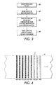
- FIG. 3 is a flowchart showing a calibration method used with the apparatus as described above, as would occur at periodic or as-needed calibration operations for the whole system.
- the illustrated steps are applied individually to each photosensor in an array, such as to determine the offset and gain associated with that particular photosensor; any signal corrections performed on subsequent signals from the photosensor are typically applied to that photosensor only.
- a "profile" (readings from each individual photosensor across an array) is obtained with light off, to determine the offset for each individual photosensor of a given color. For all captures in this embodiment, many scan lines are captured and the results averaged to get rid of thermal noise. In an embodiment having multiple linear arrays of photosensors, this light-off profile is obtained for each array separately.
- a profile is obtained of the bare photoreceptor belt with the light on. This profile is used with above dark capture to determine the gain of each photosensor, including any effect of across the belt reflectance variation (typically very little), lamp variation, and responsivity variation. All subsequent captures are then corrected for pixel by pixel offset and gain. As with the offset profile described above, in an embodiment having multiple linear arrays of photosensors, the gain-correction profile is obtained for each array separately.
- a series of cyan halftone patches are developed on the photoreceptor and then are recorded, using only the channel corresponding to the complementary-color array, in this case the red array 66R.
- the signal corresponding to each patch is proportional to the amount of photoreceptor surface that is not covered by toner, e.g., a 10% coverage patch will have about 90% of full signal.
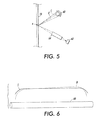
- FIG. 4 is a plan view showing a series of halftone patches, each indicated as T, and corresponding to each of a set of target halftone values, extending across the photoreceptor 10, as would apply to each single color in the tests described at step 404.
- T halftone patches
- target densities 10%, 20%, etc.
- this process of creating patterns and recording with an at least substantially complementary color is repeated for other colors; in one embodiment, magenta and yellow sets of patterns are created on the photoreceptor 10, each of which are measured through the blue photosensors. Also in such an embodiment, a black set of patterns is measured through the red photosensors. In alternative embodiments, blue-filtered photosensors measure yellow patterns, red-filtered photosensors measure cyan patterns, and any set of photosensors (including unfiltered "white" photosensors, if available) can be used to measure black patterns.
- a curve of signal versus toner coverage is determined for each photosensor in the array.
- the curve can be used to influence algorithms relating to the tone response curve (TRC), or the relationship between amount of toner placed versus darkness of the imaging surface or resultant print for a particular color, as manifest in the larger control system of the printer.
- TRC tone response curve
- a different curve is obtained for each of a plurality of photosensors, or all of the photosensors, in a given array, to facilitate the location, isolation, and correction of "bad" pixels that are causing streaks in the output prints.
- the photosensors 66R, 66B, 66G are used in specular mode to detect how much of the photoreceptor 10 is bare, while minimizing the influence of any diffusely-reflected light, particularly if the specular reflected light and diffuse reflected light do not have similar profiles along a given photosensor array.
- the use of the complementary color photosensors in measuring the primary-color patterns allows only one color light through to each photosensor, and since each photosensor is filtered to the complement of the light reflected from the toner, any diffusely-reflected light is almost entirely excluded from detection.
- the imaging lens 64 causes light, whether specular or diffuse, from one small area on the photoreceptor 10 to reach one photosensor, with no mixing from adjacent small areas.
- the error caused by diffuse light from a toner layer on photoreceptor 10 relates to the assumption that diffuse light is zero using a specular-only calibration method. In contrast, if only white light were used for calibration, it would be impossible to distinguish toner coverage variation from the diffuse/specular nonuniformity variation.
- FIG. 5 is a diagram illustrating the behavior of light in the system shown in FIG. 2 , explaining another source of calibration error which can be obviated by the above-described method.
- an imaging lens 64 such as a Selfoc® lens includes an arrangement of small lenslets.
- the original light from lamp 60 directed to the point X can be considered a cone C, having a thick end as the relatively large size of the lamp 60 narrowing to a point at X.
- the light reflected from X is transmitted through imaging lens 64 with minimal loss.
- the total amount of light captured by the photosensor will be small, relative to the total captured light specularly reflected off the bare photoreceptor belt, and thus the error induced by the normalization process will be a very small fraction of the total signal range.
- FIG. 6 shows typical profiles associated with a single lamp 60 (along a direction going into the page in the view of FIG. 2 ).
- the quality of light at different portions of, for example, a fluorescent lamp will result in different reflectivities of a specular versus a diffuse surface, as shown by the different shapes of the curves S and D associated with lamp 60.
- specular light is measured using complementary-filtered light, obviates this lamp-profile source of error.
Landscapes
- Physics & Mathematics (AREA)
- General Physics & Mathematics (AREA)
- Engineering & Computer Science (AREA)
- Microelectronics & Electronic Packaging (AREA)
- Plasma & Fusion (AREA)
- Control Or Security For Electrophotography (AREA)
- Color Electrophotography (AREA)
- Photoreceptors In Electrophotography (AREA)
- Developing Agents For Electrophotography (AREA)
- Investigating Or Analysing Materials By Optical Means (AREA)
Abstract
Description
- The present disclosure relates to systems for measuring marking material on a surface, as would be found, for instance, in measuring the density of toner particles on an electrostatographic or xerographic imaging member.
- Electrostatographic or xerographic copiers, printers and digital imaging systems typically record an electrostatic latent image on an imaging member. The latent image corresponds to the informational areas contained within a document being reproduced. In one type of such a system, a uniform charge is placed on a photoconductive member and portions of the photoconductive member are discharged by a scanning laser or other light source to create the latent image. The latent image is then developed by bringing a developer, including colorants, such as, for example, toner particles, into contact with the latent image. The toner particles carry a charge and are attracted away from a toner supply and toward the latent image by an electrostatic field related to the latent image, thereby forming a toner image on the imaging member. The toner image is subsequently transferred to a physical media, such as a print sheet. The print sheet, having the toner image thereon, is then advanced to a fusing station for permanently affixing the toner image to the print sheet.
- In multi-color electrophotographic printing, multiple latent images corresponding to each color separation are recorded on one or more photoconductive surfaces. The electrostatic latent image for each color separation is developed with toner of that color. Thereafter, each color separation is ultimately transferred to the print sheet in superimposed registration with the other toner images, creating, for example, a multi-layered toner image on the print sheet. This multi-layer toner image is permanently affixed to the print sheet to form a finished print.
- In any printing apparatus, it is desirable to set up a feedback system by which the quality of output prints is monitored, and the behavior of the apparatus is monitored to counteract any detected print defects.
U.S. Published Patent Application 2007/0003302 describes an extensive feedback system, wherein images (test images, or images such as those to be printed) are recorded in detail from the imaging surface of a photoreceptor, using input scanning hardware comparable in resolution and quality to that used for recording hard-copy images in a digital copier. A photosensor array is directed toward the photoreceptor to record the actual distribution of toner in response to the creation of test images. As mentioned in the Application, however, there are practical problems with reading toner-based test patterns, especially when trying to use specularly-reflected light in high toner density ranges, to increase the sensitivity of the measurements to spatial variation in toner density. - According to one aspect, there is provided a method of operating a printing apparatus, the printing apparatus comprising a member defining a substantially shiny imaging surface, and a photosensor array disposed to receive light reflected from the imaging surface. A quantity of marking material of a first color is placed on the imaging surface. Data based on light reflected from the imaging surface is recorded. The reflected light is substantially entirely specularly reflected and filtered to a first filter color effectively complementary to the first color.
- According to another aspect, there is provided a method of operating a printing apparatus, the printing apparatus comprising a member defining a substantially shiny imaging surface, and at least one photosensor array disposed to receive light reflected from the imaging surface. A plurality of patches of a first color is placed on the imaging surface, each patch having a predetermined target density, each patch extending across the image receptor. A plurality of patches of a second color is placed on the imaging surface, each patch having a predetermined target density, each patch extending across the image receptor. A first set of data based on light reflected from the imaging surface is recorded, the light being substantially entirely specularly reflected and filtered to a first filter color effectively complementary to the first color. A second set of data is recorded based on light reflected from the imaging surface, the light being substantially entirely specularly reflected and filtered to a second filter color effectively complementary to the second color. At least one of the first set of data and the second set of data is used to derive a gain function for at least one plurality of individual photosensors in at least one photosensor array.
-
-
FIG. 1 is a simplified elevational view of essential elements of one type of a color printer. -
FIG. 2 is a simplified elevational view of elements of a monitor for recording images on an imaging surface of photoreceptor. -
FIG. 3 is a flowchart showing a calibration method used with the apparatus ofFIGS. 1 and 2 . -
FIG. 4 is a plan view showing a series of halftone patterns extending across an image receptor. -
FIG. 5 is a simplified elevational view of elements of a monitor for recording images on an imaging surface of photoreceptor, showing a source of one type of calibration error. -
FIG. 6 shows a lamp in isolation, along with typical profiles associated with different portions of the length of the lamp. -
FIG. 1 is a simplified elevational view of essential elements of one type of a color printer, showing a context in which embodiments of the present disclosure may be utilized. Specifically, there is shown an "image-on-image" xerographic color printer, in which successive primary-color images are accumulated on a photoreceptor belt, and the accumulated superimposed images are in one step directly transferred to an output sheet as a full-color image. - The color printer of
FIG. 1 includes an image receptor in the form of abelt photoreceptor 10, along which are disposed a series of stations, as is generally familiar in the art of xerography, one set for each primary color to be printed. For instance, to place a cyan color separation image onphotoreceptor 10, there is used acharge corotron 12C, animaging laser 14C, and adevelopment unit 16C. For successive color separations, there is providedequivalent elements photoreceptor 10, and then the combined full-color image is transferred attransfer station 20 to an output sheet. The output sheet is then run through afuser 30, as is familiar in xerography. In this embodiment, thephotoreceptor 10 can be considered an "imaging surface," and the toners of any kind can be considered a "marking material," although these terms can be applied to any marking technology, such as ionography, liquid xerography, ink-jet, offset printing, etc.; and the imaging surface can be any kind of intermediate member or print sheet, depending on a given marking technology. - Also shown in
FIG. 1 is what can be generally called a "monitor" 50, which can feed back to acontrol device 54. Themonitor 50 can make measurements to images created on thephotoreceptor 10. The information gathered therefrom is used bycontrol device 54 in various ways to control in the operation of the printer, whether in a real-time feedback loop, an offline calibration process, a registration system, etc. -
FIG. 2 is a simplified elevational view of elements of amonitor 50 for recording images on an imaging surface ofphotoreceptor 10.Monitor 50 includes alight source 60 that transmits light to a predetermined area on the movingphotoreceptor 10, and a photosensor array generally indicated as 62 that records light reflected from thephotoreceptor 10. There may also be provided animaging lens 64, such as a Selfoc® lens, in front of thephotosensor array 62. As shown, the angle Φ of illumination oflight source 60 relative to the surface ofphotoreceptor 10 is equal to the angle Φ of detection ofphotosensor array 62 relative to the surface ofphotoreceptor 10; in this way,photosensor array 62 receives substantially only specularly-reflected light reflected from the surface ofphotoreceptor 10. - As can be seen, in this embodiment there are provided three parallel linear arrays of photosensors (extending into the page in the view of
FIG. 2 ), marked 66R, 66G, and 66B. Each array has a filter associated therewith, to accept a "filter color" of red, green, and blue light respectively. (In an alternative embodiment, still under the rubric of "filtered light" or a "filter color," there can be provided a single linear array of photosensors, and multiple, selectable light sources such as LEDs, each source emitting a particular color of light, such as red, green and blue.) The size of each photosensor in each array is comparable to the size of a pixel that could be placed on the photoreceptor (or other imaging member) by the printing apparatus, so that any detected image defect associated with one photosensor can be "matched" with a pixel created by the printing apparatus, thereby allowing correction of, for example, an individual, identified LED in an LED bar, or an ejector in an ink-jet printing system. - Many common designs of
photoreceptor 10 can be characterized as "shiny." As used herein, the term "shiny" shall mean that there is relatively little light diffusely reflected from the surface; when the light source and photosensor array are positioned as shown inFIG. 2 , it can reasonably be said that the detected light is almost entirely specularly reflected. When any quantity of toner is placed on the photoreceptor surface, however, not only is the color of the surface effectively changed, but the characteristic of reflected light as well: whereas the bare photoreceptor is shiny, the optical roughness of the unfused toner layer makes the surface to varying extents diffuse. The diffuse quality of the toner layer will cause diffusely-reflected light from the toner layer to mix in with the specularly-reflected light from the shiny surface being detected byphotosensor array 62. - The admixture of unpredictable amounts of diffusely-reflected light into an overall "specular" system is a source of error that can affect the performance of an entire image quality control system. The diffusely-reflected light reflected from a given point on the
photoreceptor 10 will be directed not only to the individual photosensor directly corresponding to the point, but possibly also to adjacent photosensors along the array at various distances from the point. -
FIG. 3 is a flowchart showing a calibration method used with the apparatus as described above, as would occur at periodic or as-needed calibration operations for the whole system. The illustrated steps, in one embodiment, are applied individually to each photosensor in an array, such as to determine the offset and gain associated with that particular photosensor; any signal corrections performed on subsequent signals from the photosensor are typically applied to that photosensor only. - At step 300 a "profile" (readings from each individual photosensor across an array) is obtained with light off, to determine the offset for each individual photosensor of a given color. For all captures in this embodiment, many scan lines are captured and the results averaged to get rid of thermal noise. In an embodiment having multiple linear arrays of photosensors, this light-off profile is obtained for each array separately.
- At step 302 a profile is obtained of the bare photoreceptor belt with the light on. This profile is used with above dark capture to determine the gain of each photosensor, including any effect of across the belt reflectance variation (typically very little), lamp variation, and responsivity variation. All subsequent captures are then corrected for pixel by pixel offset and gain. As with the offset profile described above, in an embodiment having multiple linear arrays of photosensors, the gain-correction profile is obtained for each array separately.
- At step 304 a series of cyan halftone patches are developed on the photoreceptor and then are recorded, using only the channel corresponding to the complementary-color array, in this case the
red array 66R. The signal corresponding to each patch is proportional to the amount of photoreceptor surface that is not covered by toner, e.g., a 10% coverage patch will have about 90% of full signal. There will be small amount of diffusely-reflected light that is directly proportional to the amount of coverage, but the use of complementary light tends to minimize this source of noise. -
FIG. 4 is a plan view showing a series of halftone patches, each indicated as T, and corresponding to each of a set of target halftone values, extending across thephotoreceptor 10, as would apply to each single color in the tests described at step 404. In the illustrated embodiment, for each color there is made eight patches T, of target densities of 10%, 20%, etc., each extending across thephotoreceptor 10, and thus corresponding to an entire length of each photosensor array such as 66G. - Returning to
FIG. 3 , this process of creating patterns and recording with an at least substantially complementary color, as atstep 304, is repeated for other colors; in one embodiment, magenta and yellow sets of patterns are created on thephotoreceptor 10, each of which are measured through the blue photosensors. Also in such an embodiment, a black set of patterns is measured through the red photosensors. In alternative embodiments, blue-filtered photosensors measure yellow patterns, red-filtered photosensors measure cyan patterns, and any set of photosensors (including unfiltered "white" photosensors, if available) can be used to measure black patterns. - At step 306 a curve of signal versus toner coverage is determined for each photosensor in the array. Broadly speaking, the curve can be used to influence algorithms relating to the tone response curve (TRC), or the relationship between amount of toner placed versus darkness of the imaging surface or resultant print for a particular color, as manifest in the larger control system of the printer. A different curve is obtained for each of a plurality of photosensors, or all of the photosensors, in a given array, to facilitate the location, isolation, and correction of "bad" pixels that are causing streaks in the output prints.
- In the present embodiment, the
photosensors photoreceptor 10 is bare, while minimizing the influence of any diffusely-reflected light, particularly if the specular reflected light and diffuse reflected light do not have similar profiles along a given photosensor array. The use of the complementary color photosensors in measuring the primary-color patterns allows only one color light through to each photosensor, and since each photosensor is filtered to the complement of the light reflected from the toner, any diffusely-reflected light is almost entirely excluded from detection. With reference toFIG. 3 , use of the imaging lens (such as a Selfoc® lens) 64 causes light, whether specular or diffuse, from one small area on thephotoreceptor 10 to reach one photosensor, with no mixing from adjacent small areas. The error caused by diffuse light from a toner layer onphotoreceptor 10 relates to the assumption that diffuse light is zero using a specular-only calibration method. In contrast, if only white light were used for calibration, it would be impossible to distinguish toner coverage variation from the diffuse/specular nonuniformity variation. - Other, subtler, errors in response caused by calibration are obviated by the system of the present disclosure.
FIG. 5 is a diagram illustrating the behavior of light in the system shown inFIG. 2 , explaining another source of calibration error which can be obviated by the above-described method. As is known, animaging lens 64 such as a Selfoc® lens includes an arrangement of small lenslets. When light is specularly reflected from a point X onphotoreceptor 10, the original light fromlamp 60 directed to the point X can be considered a cone C, having a thick end as the relatively large size of thelamp 60 narrowing to a point at X. In a perfect case, using white light, the light reflected from X is transmitted throughimaging lens 64 with minimal loss. If, however, there is some tilt of one or more lenslets withinimaging lens 64 relative to the "perfectly straight" path of light from point X throughlens 64 tosensor array 62, the effect will be that only a portion C' of the full cone C of specularly-reflected light fromlamp 60 to point X will be collected at some of the photosensors at thephotosensor array 62. This diminution of specularly-reflected light in cone C' relative to the perfect cone C will not, however, be as pronounced for diffuse light: the long-term effect of less specular light than truly is present will be a distortion of the true proportions of specular to diffuse light at various levels of toner coverage (as represented by the various patches inFIG. 4 ). - The approach of the present disclosure, wherein specular light is measured using complementary-filtered light, obviates the lenslet-tilt source of error. As part of
step 306 ofFig. 3 , profiles captured by the photosensor of 100% coverage patches will be normalized to the profile captured by thephotosensor 62 of thebare photoreceptor 10. Because of the differences in behavior of the diffuse light scattered by the coverage patch and the specularly-reflected light from the photoreceptor, the normalization process will induce the lenslet errors of the specularly-reflected light into the normalized profile of the 100% coverage patch. However, since the light diffusely reflected by the 100% coverage patch is complementary to the filter color of the photosensor, the total amount of light captured by the photosensor will be small, relative to the total captured light specularly reflected off the bare photoreceptor belt, and thus the error induced by the normalization process will be a very small fraction of the total signal range. - Another source of error obviated by the present system relates to the fact that a typical lamp such as 60 has varying optical properties along its length.
FIG. 6 shows typical profiles associated with a single lamp 60 (along a direction going into the page in the view ofFIG. 2 ). For various reasons, the quality of light at different portions of, for example, a fluorescent lamp will result in different reflectivities of a specular versus a diffuse surface, as shown by the different shapes of the curves S and D associated withlamp 60. The approach of the present disclosure, wherein specular light is measured using complementary-filtered light, obviates this lamp-profile source of error. - The claims, as originally presented and as they may be amended, encompass variations, alternatives, modifications, improvements, equivalents, and substantial equivalents of the embodiments and teachings disclosed herein, including those that are presently unforeseen or unappreciated, and that, for example, may arise from applicants/patentees and others.
Claims (14)
- A method of operating a printing apparatus, the printing apparatus comprising a member defining a substantially shiny imaging surface, and a photosensor array disposed to receive light reflected from the imaging surface, the method comprising:placing a quantity of marking material of a first color on the imaging surface; andrecording data based on light reflected from the imaging surface, the light being substantially entirely specularly reflected and filtered to a first filter color effectively complementary to the first color.
- The method of claim 1, the marking material comprising toner.
- The method of claim 1, the member defining the imaging surface comprising an image receptor.
- The method of claim 1, further comprising applying the data to a TRC algorithm.
- The method of claim 1, the data being associated with each of a plurality of individual photosensors in the array.
- The method of claim 1, the placing including placing a plurality of patches on the imaging surface, each patch having a predetermined target density.
- The method of claim 6, each patch extending across the image receptor.
- The method of claim 6, the recording including recording data based on light reflected from the imaging surface from each of the plurality of patches, and further comprising applying the recorded data to derive a gain function for each of a plurality of individual photosensors in the array.
- The method of claim 1, the placing including placing a quantity of marking material of a second color on the imaging surface.
- The method of claim 8, the recording including recording data based on light reflected from the imaging surface and filtered to a second filter color effectively complementary to the second color.
- A method of operating a printing apparatus, the printing apparatus comprising a member defining a substantially shiny imaging surface, and at least one photosensor array disposed to receive light reflected from the imaging surface, the method comprising:placing a plurality of patches of a first color on the imaging surface, each patch having a predetermined target density, each patch extending across the image receptor;placing a plurality of patches of a second color on the imaging surface, each patch having a predetermined target density, each patch extending across the image receptor;recording a first set of data based on light reflected from the imaging surface, the light being substantially entirely specularly reflected and filtered to a first filter color effectively complementary to the first color;recording a second set of data based on light reflected from the imaging surface, the light being substantially entirely specularly reflected and filtered to a second filter color effectively complementary to the second color; andapplying at least one of the first set of data and the second set of data to derive a gain function for at least one plurality of individual photosensors in at least one photosensor array.
- The method of claim 11, the marking material comprising toner.
- The method of claim 11, the member defining the imaging surface comprising an image receptor.
- The method of claim 11, further comprising applying the first set of data and the second set of data to a TRC algorithm.
Applications Claiming Priority (1)
| Application Number | Priority Date | Filing Date | Title |
|---|---|---|---|
| US11/838,383 US7995940B2 (en) | 2007-08-14 | 2007-08-14 | System for measuring marking material on a surface, such as in color xerography |
Publications (2)
| Publication Number | Publication Date |
|---|---|
| EP2026137A2 true EP2026137A2 (en) | 2009-02-18 |
| EP2026137A3 EP2026137A3 (en) | 2014-09-03 |
Family
ID=40032736
Family Applications (1)
| Application Number | Title | Priority Date | Filing Date |
|---|---|---|---|
| EP20080158403 Ceased EP2026137A3 (en) | 2007-08-14 | 2008-06-17 | System for measuring marking material on a surface, such as in color xerography |
Country Status (4)
| Country | Link |
|---|---|
| US (1) | US7995940B2 (en) |
| EP (1) | EP2026137A3 (en) |
| JP (1) | JP5645356B2 (en) |
| KR (1) | KR101376081B1 (en) |
Cited By (1)
| Publication number | Priority date | Publication date | Assignee | Title |
|---|---|---|---|---|
| EP2474863A3 (en) * | 2011-01-05 | 2014-08-27 | Ricoh Company, Ltd. | Image forming apparatus, image forming control method, image forming control program, and recording medium storing image forming control program |
Families Citing this family (6)
| Publication number | Priority date | Publication date | Assignee | Title |
|---|---|---|---|---|
| JP5381187B2 (en) * | 2009-03-13 | 2014-01-08 | 株式会社リコー | Image forming apparatus |
| US8150283B2 (en) | 2010-02-16 | 2012-04-03 | Xerox Corporation | Method and system for minimizing non-uniformities in output images using halftone correction patches |
| JP2011191460A (en) * | 2010-03-15 | 2011-09-29 | Ricoh Co Ltd | Image forming apparatus and toner density detecting method |
| JP2011191457A (en) * | 2010-03-15 | 2011-09-29 | Ricoh Co Ltd | Image forming apparatus and toner density detecting method |
| US9033487B2 (en) * | 2013-03-14 | 2015-05-19 | Xerox Corporation | Device and method for addressable spray-on application of release agent to continuous feed media |
| US12444027B2 (en) | 2023-05-20 | 2025-10-14 | Earthcam Inc. | Processes to create a docu-narrative, including evidentiary quality images and evidentiary objects within the images, and an image chain of custody, with multi-level authentication and certification |
Citations (1)
| Publication number | Priority date | Publication date | Assignee | Title |
|---|---|---|---|---|
| US20070003302A1 (en) | 2005-06-30 | 2007-01-04 | Xerox Corporation | Image quality measurements using linear array in specular mode |
Family Cites Families (18)
| Publication number | Priority date | Publication date | Assignee | Title |
|---|---|---|---|---|
| JPS6024569A (en) * | 1983-07-21 | 1985-02-07 | Fuji Xerox Co Ltd | Reflection type color toner concentration detector |
| US4989985A (en) * | 1988-09-19 | 1991-02-05 | Xerox Corporation | Densitometer for measuring specular reflectivity |
| US4967238A (en) * | 1988-12-22 | 1990-10-30 | Xerox Corporation | Cleaning performance monitor |
| US5712666A (en) * | 1991-08-09 | 1998-01-27 | Canon Kabushiki Kaisha | Recording apparatus |
| JP3160318B2 (en) * | 1991-08-09 | 2001-04-25 | キヤノン株式会社 | Ink jet recording device |
| JPH0630271A (en) * | 1992-07-10 | 1994-02-04 | Canon Inc | Image forming device |
| US5699450A (en) * | 1995-02-28 | 1997-12-16 | Xerox Corporation | Detector array method and apparatus for real time in situ color control in printers and copiers |
| JPH08251366A (en) * | 1995-03-07 | 1996-09-27 | Minolta Co Ltd | Digital image forming device |
| US5694223A (en) * | 1995-03-07 | 1997-12-02 | Minolta Co., Ltd. | Digital image forming apparatus which specifies a sensitivity characteristic of a photoconductor |
| JP3740850B2 (en) * | 1998-07-21 | 2006-02-01 | 富士ゼロックス株式会社 | Optical detection apparatus and method, and image density control apparatus |
| JP2000132013A (en) * | 1998-10-28 | 2000-05-12 | Fuji Xerox Co Ltd | Image forming device |
| JP2000227693A (en) * | 1999-02-08 | 2000-08-15 | Fuji Xerox Co Ltd | Color image forming device |
| JP2001154431A (en) * | 1999-11-26 | 2001-06-08 | Konica Corp | Image forming device and image density detector |
| JP2002040731A (en) * | 2000-07-28 | 2002-02-06 | Fuji Xerox Co Ltd | Image forming device |
| EP1260877A3 (en) * | 2001-05-22 | 2006-04-12 | Xerox Corporation | Color imager bar based spectrophotometer for color printer color control system |
| US6975338B2 (en) | 2002-05-31 | 2005-12-13 | Ricoh Company, Ltd. | Image quality detecting apparatus, image forming apparatus and method, and image quality controlling apparatus and method |
| KR100601721B1 (en) * | 2005-01-24 | 2006-07-18 | 삼성전자주식회사 | Color Correction Device of Printing Equipment |
| US7515305B2 (en) * | 2005-03-18 | 2009-04-07 | Xerox Corporation | Systems and methods for measuring uniformity in images |
-
2007
- 2007-08-14 US US11/838,383 patent/US7995940B2/en not_active Expired - Fee Related
-
2008
- 2008-06-17 EP EP20080158403 patent/EP2026137A3/en not_active Ceased
- 2008-08-11 JP JP2008206544A patent/JP5645356B2/en not_active Expired - Fee Related
- 2008-08-13 KR KR1020080079498A patent/KR101376081B1/en not_active Expired - Fee Related
Patent Citations (1)
| Publication number | Priority date | Publication date | Assignee | Title |
|---|---|---|---|---|
| US20070003302A1 (en) | 2005-06-30 | 2007-01-04 | Xerox Corporation | Image quality measurements using linear array in specular mode |
Cited By (1)
| Publication number | Priority date | Publication date | Assignee | Title |
|---|---|---|---|---|
| EP2474863A3 (en) * | 2011-01-05 | 2014-08-27 | Ricoh Company, Ltd. | Image forming apparatus, image forming control method, image forming control program, and recording medium storing image forming control program |
Also Published As
| Publication number | Publication date |
|---|---|
| US7995940B2 (en) | 2011-08-09 |
| JP2009048190A (en) | 2009-03-05 |
| JP5645356B2 (en) | 2014-12-24 |
| US20090047032A1 (en) | 2009-02-19 |
| KR20090017446A (en) | 2009-02-18 |
| EP2026137A3 (en) | 2014-09-03 |
| KR101376081B1 (en) | 2014-03-19 |
Similar Documents
| Publication | Publication Date | Title |
|---|---|---|
| US7272333B2 (en) | Image quality measurements using linear array in specular mode | |
| US8208183B2 (en) | Detecting image quality defects by measuring images printed on image bearing surfaces of printing devices | |
| US8902465B2 (en) | Image forming apparatus, image processing apparatus and method capable of determining image forming condition when color unevenness caused in patch image is detected | |
| EP1215538B1 (en) | Method for measuring color registration and determining registration error in a marking platform | |
| US7995940B2 (en) | System for measuring marking material on a surface, such as in color xerography | |
| US8213816B2 (en) | Method and system for banding compensation using electrostatic voltmeter based sensing | |
| KR20090020615A (en) | Image Control Method, Color Cloning Device Correction Method and Image Control System | |
| US7813659B2 (en) | Image forming apparatus and method of controlling the same | |
| US20070230978A1 (en) | Image forming apparatus and control method of the same | |
| US8760724B2 (en) | Gradation correction for an image forming apparatus | |
| US20110176842A1 (en) | Image forming apparatus, control method thereof, and storage medium | |
| US7239820B2 (en) | Tone reproduction curve systems and methods | |
| EP2073067B1 (en) | A calibration method for compensating for non-uniformity errors in sensors measuring specular reflection | |
| US8111415B2 (en) | Image forming apparatus and method of controlling the same to correct image forming position in an amount smaller than one pixel | |
| US10264162B2 (en) | Image forming system, image reading apparatus, and image forming apparatus including means for determining a temperature distribution in a paper medium | |
| US20170223206A1 (en) | Image reading device, image forming system, and program | |
| JP5525194B2 (en) | Method for monitoring image printing system and image printing system | |
| US7379684B2 (en) | Method and apparatus for optimization of second transfer parameters | |
| US20220382203A1 (en) | Image forming apparatus | |
| JP4645037B2 (en) | Printed matter inspection control apparatus, printed matter inspection control method, and printed matter inspection control program | |
| US7697857B2 (en) | Multi-sensor calibration technique | |
| US20050147425A1 (en) | Image forming apparatus | |
| JP7625431B2 (en) | Image forming device | |
| JP2011170053A (en) | Image-forming device | |
| JP2022120684A (en) | image forming device |
Legal Events
| Date | Code | Title | Description |
|---|---|---|---|
| PUAI | Public reference made under article 153(3) epc to a published international application that has entered the european phase |
Free format text: ORIGINAL CODE: 0009012 |
|
| AK | Designated contracting states |
Kind code of ref document: A2 Designated state(s): AT BE BG CH CY CZ DE DK EE ES FI FR GB GR HR HU IE IS IT LI LT LU LV MC MT NL NO PL PT RO SE SI SK TR |
|
| AX | Request for extension of the european patent |
Extension state: AL BA MK RS |
|
| PUAL | Search report despatched |
Free format text: ORIGINAL CODE: 0009013 |
|
| AK | Designated contracting states |
Kind code of ref document: A3 Designated state(s): AT BE BG CH CY CZ DE DK EE ES FI FR GB GR HR HU IE IS IT LI LT LU LV MC MT NL NO PL PT RO SE SI SK TR |
|
| AX | Request for extension of the european patent |
Extension state: AL BA MK RS |
|
| RIC1 | Information provided on ipc code assigned before grant |
Ipc: G03G 15/00 20060101AFI20140725BHEP |
|
| 17P | Request for examination filed |
Effective date: 20150115 |
|
| 17Q | First examination report despatched |
Effective date: 20150309 |
|
| RBV | Designated contracting states (corrected) |
Designated state(s): AT BE BG CH CY CZ DE DK EE ES FI FR GB GR HR HU IE IS IT LI LT LU LV MC MT NL NO PL PT RO SE SI SK TR |
|
| AKX | Designation fees paid |
Designated state(s): DE FR GB |
|
| AXX | Extension fees paid |
Extension state: MK Extension state: AL Extension state: BA Extension state: RS |
|
| STAA | Information on the status of an ep patent application or granted ep patent |
Free format text: STATUS: THE APPLICATION HAS BEEN REFUSED |
|
| 18R | Application refused |
Effective date: 20160204 |