EP2026041B1 - High purity fluid delivery system - Google Patents
High purity fluid delivery system Download PDFInfo
- Publication number
- EP2026041B1 EP2026041B1 EP20080166981 EP08166981A EP2026041B1 EP 2026041 B1 EP2026041 B1 EP 2026041B1 EP 20080166981 EP20080166981 EP 20080166981 EP 08166981 A EP08166981 A EP 08166981A EP 2026041 B1 EP2026041 B1 EP 2026041B1
- Authority
- EP
- European Patent Office
- Prior art keywords
- fluid
- flow
- tool
- pressure
- tool drop
- Prior art date
- Legal status (The legal status is an assumption and is not a legal conclusion. Google has not performed a legal analysis and makes no representation as to the accuracy of the status listed.)
- Expired - Lifetime
Links
Images


Classifications
-
- G—PHYSICS
- G01—MEASURING; TESTING
- G01F—MEASURING VOLUME, VOLUME FLOW, MASS FLOW OR LIQUID LEVEL; METERING BY VOLUME
- G01F1/00—Measuring the volume flow or mass flow of fluid or fluent solid material wherein the fluid passes through a meter in a continuous flow
- G01F1/76—Devices for measuring mass flow of a fluid or a fluent solid material
- G01F1/78—Direct mass flowmeters
- G01F1/80—Direct mass flowmeters operating by measuring pressure, force, momentum, or frequency of a fluid flow to which a rotational movement has been imparted
- G01F1/84—Coriolis or gyroscopic mass flowmeters
- G01F1/8409—Coriolis or gyroscopic mass flowmeters constructional details
- G01F1/8413—Coriolis or gyroscopic mass flowmeters constructional details means for influencing the flowmeter's motional or vibrational behaviour, e.g., conduit support or fixing means, or conduit attachments
-
- G—PHYSICS
- G01—MEASURING; TESTING
- G01F—MEASURING VOLUME, VOLUME FLOW, MASS FLOW OR LIQUID LEVEL; METERING BY VOLUME
- G01F1/00—Measuring the volume flow or mass flow of fluid or fluent solid material wherein the fluid passes through a meter in a continuous flow
- G01F1/76—Devices for measuring mass flow of a fluid or a fluent solid material
- G01F1/78—Direct mass flowmeters
- G01F1/80—Direct mass flowmeters operating by measuring pressure, force, momentum, or frequency of a fluid flow to which a rotational movement has been imparted
- G01F1/84—Coriolis or gyroscopic mass flowmeters
- G01F1/8409—Coriolis or gyroscopic mass flowmeters constructional details
- G01F1/8422—Coriolis or gyroscopic mass flowmeters constructional details exciters
-
- G—PHYSICS
- G01—MEASURING; TESTING
- G01F—MEASURING VOLUME, VOLUME FLOW, MASS FLOW OR LIQUID LEVEL; METERING BY VOLUME
- G01F1/00—Measuring the volume flow or mass flow of fluid or fluent solid material wherein the fluid passes through a meter in a continuous flow
- G01F1/76—Devices for measuring mass flow of a fluid or a fluent solid material
- G01F1/78—Direct mass flowmeters
- G01F1/80—Direct mass flowmeters operating by measuring pressure, force, momentum, or frequency of a fluid flow to which a rotational movement has been imparted
- G01F1/84—Coriolis or gyroscopic mass flowmeters
- G01F1/845—Coriolis or gyroscopic mass flowmeters arrangements of measuring means, e.g., of measuring conduits
- G01F1/8468—Coriolis or gyroscopic mass flowmeters arrangements of measuring means, e.g., of measuring conduits vibrating measuring conduits
- G01F1/849—Coriolis or gyroscopic mass flowmeters arrangements of measuring means, e.g., of measuring conduits vibrating measuring conduits having straight measuring conduits
- G01F1/8495—Coriolis or gyroscopic mass flowmeters arrangements of measuring means, e.g., of measuring conduits vibrating measuring conduits having straight measuring conduits with multiple measuring conduits
-
- G—PHYSICS
- G05—CONTROLLING; REGULATING
- G05D—SYSTEMS FOR CONTROLLING OR REGULATING NON-ELECTRIC VARIABLES
- G05D7/00—Control of flow
- G05D7/06—Control of flow characterised by the use of electric means
- G05D7/0617—Control of flow characterised by the use of electric means specially adapted for fluid materials
- G05D7/0629—Control of flow characterised by the use of electric means specially adapted for fluid materials characterised by the type of regulator means
- G05D7/0635—Control of flow characterised by the use of electric means specially adapted for fluid materials characterised by the type of regulator means by action on throttling means
-
- Y—GENERAL TAGGING OF NEW TECHNOLOGICAL DEVELOPMENTS; GENERAL TAGGING OF CROSS-SECTIONAL TECHNOLOGIES SPANNING OVER SEVERAL SECTIONS OF THE IPC; TECHNICAL SUBJECTS COVERED BY FORMER USPC CROSS-REFERENCE ART COLLECTIONS [XRACs] AND DIGESTS
- Y10—TECHNICAL SUBJECTS COVERED BY FORMER USPC
- Y10T—TECHNICAL SUBJECTS COVERED BY FORMER US CLASSIFICATION
- Y10T137/00—Fluid handling
- Y10T137/2931—Diverse fluid containing pressure systems
- Y10T137/3115—Gas pressure storage over or displacement of liquid
- Y10T137/3127—With gas maintenance or application
-
- Y—GENERAL TAGGING OF NEW TECHNOLOGICAL DEVELOPMENTS; GENERAL TAGGING OF CROSS-SECTIONAL TECHNOLOGIES SPANNING OVER SEVERAL SECTIONS OF THE IPC; TECHNICAL SUBJECTS COVERED BY FORMER USPC CROSS-REFERENCE ART COLLECTIONS [XRACs] AND DIGESTS
- Y10—TECHNICAL SUBJECTS COVERED BY FORMER USPC
- Y10T—TECHNICAL SUBJECTS COVERED BY FORMER US CLASSIFICATION
- Y10T137/00—Fluid handling
- Y10T137/7722—Line condition change responsive valves
- Y10T137/7758—Pilot or servo controlled
- Y10T137/7759—Responsive to change in rate of fluid flow
-
- Y—GENERAL TAGGING OF NEW TECHNOLOGICAL DEVELOPMENTS; GENERAL TAGGING OF CROSS-SECTIONAL TECHNOLOGIES SPANNING OVER SEVERAL SECTIONS OF THE IPC; TECHNICAL SUBJECTS COVERED BY FORMER USPC CROSS-REFERENCE ART COLLECTIONS [XRACs] AND DIGESTS
- Y10—TECHNICAL SUBJECTS COVERED BY FORMER USPC
- Y10T—TECHNICAL SUBJECTS COVERED BY FORMER US CLASSIFICATION
- Y10T137/00—Fluid handling
- Y10T137/7722—Line condition change responsive valves
- Y10T137/7758—Pilot or servo controlled
- Y10T137/7761—Electrically actuated valve
Definitions
- the present invention relates generally to fluid delivery systems, and more particularly, to improved fluid delivery systems and methods that are suitable for the direct application of ultra-pure fluids to a wafer surface in processes such as CMP, photolithography and dielectric processes.
- tool refers to a system comprised of pieces of hardware that perform an operation on a wafer surface. These operations include the creation of thin films with some form of chemical deposition or fluid coating process, the etching of films in precise patterns, the polishing of films to reduce deposited films to a planar surface and the cleaning of surfaces to remove unneeded films, particles and chemical contaminants.
- the tool can either be stand alone or incorporated with other tools in a cluster structure where multiple sequential operations on the wafer are done in one location.
- CMP Chemical-Mechanical Planarization
- an ultra-pure fluid containing small abrasive particles and a reactive agent between the wafer surface and a polishing pad In most applications, the polishing pad rotates at a controlled speed against the wafer to flatten the surface. Over-polishing the wafer can result in altering or removing critical wafer structures. Conversely, under-polishing of the wafer can result in an unacceptable wafer surface.
- the polishing rate of the wafer is highly dependent upon the delivery rate of the fluid and the total amount of fluid delivered during a polishing operation.
- the instruments used to control the process are a source of contaminants to the process material. This is undesirable for use in systems where material an ultra high of purity must be delivered to a user's application.
- the metal flow tube of a typical Coriolis flowmeter can be a source of contaminates. This is the case in the fabrication of semi-conductor wafers, which requires the use of material that is free of contaminants including ions migrating from the flow tube wall. This released material can cause the chips on a semi-conductor wafer to be defective.
- a glass flow tube which can release the leaded ions from the glass into the material flow.
- the flow tubes formed of conventional plastics are also true.
- peristaltic pumps Because prevention of ionic contaminants is critical, the majority of CMP processes utilize peristaltic pumps along with a suitable high purity tubing material to supply fluid to the polishing pad. While the clean flow path non-intrusive characteristic of peristaltic pumps is acceptable for CMP applications, the use of these pumps to attempt to control fluid flow rate is very inaccurate since they are operated open-loop with no flow measurement feedback
- photolithography is a process that applies a light sensitive polymer, known as resist, to the wafer surface.
- a photomask containing a pattern of the structures to be fabricated on the wafer surface is placed between the resist covered wafer and a light source. The light reacts with the resist by either weakening or strengthening the resist polymer. After the resist is exposed to light, the wafer is developed with the application of fluid chemicals that remove the weakened resist.
- a modification of this process applies a host of new liquids to the wafer surface to create films that will become an integral part of the final semiconductor.
- the primary function of these films is to act as an insulator between electrical conducting wires.
- a variety of "spin-on" materials are being evaluated with a wide variety of chemical compositions and physical properties. The key difference between the lithography process and the spin-on deposition is that any defect in the film (such as a void, bubble or particle) is now permanently embedded in the structure of the semiconductor and could result in non-functioning devices and a financial loss for the semiconductor producer.
- the purpose of the track is to apply a precise volume of fluid to the surface of a stationary or slowly spinning wafer. After the liquid application, the wafer rotation speed is rapidly increased and the liquid on the wafer surface is spun off the edge. A very thin, consistent thickness of liquid remains from the center of the wafer to the edge.
- Some of the variables that affect liquid thickness include the resist or dielectric viscosity, solvent concentration in the resist or dielectric, the amount of resist/dielectric dispensed, speed of dispense, etc.
- the track will also provide additional processing steps after liquid application that changes the liquid to a polymer using a bake process that also removes any solvent in the film. Dielectric films can also be exposed to other chemical treatments to convert the liquid film to the proper solid structure.
- the track also controls the environment around the wafer to prevent changes in humidity or temperature and chemical contaminants from affecting the performance of the film. Track system performance is determined by the accuracy and repeatability of liquid delivered to the wafer surface in addition to minimizing defects in the film caused by voids, bubbles and particles.
- Problems associated with currently available fluid delivery systems used in processes such as CMP and spin-on applications include the inability to provide closed loop flow measurement, the inability to provide an accurate fluid delivery rate based on changing head pressure of the pump system, variances in the volume of tubing used in the pump, and pulsations from the pump. Further, periodic weekly or even daily calibration of the pump may be required. Other problems associated with current fluid delivery systems involve contamination of the fluid from shedding tubing particles.
- Additional factors typically important in these industries include the need for real-time fluid property data such as flow rate, fluid temperature, viscosity, density and pressure. While all of the foregoing fluid properties can be measured using a combination of various instruments such as differential pressure transmitters, viscometers, densitometers, pressure transmitters, temperature elements or a combination of the instruments and a control system to calculate the fluid property values, the use these instruments can be expensive, have significant space requirements, require increased maintenance, and provide a greater potential for fluid leakage and process contamination. Therefore, there is a need for an efficient, compact and contaminant free solution to fluid delivery systems in the foregoing industries.
- Another known approach uses a level sensor to measure the volume of each fluid of the blend as it is being added to the vessel. This requires a very precise knowledge of the volume of the vessel with small increments of vessel height.
- WO 98/14305 discloses a dispensing system for a CMP machine.
- the system includes a flow meter and a pump that work together to output the slurry at a desired flow rate.
- the system only discloses a single output, and does not disclose a system where a single fluid reservoir can be used for a plurality of tool drops.
- EP 772,027 A discloses a system for measuring and controlling the mass flow of a gas of variable characteristics within a pipe by a metering valve, wherein a Coriolis mass flow meter mounted in said pipe is connected to the valve processor unit to calculate a correction factor for the flow rate calculated by said valve and represented by the ratio of the values originating from the Coriolis meter to those originating from said valve, this factor being updated periodically when the operating conditions do not introduce an error into the Coriolis meter.
- a multi-valve system for different flow rates is also described comprising a single Coriolis meter.
- a fluid delivery system in one aspect of the present invention includes a flow control device, a Coriolis mass flowmeter having a flow-tube made of a high-purity plastic material, and a controller, such as a PID controller.
- the Coriolis flowmeter provides output signals to the controller indicating, for example, mass flow rate, temperature, and/or density measurements of a process fluid.
- the control device receives a setpoint signal and the flowmeter output signals, and provides a control output signal to the flow control device to vary the control device's output in order to provide the desired flow rate for the fluid delivery system.
- the Coriolis mass flowmeter's flow-tube is made of the high-purity plastic material to prevent transferring unwanted (e.g. metal) ions to the process fluid.
- Perfluoralky (PFA) plastic is a suitable material for the flow tube.
- the flow control device may be embodied by, for example, a control valve, a pump, or a controlled pressurized reservoir.
- the control valve is a pinch valve having a solenoid or stepper motor actuator.
- a recirculating fluid distribution system includes a fluid reservoir and a distribution conduit in fluid communication with the reservoir.
- the distribution conduit has a plurality of tool drops for providing fluid from the reservoir to tools attached to the tool drops.
- a flow control device such as a variable output pump or a pinch valve, is in fluid communication with a Coriolis mass flowmeter that has a flow-tube made of a high-purity plastic material.
- a pressure transmitter is in fluid communication with the Coriolis mass flowmeter.
- a controller receives a setpoint signal and output signals from the Coriolis flowmeter and the pressure transmitter, and provides a control output signal to the flow control device to vary the flow control device output to maintain a predetermined pressure and flow rate in the distribution conduit.
- a fluid delivery system includes a reservoir having an inlet for receiving a gas to pressurize the reservoir and an outlet for dispensing fluid contained in the reservoir.
- a first flow control device is connected to the reservoir inlet and a second flow control device is in fluid communication with the reservoir outlet to control fluid flow out of the reservoir.
- a Coriolis mass flowmeter is in fluid communication with the second flow control device.
- the Coriolis flowmeter has a flow-tube made of a high-purity plastic material, such as PFA.
- a controller receives a setpoint signal and output signals from the Coriolis flowmeter, and provides control output signals to the first and second flow control devices to vary the pressure of the reservoir and the flow rate of fluid from the reservoir.
- a recirculating fluid distribution system comprises:
- the recirculating fluid distribution system further comprises a plurality of tool drop controller, each of the tool drop controllers being associated with a respective tool drop flow control device and a tool drop Coriolis mass flow meter, each tool drop controller receiving the output signal from the associated tool drop Coriolis mass flowmeters and providing control signals to the associated tool drop flow control devices.
- the flow control device comprises a pinch valve.
- the pressure transmitter comprises:
- the pressure transmitter comprises:
- the pressure sensor is constructed from sapphire.
- FIG. 2 schematically illustrates a fluid delivery system 100 in accordance with exemplary embodiments of the invention.
- the mass flow-based delivery system 100 is suitable, for example, to control the flow of fluid to a tool or a work piece supported by a tool, such as a polishing pad of a CMP system or a track used for semiconductor spin-on applications.
- the system 100 includes a flow control device 110, a mass flowmeter 112, and a controller 114.
- the controller 114 receives a setpoint signal representing a desired parameter, such as mass flow rate.
- the controller 114 also receives an output signal from the flowmeter 112.
- the flowmeter signal is conditioned and processed by the controller 114, which then provides a control output signal to the flow control device 110 so as to vary the fluid flow rate.
- the controller 114 is electronic and has an electronic interface, and may comprise, for example, a proportional-integral-derivative (PID) controller.
- PID proportional-integral-derivative
- the setpoint input to the controller 114 is typically an electronic signal, such as a 0-5V, 4-20mA signal or a digital word.
- a pneumatic setpoint interface could also be used.
- the controller 114 may also include a valve override feature, where an additional signal is sent into the controller 114 that causes the controller 114 to ignore the setpoint and fully open or close the flow control device 110. This feature is often used for shutting the flow off or purging the system.
- the mass flowmeter 112 is preferably a Coriolis mass flowmeter.
- a direct mass flowmeter is generally preferable over a volumetric flowmeter since the desired chemical reactions typically are driven on a mole (mass) basis.
- Volumetric flow rate measurements can be made and corrected to standard conditions resulting in the equivalent of a mass measurement. However, additional information is required (fluid density, temperature, and/or pressure) making the measurement more difficult and costly.
- Mass flow rate measurements are typically more accurate than volumetric measurements which are converted to a mass measurement and, this accuracy results in a higher quality final product. This would increase the process yield and thus improve the profitability of companies utilizing this invention.
- the wetted path of the flowmeter 112 is designed such that it has no cracks, crevices, etc. that could harbor bacteria.
- a suitable high purity plastic is PFA (perfluoroalkoxy copolymer), which is an advanced fluoropolymer with superior chemical resistance and mechanical properties.
- PFA perfluoroalkoxy copolymer
- PVDF perfluoroalkoxy copolymer
- PTFE fluorinated polymers
- the high purity flow path should have a constant diameter and no intrusions or multiple flow paths - a dual tube sensor or a curved flow path should be avoided. This minimizes pressure drop, reduces the shear rate on the fluid to a minimum, which is critical in some industries and applications. It also prevents plugging with certain materials, such as slurries.
- a suitable Coriolis mass flowmeter having a flow-tube made of a high-purity plastic material is shown in Figure 3 .
- the Coriolis flowmeter 50 has a flow tube 52 inserted through legs 67, 68 of a base 51.
- the flow tube 52 is preferably made of PFA.
- Pick offs LPO and RP0 and a driver D are coupled to the flow tube 52.
- the flowmeter 50 receives a process material flow from a supply tube 54 and extends the flow through a connector 58 to the flow tube 52.
- the flow tube 52 is vibrated at its resonant frequency with material flow by the driver D.
- the resulting Coriolis deflections are detected by pick offs LPO and RP0 which apply signals over conductors 62 and 64 to meter electronics (not shown), which determines the phase difference between the Coriolis deflections and applies output signals based thereon.
- Suitable Coriolis flowmeters having high purity flow tubes are disclosed in detail in the incorporated application entitled "Flowmeter for the Precision Measurement of an Ultra-Pure Material Flow.”
- the flow control device 110 may comprise a control valve. As with the mass flowmeter 112, in high purity applications the control device must be made of materials that will minimize contamination of the fluid. Moreover, the control device 110 should be designed to have no places where stagnant fluid can collect and no sliding or rubbing parts that could create particles in the fluid.
- a suitable pinch valve 120 in accordance with the present invention is conceptually illustrated in Figure 4 .
- An actuator 122 forces a ram 124 onto a flexible tube 126 and against a reference surface 128 to pinch the tube 126 closed.
- the tube 126 is preferably made of a high purity plastic such as PFA.
- the tube's flexibility allows the tubing walls to conform around any trapped particles or imperfections in the walls to provide a tight seal.
- the flow path is straight through, minimizing pressure drop and turbulence.
- the fluid contacts only the flow tube 126 preventing wear or corrosion of the other valve parts and preventing metal contamination of the slurry in the case of high purity applications, such as semiconductor polishing operations.
- pinch valves The actuation of known pinch valves is usually bi-stable - on and off. Some known pinch valves have a manual actuator with a multi-turn handle, but this type of valve would not be conducive to closed loop flow control. Other pinch valves are used for dispensing applications in batch processes, in which the amount of material dispensed is controlled by the time that the valve is on. This does not allow dynamically controlling the flow rate.
- a valve that has only two states can be controlled by applying varying current or voltage to the valve actuator.
- pulse-width modulation PWM is used to control the valve.
- PWM is achieved by generating a square wave signal at a frequency above the valve's mechanical response frequency.
- the "averaging" takes place because the signal is at a frequency above the valve's mechanical response frequency.
- the position of the valve is based on the average current that is supplied.
- the resulting supply voltage is proportional to the pulse width of the signal.
- a typical pinch valve actuator is a solenoid, which has a spring element with a preload adjustment that determines the current required to close the solenoid. Adjusting the pre-load on the valve spring can improve the valve's control range.
- the solenoid plunger element is replaced with a spring-suspended plunger. The spring-suspended plunger minimizes the non-linear valve response due to friction, which minimizes the hysteresis and dead band common in available solenoid-actuated pinch valves.
- An alternative approach to the PWM-controlled solenoid is to use a stepper motor actuator, which translates a controlled, deterministic angular rotation to a linear ram drive by a worm gear type arrangement.
- Stepper controllers can be designed to produce a specific number of steps proportional to an analog signal input. Backlash, and thus valve hysteresis can be minimized by any number of appropriate worm gear designs that minimize backlash.
- a stepper motor generally provides immunity to temperature and pressure fluctuations, which may cause changes in the pinch tubing.
- a stepper motor is a means to control position, so the stepper is immune changes in the pinch tubing.
- the pinch tube is an integral part of the system - current is applied to the valve actuator, which applies force to the pinch tube, which pinches the tube. If the tube properties change due to temperature or pressure, the amount the tube closes, and thus the flow rate with a solenoid, changes. Moreover, a stepper actuator can remain at the last position to provide fast response to achieving setpoint at the start of a fluid delivery cycle.
- the Coriolis flowmeter 112 and flow control device 110 may be configured as an integral unit, housed in a single enclosure 116, and additionally the controller 114 may also be housed in the same enclosure 116 to provide an integrated high purity, Coriolis mass flow controller.
- a suitable high purity, Coriolis mass flow controller is disclosed in additional detail in the incorporated application entitled "High Purity Coriolis Mass Flow Controller.”
- the flow control device 110 may comprise a variable output pump, such as a peristaltic pump.
- a pressurized vessel or reservoir in which the pressure is varied to change the flow rate of fluid dispensed from the vessel functions as the flow control device 110.
- a fluid reservoir 118 may be variably pressurized to vary the flow rate of fluid exiting the reservoir 118. Controlling the fluid flow rate in this manner may be in addition to, or in place of, the illustrated flow control device 110.
- Such alternative flow control devices are discussed in further detail herein below in conjunction with further exemplary embodiments of the invention.
- Figure 5 illustrates a real-time blending system 200 in accordance with aspects of the present invention.
- the illustrated system is high purity, corrosion resistant and mass based to address shortcomings associated with the prior art. At least two key factors are needed to achieve these features.
- One is a high purity flow path, and another is a mass flow rate measurement.
- the system 200 includes Coriolis flowmeters 212 having high purity plastic flow tubes as described above.
- the Coriolis flowmeters 212 provide a density measurement that may be used as a feedback of the actual blend concentration when the blend is a binary solution of a heavy component such as an acid with water. Solids concentration in a slurry can also be monitored using the density measurement.
- the flowmeters 212 may be configured to provide additional measurement output signals, such as a temperature measurement.
- mass flowmeters 212 allows real-time, on-line blending of multiple fluid streams 220. As noted above, a mass flow rate measurement is preferred over a volumetric flow rate measurement since the desired chemical reactions are typically driven on a mole (mass) basis.
- the real time blending system 200 further includes flow control devices 210, such as the pinch valves described above.
- the flowmeters 212 provide output signals indicative of, for example, fluid flow rate, temperature and density to the controller 214. Based on pre-determined or real-time fluid stream flow rate setpoint parameters, the controller 214 sends control signals to the flow control devices 210 in order to supply the desired amount of blended fluid to a work piece. In this manner, the various fluids 220 are merged to form a single fluid stream that is provided to a common conduit 216.
- a mixing chamber 218 may further be provided to achieve complete blending of the fluids 220.
- check valves (not shown) may be provided to ensure the individual fluid streams 220 are not contaminated due to variations in fluid stream supply pressures.
- a man-machine-interface may further be provided.
- the MMI provides an interface that, for example, communicates the values and status of input and output signals as well as providing predetermined alarms when the value of a programmed input signal or other measurement falls outside of an accepted range of values.
- the input and output signals between the various components of the system 200 can all be connected over a single pair fieldbus cable.
- the system is also capable of calibration, testing and maintenance of the system via the controller 214, as well as configuration and selection of the pre-configured blending recipes. While the system 200 invention as illustrated in Figure 4 shows the flowmeter 212, flow control device 210 and controller 214 as separate components, it should be appreciated that various combinations of these components may be configured as an integral unit in a common enclosure.
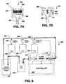
- a recirculating fluid distribution system 300 is illustrated in Figure 6 .
- the distribution system 300 includes a Coriolis flowmeter 312 having a flow tube made of a high purity plastic material as discussed above.
- the flowmeter 312 is in fluid communication with a flow control device, such as a pinch valve 310, and a pressure transmitter 330.
- a controller 314 receives measurement signals from the flowmeter 312 and the pressure transmitter 330, and provides a control signal to the valve 310.
- the controller 314, Coriolis flowmeter 312, pressure transducer 330 and valve 310 may be individual components, or may be combined as an integral flow and pressure control system.
- a reservoir 316 contains fluid to be delivered to a plurality of tool drops 350 via a conduit 351.
- the tool drops 350 are each connectable to a respective tool 352 such as a cleaning, etching or CMP tool to provide fluid to the tool 352.
- a distribution module 354, such as a pump, circulates fluid from the reservoir 316 through the system 300.
- an inert gas such as nitrogen may be supplied to the reservoir 316 to pressurize the reservoir 316 and circulate the fluid.
- the Coriolis mass flowmeter 312 allows a user to monitor flow rate in the system 300. Via the mass flow and pressure control system, a minimum pressure can be maintained at each of the tool drops 350 to eliminate pressure based dispense fluctuations that could affect the performance of the associated tools 352.
- a miniaturized version of the pressure/flow controller can be used to maintain a pressure and mass flow rate to each tool to compensate for variations in loop pressure. Such pressure/flow controllers associated with each tool could be individually operated, or the controller 314 could act as a master controller.
- the Coriolis mass flowmeter 312 can provide a density measurement which can be used as a feedback of the actual blend concentration when the blend is a binary solution of a heavy component such as an acid with water. Solids concentration in a slurry can also be monitored using the density measurement. paste
- FIG. 7A schematically illustrates a high purity pressure transmitter 330 with the wetted process connection including the pressure diaphragm constructed out of a single piece of high purity plastic.
- a key requirement of any instrumentation used in a high purity distribution system is that none of the devices can be a source of leaks. Threaded connections are avoided; the preferred method of making process connections is the use of a face to face seal. Fabricating the process connection 360 out of a single piece of plastic assures that there are no threaded connections, which can be a source of leaks.
- the pressure transmitter 330 includes a sensor holder 358, which may be constructed of polypropylene since it is not part of the flow path.
- a pressure chamber 360 constructed of a high purity material such as PFA is nested in the sensor holder 358.
- the pressure chamber 360 defines a process fluid in-take guide 361 extending therefrom.
- a ceramic pressure sensor 362 is bonded to a high purity diaphragm 364 (for example, 1 mm thick PFA) and any relaxation of the plastic (also called creep) is compensated for by elastomer o-rings 366 situated on top of the ceramic sensor 362, which maintains the ceramic sensor against the plastic diaphragm 364 with a constant force. In this manner, the entire wetted part of the pressure transmitter 330 is PFA or another suitable high purity plastic material.
- FIG. 7B An alternative pressure sensor 331 is shown in Figure 7B .
- the pressure sensor 331 uses a small capacitance pressure sensor 370 constructed from sapphire.
- the sensor is encapsulated in a high purity material such as PFA 372 and extends into the pressure chamber 360 in such a way that the fluid pressure squeezes the sensor 370.
- An advantage of the approach shown in Figure 8B is no fixed reference, such as a sturdy structure, is required for accurate pressure measurement.
- the encapsulated pressure sensor 370 is an integral part of the pressure chamber 360 and is constructed out of a single piece of high purity plastic.
- FIG 8 is a block diagram conceptually illustrating aspects of a high purity fluid delivery system 400 for a CMP process tool in accordance with aspects of the invention.
- the delivery system 400 provides various fluids, for example, water 420, surfactant or reactive agent 421 and slurry 422, to a process tool 452 for application to a semiconductor wafer.
- the tool typically includes a wafer support and a polishing pad.
- Peristaltic pumps 411 are in communication with each of the fluid sources 420,421,422 to pump the respective fluids to the tool 452.
- high purity Coriolis flowmeters 412 are placed in-line with each fluid source to provide mass flow rate feedback.
- a closed loop system can then be achieved through the use of control electronics and/or software, such as a PID controller.
- control valves 410 such as the pinch valve disclosed herein above, are used in conjunction with the high purity Coriolis mass flowmeters 412 to achieve high purity, closed loop control in a CMP process.
- the process tool 452 could supply an on-off signal to each individual fluid control loop if the control loops are set at a desired flowrate.
- the CMP process tool 452 could command a particular flow rate by using, for example, standard industry protocols such as a 4-20mA signal, to each controller. As in the system 300 shown in Figure 6 , the CMP tool could merely command a different recipe and the controller 314 device would control the delivery rates. The main controller 314 sets flow rates and fluid ratios in real-time as necessary.
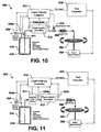
- Figure 10 shows a closed-loop fluid delivery system 500 for a spin-on process used in a photoresist or dielectric liquid application process.
- a reservoir 518 is pressurized with an inert gas, such as nitrogen, which is supplied via a supply conduit.
- the process fluid in the reservoir 518 may be contained within a polymer bag 519 to isolate the fluid from the pressurizing gas.
- a diaphragm may be used to isolate the process fluid from the gas.
- a pressure control valve 550 is located within the inert gas supply conduit to controllably adjust the inert gas being supplied to the reservoir 518.
- the pressure control valve 550 is capable of receiving an output signal from a liquid delivery controller 514 that adjusts the position of the valve 550 from open to close based on a pressure signal received from a first pressure transmitter 530a.
- the controller 514 adjusts the position of the pressure control valve 550 to increase or decrease the pressure of the reservoir 518, based on a predetermined pressure setpoint compared to the output of the pressure transmitter 530a.
- the reservoir 518 is connected to a high purity Coriolis mass flowmeter 512 via an outlet conduit, through which the process fluid exits the reservoir 518.
- a point of use filter 560 is provided to filter process fluid being applied to a spinning work piece 562, which is controlled by a spin controller 564.
- the Coriolis flowmeter 512 in the flow path measures the actual flow rate and provides a signal to the liquid delivery controller 514. If the flow of fluid is low the pressure applied to the liquid inside the reservoir 518 is increased to provide more flow. Increased pressure for liquid delivery may be necessary due to plugging of the point of use filter 560 or in the tubing carrying the liquid. Second and third pressure sensors 530b,530c upstream and downstream of the flowmeter 512 measure the differential pressure required to drive the liquid through the flowmeter 512. The flow rate and differential pressure measurements provided by the flowmeter 512 and pressure sensors 530b,530c can be used to determine the viscosity of the fluid, since the length of the tube is known. The viscosity measurement would indicate any changes to the chemical structure of the fluid.
- a control valve 510 controls the flow rate of the process fluid via control signals from the liquid delivery controller 514. A stepper driven valve would maintain last position.
- a tool controller 515 which may be the same controller as the liquid delivery controller 514 or a separate controller, provides control signals to the spin controller 564 and also provides a flow setpoint to the delivery controller 514.
- a fast acting fluid on/off valve 509 is further provided at the outlet of the reservoir 518 in some embodiments, which is activated by the liquid delivery controller 514 to turn flow on/off based on the requirements from the tool controller 515.
- the liquid delivery controller 514 maintains in memory a table of liquid delivery pressure and flow rates as would be provided by the pressure sensor 530b and Coriolis flowmeter 512, respectively, correlated with various positions of the control valve 510. Based on fluid demand requirements from the tool controller 515, the liquid delivery controller 514 provides optimal settings of pressure on the fluid and control valve settings to provide the proper amount of fluid during the time the valve 509 is open.
- FIG. 11 An alternative spin-on fluid delivery system 501 is shown in Figure 11 .
- the Coriolis flowmeter 512 is downstream of a metering pump 511 to act as a feedback mechanism to assure that the proper amount of liquid is being applied to the work piece 562.
- Prior art metering pump systems are typically open loop, and any plugging of the system downstream of the pump that increases the head pressure will change the fluid delivery to the work piece.
- the signal from the Coriolis flowmeter 512 allows the liquid delivery controller 514 to change the operation of the pump 511 to provide a higher output pressure to compensate for the increased head pressure.
Description
- This application is related to U. S. Patent Applications entitled "High Purity Coriolis Mass Flow Controller," "Flowmeter for the Precision Measurement of an Ultra-Pure Material Flow," "Methods of Manufacturing a PFA Coriolis Flowmeter," "Manufacturing Mass Flow Meters Having a Flow Tube Made of a Fluoropolymer Substance" and "Compensation Method for a PEA Coriolis Flowmeter," each filed on the same day as this application.
- The present invention relates generally to fluid delivery systems, and more particularly, to improved fluid delivery systems and methods that are suitable for the direct application of ultra-pure fluids to a wafer surface in processes such as CMP, photolithography and dielectric processes.
- Many industries such as semiconductor, pharmaceutical, and bio-technology experience fluid delivery problems due to the typically low flow rates, the use of abrasive and aggressive chemical fluids, and the need for contaminant free, accurate, compact, and real-time fluid delivery and/or blending systems.
- Generally the semiconductor industry uses the word "tool" to refer to a system comprised of pieces of hardware that perform an operation on a wafer surface. These operations include the creation of thin films with some form of chemical deposition or fluid coating process, the etching of films in precise patterns, the polishing of films to reduce deposited films to a planar surface and the cleaning of surfaces to remove unneeded films, particles and chemical contaminants. The tool can either be stand alone or incorporated with other tools in a cluster structure where multiple sequential operations on the wafer are done in one location.
- For example, Chemical-Mechanical Planarization (CMP) is a critical process in the semiconductor industry that involves a process to flatten the wafer surface of a semiconductor by applying an ultra-pure fluid containing small abrasive particles and a reactive agent between the wafer surface and a polishing pad. In most applications, the polishing pad rotates at a controlled speed against the wafer to flatten the surface. Over-polishing the wafer can result in altering or removing critical wafer structures. Conversely, under-polishing of the wafer can result in an unacceptable wafer surface. The polishing rate of the wafer is highly dependent upon the delivery rate of the fluid and the total amount of fluid delivered during a polishing operation.
- In addition to fluid flow rate, prevention of contaminants in the fluid being applied to the polishing pad is critical. It is a problem in some applications that the instruments used to control the process are a source of contaminants to the process material. This is undesirable for use in systems where material an ultra high of purity must be delivered to a user's application. For example, the metal flow tube of a typical Coriolis flowmeter can be a source of contaminates. This is the case in the fabrication of semi-conductor wafers, which requires the use of material that is free of contaminants including ions migrating from the flow tube wall. This released material can cause the chips on a semi-conductor wafer to be defective. The same is true for a glass flow tube, which can release the leaded ions from the glass into the material flow. The same is also true for the flow tubes formed of conventional plastics.
- Because prevention of ionic contaminants is critical, the majority of CMP processes utilize peristaltic pumps along with a suitable high purity tubing material to supply fluid to the polishing pad. While the clean flow path non-intrusive characteristic of peristaltic pumps is acceptable for CMP applications, the use of these pumps to attempt to control fluid flow rate is very inaccurate since they are operated open-loop with no flow measurement feedback
- Another process used in the semiconductor industry requiring accurate control of fluid flows and a contaminant free environment is the photolithography process. As is known in the art, photolithography is a process that applies a light sensitive polymer, known as resist, to the wafer surface. A photomask containing a pattern of the structures to be fabricated on the wafer surface is placed between the resist covered wafer and a light source. The light reacts with the resist by either weakening or strengthening the resist polymer. After the resist is exposed to light, the wafer is developed with the application of fluid chemicals that remove the weakened resist.
- A modification of this process applies a host of new liquids to the wafer surface to create films that will become an integral part of the final semiconductor. The primary function of these films is to act as an insulator between electrical conducting wires. A variety of "spin-on" materials are being evaluated with a wide variety of chemical compositions and physical properties. The key difference between the lithography process and the spin-on deposition is that any defect in the film (such as a void, bubble or particle) is now permanently embedded in the structure of the semiconductor and could result in non-functioning devices and a financial loss for the semiconductor producer.
- Both of these processes take place in a tool called a "track." The purpose of the track is to apply a precise volume of fluid to the surface of a stationary or slowly spinning wafer. After the liquid application, the wafer rotation speed is rapidly increased and the liquid on the wafer surface is spun off the edge. A very thin, consistent thickness of liquid remains from the center of the wafer to the edge. Some of the variables that affect liquid thickness include the resist or dielectric viscosity, solvent concentration in the resist or dielectric, the amount of resist/dielectric dispensed, speed of dispense, etc.
- The track will also provide additional processing steps after liquid application that changes the liquid to a polymer using a bake process that also removes any solvent in the film. Dielectric films can also be exposed to other chemical treatments to convert the liquid film to the proper solid structure. The track also controls the environment around the wafer to prevent changes in humidity or temperature and chemical contaminants from affecting the performance of the film. Track system performance is determined by the accuracy and repeatability of liquid delivered to the wafer surface in addition to minimizing defects in the film caused by voids, bubbles and particles.
- Problems associated with currently available fluid delivery systems used in processes such as CMP and spin-on applications include the inability to provide closed loop flow measurement, the inability to provide an accurate fluid delivery rate based on changing head pressure of the pump system, variances in the volume of tubing used in the pump, and pulsations from the pump. Further, periodic weekly or even daily calibration of the pump may be required. Other problems associated with current fluid delivery systems involve contamination of the fluid from shedding tubing particles.
- Additional factors typically important in these industries include the need for real-time fluid property data such as flow rate, fluid temperature, viscosity, density and pressure. While all of the foregoing fluid properties can be measured using a combination of various instruments such as differential pressure transmitters, viscometers, densitometers, pressure transmitters, temperature elements or a combination of the instruments and a control system to calculate the fluid property values, the use these instruments can be expensive, have significant space requirements, require increased maintenance, and provide a greater potential for fluid leakage and process contamination. Therefore, there is a need for an efficient, compact and contaminant free solution to fluid delivery systems in the foregoing industries.
- In other processes there is an increased need for a real-time blending system of multiple fluids requiring a high-purity flow path. In addition, blending based on a volumetric basis is generally unacceptable since typical blending formulas are based on molar ratios. Current blending methods include adding multiple fluids to a container on a weigh scale in an off-line manner, as shown in
Figure 1 . Multiple fluids, A through N, flow into acontainer 11 placed on ascale 12. One fluid is allowed to run through aflow valve 13 at a time. The scale total is examined and when the desired amount of Fluid A has been added, thevalve 13 is closed. The same process is repeated with the remaining fluids. Eventually, a total mixture is obtained. If too much or too little of any fluid has been added the process must continue until the proper mass of each fluid, within some acceptable error band, has been added. - Another known approach uses a level sensor to measure the volume of each fluid of the blend as it is being added to the vessel. This requires a very precise knowledge of the volume of the vessel with small increments of vessel height.
- Unfortunately, the current batch production method can result in too much or too little of the final product being available when needed. Since having too little product available would shut a process down, extra product is always produced, meaning some product will be left over and not used. Since these products often have a limited shelf life (e. g. several hours) this excess product must be disposed of. This disposal is costly for several reasons. The product typically uses very expensive chemicals, and the fluid mixture can often be very hazardous meaning it must be disposed of in a controlled and costly manner.
- As technology develops, the need for manipulation of the blending formulas based on the differences in the product requirements and additional new material components continues to increase, thus requiring a greater need for flexible, accurate and contaminant free real-time continuous blending systems. Another important factor includes the need for accurate pressure control to ensure proper blending and accurate fluid flow rates to the processing tool.
- Thus, there is a need for fluid delivery systems that address shortcomings associated with the prior art.
-
WO 98/14305 -
EP 772,027 A - In one aspect of the present invention a fluid delivery system includes a flow control device, a Coriolis mass flowmeter having a flow-tube made of a high-purity plastic material, and a controller, such as a PID controller. The Coriolis flowmeter provides output signals to the controller indicating, for example, mass flow rate, temperature, and/or density measurements of a process fluid. The control device receives a setpoint signal and the flowmeter output signals, and provides a control output signal to the flow control device to vary the control device's output in order to provide the desired flow rate for the fluid delivery system.
- The Coriolis mass flowmeter's flow-tube is made of the high-purity plastic material to prevent transferring unwanted (e.g. metal) ions to the process fluid. Perfluoralky (PFA) plastic is a suitable material for the flow tube. The flow control device may be embodied by, for example, a control valve, a pump, or a controlled pressurized reservoir. In exemplary embodiments, the control valve is a pinch valve having a solenoid or stepper motor actuator.
- In accordance with other aspects of the invention, a recirculating fluid distribution system includes a fluid reservoir and a distribution conduit in fluid communication with the reservoir. The distribution conduit has a plurality of tool drops for providing fluid from the reservoir to tools attached to the tool drops. A flow control device, such as a variable output pump or a pinch valve, is in fluid communication with a Coriolis mass flowmeter that has a flow-tube made of a high-purity plastic material. A pressure transmitter is in fluid communication with the Coriolis mass flowmeter. A controller receives a setpoint signal and output signals from the Coriolis flowmeter and the pressure transmitter, and provides a control output signal to the flow control device to vary the flow control device output to maintain a predetermined pressure and flow rate in the distribution conduit.
- In accordance with still further aspects of the invention, a fluid delivery system, includes a reservoir having an inlet for receiving a gas to pressurize the reservoir and an outlet for dispensing fluid contained in the reservoir. A first flow control device is connected to the reservoir inlet and a second flow control device is in fluid communication with the reservoir outlet to control fluid flow out of the reservoir. A Coriolis mass flowmeter is in fluid communication with the second flow control device. The Coriolis flowmeter has a flow-tube made of a high-purity plastic material, such as PFA. A controller receives a setpoint signal and output signals from the Coriolis flowmeter, and provides control output signals to the first and second flow control devices to vary the pressure of the reservoir and the flow rate of fluid from the reservoir.
- According to one aspect a recirculating fluid distribution system comprises:
- a fluid reservoir;
- a distribution conduit in fluid communication with the reservoir, the distribution conduit having a plurality of tool drops for providing fluid from the reservoir to tools attached to the tool drops;
- a flow control device;
- characterized by:
- a Coriolis mass flowmeter in fluid communication with the flow control device, the Coriolis flowmeter having a flow-tube made of a high-purity plastic material, the Coriolis flowmeter providing an output signal;
- a pressure transmitter in fluid communication with the Coriolis mass flowmeter, the pressure transmitter providing an output signal;
- a controller receiving a setpoint signal, the controller receiving the output signals from the Coriolis flowmeter and the pressure transmitter and providing a control output signal to the flow control device, wherein the flow control device output varies in response to the control output signal to maintain a predetermined pressure and flow rate in the distribution conduit;
- a plurality of tool drop flow control devices, each of the tool drop flow control devices being in-line with a respective tool drop; and
- a plurality of tool drop Coriolis mass flowmeters, each of the tool drop Coriolis mass flowmeters being in-line with a respective tool drop, the tool drop Coriolis mass flowmeters each having a flow-tube made of a high-purity plastic material, the tool drop Coriolis mass flowmeters each providing an output signal;
- wherein the controller receives the output signals from the tool drop Coriolis mass flowmeters and provides control signals to the tool drop flow control devices.
- Preferably, the recirculating fluid distribution system further comprises a plurality of tool drop controller, each of the tool drop controllers being associated with a respective tool drop flow control device and a tool drop Coriolis mass flow meter, each tool drop controller receiving the output signal from the associated tool drop Coriolis mass flowmeters and providing control signals to the associated tool drop flow control devices.
- Preferably, the flow control device comprises a pinch valve.
- Preferably, the pressure transmitter comprises:
- a sensor holder;
- a pressure chamber including a diaphragm situation in the sensor holder, the pressure chamber and diaphragm constructed of a high purity plastic;
- a pressure sensor bonded to the diaphragm; and
- an o-ring situated between the diaphragm and the sensor holder.
- Preferably, the pressure transmitter comprises:
- a sensor holder;
- a pressure chamber situated in the sensor holder;
- a pressure sensor encapsulated in a high purity plastic material extending into the pressure chamber.
- Preferably, the pressure sensor is constructed from sapphire.
- Other objects and advantages of the invention will become apparent upon reading the following detailed description and upon reference to the drawings in which:
-
Figure 1 schematically illustrates a prior art off-line blending system; -
Figure 2 is a block diagram schematically illustrating a fluid delivery system in accordance with the present invention; -
Figure 3 is a perspective view of a Coriolis flowmeter having a high purity flow tube suitable for use in the various embodiments of the present invention; -
Figure 4 schematically illustrates a pinch valve in accordance with the present invention; -
Figure 5 is a block diagram illustrating aspects of a real-time, high purity blending system in accordance with embodiments of the present invention; -
Figure 6 is a block diagram illustrating a recirculating fluid distribution system in accordance with embodiments of the present invention; -
Figure 7A schematically illustrates a high purity pressure transmitter in accordance with aspects of the present invention; -
Figure 7B illustrates an alternative embodiment of a high purity pressure transducer containing an encapsulated sapphire sensor; -
Figure 8 is a block diagram conceptually illustrating aspects of a high purity fluid delivery system for a CMP process tool in accordance with embodiments of the present invention; -
Figure 9 is a block diagram conceptually illustrating aspects of an alternative high purity fluid delivery system for a CMP process tool in accordance with embodiments of the present invention; -
Figure 10 is a block diagram illustrating a closed-loop fluid delivery system for a spin-on process in accordance with embodiments of the present invention; and -
Figure 11 is a block diagram illustrating an alternative closed-loop fluid delivery system for a spin-on process in accordance with embodiments of the present invention. - While the invention is susceptible to various modifications and alternative forms, specific embodiments thereof have been shown by way of example in the drawings and are herein described in detail.
- Illustrative embodiments of the invention are described below. In the interest of clarity, not all features of an actual implementation are described in this specification. It will of course be appreciated that in the development of any such actual embodiment, numerous implementation-specific decisions must be made to achieve the developers' specific goals, such as compliance with system-related and business-related constraints, which will vary from one implementation to another. Moreover, it will be appreciated that such a development effort might be complex and time-consuming, but would nevertheless be a routine undertaking for those of ordinary skill in the art having the benefit of this disclosure.
-
Figure 2 schematically illustrates afluid delivery system 100 in accordance with exemplary embodiments of the invention. The mass flow-baseddelivery system 100 is suitable, for example, to control the flow of fluid to a tool or a work piece supported by a tool, such as a polishing pad of a CMP system or a track used for semiconductor spin-on applications. In general, thesystem 100 includes aflow control device 110, amass flowmeter 112, and acontroller 114. - The
controller 114 receives a setpoint signal representing a desired parameter, such as mass flow rate. Thecontroller 114 also receives an output signal from theflowmeter 112. The flowmeter signal is conditioned and processed by thecontroller 114, which then provides a control output signal to theflow control device 110 so as to vary the fluid flow rate. Thecontroller 114 is electronic and has an electronic interface, and may comprise, for example, a proportional-integral-derivative (PID) controller. The setpoint input to thecontroller 114 is typically an electronic signal, such as a 0-5V, 4-20mA signal or a digital word. A pneumatic setpoint interface could also be used. Thecontroller 114 may also include a valve override feature, where an additional signal is sent into thecontroller 114 that causes thecontroller 114 to ignore the setpoint and fully open or close theflow control device 110. This feature is often used for shutting the flow off or purging the system. - In certain embodiments, such as fluid delivery systems for chemical blending applications, the
mass flowmeter 112 is preferably a Coriolis mass flowmeter. A direct mass flowmeter is generally preferable over a volumetric flowmeter since the desired chemical reactions typically are driven on a mole (mass) basis. Volumetric flow rate measurements can be made and corrected to standard conditions resulting in the equivalent of a mass measurement. However, additional information is required (fluid density, temperature, and/or pressure) making the measurement more difficult and costly. Mass flow rate measurements are typically more accurate than volumetric measurements which are converted to a mass measurement and, this accuracy results in a higher quality final product. This would increase the process yield and thus improve the profitability of companies utilizing this invention. - Many applications, such as those associated with the semiconductor, pharmaceutical, and bio-technology industries, require the flow path (all surfaces wetted by the process fluid) of fluid delivery systems be constructed of high purity, chemically inert/resistant, materials to protect the purity of the chemicals used. Plastics are desirable because the ultra pure chemicals used in the semiconductor wafer fabrication processes can be contaminated if metal ions are leached or removed from metal flow tubes due to a variety of mechanical and chemical processes. High purity grade plastics are thus used in these industries since this generally prevents transferring unwanted (e.g. metal) ions to the process material. In addition, the smooth surface finish inherent in the manufacturing of a plastic flow tube reduces the ability of bacteria to attach to the tube and contaminate the fluid with organic materials.
- The wetted path of the
flowmeter 112 is designed such that it has no cracks, crevices, etc. that could harbor bacteria. A suitable high purity plastic is PFA (perfluoroalkoxy copolymer), which is an advanced fluoropolymer with superior chemical resistance and mechanical properties. A variety of fluorinated polymers such PVDF and PTFE are also suitable. - In addition to using high purity materials, the high purity flow path should have a constant diameter and no intrusions or multiple flow paths - a dual tube sensor or a curved flow path should be avoided. This minimizes pressure drop, reduces the shear rate on the fluid to a minimum, which is critical in some industries and applications. It also prevents plugging with certain materials, such as slurries.
- A suitable Coriolis mass flowmeter having a flow-tube made of a high-purity plastic material is shown in
Figure 3 . TheCoriolis flowmeter 50 has aflow tube 52 inserted throughlegs 67, 68 of abase 51. Theflow tube 52 is preferably made of PFA. Pick offs LPO and RP0 and a driver D are coupled to theflow tube 52. Theflowmeter 50 receives a process material flow from asupply tube 54 and extends the flow through aconnector 58 to theflow tube 52. Theflow tube 52 is vibrated at its resonant frequency with material flow by the driver D. The resulting Coriolis deflections are detected by pick offs LPO and RP0 which apply signals overconductors 62 and 64 to meter electronics (not shown), which determines the phase difference between the Coriolis deflections and applies output signals based thereon. Suitable Coriolis flowmeters having high purity flow tubes are disclosed in detail in the incorporated application entitled "Flowmeter for the Precision Measurement of an Ultra-Pure Material Flow." - The
flow control device 110 may comprise a control valve. As with themass flowmeter 112, in high purity applications the control device must be made of materials that will minimize contamination of the fluid. Moreover, thecontrol device 110 should be designed to have no places where stagnant fluid can collect and no sliding or rubbing parts that could create particles in the fluid. - For example, an all-plastic diaphragm valve made from plastics that are acceptable in high purity chemical environments could be used. For slurries, however, such a valve is not the ideal solution. Pinch valves have proven to be a good solution to slurry control. A
suitable pinch valve 120 in accordance with the present invention is conceptually illustrated inFigure 4 . Anactuator 122 forces aram 124 onto aflexible tube 126 and against areference surface 128 to pinch thetube 126 closed. Thetube 126 is preferably made of a high purity plastic such as PFA. The tube's flexibility allows the tubing walls to conform around any trapped particles or imperfections in the walls to provide a tight seal. The flow path is straight through, minimizing pressure drop and turbulence. The fluid contacts only theflow tube 126 preventing wear or corrosion of the other valve parts and preventing metal contamination of the slurry in the case of high purity applications, such as semiconductor polishing operations. - The actuation of known pinch valves is usually bi-stable - on and off. Some known pinch valves have a manual actuator with a multi-turn handle, but this type of valve would not be conducive to closed loop flow control. Other pinch valves are used for dispensing applications in batch processes, in which the amount of material dispensed is controlled by the time that the valve is on. This does not allow dynamically controlling the flow rate.
- A valve that has only two states can be controlled by applying varying current or voltage to the valve actuator. In one embodiment, pulse-width modulation (PWM) is used to control the valve. PWM is achieved by generating a square wave signal at a frequency above the valve's mechanical response frequency. The duty cycle of the signal is varied to determine the appropriate voltage or current sent to the device. For example, if the PWM signal operates between 0-12 volts, 0% duty cycle = 0 volts, 50% duty cycle = 6 volts, and 100% duty cycle = 12 volts. The "averaging" takes place because the signal is at a frequency above the valve's mechanical response frequency. The position of the valve is based on the average current that is supplied. The resulting supply voltage is proportional to the pulse width of the signal.
- If the signal frequency is too low, the valve will have time to respond completely to on and off signals creating a pulsed flow output, which is generally not desirable. A typical pinch valve actuator is a solenoid, which has a spring element with a preload adjustment that determines the current required to close the solenoid. Adjusting the pre-load on the valve spring can improve the valve's control range. In other implementations, the solenoid plunger element is replaced with a spring-suspended plunger. The spring-suspended plunger minimizes the non-linear valve response due to friction, which minimizes the hysteresis and dead band common in available solenoid-actuated pinch valves.
- An alternative approach to the PWM-controlled solenoid is to use a stepper motor actuator, which translates a controlled, deterministic angular rotation to a linear ram drive by a worm gear type arrangement. Stepper controllers can be designed to produce a specific number of steps proportional to an analog signal input. Backlash, and thus valve hysteresis can be minimized by any number of appropriate worm gear designs that minimize backlash. A stepper motor generally provides immunity to temperature and pressure fluctuations, which may cause changes in the pinch tubing. A stepper motor is a means to control position, so the stepper is immune changes in the pinch tubing. With a pinch valve, the pinch tube is an integral part of the system - current is applied to the valve actuator, which applies force to the pinch tube, which pinches the tube. If the tube properties change due to temperature or pressure, the amount the tube closes, and thus the flow rate with a solenoid, changes. Moreover, a stepper actuator can remain at the last position to provide fast response to achieving setpoint at the start of a fluid delivery cycle.
- The
Coriolis flowmeter 112 and flowcontrol device 110 may be configured as an integral unit, housed in asingle enclosure 116, and additionally thecontroller 114 may also be housed in thesame enclosure 116 to provide an integrated high purity, Coriolis mass flow controller. A suitable high purity, Coriolis mass flow controller is disclosed in additional detail in the incorporated application entitled "High Purity Coriolis Mass Flow Controller." - Alternatively, the
flow control device 110 may comprise a variable output pump, such as a peristaltic pump. In still further embodiments, a pressurized vessel or reservoir in which the pressure is varied to change the flow rate of fluid dispensed from the vessel functions as theflow control device 110. For example, referring toFigure 2 , afluid reservoir 118 may be variably pressurized to vary the flow rate of fluid exiting thereservoir 118. Controlling the fluid flow rate in this manner may be in addition to, or in place of, the illustratedflow control device 110. Such alternative flow control devices are discussed in further detail herein below in conjunction with further exemplary embodiments of the invention. -
Figure 5 illustrates a real-time blending system 200 in accordance with aspects of the present invention. The illustrated system is high purity, corrosion resistant and mass based to address shortcomings associated with the prior art. At least two key factors are needed to achieve these features. One is a high purity flow path, and another is a mass flow rate measurement. Accordingly, thesystem 200 includesCoriolis flowmeters 212 having high purity plastic flow tubes as described above. TheCoriolis flowmeters 212 provide a density measurement that may be used as a feedback of the actual blend concentration when the blend is a binary solution of a heavy component such as an acid with water. Solids concentration in a slurry can also be monitored using the density measurement. In addition to mass flow rate and density, theflowmeters 212 may be configured to provide additional measurement output signals, such as a temperature measurement. - Using the
mass flowmeters 212 allows real-time, on-line blending of multiple fluid streams 220. As noted above, a mass flow rate measurement is preferred over a volumetric flow rate measurement since the desired chemical reactions are typically driven on a mole (mass) basis. - The real
time blending system 200 further includesflow control devices 210, such as the pinch valves described above. Theflowmeters 212 provide output signals indicative of, for example, fluid flow rate, temperature and density to thecontroller 214. Based on pre-determined or real-time fluid stream flow rate setpoint parameters, thecontroller 214 sends control signals to theflow control devices 210 in order to supply the desired amount of blended fluid to a work piece. In this manner, thevarious fluids 220 are merged to form a single fluid stream that is provided to acommon conduit 216. A mixingchamber 218 may further be provided to achieve complete blending of thefluids 220. Additionally, check valves (not shown) may be provided to ensure theindividual fluid streams 220 are not contaminated due to variations in fluid stream supply pressures. - A man-machine-interface (MMI) may further be provided. The MMI provides an interface that, for example, communicates the values and status of input and output signals as well as providing predetermined alarms when the value of a programmed input signal or other measurement falls outside of an accepted range of values. In addition, the input and output signals between the various components of the
system 200 can all be connected over a single pair fieldbus cable. Further, in certain embodiments, the system is also capable of calibration, testing and maintenance of the system via thecontroller 214, as well as configuration and selection of the pre-configured blending recipes. While thesystem 200 invention as illustrated inFigure 4 shows theflowmeter 212,flow control device 210 andcontroller 214 as separate components, it should be appreciated that various combinations of these components may be configured as an integral unit in a common enclosure. - A recirculating
fluid distribution system 300 is illustrated inFigure 6 . Thedistribution system 300 includes a Coriolis flowmeter 312 having a flow tube made of a high purity plastic material as discussed above. The flowmeter 312 is in fluid communication with a flow control device, such as apinch valve 310, and apressure transmitter 330. Acontroller 314 receives measurement signals from the flowmeter 312 and thepressure transmitter 330, and provides a control signal to thevalve 310. Thecontroller 314, Coriolis flowmeter 312,pressure transducer 330 andvalve 310 may be individual components, or may be combined as an integral flow and pressure control system. - A
reservoir 316 contains fluid to be delivered to a plurality of tool drops 350 via aconduit 351. The tool drops 350 are each connectable to arespective tool 352 such as a cleaning, etching or CMP tool to provide fluid to thetool 352. Adistribution module 354, such as a pump, circulates fluid from thereservoir 316 through thesystem 300. Alternatively, an inert gas such as nitrogen may be supplied to thereservoir 316 to pressurize thereservoir 316 and circulate the fluid. - The Coriolis mass flowmeter 312 allows a user to monitor flow rate in the
system 300. Via the mass flow and pressure control system, a minimum pressure can be maintained at each of the tool drops 350 to eliminate pressure based dispense fluctuations that could affect the performance of the associatedtools 352. A miniaturized version of the pressure/flow controller can be used to maintain a pressure and mass flow rate to each tool to compensate for variations in loop pressure. Such pressure/flow controllers associated with each tool could be individually operated, or thecontroller 314 could act as a master controller. - As noted above, the Coriolis mass flowmeter 312 can provide a density measurement which can be used as a feedback of the actual blend concentration when the blend is a binary solution of a heavy component such as an acid with water. Solids concentration in a slurry can also be monitored using the density measurement.
paste - As noted above, to achieve a high purity system the entire flow path must be made of a high purity, chemically inert/resistant material.
Figure 7A schematically illustrates a highpurity pressure transmitter 330 with the wetted process connection including the pressure diaphragm constructed out of a single piece of high purity plastic. A key requirement of any instrumentation used in a high purity distribution system is that none of the devices can be a source of leaks. Threaded connections are avoided; the preferred method of making process connections is the use of a face to face seal. Fabricating theprocess connection 360 out of a single piece of plastic assures that there are no threaded connections, which can be a source of leaks. - The
pressure transmitter 330 includes asensor holder 358, which may be constructed of polypropylene since it is not part of the flow path. Apressure chamber 360 constructed of a high purity material such as PFA is nested in thesensor holder 358. Thepressure chamber 360 defines a process fluid in-take guide 361 extending therefrom. To provide stable pressure measurement performance, aceramic pressure sensor 362 is bonded to a high purity diaphragm 364 (for example, 1 mm thick PFA) and any relaxation of the plastic (also called creep) is compensated for by elastomer o-rings 366 situated on top of theceramic sensor 362, which maintains the ceramic sensor against theplastic diaphragm 364 with a constant force. In this manner, the entire wetted part of thepressure transmitter 330 is PFA or another suitable high purity plastic material. - An alternative pressure sensor 331 is shown in
Figure 7B . The pressure sensor 331 uses a smallcapacitance pressure sensor 370 constructed from sapphire. The sensor is encapsulated in a high purity material such asPFA 372 and extends into thepressure chamber 360 in such a way that the fluid pressure squeezes thesensor 370. An advantage of the approach shown in Figure 8B is no fixed reference, such as a sturdy structure, is required for accurate pressure measurement. The encapsulatedpressure sensor 370 is an integral part of thepressure chamber 360 and is constructed out of a single piece of high purity plastic. -
Figure 8 is a block diagram conceptually illustrating aspects of a high purityfluid delivery system 400 for a CMP process tool in accordance with aspects of the invention. Thedelivery system 400 provides various fluids, for example,water 420, surfactant orreactive agent 421 andslurry 422, to aprocess tool 452 for application to a semiconductor wafer. The tool typically includes a wafer support and a polishing pad.Peristaltic pumps 411 are in communication with each of the fluid sources 420,421,422 to pump the respective fluids to thetool 452. Further, highpurity Coriolis flowmeters 412 are placed in-line with each fluid source to provide mass flow rate feedback. A closed loop system can then be achieved through the use of control electronics and/or software, such as a PID controller. - Another
fluid delivery system 401 is shown inFigure 9 , in which controlvalves 410, such as the pinch valve disclosed herein above, are used in conjunction with the high purity Coriolismass flowmeters 412 to achieve high purity, closed loop control in a CMP process. In certain embodiments, theprocess tool 452 could supply an on-off signal to each individual fluid control loop if the control loops are set at a desired flowrate. - Different wafers, however, may need to be processed differently and thus require a different "recipe" of fluids be delivered to the polishing pad. The
CMP process tool 452 could command a particular flow rate by using, for example, standard industry protocols such as a 4-20mA signal, to each controller. As in thesystem 300 shown inFigure 6 , the CMP tool could merely command a different recipe and thecontroller 314 device would control the delivery rates. Themain controller 314 sets flow rates and fluid ratios in real-time as necessary. -
Figure 10 shows a closed-loopfluid delivery system 500 for a spin-on process used in a photoresist or dielectric liquid application process. Areservoir 518 is pressurized with an inert gas, such as nitrogen, which is supplied via a supply conduit. The process fluid in thereservoir 518 may be contained within apolymer bag 519 to isolate the fluid from the pressurizing gas. In other embodiments, a diaphragm may be used to isolate the process fluid from the gas. Apressure control valve 550 is located within the inert gas supply conduit to controllably adjust the inert gas being supplied to thereservoir 518. Thepressure control valve 550 is capable of receiving an output signal from aliquid delivery controller 514 that adjusts the position of thevalve 550 from open to close based on a pressure signal received from afirst pressure transmitter 530a. Thecontroller 514 adjusts the position of thepressure control valve 550 to increase or decrease the pressure of thereservoir 518, based on a predetermined pressure setpoint compared to the output of thepressure transmitter 530a. - The
reservoir 518 is connected to a high purity Coriolismass flowmeter 512 via an outlet conduit, through which the process fluid exits thereservoir 518. A point ofuse filter 560 is provided to filter process fluid being applied to aspinning work piece 562, which is controlled by aspin controller 564. - The
Coriolis flowmeter 512 in the flow path measures the actual flow rate and provides a signal to theliquid delivery controller 514. If the flow of fluid is low the pressure applied to the liquid inside thereservoir 518 is increased to provide more flow. Increased pressure for liquid delivery may be necessary due to plugging of the point ofuse filter 560 or in the tubing carrying the liquid. Second andthird pressure sensors flowmeter 512 measure the differential pressure required to drive the liquid through theflowmeter 512. The flow rate and differential pressure measurements provided by theflowmeter 512 andpressure sensors control valve 510 controls the flow rate of the process fluid via control signals from theliquid delivery controller 514. A stepper driven valve would maintain last position. - A
tool controller 515, which may be the same controller as theliquid delivery controller 514 or a separate controller, provides control signals to thespin controller 564 and also provides a flow setpoint to thedelivery controller 514. A fast acting fluid on/off valve 509 is further provided at the outlet of thereservoir 518 in some embodiments, which is activated by theliquid delivery controller 514 to turn flow on/off based on the requirements from thetool controller 515. Theliquid delivery controller 514 maintains in memory a table of liquid delivery pressure and flow rates as would be provided by thepressure sensor 530b andCoriolis flowmeter 512, respectively, correlated with various positions of thecontrol valve 510. Based on fluid demand requirements from thetool controller 515, theliquid delivery controller 514 provides optimal settings of pressure on the fluid and control valve settings to provide the proper amount of fluid during the time the valve 509 is open. - An alternative spin-on
fluid delivery system 501 is shown inFigure 11 . In thedelivery system 501, theCoriolis flowmeter 512 is downstream of ametering pump 511 to act as a feedback mechanism to assure that the proper amount of liquid is being applied to thework piece 562. Prior art metering pump systems are typically open loop, and any plugging of the system downstream of the pump that increases the head pressure will change the fluid delivery to the work piece. The signal from theCoriolis flowmeter 512 allows theliquid delivery controller 514 to change the operation of thepump 511 to provide a higher output pressure to compensate for the increased head pressure.
Claims (6)
- A recirculating fluid distribution system (300), comprising:a fluid reservoir (316);a distribution conduit (351) in fluid communication with the reservoir (316), the distribution conduit (351) having a plurality of tool drops for providing fluid from the reservoir (316) to tools (352) attached to the tool drops;a flow control device (310);characterized by:a Coriolis mass flowmeter (312) in fluid communication with the flow control device (310), the Coriolis flowmeter (312) having a flow-tube made of a high-purity plastic material, the Coriolis flowmeter (312) providing a output signal;a pressure transmitter (330) in fluid communication with the Coriolis mass flowmeter (312), the pressure transmitter (330) providing an output signal;a controller (314) receiving a setpoint signal, the controller (314) receiving the output signals from the Coriolis flowmeter (312) and the pressure transmitter (330) and providing a control output signal to the flow control device (310), wherein the flow control device (310) output varies in response to the control output signal to maintain a predetermined pressure and flow rate in the distribution conduit (351);a plurality of tool drop flow control devices, each of the tool drop flow control devices being in-line with a respective tool drop; anda plurality of tool drop Coriolis mass flowmeters, each of the tool drop Coriolis mass flowmeters being in-line with a respective tool drop, the tool drop Coriolis mass flowmeters each having a flow-tube made of a high-purity plastic material, the tool drop Coriolis mass flowmeters each providing an output signal;wherein the controller (314) receives the output signals from the tool drop Coriolis mass flowmeters and provides control signals to the tool drop flow control devices.
- The recirculating fluid distribution system (300) of claim 1, further comprising a plurality of tool drop controllers (350), each of the tool drop controllers (350) being associated with a respective tool drop flow control device and a tool drop Coriolis mass flow meter, each tool drop controller (350) receiving the output signal from the associated tool drop Coriolis mass flowmeters and providing control signals to the associated tool drop flow control devices.
- The recirculating fluid distribution system (300) of claim 1, wherein the flow control device (310) comprises a pinch valve.
- The recirculating fluid distribution system (300) of claim 1, wherein the pressure transmitter (330) comprises:a sensor holder (358);a pressure chamber (360) including a diaphragm (364) situation in the sensor holder (358), the pressure chamber (360) and diaphragm (364) constructed of a high purity plastic;a pressure sensor (370) bonded to the diaphragm (364); andan o-ring situated (366) between the diaphragm (364) and the sensor holder (358).
- The recirculating fluid distribution system (300) of claim 1, wherein the pressure transmitter (330) comprises:a sensor holder (358);a pressure chamber (360) situated in the sensor holder (358);a pressure sensor (370) encapsulated in a high purity plastic material extending into the pressure chamber (360).
- The recirculating fluid distribution system (300) of claim 5, wherein the pressure sensor (330) is constructed from sapphire.
Priority Applications (1)
| Application Number | Priority Date | Filing Date | Title |
|---|---|---|---|
| EP20100012728 EP2312277A3 (en) | 2001-11-26 | 2002-11-25 | High purity fluid delivery system |
Applications Claiming Priority (2)
| Application Number | Priority Date | Filing Date | Title |
|---|---|---|---|
| US09/995,067 US20030098069A1 (en) | 2001-11-26 | 2001-11-26 | High purity fluid delivery system |
| EP20020786789 EP1451533B1 (en) | 2001-11-26 | 2002-11-25 | High purity fluid delivery system |
Related Parent Applications (2)
| Application Number | Title | Priority Date | Filing Date |
|---|---|---|---|
| EP20020786789 Division EP1451533B1 (en) | 2001-11-26 | 2002-11-25 | High purity fluid delivery system |
| EP02786789.4 Division | 2002-11-25 |
Related Child Applications (2)
| Application Number | Title | Priority Date | Filing Date |
|---|---|---|---|
| EP10003551.8 Division-Into | 2010-03-31 | ||
| EP10012728.1 Division-Into | 2010-10-01 |
Publications (3)
| Publication Number | Publication Date |
|---|---|
| EP2026041A2 EP2026041A2 (en) | 2009-02-18 |
| EP2026041A3 EP2026041A3 (en) | 2012-02-08 |
| EP2026041B1 true EP2026041B1 (en) | 2013-05-01 |
Family
ID=25541348
Family Applications (3)
| Application Number | Title | Priority Date | Filing Date |
|---|---|---|---|
| EP20100012728 Withdrawn EP2312277A3 (en) | 2001-11-26 | 2002-11-25 | High purity fluid delivery system |
| EP20080166981 Expired - Lifetime EP2026041B1 (en) | 2001-11-26 | 2002-11-25 | High purity fluid delivery system |
| EP20020786789 Expired - Lifetime EP1451533B1 (en) | 2001-11-26 | 2002-11-25 | High purity fluid delivery system |
Family Applications Before (1)
| Application Number | Title | Priority Date | Filing Date |
|---|---|---|---|
| EP20100012728 Withdrawn EP2312277A3 (en) | 2001-11-26 | 2002-11-25 | High purity fluid delivery system |
Family Applications After (1)
| Application Number | Title | Priority Date | Filing Date |
|---|---|---|---|
| EP20020786789 Expired - Lifetime EP1451533B1 (en) | 2001-11-26 | 2002-11-25 | High purity fluid delivery system |
Country Status (17)
| Country | Link |
|---|---|
| US (3) | US20030098069A1 (en) |
| EP (3) | EP2312277A3 (en) |
| JP (2) | JP4294485B2 (en) |
| KR (6) | KR20100061724A (en) |
| CN (1) | CN1310016C (en) |
| AR (1) | AR037441A1 (en) |
| AT (1) | ATE549604T1 (en) |
| AU (1) | AU2002350257B2 (en) |
| BR (1) | BRPI0214113B1 (en) |
| CA (2) | CA2464051C (en) |
| DK (2) | DK1451533T3 (en) |
| HK (1) | HK1127725A1 (en) |
| MX (1) | MXPA04004957A (en) |
| MY (1) | MY131073A (en) |
| PL (1) | PL206930B1 (en) |
| RU (1) | RU2302653C2 (en) |
| WO (1) | WO2003046489A1 (en) |
Families Citing this family (108)
| Publication number | Priority date | Publication date | Assignee | Title |
|---|---|---|---|---|
| JP2002331456A (en) * | 2001-05-08 | 2002-11-19 | Kurita Water Ind Ltd | Recovering device of abrasive |
| US7086933B2 (en) * | 2002-04-22 | 2006-08-08 | Applied Materials, Inc. | Flexible polishing fluid delivery system |
| US7104275B2 (en) * | 2002-04-01 | 2006-09-12 | Emerson Electric Co. | Pinch valve |
| US7188644B2 (en) * | 2002-05-03 | 2007-03-13 | Advanced Technology Materials, Inc. | Apparatus and method for minimizing the generation of particles in ultrapure liquids |
| US6702655B2 (en) * | 2002-07-05 | 2004-03-09 | Taiwan Semiconductor Manufacturing Co., Ltd | Slurry delivery system for chemical mechanical polisher |
| US7299944B2 (en) * | 2002-11-21 | 2007-11-27 | Carrier Commercial Refrigeration, Inc. | Fluid dispenser calibration system and method |
| US6939210B2 (en) * | 2003-05-02 | 2005-09-06 | Applied Materials, Inc. | Slurry delivery arm |
| DE20314772U1 (en) * | 2003-09-22 | 2003-12-04 | Gce-Druva Gmbh & Co. Kg | Gas extraction device, in particular for high-purity gases |
| CN101334305B (en) | 2003-09-29 | 2012-05-09 | 微动公司 | Diagnostic device and method for coriolis flowmeter |
| GB0326726D0 (en) * | 2003-11-18 | 2003-12-17 | Mount Packaging Systems Ltd | Apparatus for dispensing measured batches of liquid |
| FR2874028B1 (en) * | 2004-08-06 | 2006-10-27 | Qualiflow Sa Sa | DEVICE FOR INTRODUCTION IN AN ENCLOSURE OF LIQUID PRECURSORS IN PULSE MODE WITH MEASUREMENT AND CONTROL OF THE FLOW |
| EP1766342A2 (en) * | 2004-07-15 | 2007-03-28 | PDC Facilities, Inc. | Liner for a flow meter |
| US7172096B2 (en) * | 2004-11-15 | 2007-02-06 | Advanced Technology Materials, Inc. | Liquid dispensing system |
| NZ537147A (en) * | 2004-12-13 | 2007-06-29 | Australo Ltd | Method and apparatus for particle analysis |
| SG186677A1 (en) * | 2005-04-25 | 2013-01-30 | Advanced Tech Materials | Liner-based liquid storage and dispensing systems with empty detection capability |
| US7392709B2 (en) * | 2005-05-16 | 2008-07-01 | Endress + Hauser Flowtec Ag | Inline measuring device with a vibration-type measurement pickup |
| EP2388232B9 (en) * | 2005-06-06 | 2019-03-06 | Entegris, Inc. | Process fluid dispensing system and method |
| US7819139B2 (en) * | 2005-07-14 | 2010-10-26 | Pdc Facilities, Inc. | Liner for a flow meter |
| ES2304653T3 (en) * | 2005-07-22 | 2008-10-16 | Kemya Al-Jubail Petrochemical Company | PRESSURE CONTROL SYSTEM. |
| US7484345B2 (en) * | 2005-11-28 | 2009-02-03 | Pdc Facilities, Inc. | Filling machine |
| JP4854330B2 (en) * | 2005-12-02 | 2012-01-18 | 旭有機材工業株式会社 | Fluid mixing device |
| JP4854331B2 (en) * | 2005-12-02 | 2012-01-18 | 旭有機材工業株式会社 | Fluid mixing device |
| US20070131562A1 (en) * | 2005-12-08 | 2007-06-14 | Applied Materials, Inc. | Method and apparatus for planarizing a substrate with low fluid consumption |
| US7818092B2 (en) * | 2006-01-20 | 2010-10-19 | Fisher Controls International Llc | In situ emission measurement for process control equipment |
| US7661439B2 (en) | 2006-02-07 | 2010-02-16 | Dresser, Inc. | Safety override circuit for pneumatic positioner and method of use thereof |
| WO2007101248A2 (en) * | 2006-02-28 | 2007-09-07 | Levtech, Inc. | Disposable pumping apparatus based on flexible vessels in pressurized containers |
| US20070205214A1 (en) * | 2006-03-03 | 2007-09-06 | Roberts Benjamin R | Liquid dispense system |
| US7993600B2 (en) | 2006-03-03 | 2011-08-09 | KBK Technologies Inc. | Salt dispensing system |
| US7954508B2 (en) * | 2006-03-03 | 2011-06-07 | KBK Technologies, Inc. | Electronically controlled valve actuator in a plumbed water line within a water conditioning management system |
| JP4854350B2 (en) * | 2006-03-22 | 2012-01-18 | 旭有機材工業株式会社 | Fluid mixing device |
| EP2069727B1 (en) | 2006-08-24 | 2020-04-29 | Micro Motion Incorporated | Multiple flow conduit flow meter, as well as measurement method and calibration method for such a flow meter |
| US20080163937A1 (en) * | 2007-01-09 | 2008-07-10 | Dresser, Inc. | Fluid regulatory systems and processes |
| US8167004B2 (en) * | 2007-02-14 | 2012-05-01 | Lg Electronics Inc. | Automatic liquid dispensers |
| JP5041847B2 (en) * | 2007-03-30 | 2012-10-03 | 旭有機材工業株式会社 | Fluid control device |
| TW200916183A (en) * | 2007-05-09 | 2009-04-16 | Advanced Tech Materials | Systems and methods for material blending and distribution |
| AU2008335308A1 (en) * | 2007-12-06 | 2009-06-18 | Foresight Processing, Llc | Systems and methods for delivery of fluid-containing process material combinations |
| EP2280903B1 (en) * | 2008-06-03 | 2013-02-13 | Gilbarco Inc. | Dispensing equipment utilizing coriolis flow meters |
| US8561627B1 (en) * | 2008-09-26 | 2013-10-22 | Intermolecular, Inc. | Calibration of a chemical dispense system |
| US10006214B2 (en) | 2009-01-28 | 2018-06-26 | Pentair Water Pool And Spa, Inc. | pH balancing dispenser and system with piercing opener |
| US9416034B2 (en) * | 2009-01-28 | 2016-08-16 | Pentair Water Pool And Spa, Inc. | pH balancing system |
| US20100217536A1 (en) * | 2009-02-26 | 2010-08-26 | Invensys Systems, Inc. | Bunker fuel transfer |
| US8617972B2 (en) | 2009-05-22 | 2013-12-31 | Advanced Technology Materials, Inc. | Low temperature GST process |
| US8813497B2 (en) * | 2009-09-17 | 2014-08-26 | Echogen Power Systems, Llc | Automated mass management control |
| US8746270B2 (en) * | 2010-02-10 | 2014-06-10 | Brg Industries Incorporated | Precision low flow rate fluid delivery system and methods for controlling same |
| US9389111B2 (en) | 2010-03-11 | 2016-07-12 | Measurement Technology Group, Inc. | Dynamic-adaptive vapor reduction system and method |
| KR101706809B1 (en) | 2010-03-26 | 2017-02-15 | 엔테그리스, 아이엔씨. | Germanium antimony telluride materials and devices incorporating same |
| US9190609B2 (en) | 2010-05-21 | 2015-11-17 | Entegris, Inc. | Germanium antimony telluride materials and devices incorporating same |
| WO2011152221A1 (en) * | 2010-06-02 | 2011-12-08 | 日産自動車株式会社 | Device for supplying electrolyte solution |
| JP2012033150A (en) * | 2010-06-30 | 2012-02-16 | Toshiba Corp | Mass flow controller, mass flow controller system, substrate processing apparatus and gas flow rate adjustment method |
| NL2005787C2 (en) * | 2010-11-30 | 2012-06-04 | Blue Nederland B V | MATERIAL RELEASE DEVICE, MATERIAL RELEASE SYSTEM AND METHOD FOR DRIVING AN OBJECT FROM A MATERIAL. |
| IT1404264B1 (en) * | 2011-01-28 | 2013-11-15 | Zambon | VALVE GROUP, PARTICULARLY FOR USE IN PNEUMATIC NETWORKS |
| CN102798590B (en) * | 2012-08-10 | 2014-12-24 | 中国人民解放军空军装备研究院雷达与电子对抗研究所 | Icing/freezing rain test system |
| CN102814249B (en) * | 2012-08-10 | 2015-08-05 | 中国人民解放军空军装备研究院雷达与电子对抗研究所 | For the gas supply flow adjusting device of accumulated ice sleet pilot system |
| WO2014070682A1 (en) | 2012-10-30 | 2014-05-08 | Advaned Technology Materials, Inc. | Double self-aligned phase change memory device structure |
| AT513651B1 (en) * | 2012-11-21 | 2015-06-15 | Waizenauer Dietmar Bsc | Mixing plant for viscous media |
| US9146007B2 (en) * | 2012-11-27 | 2015-09-29 | Lam Research Ag | Apparatus for liquid treatment of work pieces and flow control system for use in same |
| CN103063259B (en) * | 2012-12-24 | 2016-04-13 | 北京七星华创电子股份有限公司 | Pipeline pressure inspection and control system |
| US9989394B2 (en) * | 2013-02-15 | 2018-06-05 | Metropolitan Industries, Inc. | Automatic shut off valve |
| CN103197694B (en) * | 2013-02-25 | 2016-05-25 | 京东方科技集团股份有限公司 | Control method and system that fluid automatic ration is supplied with |
| US9770804B2 (en) | 2013-03-18 | 2017-09-26 | Versum Materials Us, Llc | Slurry supply and/or chemical blend supply apparatuses, processes, methods of use and methods of manufacture |
| US9501067B2 (en) * | 2013-09-19 | 2016-11-22 | Gpd Global, Inc. | Fluid pressure regulation system for fluid-dispensing systems |
| US9904296B2 (en) * | 2014-04-01 | 2018-02-27 | Honeywell International Inc. | Controlling flow in a fluid distribution system |
| ES2761775T3 (en) | 2014-05-01 | 2020-05-21 | Graco Minnesota Inc | Control method of fluid pressure in a closed system |
| EP3137229B1 (en) * | 2014-05-01 | 2019-03-27 | Graco Minnesota Inc. | Method for flow control calibration of high-transient systems |
| CN104216426B (en) * | 2014-09-19 | 2016-08-24 | 京东方科技集团股份有限公司 | A kind of liquid quantitative drips control system and method |
| US9815682B2 (en) * | 2014-11-13 | 2017-11-14 | Heartland Industrial Services, LLC | Discharge system and methods of discharging a chemical |
| CN108603778B (en) * | 2016-02-04 | 2021-08-13 | 高准公司 | Pressure compensation for vibrating flow meters and related methods |
| CA2962022A1 (en) * | 2016-03-28 | 2017-09-28 | Graco Minnesota Inc. | Plural component ratio monitoring and control |
| CN106000711A (en) * | 2016-07-18 | 2016-10-12 | 江苏佳华新材料科技有限公司 | Spraying control system for chemical industry place |
| US10224224B2 (en) | 2017-03-10 | 2019-03-05 | Micromaterials, LLC | High pressure wafer processing systems and related methods |
| US10622214B2 (en) | 2017-05-25 | 2020-04-14 | Applied Materials, Inc. | Tungsten defluorination by high pressure treatment |
| US10847360B2 (en) | 2017-05-25 | 2020-11-24 | Applied Materials, Inc. | High pressure treatment of silicon nitride film |
| WO2018222771A1 (en) | 2017-06-02 | 2018-12-06 | Applied Materials, Inc. | Dry stripping of boron carbide hardmask |
| US10276411B2 (en) | 2017-08-18 | 2019-04-30 | Applied Materials, Inc. | High pressure and high temperature anneal chamber |
| CN111095513B (en) | 2017-08-18 | 2023-10-31 | 应用材料公司 | High-pressure high-temperature annealing chamber |
| CN111095524B (en) | 2017-09-12 | 2023-10-03 | 应用材料公司 | Apparatus and method for fabricating semiconductor structures using protective barrier layers |
| US10643867B2 (en) | 2017-11-03 | 2020-05-05 | Applied Materials, Inc. | Annealing system and method |
| EP3706610B1 (en) * | 2017-11-06 | 2023-08-16 | GOJO Industries, Inc. | Touch-free dispensers |
| EP4321649A2 (en) | 2017-11-11 | 2024-02-14 | Micromaterials LLC | Gas delivery system for high pressure processing chamber |
| JP7330181B2 (en) | 2017-11-16 | 2023-08-21 | アプライド マテリアルズ インコーポレイテッド | High-pressure steam annealing treatment equipment |
| JP2021503714A (en) | 2017-11-17 | 2021-02-12 | アプライド マテリアルズ インコーポレイテッドApplied Materials,Incorporated | Capacitor system for high pressure processing system |
| JP7299898B2 (en) | 2018-01-24 | 2023-06-28 | アプライド マテリアルズ インコーポレイテッド | Seam repair using high pressure annealing |
| US10591934B2 (en) * | 2018-03-09 | 2020-03-17 | Lam Research Corporation | Mass flow controller for substrate processing |
| KR20230079236A (en) | 2018-03-09 | 2023-06-05 | 어플라이드 머티어리얼스, 인코포레이티드 | High pressure annealing process for metal containing materials |
| CN108693085B (en) * | 2018-03-29 | 2020-07-28 | 重庆山楂树科技有限公司 | Gas storage device for dust detection |
| US10714331B2 (en) | 2018-04-04 | 2020-07-14 | Applied Materials, Inc. | Method to fabricate thermally stable low K-FinFET spacer |
| US10950429B2 (en) | 2018-05-08 | 2021-03-16 | Applied Materials, Inc. | Methods of forming amorphous carbon hard mask layers and hard mask layers formed therefrom |
| US10566188B2 (en) | 2018-05-17 | 2020-02-18 | Applied Materials, Inc. | Method to improve film stability |
| US10704141B2 (en) | 2018-06-01 | 2020-07-07 | Applied Materials, Inc. | In-situ CVD and ALD coating of chamber to control metal contamination |
| US11198604B2 (en) | 2018-06-29 | 2021-12-14 | Applied Materials, Inc. | Liquid lithium supply and regulation |
| CN110657346A (en) * | 2018-06-29 | 2020-01-07 | 涂宏彬 | Gas delivery system and method |
| US10748783B2 (en) | 2018-07-25 | 2020-08-18 | Applied Materials, Inc. | Gas delivery module |
| US10675581B2 (en) | 2018-08-06 | 2020-06-09 | Applied Materials, Inc. | Gas abatement apparatus |
| US10982870B2 (en) * | 2018-08-31 | 2021-04-20 | Jonhson Controls Technology Company | Working fluid distribution systems |
| US10725484B2 (en) * | 2018-09-07 | 2020-07-28 | Mks Instruments, Inc. | Method and apparatus for pulse gas delivery using an external pressure trigger |
| WO2020092002A1 (en) | 2018-10-30 | 2020-05-07 | Applied Materials, Inc. | Methods for etching a structure for semiconductor applications |
| CN109542130B (en) * | 2018-11-07 | 2021-10-08 | 广东震仪智能装备股份有限公司 | Ion shower nozzle flow control system and equipment |
| KR20210077779A (en) | 2018-11-16 | 2021-06-25 | 어플라이드 머티어리얼스, 인코포레이티드 | Film Deposition Using Enhanced Diffusion Process |
| WO2020117462A1 (en) | 2018-12-07 | 2020-06-11 | Applied Materials, Inc. | Semiconductor processing system |
| RU191513U1 (en) * | 2019-04-03 | 2019-08-08 | Федеральное государственное бюджетное учреждение науки Институт проблем управления им. В.А. Трапезникова Российской академии наук | Gas flow meter |
| CN113632038A (en) * | 2019-04-25 | 2021-11-09 | 株式会社富士金 | Flow rate control device |
| WO2021108739A1 (en) | 2019-11-27 | 2021-06-03 | Diversified Fluid Solutions, Llc | On-demand in-line-blending and supply of chemicals |
| EP3848579B1 (en) * | 2020-01-13 | 2023-08-02 | Promix Solutions AG | System and method for metering a liquid or gaseous medium |
| FR3106891B3 (en) * | 2020-01-30 | 2022-01-07 | Michelin & Cie | Liquid Product Dosing System Combined with Mass Control of the Dosed Quantity |
| US11901222B2 (en) | 2020-02-17 | 2024-02-13 | Applied Materials, Inc. | Multi-step process for flowable gap-fill film |
| CN111495633B (en) * | 2020-04-26 | 2021-04-27 | 佛山科学技术学院 | Coating closed-loop supply system based on Faster-rcnn and control method |
| CN111735510B (en) * | 2020-06-09 | 2022-09-23 | 浙江恒逸石化研究院有限公司 | Device and method for online detection of slurry solid content based on series connection of mass flow controllers |
| WO2023019257A1 (en) * | 2021-08-13 | 2023-02-16 | Tsi Incorporated | Differential pressure liquid flow controller |
Family Cites Families (59)
| Publication number | Priority date | Publication date | Assignee | Title |
|---|---|---|---|---|
| US3945539A (en) * | 1966-08-16 | 1976-03-23 | Thiokol Corporation | Method and apparatus for expelling fluids |
| US3471349A (en) * | 1966-09-06 | 1969-10-07 | Bendix Corp | Method of constructing a positive expulsion tank |
| US3612090A (en) * | 1969-11-26 | 1971-10-12 | Technicon Corp | Flow regulator having no gas-liquid diaphragm interface |
| US3924471A (en) * | 1974-02-07 | 1975-12-09 | Ernst Singer | Automatic liquid sample taking and segregating apparatus |
| US4372304A (en) * | 1980-10-15 | 1983-02-08 | Centaur Sciences, Inc. | Flow control system and restrictor for use therein |
| US4570822A (en) * | 1981-06-19 | 1986-02-18 | Cozzoli Machine Co. | Computer operated filling system |
| JPH01296112A (en) * | 1988-05-24 | 1989-11-29 | Oval Eng Co Ltd | Coriolis mass flowmeter |
| JPH02266191A (en) | 1989-04-03 | 1990-10-30 | Kubota Ltd | Joining method for plastic pipe |
| US5148945B1 (en) * | 1990-09-17 | 1996-07-02 | Applied Chemical Solutions | Apparatus and method for the transfer and delivery of high purity chemicals |
| US5448921A (en) * | 1991-02-05 | 1995-09-12 | Direct Measurement Corporation | Coriolis mass flow rate meter |
| JP2850556B2 (en) | 1991-03-20 | 1999-01-27 | 横河電機株式会社 | Coriolis mass flowmeter |
| US5117870A (en) * | 1991-04-01 | 1992-06-02 | Beckman Instruments, Inc. | Pinch valve |
| JPH0526709A (en) * | 1991-07-26 | 1993-02-02 | Yokogawa Electric Corp | Coriolis mass flowmeter |
| JPH05172044A (en) | 1991-12-19 | 1993-07-09 | Babcock Hitachi Kk | Device for generating high pressure and fine flowrate |
| DE4231343A1 (en) * | 1992-09-18 | 1994-03-24 | Mueller Apparatebau Gmbh & Co | Plastic body |
| JPH06101774A (en) | 1992-09-18 | 1994-04-12 | Fujitsu Ltd | Diaphragm valve |
| JP3008694B2 (en) | 1992-09-28 | 2000-02-14 | 横河電機株式会社 | Electromagnetic flow meter |
| US5680960A (en) * | 1993-03-05 | 1997-10-28 | Keyes; Denis E. | Volumetric fluid dispensing apparatus |
| JPH07130616A (en) | 1993-10-29 | 1995-05-19 | Dainippon Screen Mfg Co Ltd | Wafer treatment apparatus and wafer treatment method |
| US5594180A (en) * | 1994-08-12 | 1997-01-14 | Micro Motion, Inc. | Method and apparatus for fault detection and correction in Coriolis effect mass flowmeters |
| US5555190A (en) * | 1995-07-12 | 1996-09-10 | Micro Motion, Inc. | Method and apparatus for adaptive line enhancement in Coriolis mass flow meter measurement |
| US5597949A (en) * | 1995-09-07 | 1997-01-28 | Micro Motion, Inc. | Viscosimeter calibration system and method of operating the same |
| US5869766A (en) * | 1995-10-03 | 1999-02-09 | Nt International, Inc. | Non-contaminating pressure transducer module |
| US5693887A (en) * | 1995-10-03 | 1997-12-02 | Nt International, Inc. | Pressure sensor module having non-contaminating body and isolation member |
| US5738574A (en) * | 1995-10-27 | 1998-04-14 | Applied Materials, Inc. | Continuous processing system for chemical mechanical polishing |
| IT1275825B1 (en) * | 1995-10-30 | 1997-10-17 | Nuovo Pignone Spa | IMPROVED SYSTEM FOR MEASUREMENT AND REGULATION OF GAS MASS FLOW RATE |
| WO1997026509A1 (en) | 1996-01-17 | 1997-07-24 | Micro Motion, Inc. | Bypass type coriolis effect flowmeter |
| US5672832A (en) * | 1996-02-15 | 1997-09-30 | Nt International, Inc. | Chemically inert flow meter within caustic fluids having non-contaminating body |
| JPH09303582A (en) | 1996-05-10 | 1997-11-25 | Mitsubishi Heavy Ind Ltd | Multipe small type pinch valve |
| DE19620079C2 (en) * | 1996-05-20 | 2001-08-23 | Krohne Messtechnik Kg | Mass flow meter |
| JPH09303609A (en) | 1996-05-21 | 1997-11-28 | Toshiba Corp | Flow control valve and flow control system using it |
| US5857893A (en) * | 1996-10-02 | 1999-01-12 | Speedfam Corporation | Methods and apparatus for measuring and dispensing processing solutions to a CMP machine |
| JPH10184961A (en) | 1996-12-19 | 1998-07-14 | Sony Corp | Liquid treating device |
| US6073495A (en) * | 1997-03-21 | 2000-06-13 | Endress + Hauser Flowtec Ag | Measuring and operating circuit of a coriolis-type mass flow meter |
| US6213853B1 (en) * | 1997-09-10 | 2001-04-10 | Speedfam-Ipec Corporation | Integral machine for polishing, cleaning, rinsing and drying workpieces |
| US6293849B1 (en) * | 1997-10-31 | 2001-09-25 | Ebara Corporation | Polishing solution supply system |
| US6311136B1 (en) * | 1997-11-26 | 2001-10-30 | Invensys Systems, Inc. | Digital flowmeter |
| US6168048B1 (en) | 1998-09-22 | 2001-01-02 | American Air Liquide, Inc. | Methods and systems for distributing liquid chemicals |
| JP3540627B2 (en) | 1998-09-29 | 2004-07-07 | 株式会社東芝 | Distributing valve control device |
| US6526839B1 (en) | 1998-12-08 | 2003-03-04 | Emerson Electric Co. | Coriolis mass flow controller and capacitive pick off sensor |
| US6513392B1 (en) * | 1998-12-08 | 2003-02-04 | Emerson Electric Co. | Coriolis mass flow controller |
| ID29450A (en) | 1998-12-08 | 2001-08-30 | Micro Motion Inc | CORIOLIS MASS FLOW CONTROLLER |
| US6048256A (en) * | 1999-04-06 | 2000-04-11 | Lucent Technologies Inc. | Apparatus and method for continuous delivery and conditioning of a polishing slurry |
| DE19917622C2 (en) * | 1999-04-19 | 2001-05-17 | Ferton Holding Sa | Pinch valve |
| US6298868B1 (en) * | 1999-05-18 | 2001-10-09 | Lockheed Martin Corporation | Multifunctional valve and use of same in reaction control system |
| US6370972B1 (en) * | 1999-08-30 | 2002-04-16 | Seh America, Inc. | Chemical sampling sink |
| JP3778747B2 (en) * | 1999-11-29 | 2006-05-24 | 株式会社荏原製作所 | Abrasive fluid supply device |
| IT1314305B1 (en) * | 1999-12-21 | 2002-12-09 | Perissinotto S P A | DEVICE FOR CHECKING AND ADJUSTING THE CAPACITY OF THE ABRASIVE WORKING MIXTURE FOR FRAMES FOR CUTTING GRANITE, STONES OR |
| US6612186B1 (en) * | 2000-02-16 | 2003-09-02 | Micro Motion, Inc. | Mass fraction metering device |
| JP3865354B2 (en) * | 2000-03-02 | 2007-01-10 | 高木産業株式会社 | Cell or tissue culture method |
| US6450042B1 (en) * | 2000-03-02 | 2002-09-17 | Micro Motion, Inc. | Apparatus for and a method of fabricating a coriolis flowmeter formed primarily of plastic |
| JP3608152B2 (en) * | 2000-05-26 | 2005-01-05 | ホーコス株式会社 | Automatic cutting fluid supply device |
| CA2720501C (en) | 2000-08-18 | 2015-09-22 | Emerson Electric Co. | Coriolis mass flow controller |
| US6544109B1 (en) * | 2000-08-31 | 2003-04-08 | Micron Technology, Inc. | Slurry delivery and planarization systems |
| US6471487B2 (en) * | 2001-01-31 | 2002-10-29 | Micro Motion, Inc. | Fluid delivery system |
| US6776053B2 (en) * | 2001-11-26 | 2004-08-17 | Emerson Electric, Inc. | Flowmeter for the precision measurement of an ultra-pure material flow |
| US7127815B2 (en) * | 2001-11-26 | 2006-10-31 | Emerson Electric Co. | Method of manufacturing a Coriolis flowmeter |
| US6606917B2 (en) * | 2001-11-26 | 2003-08-19 | Emerson Electric Co. | High purity coriolis mass flow controller |
| US7005019B2 (en) * | 2001-11-26 | 2006-02-28 | Emerson Electric Co. | Manufacturing flow meters having a flow tube made of a fluoropolymer substance |
-
2001
- 2001-11-26 US US09/995,067 patent/US20030098069A1/en not_active Abandoned
-
2002
- 2002-11-25 AU AU2002350257A patent/AU2002350257B2/en not_active Ceased
- 2002-11-25 CN CNB028234251A patent/CN1310016C/en not_active Expired - Fee Related
- 2002-11-25 BR BRPI0214113-2A patent/BRPI0214113B1/en active IP Right Grant
- 2002-11-25 KR KR1020107007515A patent/KR20100061724A/en active Search and Examination
- 2002-11-25 MX MXPA04004957A patent/MXPA04004957A/en active IP Right Grant
- 2002-11-25 JP JP2003547883A patent/JP4294485B2/en not_active Expired - Lifetime
- 2002-11-25 KR KR10-2004-7007842A patent/KR20040068550A/en active Search and Examination
- 2002-11-25 EP EP20100012728 patent/EP2312277A3/en not_active Withdrawn
- 2002-11-25 EP EP20080166981 patent/EP2026041B1/en not_active Expired - Lifetime
- 2002-11-25 CA CA 2464051 patent/CA2464051C/en not_active Expired - Lifetime
- 2002-11-25 AT AT02786789T patent/ATE549604T1/en active
- 2002-11-25 KR KR1020117010117A patent/KR20110048595A/en not_active Application Discontinuation
- 2002-11-25 DK DK02786789T patent/DK1451533T3/en active
- 2002-11-25 KR KR1020097008085A patent/KR20090076925A/en active Search and Examination
- 2002-11-25 PL PL369308A patent/PL206930B1/en unknown
- 2002-11-25 DK DK08166981T patent/DK2026041T3/en active
- 2002-11-25 WO PCT/US2002/037778 patent/WO2003046489A1/en active Application Filing
- 2002-11-25 KR KR1020107007516A patent/KR20100061725A/en active Search and Examination
- 2002-11-25 EP EP20020786789 patent/EP1451533B1/en not_active Expired - Lifetime
- 2002-11-25 KR KR1020117010116A patent/KR20110054076A/en not_active Application Discontinuation
- 2002-11-25 RU RU2004119422A patent/RU2302653C2/en active
- 2002-11-25 CA CA 2700634 patent/CA2700634C/en not_active Expired - Lifetime
- 2002-11-26 MY MYPI20024413A patent/MY131073A/en unknown
- 2002-11-26 AR ARP020104547 patent/AR037441A1/en active IP Right Grant
-
2005
- 2005-11-01 US US11/265,429 patent/US7114517B2/en not_active Ceased
-
2007
- 2007-10-05 US US11/867,993 patent/USRE43288E1/en not_active Expired - Lifetime
-
2008
- 2008-09-10 JP JP2008231802A patent/JP4920648B2/en not_active Expired - Lifetime
-
2009
- 2009-08-06 HK HK09107202A patent/HK1127725A1/en not_active IP Right Cessation
Also Published As
Similar Documents
| Publication | Publication Date | Title |
|---|---|---|
| EP2026041B1 (en) | High purity fluid delivery system | |
| EP1451657B1 (en) | High purity coriolis mass flow controller | |
| AU2003220548A1 (en) | Pinch valve with pressure containing member |
Legal Events
| Date | Code | Title | Description |
|---|---|---|---|
| PUAI | Public reference made under article 153(3) epc to a published international application that has entered the european phase |
Free format text: ORIGINAL CODE: 0009012 |
|
| AC | Divisional application: reference to earlier application |
Ref document number: 1451533 Country of ref document: EP Kind code of ref document: P |
|
| AK | Designated contracting states |
Kind code of ref document: A2 Designated state(s): AT BE BG CH CY CZ DE DK EE ES FI FR GB GR IE IT LI LU MC NL PT SE SK TR |
|
| REG | Reference to a national code |
Ref country code: HK Ref legal event code: DE Ref document number: 1127725 Country of ref document: HK |
|
| PUAL | Search report despatched |
Free format text: ORIGINAL CODE: 0009013 |
|
| AK | Designated contracting states |
Kind code of ref document: A3 Designated state(s): AT BE BG CH CY CZ DE DK EE ES FI FR GB GR IE IT LI LU MC NL PT SE SK TR |
|
| RIC1 | Information provided on ipc code assigned before grant |
Ipc: G01F 1/84 20060101AFI20111230BHEP Ipc: G05D 7/06 20060101ALI20111230BHEP |
|
| 17P | Request for examination filed |
Effective date: 20120803 |
|
| AKX | Designation fees paid |
Designated state(s): AT BE BG CH CY CZ DE DK EE ES FI FR GB GR IE IT LI LU MC NL PT SE SK TR |
|
| GRAP | Despatch of communication of intention to grant a patent |
Free format text: ORIGINAL CODE: EPIDOSNIGR1 |
|
| GRAS | Grant fee paid |
Free format text: ORIGINAL CODE: EPIDOSNIGR3 |
|
| GRAA | (expected) grant |
Free format text: ORIGINAL CODE: 0009210 |
|
| AC | Divisional application: reference to earlier application |
Ref document number: 1451533 Country of ref document: EP Kind code of ref document: P |
|
| AK | Designated contracting states |
Kind code of ref document: B1 Designated state(s): AT BE BG CH CY CZ DE DK EE ES FI FR GB GR IE IT LI LU MC NL PT SE SK TR |
|
| REG | Reference to a national code |
Ref country code: GB Ref legal event code: FG4D |
|
| REG | Reference to a national code |
Ref country code: AT Ref legal event code: REF Ref document number: 610210 Country of ref document: AT Kind code of ref document: T Effective date: 20130515 Ref country code: CH Ref legal event code: EP |
|
| REG | Reference to a national code |
Ref country code: IE Ref legal event code: FG4D |
|
| REG | Reference to a national code |
Ref country code: DE Ref legal event code: R096 Ref document number: 60244914 Country of ref document: DE Effective date: 20130627 |
|
| REG | Reference to a national code |
Ref country code: DK Ref legal event code: T3 |
|
| REG | Reference to a national code |
Ref country code: HK Ref legal event code: GR Ref document number: 1127725 Country of ref document: HK |
|
| REG | Reference to a national code |
Ref country code: CH Ref legal event code: NV Representative=s name: VOSSIUS AND PARTNER, CH |
|
| REG | Reference to a national code |
Ref country code: AT Ref legal event code: MK05 Ref document number: 610210 Country of ref document: AT Kind code of ref document: T Effective date: 20130501 |
|
| REG | Reference to a national code |
Ref country code: NL Ref legal event code: T3 |
|
| PG25 | Lapsed in a contracting state [announced via postgrant information from national office to epo] |
Ref country code: GR Free format text: LAPSE BECAUSE OF FAILURE TO SUBMIT A TRANSLATION OF THE DESCRIPTION OR TO PAY THE FEE WITHIN THE PRESCRIBED TIME-LIMIT Effective date: 20130802 Ref country code: PT Free format text: LAPSE BECAUSE OF FAILURE TO SUBMIT A TRANSLATION OF THE DESCRIPTION OR TO PAY THE FEE WITHIN THE PRESCRIBED TIME-LIMIT Effective date: 20130902 Ref country code: FI Free format text: LAPSE BECAUSE OF FAILURE TO SUBMIT A TRANSLATION OF THE DESCRIPTION OR TO PAY THE FEE WITHIN THE PRESCRIBED TIME-LIMIT Effective date: 20130501 Ref country code: ES Free format text: LAPSE BECAUSE OF FAILURE TO SUBMIT A TRANSLATION OF THE DESCRIPTION OR TO PAY THE FEE WITHIN THE PRESCRIBED TIME-LIMIT Effective date: 20130812 Ref country code: AT Free format text: LAPSE BECAUSE OF FAILURE TO SUBMIT A TRANSLATION OF THE DESCRIPTION OR TO PAY THE FEE WITHIN THE PRESCRIBED TIME-LIMIT Effective date: 20130501 Ref country code: SE Free format text: LAPSE BECAUSE OF FAILURE TO SUBMIT A TRANSLATION OF THE DESCRIPTION OR TO PAY THE FEE WITHIN THE PRESCRIBED TIME-LIMIT Effective date: 20130501 |
|
| PG25 | Lapsed in a contracting state [announced via postgrant information from national office to epo] |
Ref country code: CY Free format text: LAPSE BECAUSE OF FAILURE TO SUBMIT A TRANSLATION OF THE DESCRIPTION OR TO PAY THE FEE WITHIN THE PRESCRIBED TIME-LIMIT Effective date: 20130501 Ref country code: BG Free format text: LAPSE BECAUSE OF FAILURE TO SUBMIT A TRANSLATION OF THE DESCRIPTION OR TO PAY THE FEE WITHIN THE PRESCRIBED TIME-LIMIT Effective date: 20130801 |
|
| PG25 | Lapsed in a contracting state [announced via postgrant information from national office to epo] |
Ref country code: EE Free format text: LAPSE BECAUSE OF FAILURE TO SUBMIT A TRANSLATION OF THE DESCRIPTION OR TO PAY THE FEE WITHIN THE PRESCRIBED TIME-LIMIT Effective date: 20130501 Ref country code: CZ Free format text: LAPSE BECAUSE OF FAILURE TO SUBMIT A TRANSLATION OF THE DESCRIPTION OR TO PAY THE FEE WITHIN THE PRESCRIBED TIME-LIMIT Effective date: 20130501 Ref country code: BE Free format text: LAPSE BECAUSE OF FAILURE TO SUBMIT A TRANSLATION OF THE DESCRIPTION OR TO PAY THE FEE WITHIN THE PRESCRIBED TIME-LIMIT Effective date: 20130501 Ref country code: SK Free format text: LAPSE BECAUSE OF FAILURE TO SUBMIT A TRANSLATION OF THE DESCRIPTION OR TO PAY THE FEE WITHIN THE PRESCRIBED TIME-LIMIT Effective date: 20130501 |
|
| PLBE | No opposition filed within time limit |
Free format text: ORIGINAL CODE: 0009261 |
|
| STAA | Information on the status of an ep patent application or granted ep patent |
Free format text: STATUS: NO OPPOSITION FILED WITHIN TIME LIMIT |
|
| 26N | No opposition filed |
Effective date: 20140204 |
|
| REG | Reference to a national code |
Ref country code: DE Ref legal event code: R097 Ref document number: 60244914 Country of ref document: DE Effective date: 20140204 |
|
| PG25 | Lapsed in a contracting state [announced via postgrant information from national office to epo] |
Ref country code: MC Free format text: LAPSE BECAUSE OF FAILURE TO SUBMIT A TRANSLATION OF THE DESCRIPTION OR TO PAY THE FEE WITHIN THE PRESCRIBED TIME-LIMIT Effective date: 20130501 |
|
| REG | Reference to a national code |
Ref country code: IE Ref legal event code: MM4A |
|
| PG25 | Lapsed in a contracting state [announced via postgrant information from national office to epo] |
Ref country code: IE Free format text: LAPSE BECAUSE OF NON-PAYMENT OF DUE FEES Effective date: 20131125 |
|
| PGFP | Annual fee paid to national office [announced via postgrant information from national office to epo] |
Ref country code: DK Payment date: 20141126 Year of fee payment: 13 |
|
| PG25 | Lapsed in a contracting state [announced via postgrant information from national office to epo] |
Ref country code: TR Free format text: LAPSE BECAUSE OF FAILURE TO SUBMIT A TRANSLATION OF THE DESCRIPTION OR TO PAY THE FEE WITHIN THE PRESCRIBED TIME-LIMIT Effective date: 20130501 |
|
| PG25 | Lapsed in a contracting state [announced via postgrant information from national office to epo] |
Ref country code: LU Free format text: LAPSE BECAUSE OF NON-PAYMENT OF DUE FEES Effective date: 20131125 |
|
| REG | Reference to a national code |
Ref country code: FR Ref legal event code: PLFP Year of fee payment: 14 |
|
| REG | Reference to a national code |
Ref country code: DK Ref legal event code: EBP Effective date: 20151130 |
|
| REG | Reference to a national code |
Ref country code: CH Ref legal event code: PFA Owner name: EMERSON ELECTRIC CO., US Free format text: FORMER OWNER: EMERSON ELECTRIC CO., US |
|
| PG25 | Lapsed in a contracting state [announced via postgrant information from national office to epo] |
Ref country code: DK Free format text: LAPSE BECAUSE OF NON-PAYMENT OF DUE FEES Effective date: 20151130 |
|
| REG | Reference to a national code |
Ref country code: FR Ref legal event code: PLFP Year of fee payment: 15 |
|
| REG | Reference to a national code |
Ref country code: FR Ref legal event code: PLFP Year of fee payment: 16 |
|
| PGFP | Annual fee paid to national office [announced via postgrant information from national office to epo] |
Ref country code: NL Payment date: 20201029 Year of fee payment: 19 |
|
| PGFP | Annual fee paid to national office [announced via postgrant information from national office to epo] |
Ref country code: GB Payment date: 20201021 Year of fee payment: 19 Ref country code: FR Payment date: 20201021 Year of fee payment: 19 Ref country code: IT Payment date: 20201021 Year of fee payment: 19 Ref country code: CH Payment date: 20201022 Year of fee payment: 19 Ref country code: DE Payment date: 20201020 Year of fee payment: 19 |
|
| REG | Reference to a national code |
Ref country code: DE Ref legal event code: R119 Ref document number: 60244914 Country of ref document: DE |
|
| REG | Reference to a national code |
Ref country code: CH Ref legal event code: PL |
|
| REG | Reference to a national code |
Ref country code: NL Ref legal event code: MM Effective date: 20211201 |
|
| GBPC | Gb: european patent ceased through non-payment of renewal fee |
Effective date: 20211125 |
|
| PG25 | Lapsed in a contracting state [announced via postgrant information from national office to epo] |
Ref country code: LI Free format text: LAPSE BECAUSE OF NON-PAYMENT OF DUE FEES Effective date: 20211130 Ref country code: CH Free format text: LAPSE BECAUSE OF NON-PAYMENT OF DUE FEES Effective date: 20211130 |
|
| PG25 | Lapsed in a contracting state [announced via postgrant information from national office to epo] |
Ref country code: NL Free format text: LAPSE BECAUSE OF NON-PAYMENT OF DUE FEES Effective date: 20211201 |
|
| PG25 | Lapsed in a contracting state [announced via postgrant information from national office to epo] |
Ref country code: GB Free format text: LAPSE BECAUSE OF NON-PAYMENT OF DUE FEES Effective date: 20211125 Ref country code: DE Free format text: LAPSE BECAUSE OF NON-PAYMENT OF DUE FEES Effective date: 20220601 |
|
| PG25 | Lapsed in a contracting state [announced via postgrant information from national office to epo] |
Ref country code: FR Free format text: LAPSE BECAUSE OF NON-PAYMENT OF DUE FEES Effective date: 20211130 |
|
| PG25 | Lapsed in a contracting state [announced via postgrant information from national office to epo] |
Ref country code: IT Free format text: LAPSE BECAUSE OF NON-PAYMENT OF DUE FEES Effective date: 20211125 |