EP2026021A2 - Thermal cascade system for distributed household refrigeration system - Google Patents
Thermal cascade system for distributed household refrigeration system Download PDFInfo
- Publication number
- EP2026021A2 EP2026021A2 EP08252115A EP08252115A EP2026021A2 EP 2026021 A2 EP2026021 A2 EP 2026021A2 EP 08252115 A EP08252115 A EP 08252115A EP 08252115 A EP08252115 A EP 08252115A EP 2026021 A2 EP2026021 A2 EP 2026021A2
- Authority
- EP
- European Patent Office
- Prior art keywords
- refrigeration appliance
- modules
- module
- refrigeration
- insulated
- Prior art date
- Legal status (The legal status is an assumption and is not a legal conclusion. Google has not performed a legal analysis and makes no representation as to the accuracy of the status listed.)
- Withdrawn
Links
- 238000005057 refrigeration Methods 0.000 title claims abstract description 558
- 238000001816 cooling Methods 0.000 claims abstract description 411
- 239000002826 coolant Substances 0.000 claims abstract description 175
- 239000003507 refrigerant Substances 0.000 claims abstract description 75
- 230000006835 compression Effects 0.000 claims abstract description 23
- 238000007906 compression Methods 0.000 claims abstract description 23
- 239000007788 liquid Substances 0.000 claims description 93
- 238000007710 freezing Methods 0.000 claims description 50
- 230000008014 freezing Effects 0.000 claims description 50
- 238000010521 absorption reaction Methods 0.000 claims description 11
- 238000004891 communication Methods 0.000 claims description 7
- 230000001419 dependent effect Effects 0.000 claims description 2
- 238000010792 warming Methods 0.000 claims description 2
- 238000003860 storage Methods 0.000 abstract description 172
- 239000003570 air Substances 0.000 description 130
- 238000010438 heat treatment Methods 0.000 description 20
- QGZKDVFQNNGYKY-UHFFFAOYSA-N Ammonia Chemical compound N QGZKDVFQNNGYKY-UHFFFAOYSA-N 0.000 description 10
- LYCAIKOWRPUZTN-UHFFFAOYSA-N Ethylene glycol Chemical compound OCCO LYCAIKOWRPUZTN-UHFFFAOYSA-N 0.000 description 9
- XLYOFNOQVPJJNP-UHFFFAOYSA-N water Substances O XLYOFNOQVPJJNP-UHFFFAOYSA-N 0.000 description 7
- 238000013459 approach Methods 0.000 description 6
- 229910021529 ammonia Inorganic materials 0.000 description 5
- 239000002002 slurry Substances 0.000 description 5
- VHUUQVKOLVNVRT-UHFFFAOYSA-N Ammonium hydroxide Chemical compound [NH4+].[OH-] VHUUQVKOLVNVRT-UHFFFAOYSA-N 0.000 description 3
- 239000006096 absorbing agent Substances 0.000 description 3
- 238000004378 air conditioning Methods 0.000 description 3
- 235000011114 ammonium hydroxide Nutrition 0.000 description 3
- 238000001704 evaporation Methods 0.000 description 3
- 235000013305 food Nutrition 0.000 description 3
- 239000000463 material Substances 0.000 description 3
- 238000002360 preparation method Methods 0.000 description 3
- 230000003068 static effect Effects 0.000 description 3
- NLXLAEXVIDQMFP-UHFFFAOYSA-N Ammonium chloride Substances [NH4+].[Cl-] NLXLAEXVIDQMFP-UHFFFAOYSA-N 0.000 description 2
- CURLTUGMZLYLDI-UHFFFAOYSA-N Carbon dioxide Chemical compound O=C=O CURLTUGMZLYLDI-UHFFFAOYSA-N 0.000 description 2
- 239000012080 ambient air Substances 0.000 description 2
- 238000010276 construction Methods 0.000 description 2
- 230000000694 effects Effects 0.000 description 2
- 239000007789 gas Substances 0.000 description 2
- 239000013529 heat transfer fluid Substances 0.000 description 2
- 238000009434 installation Methods 0.000 description 2
- 238000009413 insulation Methods 0.000 description 2
- 238000007726 management method Methods 0.000 description 2
- 238000004519 manufacturing process Methods 0.000 description 2
- 238000000034 method Methods 0.000 description 2
- 239000000203 mixture Substances 0.000 description 2
- 231100000252 nontoxic Toxicity 0.000 description 2
- 230000003000 nontoxic effect Effects 0.000 description 2
- 150000003839 salts Chemical class 0.000 description 2
- 238000010257 thawing Methods 0.000 description 2
- 239000004215 Carbon black (E152) Substances 0.000 description 1
- VGGSQFUCUMXWEO-UHFFFAOYSA-N Ethene Chemical compound C=C VGGSQFUCUMXWEO-UHFFFAOYSA-N 0.000 description 1
- 239000005977 Ethylene Substances 0.000 description 1
- 229920005830 Polyurethane Foam Polymers 0.000 description 1
- 229920006328 Styrofoam Polymers 0.000 description 1
- 238000005452 bending Methods 0.000 description 1
- 235000013361 beverage Nutrition 0.000 description 1
- 229910002092 carbon dioxide Inorganic materials 0.000 description 1
- 239000001569 carbon dioxide Substances 0.000 description 1
- 230000002925 chemical effect Effects 0.000 description 1
- 238000005520 cutting process Methods 0.000 description 1
- 238000005516 engineering process Methods 0.000 description 1
- 230000002349 favourable effect Effects 0.000 description 1
- 238000000855 fermentation Methods 0.000 description 1
- 230000004151 fermentation Effects 0.000 description 1
- 229930195733 hydrocarbon Natural products 0.000 description 1
- 150000002430 hydrocarbons Chemical class 0.000 description 1
- 235000015243 ice cream Nutrition 0.000 description 1
- 239000011810 insulating material Substances 0.000 description 1
- 238000002955 isolation Methods 0.000 description 1
- 239000002184 metal Substances 0.000 description 1
- 238000012986 modification Methods 0.000 description 1
- 230000004048 modification Effects 0.000 description 1
- 239000002991 molded plastic Substances 0.000 description 1
- 238000003032 molecular docking Methods 0.000 description 1
- 230000000704 physical effect Effects 0.000 description 1
- 239000011496 polyurethane foam Substances 0.000 description 1
- 230000005070 ripening Effects 0.000 description 1
- 235000011888 snacks Nutrition 0.000 description 1
- 239000008261 styrofoam Substances 0.000 description 1
- 230000000153 supplemental effect Effects 0.000 description 1
- 230000001502 supplementing effect Effects 0.000 description 1
- 238000012546 transfer Methods 0.000 description 1
- 239000002023 wood Substances 0.000 description 1
Images










Classifications
-
- F—MECHANICAL ENGINEERING; LIGHTING; HEATING; WEAPONS; BLASTING
- F25—REFRIGERATION OR COOLING; COMBINED HEATING AND REFRIGERATION SYSTEMS; HEAT PUMP SYSTEMS; MANUFACTURE OR STORAGE OF ICE; LIQUEFACTION SOLIDIFICATION OF GASES
- F25D—REFRIGERATORS; COLD ROOMS; ICE-BOXES; COOLING OR FREEZING APPARATUS NOT OTHERWISE PROVIDED FOR
- F25D13/00—Stationary devices, e.g. cold-rooms
- F25D13/02—Stationary devices, e.g. cold-rooms with several cooling compartments, e.g. refrigerated locker systems
- F25D13/04—Stationary devices, e.g. cold-rooms with several cooling compartments, e.g. refrigerated locker systems the compartments being at different temperatures
-
- F—MECHANICAL ENGINEERING; LIGHTING; HEATING; WEAPONS; BLASTING
- F25—REFRIGERATION OR COOLING; COMBINED HEATING AND REFRIGERATION SYSTEMS; HEAT PUMP SYSTEMS; MANUFACTURE OR STORAGE OF ICE; LIQUEFACTION SOLIDIFICATION OF GASES
- F25B—REFRIGERATION MACHINES, PLANTS OR SYSTEMS; COMBINED HEATING AND REFRIGERATION SYSTEMS; HEAT PUMP SYSTEMS
- F25B25/00—Machines, plants or systems, using a combination of modes of operation covered by two or more of the groups F25B1/00 - F25B23/00
-
- F—MECHANICAL ENGINEERING; LIGHTING; HEATING; WEAPONS; BLASTING
- F25—REFRIGERATION OR COOLING; COMBINED HEATING AND REFRIGERATION SYSTEMS; HEAT PUMP SYSTEMS; MANUFACTURE OR STORAGE OF ICE; LIQUEFACTION SOLIDIFICATION OF GASES
- F25B—REFRIGERATION MACHINES, PLANTS OR SYSTEMS; COMBINED HEATING AND REFRIGERATION SYSTEMS; HEAT PUMP SYSTEMS
- F25B25/00—Machines, plants or systems, using a combination of modes of operation covered by two or more of the groups F25B1/00 - F25B23/00
- F25B25/005—Machines, plants or systems, using a combination of modes of operation covered by two or more of the groups F25B1/00 - F25B23/00 using primary and secondary systems
-
- F—MECHANICAL ENGINEERING; LIGHTING; HEATING; WEAPONS; BLASTING
- F25—REFRIGERATION OR COOLING; COMBINED HEATING AND REFRIGERATION SYSTEMS; HEAT PUMP SYSTEMS; MANUFACTURE OR STORAGE OF ICE; LIQUEFACTION SOLIDIFICATION OF GASES
- F25D—REFRIGERATORS; COLD ROOMS; ICE-BOXES; COOLING OR FREEZING APPARATUS NOT OTHERWISE PROVIDED FOR
- F25D11/00—Self-contained movable devices, e.g. domestic refrigerators
- F25D11/02—Self-contained movable devices, e.g. domestic refrigerators with cooling compartments at different temperatures
-
- F—MECHANICAL ENGINEERING; LIGHTING; HEATING; WEAPONS; BLASTING
- F25—REFRIGERATION OR COOLING; COMBINED HEATING AND REFRIGERATION SYSTEMS; HEAT PUMP SYSTEMS; MANUFACTURE OR STORAGE OF ICE; LIQUEFACTION SOLIDIFICATION OF GASES
- F25D—REFRIGERATORS; COLD ROOMS; ICE-BOXES; COOLING OR FREEZING APPARATUS NOT OTHERWISE PROVIDED FOR
- F25D15/00—Devices not covered by group F25D11/00 or F25D13/00, e.g. non-self-contained movable devices
-
- F—MECHANICAL ENGINEERING; LIGHTING; HEATING; WEAPONS; BLASTING
- F25—REFRIGERATION OR COOLING; COMBINED HEATING AND REFRIGERATION SYSTEMS; HEAT PUMP SYSTEMS; MANUFACTURE OR STORAGE OF ICE; LIQUEFACTION SOLIDIFICATION OF GASES
- F25D—REFRIGERATORS; COLD ROOMS; ICE-BOXES; COOLING OR FREEZING APPARATUS NOT OTHERWISE PROVIDED FOR
- F25D17/00—Arrangements for circulating cooling fluids; Arrangements for circulating gas, e.g. air, within refrigerated spaces
- F25D17/02—Arrangements for circulating cooling fluids; Arrangements for circulating gas, e.g. air, within refrigerated spaces for circulating liquids, e.g. brine
-
- F—MECHANICAL ENGINEERING; LIGHTING; HEATING; WEAPONS; BLASTING
- F25—REFRIGERATION OR COOLING; COMBINED HEATING AND REFRIGERATION SYSTEMS; HEAT PUMP SYSTEMS; MANUFACTURE OR STORAGE OF ICE; LIQUEFACTION SOLIDIFICATION OF GASES
- F25D—REFRIGERATORS; COLD ROOMS; ICE-BOXES; COOLING OR FREEZING APPARATUS NOT OTHERWISE PROVIDED FOR
- F25D17/00—Arrangements for circulating cooling fluids; Arrangements for circulating gas, e.g. air, within refrigerated spaces
- F25D17/04—Arrangements for circulating cooling fluids; Arrangements for circulating gas, e.g. air, within refrigerated spaces for circulating air, e.g. by convection
- F25D17/06—Arrangements for circulating cooling fluids; Arrangements for circulating gas, e.g. air, within refrigerated spaces for circulating air, e.g. by convection by forced circulation
- F25D17/062—Arrangements for circulating cooling fluids; Arrangements for circulating gas, e.g. air, within refrigerated spaces for circulating air, e.g. by convection by forced circulation in household refrigerators
- F25D17/065—Arrangements for circulating cooling fluids; Arrangements for circulating gas, e.g. air, within refrigerated spaces for circulating air, e.g. by convection by forced circulation in household refrigerators with compartments at different temperatures
-
- F—MECHANICAL ENGINEERING; LIGHTING; HEATING; WEAPONS; BLASTING
- F25—REFRIGERATION OR COOLING; COMBINED HEATING AND REFRIGERATION SYSTEMS; HEAT PUMP SYSTEMS; MANUFACTURE OR STORAGE OF ICE; LIQUEFACTION SOLIDIFICATION OF GASES
- F25B—REFRIGERATION MACHINES, PLANTS OR SYSTEMS; COMBINED HEATING AND REFRIGERATION SYSTEMS; HEAT PUMP SYSTEMS
- F25B21/00—Machines, plants or systems, using electric or magnetic effects
- F25B21/02—Machines, plants or systems, using electric or magnetic effects using Peltier effect; using Nernst-Ettinghausen effect
-
- F—MECHANICAL ENGINEERING; LIGHTING; HEATING; WEAPONS; BLASTING
- F25—REFRIGERATION OR COOLING; COMBINED HEATING AND REFRIGERATION SYSTEMS; HEAT PUMP SYSTEMS; MANUFACTURE OR STORAGE OF ICE; LIQUEFACTION SOLIDIFICATION OF GASES
- F25B—REFRIGERATION MACHINES, PLANTS OR SYSTEMS; COMBINED HEATING AND REFRIGERATION SYSTEMS; HEAT PUMP SYSTEMS
- F25B7/00—Compression machines, plants or systems, with cascade operation, i.e. with two or more circuits, the heat from the condenser of one circuit being absorbed by the evaporator of the next circuit
-
- F—MECHANICAL ENGINEERING; LIGHTING; HEATING; WEAPONS; BLASTING
- F25—REFRIGERATION OR COOLING; COMBINED HEATING AND REFRIGERATION SYSTEMS; HEAT PUMP SYSTEMS; MANUFACTURE OR STORAGE OF ICE; LIQUEFACTION SOLIDIFICATION OF GASES
- F25B—REFRIGERATION MACHINES, PLANTS OR SYSTEMS; COMBINED HEATING AND REFRIGERATION SYSTEMS; HEAT PUMP SYSTEMS
- F25B9/00—Compression machines, plants or systems, in which the refrigerant is air or other gas of low boiling point
- F25B9/14—Compression machines, plants or systems, in which the refrigerant is air or other gas of low boiling point characterised by the cycle used, e.g. Stirling cycle
-
- F—MECHANICAL ENGINEERING; LIGHTING; HEATING; WEAPONS; BLASTING
- F25—REFRIGERATION OR COOLING; COMBINED HEATING AND REFRIGERATION SYSTEMS; HEAT PUMP SYSTEMS; MANUFACTURE OR STORAGE OF ICE; LIQUEFACTION SOLIDIFICATION OF GASES
- F25D—REFRIGERATORS; COLD ROOMS; ICE-BOXES; COOLING OR FREEZING APPARATUS NOT OTHERWISE PROVIDED FOR
- F25D11/00—Self-contained movable devices, e.g. domestic refrigerators
- F25D11/02—Self-contained movable devices, e.g. domestic refrigerators with cooling compartments at different temperatures
- F25D11/022—Self-contained movable devices, e.g. domestic refrigerators with cooling compartments at different temperatures with two or more evaporators
-
- F—MECHANICAL ENGINEERING; LIGHTING; HEATING; WEAPONS; BLASTING
- F25—REFRIGERATION OR COOLING; COMBINED HEATING AND REFRIGERATION SYSTEMS; HEAT PUMP SYSTEMS; MANUFACTURE OR STORAGE OF ICE; LIQUEFACTION SOLIDIFICATION OF GASES
- F25D—REFRIGERATORS; COLD ROOMS; ICE-BOXES; COOLING OR FREEZING APPARATUS NOT OTHERWISE PROVIDED FOR
- F25D11/00—Self-contained movable devices, e.g. domestic refrigerators
- F25D11/02—Self-contained movable devices, e.g. domestic refrigerators with cooling compartments at different temperatures
- F25D11/025—Self-contained movable devices, e.g. domestic refrigerators with cooling compartments at different temperatures using primary and secondary refrigeration systems
-
- F—MECHANICAL ENGINEERING; LIGHTING; HEATING; WEAPONS; BLASTING
- F25—REFRIGERATION OR COOLING; COMBINED HEATING AND REFRIGERATION SYSTEMS; HEAT PUMP SYSTEMS; MANUFACTURE OR STORAGE OF ICE; LIQUEFACTION SOLIDIFICATION OF GASES
- F25D—REFRIGERATORS; COLD ROOMS; ICE-BOXES; COOLING OR FREEZING APPARATUS NOT OTHERWISE PROVIDED FOR
- F25D23/00—General constructional features
- F25D23/10—Arrangements for mounting in particular locations, e.g. for built-in type, for corner type
Definitions
- Fig. 17B is a schematic drawing illustrating a modular distributed refrigeration appliance system similar to the embodiment illustrated in Fig. 12 incorporating another embodiment of a cascade cooling according to the invention.
- Central cooling unit 10 can also have a microprocessor based controller 50 having a first portion 52 that can be arranged to control the operation of central cooling unit 10 and a second portion 54 arranged to control the volume of liquid coolant directed to the respective refrigerating modules 20, 22.
- the aggregate cooling load can be determined by the first portion 52 of controller 50 as a function of temperatures sensed by temperature sensors 34, operating temperatures selected by temperature selectors 36, and feedback from expansion device 18. Controller 50 can also be arranged to control the operating temperature in each of the refrigerating modules 20, 22. Second portion 54 of controller 50 can be arranged to control valves 46 and heat exchanger fans 32 to maintain the selected operating temperatures in the respective refrigerating modules based on the settings of temperature selectors 36 and temperature sensors 34.
- a single continuously operating variable capacity central cooling unit 10 can be provided for a plurality of refrigerating modules 20, 22 that can be set to operate at different operating temperatures.
- the variable capacity central cooling unit 10 can be arranged for chilling a cooling medium.
- central cooling unit 110 can be continuously operating so that refrigerant is continuously circulated in refrigerant lines that can be insulated supply conduits 142 and insulated return conduits 144 forming a cooling medium circuit from condenser 114 through manifold 117 to refrigerating modules 120, 122 and 124 and back to compressor 112 through accumulator 118.
- Controller 150 can be arranged to adjust the capacity of the central cooling unit 110 in response to the aggregate cooling load of the plurality of refrigerating modules 120, 122 and 124.
- three refrigerating modules 120, 122 and 124 are illustrated in Fig. 3 , according to the invention one or more than three refrigerating modules can be connected in the refrigerating appliance system.
- the aggregate cooling load can be determined by the first portion 152 of controller 150 as a function of temperatures sensed by temperature sensors 134, operating temperatures selected with temperature selectors 136 and feedback from expansion devices 138. Controller 150 can also be arranged to control the operating temperature in each of the refrigerating modules 120, 122 and 124. Second portion 154 of controller 150 can be arranged to control expansion devices 138 and refrigerating module evaporator fans 132 to maintain the selected operating temperatures based on the settings of temperature selectors 136 and temperature sensors 134.
- a controller 150 and control circuit 156 can be provided to adjust the capacity of the variable capacity central cooling unit 110 in order to supply sufficient cooling medium to cool the plurality of refrigerating modules 120, 122 and 124 to the respective selected operating temperatures, and the controller 150 and control circuit 156 can be arranged to adjust the volume of cooling medium, refrigerant, directed to respective ones of the refrigerating modules 120, 122 and 124 by controlling the cooling medium flow control devices, expansion devices 138 and refrigerating module evaporator fans 132, to maintain the selected operating temperature in the respective refrigerating modules 120, 122 and 124.
- the central cooling unit can be similar to the central cooling unit illustrated in Fig. 3 , and as above, can be located remote from the residential kitchen.
- Central cooling unit 110, controller 150 and the central cooling system operation are described in detail above in connection with the embodiment of Fig. 3 and Fig. 6 .
- satellite station 212 can be provided and that satellite station 212 can be connected to central cooling unit 110 through well known quick connect fittings 145 to refrigerant lines that can be insulated supply conduits 142 and 144, and to controller 150 through control circuit 156 as illustrated in Fig. 6 .
- control circuit 156 as illustrated in Fig. 6 .
- a two compartment refrigeration appliance module 228 can be connected to satellite station 212 by an insulated supply duct 216 and an insulated return duct 218.
- a refrigeration appliance module 214 can be connected to satellite station 212 as in the embodiment illustrated in Fig. 6 .
- Refrigeration appliance module 228 can have an insulated cabinet 229 that can have two insulated doors 230 hinged to insulated cabinet 229 to selectively open and close openings 233.
- Insulated doors 230 can be provided with a handle, not shown, to facilitate opening and closing insulated doors 230.
- Insulated cabinet 229 can have an insulated compartment separator 231' to divide insulated cabinet 229 into two compartments 237 and 238 that can be closed by the insulated doors 230.
- a refrigerating module 350' and a freestanding refrigeration appliance 384 can be connected in a distributed refrigeration appliance system that can include a central cooling unit 10.
- Refrigerating module 350' and refrigeration appliance 384 can be a free standing or built-in and can be general purpose refrigerator, freezer or special purpose modules. Refrigerating module 350' and refrigeration appliance 384 can be located in a residential kitchen or other locations associated with a dwelling as desired.
- the central cooling unit can be similar to central cooling unit 10 illustrated in Fig. 1 , and accordingly, will use the same reference numerals as central cooling unit 10 illustrated in Fig. 1 .
- refrigerating module 350' can be similar to refrigerating module 350 illustrated in Fig.
- refrigeration/storage module 515 can be selectively operated as refrigerated storage space by positioning damper 486 to allow chilled air to flow through insulated duct 519 and operating circulating fan 523.
- damper 486 can be manually operated by a user, or can be an automatic damper connected to controller 300 (see Fig. 10 ) through control circuit 306.
- Circulating fan 523 can be connected through control circuit 306 to controller 300 and can be operated when a user selects refrigerated operation of refrigeration/storage module 515.
- a user can allow refrigeration/storage module 515 to achieve ambient temperature with damper 486 positioned to block flow of chilled air into refrigeration/storage module 515 and circulating fan 523 de-energized.
- a secondary cooling medium circuit comprises insulated conduit 42 forming a loop leading from chilled liquid evaporator 40 in central cooling unit 10 around the perimeter of dwelling 525 and back to chilled liquid evaporator 40.
- pump 44 can circulate liquid coolant through insulated conduits 42. While insulated conduit 42 is positioned in perimeter walls in Figs. 28 and 29 , those skilled in the art will understand that insulated conduits 42 can be located in other walls and/or portions of the dwelling as desired to provide access to the secondary refrigeration loop at desired locations in the dwelling.
- a pressure differential valve 541 can be provided in the secondary cooling medium circuit to adjust any pressure differential between supply and return pressures.
- the secondary cooling medium circuit also referred to as secondary refrigeration loop, can include a plurality of access points 535 ( Fig.
- Access point 535 can include a housing 533 than can enclose conduits 42 and can support remote device connectors 543 when a remote refrigeration device is connected to an access point.
- Remote device connectors 543 can be well known connectors for use with liquid coolant circuits and can be quick connect or permanent connections as desired.
- Access point 535 can also include an electrical connector, not shown, to make a suitable connection between control circuit 56 and the electrical component(s) in the remote refrigeration device.
- Access point 535 can also include a valve 545 that can be connected to control circuit 56.
Landscapes
- Engineering & Computer Science (AREA)
- Physics & Mathematics (AREA)
- Mechanical Engineering (AREA)
- Thermal Sciences (AREA)
- General Engineering & Computer Science (AREA)
- Chemical & Material Sciences (AREA)
- Combustion & Propulsion (AREA)
- Devices That Are Associated With Refrigeration Equipment (AREA)
Abstract
Description
- The invention relates to refrigeration appliances for use in residential kitchens and other locations associated with a dwelling.
- Refrigeration appliances for use in residential kitchens and other rooms in a dwelling unit are known. Modular refrigeration devices such as refrigerator, freezer, ice maker and wine cooler modules for use in residential dwellings are known.
- The invention relates to a distributed refrigeration appliance system constructed and arranged for use in a residential kitchen and other locations associated with a dwelling and having separate refrigeration appliance modules including an insulated cabinet and at least one insulated door and an apparatus for receiving a cooling medium for primary stage cooling of the interior of the refrigerating module. The distributed refrigeration appliance system can also include a central cooling unit removing heat from the cooling medium, a cooling medium circuit connecting the central cooling unit and the refrigeration appliance modules to supply the cooling medium from the central cooling unit to the plurality of refrigeration appliance modules and to return the cooling medium to the central cooling unit from the refrigeration appliance modules for primary stage cooling of the refrigeration appliance modules, and cooling medium flow control devices connected in the cooling medium circuit for controlling flow of the cooling medium to each of the refrigeration appliance modules. At least one of the refrigeration appliance modules can have a thermal cascade cooling system to cool at least a portion of the at least one refrigeration appliance module to a lower temperature than can be achieved in the primary stage cooling of the at least one refrigeration appliance module.
- The central cooling unit can be selected from the group consisting of a vapor compression cooling system, an absorption cooling system and a Stirling cycle cooling system. The thermal cascade cooling system can be selected from the group of a vapor compression cooling system, a thermoelectric cooling system and a Stirling cycle cooling system. The cooling medium can be a refrigerant, a liquid coolant or chilled air.
- In another aspect the invention relates to a distributed refrigeration appliance system constructed and arranged for use in a residential kitchen and other locations associated with a dwelling having separate refrigeration appliance modules each including an insulated cabinet and at least one insulated door, a heat exchanger for receiving liquid coolant for primary stage cooling of the interior of the refrigeration appliance modules, a central cooling unit for chilling the liquid coolant, a liquid coolant circuit connecting the central cooling unit and the plurality of refrigeration appliance module heat exchangers to supply chilled liquid coolant from the central cooling unit to the plurality of refrigeration appliance modules heat exchangers, and to return liquid coolant to the central cooling unit from the refrigeration appliance module heat exchangers for primary stage cooling of the refrigeration appliance modules to temperatures above 0°C, and a plurality of coolant control valves connected in the liquid coolant circuit for controlling flow of chilled liquid coolant to the refrigeration appliance module heat exchangers to control the temperatures in the respective refrigeration appliance modules. At least one of the refrigeration appliance modules can have two compartments with the heat exchanger arranged for communication with a first compartment for primary stage cooling to temperatures above 0°C and further can have a thermal cascade cooling system to cool the second compartment to temperatures above and below 0°C. The invention will be further described by way of example with reference to the accompanying drawings, in which:
-
Fig. 1 is a schematic drawing illustrating a modular distributed refrigeration appliance system according to the invention. -
Fig. 2 is a schematic drawing illustrating another embodiment of a modular distributed refrigeration appliance system according to the invention. -
Fig. 3 is a schematic drawing illustrating another embodiment of a modular distributed refrigeration appliance system according to the invention. -
Fig. 4 is a schematic drawing illustrating another embodiment of a modular distributed refrigeration appliance system according to the invention. -
Fig. 5 is a schematic drawing illustrating a refrigeration appliance module that can be used in combination with a modular distributed refrigeration appliance system according to the invention. -
Fig. 6 is a schematic drawing illustrating another embodiment of a modular distributed refrigeration system incorporating satellite stations according to the invention. -
Fig. 7A is a partial schematic drawing illustrating another embodiment of refrigeration appliance modules that can be used in combination with the modular distributed refrigeration system illustrated inFig. 6 . -
Fig. 7B is a partial schematic drawing illustrating another embodiment of refrigeration appliance modules that can be used in combination with the modular distributed refrigeration system illustrated inFig. 6 . -
Fig. 7C is an enlarged partial schematic drawing illustrating a fan to control air flow between compartments of a refrigeration appliance module as illustrated inFig. 7B . -
Fig. 8A is a partial schematic drawing illustrating another embodiment of refrigeration appliance modules that can be used in combination with the modular distributed refrigeration system illustrated inFig. 6 . -
Fig. 8B is a partial schematic drawing illustrating another embodiment of refrigeration appliance modules that can be used in combination with the modular distributed refrigeration system illustrated inFig. 6 . -
Fig. 9 is a partial schematic drawing illustrating another embodiment of refrigeration appliance modules that can be used in combination with the modular distributed refrigeration system illustrated inFig. 6 . -
Fig. 10 is a schematic drawing illustrating another embodiment of a modular distributed refrigeration system incorporating satellite stations according to the invention. -
Fig. 11 is a schematic drawing illustrating another embodiment of a modular distributed refrigeration appliance system incorporating a cascade cooling system for a module according to the invention. -
Fig. 12 is a schematic drawing illustrating another embodiment of a modular distributed refrigeration appliance system incorporating a cascade cooling system for a module according to the invention. -
Fig. 13 is a schematic drawing illustrating another embodiment of a modular distributed refrigeration appliance system incorporating a cascade cooling system for a module according to the invention. -
Fig. 14 is a schematic drawing illustrating another embodiment of a modular distributed refrigeration appliance system incorporating a cascade cooling system for a module according to the invention. -
Fig. 15 is a schematic drawing illustrating a modular distributed refrigeration appliance system incorporating another embodiment of a cascade cooling system for a module according to the invention. -
Fig. 16 is a schematic drawing illustrating another embodiment of a modular distributed refrigeration appliance system incorporating a cascade cooling system for a module according to the invention. -
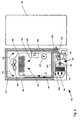
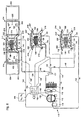
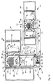
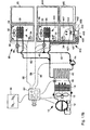
Fig. 17A is a schematic drawing illustrating a modular distributed refrigeration appliance system similar to the embodiment illustrated inFig. 12 incorporating another embodiment of a cascade cooling according to the invention. -
Fig. 17B is a schematic drawing illustrating a modular distributed refrigeration appliance system similar to the embodiment illustrated inFig. 12 incorporating another embodiment of a cascade cooling according to the invention. -
Fig. 18 is a partial schematic drawing illustrating refrigeration/storage modules that can be used in a modular distributed refrigeration system such as illustrated inFigs. 3 and6 . -
Fig. 19 is a partial schematic drawing illustrating another embodiment of refrigeration/storage modules that can be used in a modular distributed refrigeration system such as illustrated inFigs. 3 and6 . -
Fig. 20 is a partial schematic drawing illustrating another embodiment of refrigeration/storage modules that can be used in a modular distributed refrigeration system such as illustrated inFigs. 3 and6 . -
Fig. 21 is a schematic drawing illustrating another embodiment of a modular refrigeration system according to the invention. -
Fig. 22 is a schematic drawing illustrating another embodiment of a modular refrigeration system according to the invention. -
Fig. 23A is a schematic drawing illustrating another embodiment of refrigeration/storage modules that can be used in a distributed refrigeration system according to the invention. -
Fig. 23B is a schematic drawing illustrating another embodiment of refrigeration/storage modules that can be used in a distributed refrigeration system according to the invention. -
Fig. 24 is a schematic drawing illustrating another embodiment of a refrigeration/storage module that can be used in a distributed refrigeration system according to the invention. -
Fig. 25 is a schematic drawing illustrating another embodiment of a modular refrigeration system according to the invention. -
Fig. 26 is a schematic drawing illustrating another embodiment of a modular refrigeration system according to the invention. -
Figs. 27A - 27D are illustrations of temperature sequence cycles that can be provided in refrigeration/storage module according to the invention. -
Fig. 28 is a schematic drawing illustrating a distributed refrigeration system according to the invention installed in a schematic floor plan of a dwelling. -
Fig. 28A is an enlarged schematic drawing illustrating connection of a module to a supply and return system. -
Fig. 29 is a schematic drawing illustrating another embodiment of a distributed refrigeration system according to the invention installed in a schematic floor plan of a dwelling. -
Fig. 29A is an enlarged schematic drawing illustrating connection of a module to a single line system. - In a modular kitchen with multiple refrigeration modules the refrigeration system to cool the modules is a challenging problem. The simplest approach would be to have individual complete refrigeration systems for each module. In early phases of modularity for residential kitchens this might be the approach taken, especially when modular refrigeration product choices are few and economies of scale are not available. However, as modularity becomes more mainstream and kitchen designs begin to incorporate modular refrigeration products with appropriate infrastructure it will become desirable to have a single central cooling system from cost, manufacturing and energy efficiency perspectives. Consumers will be primarily interested in energy efficiency, cost, flexibility and expandability offered by a modular refrigeration appliance system with less concern about the central cooling technology to support the modular system.
- According to the invention, a modular refrigeration appliance system can be provided for a residential kitchen and other locations associated with a dwelling that can include a central cooling unit for some or all the refrigerating modules that a consumer may desire to include in their kitchen, either at the time of construction, or to expand or change refrigerating modules over time as needs or desires change. A modular kitchen could allow consumers to select multiple refrigeration modules fitting their lifestyles the best with ultimate flexibility in their kitchens and totally customizable kitchens with modular appliances not only for refrigeration but also for food preparation and kitchen clean-up. According to the invention a single, variable capacity central cooling unit can be provided that is capable of matching the cooling need to the aggregate heat load of the refrigerating modules. The central cooling unit can be arranged to run continuously by controlling the volume of cooling medium directed to each refrigerating module so that each module will be cooled to a user selected temperature and maintained at the desired temperature accurately. The cooling medium can be cold air, refrigerant or a liquid coolant such as an ethylene glycol and water solution. The central cooling unit can be a vapor compression system, but is not limited to that. If a central cooling unit is a vapor compression cooling system the central cooling unit can have a variable capacity compressor capable of handling the cooling load from multiple refrigerating module products. Refrigerating module products can include above freezing refrigerator modules, below freezing freezer modules, refrigerator freezer modules having above freezing and below freezing compartments in various configurations that can include, but are not limited to, built in, stackable, under counter or drawer configurations. Also, refrigerating module products could include specific purpose modules such as ice maker, wine cooler and bar refrigerator units. In addition, conventional refrigeration products having a complete refrigeration system can be combined with a modular refrigeration appliance system according to the invention. For example, one or more below freezing freezer units can be combined with a modular refrigeration system appliance arranged for a plurality of fresh food above freezing refrigerator modules. As will be described in more detail below, a hybrid approach can be an energy efficient approach to providing cooling for modular products since the central cooling unit can run under more favorable cooling cycle conditions since a very cold, i.e. below 0°F, cooling medium would not be required.
- Turning to
Fig. 1 , in one embodiment of the invention, illustrated in schematic form, refrigeratingmodules central cooling unit 10. In the embodiment illustrated inFig. 1 two refrigeratingmodules practice refrigerating modules unit 10 can be installed in a nearby location such as a basement, utility room, garage, outside, or, if desired, in the kitchen in the proximity of some or all of the refrigeration appliance modules depending on the style of dwelling and whether a basement or crawl space is available or desired for installation of thecentral cooling unit 10. Refrigeratingmodules modules S.N. 11/102,321 filed April 8, 2005 - Refrigerating
module 20 can have an insulatedcabinet 24 and aninsulated door 25 that can be hinged toinsulated cabinet 24 to selectively open and close anopening 28 ininsulated cabinet 24. Refrigeratingmodule 22 can have an insulatingcabinet 26 and aninsulated door 27 that can be hinged toinsulated cabinet 26 to selectively open and close anopening 29 ininsulated cabinet 26. Those skilled in the art will understand thatinsulated doors insulated doors modules heat exchanger 30 positioned in theinsulated cabinets modules heat exchanger fan 32 positioned to circulate air (illustrated by air flow arrows 38) over therespective heat exchangers 30 and through therespective refrigerating modules variable speed fan 32. Refrigeratingmodules temperature sensor 34 arranged to sense the temperature of the interior of refrigeratingmodules Temperature sensor 34 can be a thermister or other well known electronic or mechanical temperature sensing mechanism or device.Temperature selectors 36 can be provided for each of the refrigeratingmodules respective refrigerating modules temperature selectors 36 are illustrated schematically spaced from refrigeratingmodules temperature selectors 36 can be located in each of the refrigeratingmodules Temperature selectors 36 can comprise a well known mechanical or electronic selector mechanism to allow a user to select an operating temperature for therespective refrigerating modules - The refrigeration appliance system illustrated in schematic form in
Fig. 1 also includes acentral cooling unit 10. Central coolingunit 10 can include avariable speed compressor 12, acondenser 14, and anexpansion device 18 connected in a refrigerating circuit with a chilledliquid evaporator 40. A variablespeed condenser fan 16 can be provided to circulate air overcondenser 14. Chilledliquid evaporator 40 can be a shell and tube evaporator also known as a secondary loop evaporator.Expansion device 18 can be an expansion device with feedback arranged to control refrigerant flow throughexpansion device 18 based on the heat load in the refrigeration appliance system. Central coolingunit 10 can be connected to the refrigeratingmodules insulated conduits 42 forming a cooling medium circuit for conveying liquid coolant from chilledliquid evaporator 40 toheat exchangers 30 and fromheat exchangers 30 to chilledliquid evaporator 40. Liquid coolant, not shown, contained in chilledliquid evaporator 40,insulated conduits 42 andheat exchangers 30 can be circulated by apump 44 that can be a variable speed pump. Further, each refrigerating module can have avalve 46 to control flow of liquid coolant into theheat exchanger 30.Valves 46 can be on-off valves to allow or prevent flow of liquid coolant through theheat exchanger 30 for a refrigerating module. Those skilled in the art will appreciate that if a single speedheat exchanger fan 32 is used in arefrigerating module adjustable valve 46 can be used to control the amount of liquid coolant flowing into aheat exchanger 30, although it can be more energy efficient to use a variable speedheat exchanger fan 32, avariable speed pump 44 and an on-offvalve 46 to control the temperature in therespective refrigerating modules unit 10 can also have a microprocessor basedcontroller 50 having afirst portion 52 that can be arranged to control the operation ofcentral cooling unit 10 and asecond portion 54 arranged to control the volume of liquid coolant directed to therespective refrigerating modules control circuit 56 can be provided to connect thetemperature sensors 34, thetemperature selectors 36, thevariable speed compressor 12, the variablespeed condenser fan 16, theexpansion device 18, pump 44,valves 46 andheat exchanger fans 32 withcontroller 50. Thus, a refrigeration appliance system according to the invention is illustrated inFig. 1 as a distributed refrigeration system that can have a variable capacity vapor compression condensing unit and secondary loop utilizing a chilled liquid evaporator network. One example of a liquid coolant that can be used is DYNALENE HC heat transfer fluid, a water-based organic salt that is non-toxic, non-flammable with low viscosity, although those skilled in the art will understand that other liquid coolant solutions such as an ethylene glycol and water solution can be used as desired. - According to the invention,
central cooling unit 10 can be continuously operating so that chilled liquid at an adequate temperature to achieve the lowest selected temperature in the refrigeration appliance system is continuously circulated ininsulated conduits 42 forming a cooling medium circuit from chilledliquid evaporator 40 to refrigeratingmodules Controller 50 can be arranged to adjust the capacity of thecentral cooling unit 10 in response to the aggregate cooling load of the plurality of refrigeratingmodules modules Fig. 1 , according to the invention one or more than two refrigerating modules can be connected in the refrigerating appliance system. The aggregate cooling load can be determined by thefirst portion 52 ofcontroller 50 as a function of temperatures sensed bytemperature sensors 34, operating temperatures selected bytemperature selectors 36, and feedback fromexpansion device 18.Controller 50 can also be arranged to control the operating temperature in each of the refrigeratingmodules Second portion 54 ofcontroller 50 can be arranged to controlvalves 46 andheat exchanger fans 32 to maintain the selected operating temperatures in the respective refrigerating modules based on the settings oftemperature selectors 36 andtemperature sensors 34. Thus, according to the invention, a single continuously operating variable capacitycentral cooling unit 10 can be provided for a plurality of refrigeratingmodules central cooling unit 10 can be arranged for chilling a cooling medium. A cooling medium circuit,insulated conduits 42, can be provided connecting thecentral cooling unit 10 to supply a cooling medium from thecentral cooling unit 10 to the plurality of refrigeratingmodules valves 46, can be connected in the cooling medium circuit,insulated conduits 42, for controlling flow of cooling medium to each of the refrigeratingmodules controller 50 andcontrol circuit 56 can be provided to adjust the capacity of the variable capacitycentral cooling unit 10 in order to supply sufficient cooling medium to cool the plurality of refrigeratingmodules controller 50 andcontrol circuit 56 can be arranged to adjust the volume of cooling medium directed to respective ones of the refrigeratingmodules valves 46, to maintain the selected operating temperature in therespective refrigerating modules Controller 50 can control the speed ofvariable speed pump 44 to vary the volume of liquid cooling in the cooling medium circuit,insulated conduits 42, andcontroller 50 can control the speed of variable speedheat exchanger fans 32 to further control the operating temperature in therespective refrigerating modules - Turning to
Fig. 2 , in another embodiment of the invention, illustrated in schematic form, refrigeratingmodules central cooling unit 60. Similar to the embodiment illustrated inFig. 1 , two refrigeratingmodules modules module 70 can have an insulatedcabinet 74 and aninsulated door 75 that can be hinged toinsulated cabinet 74 to selectively open andclose opening 78 ininsulated cabinet 74. Refrigeratingmodule 72 can have an insulatingcabinet 76 and aninsulated door 77 that can be hinged toinsulated cabinet 76 to selectively open andclose opening 79 ininsulated cabinet 76. Those skilled in the art will understand thatinsulated doors insulated doors modules temperature sensor 84 arranged to sense the temperature of the interior of refrigeratingmodules Temperature sensor 84 can be a thermister or other well known electronic or mechanical temperature sensing mechanism or device.Temperature selectors 86 can be provided for each of the refrigeratingmodules respective refrigerating modules temperature selectors 86 are illustrated schematically spaced from refrigeratingmodules temperature selector 86 can be located in each of the refrigeratingmodules Temperature selectors 86 can comprise a well known mechanical or electronic selector mechanism to allow a user to select an operating temperature for therespective refrigerating modules - The refrigeration appliance system illustrated in schematic form in
Fig. 2 also includes acentral cooling unit 60. Central coolingunit 60 can include avariable speed compressor 62, acondenser 64 and anexpansion device 68 connected in a refrigerating circuit with anevaporator 90. A variablespeed condenser fan 66 can be provided to circulate air overcondenser 64.Evaporator 90 can be a tube and fin evaporator for cooling air that can be used as the cooling medium in the embodiment ofFig. 2 .Expansion device 68 can be an expansion device with feedback arranged to control flow through theexpansion device 68 based on the heat load in the refrigeration appliance system including the refrigeratingmodules unit 60 can be connected to the refrigeratingmodules insulated ducts 92 forming a cooling medium circuit for conveying chilled air fromevaporator 90 to refi-igerating modules evaporator fan 94 that can be a variable speed fan.Air inlets 93 can lead from theinsulated ducts 92 to therespective refrigerating modules air outlets 95 can lead from therespective refrigerating modules air ducts 92.Air inlets 93 andair outlets 95 form the apparatus for receiving the cooling medium, chilled air, in the refrigeratingmodules Air inlets 93 andair outlets 95 can be positioned with respect toinsulated cabinets respective refrigerating modules arrows 80 schematically illustrate the air flow in theinsulated cabinets module baffle 96 to control flow of chilled air throughair inlets 93 into therespective refrigerating modules respective refrigerating modules speed evaporator fan 94 can vary the flow of chilled air into therespective refrigerating modules respective refrigerating modules unit 60 can have a microprocessor basedcontroller 100 having afirst portion 102 that can be arranged to control the operation ofcentral cooling unit 60 and asecond portion 104 to control the volume of chilled air directed to therespective refrigerating modules controller 50 in the embodiment ofFig. 1 . Acontrol circuit 106 can be provided to connect thetemperature sensors 84, thetemperature selectors 86, thevariable speed compressor 62, the variablespeed condenser fan 66, theexpansion device 68,evaporator fan 94, and baffles 96 tocontroller 100. Thus, a refrigeration appliance system according to the invention is illustrated inFig. 2 as a distributed refrigeration system having a variable capacity vapor compression condensing unit and a chilled forced air cooling delivery network. - According to the invention,
central cooling unit 60 can be continuously operating so that chilled air is continuously circulated ininsulated ducts 92 forming a cooling medium circuit fromevaporator 90 to refrigeratingmodules evaporator 90.Controller 100 can be arranged to adjust the capacity of thecentral cooling unit 60 in response to the aggregate cooling load of the plurality of refrigeratingmodules modules Fig. 2 , according to the invention one or more than two refrigerating modules can be connected in the refrigerating appliance system. The aggregate cooling load can be determined by thefirst portion 102 ofcontroller 100 as a function of temperatures sensed bytemperature sensors 84, operating temperatures selected withtemperature selectors 86, and feedback fromexpansion device 68.Controller 100 can also be arranged to control the operating temperature in each of the refrigeratingmodules Second portion 104 ofcontroller 100 can be arranged to controlbaffles 96 andevaporator fan 94 to maintain the selected operating temperatures based on the settings oftemperature selectors 86 andtemperature sensors 84. Thus, according to the invention, a single continuously operating variable capacitycentral cooling unit 60 can be provided for a plurality of refrigeratingmodules central cooling unit 60 can be arranged for chilling a cooling medium. A cooling medium circuit,insulated ducts 92, can be provided connecting thecentral cooling unit 60 to supply the cooling medium from thecentral cooling unit 60 to the plurality of refrigeratingmodules modules air inlets 93 andair outlets 95. Acontroller 100 andcontrol circuit 106 can be provided to adjust the capacity of the variable capacitycentral cooling unit 60 in order to supply sufficient cooling medium to cool the plurality of refrigeratingmodules controller 100 andcontrol circuit 106 can be arranged to adjust the volume of cooling medium directed to respective ones of the refrigeratingmodules evaporator fan 94 and baffles 96, to maintain the selected operating temperature in therespective refrigerating modules Controller 100 can control the speed ofvariable speed fan 94 to vary the volume of cooling medium, chilled air, in the cooling medium circuit,insulated ducts 92, to further control the operating temperature in therespective refrigerating modules Fig. 2 is preferably used for above freezing refrigerator modules to avoid the need to circulate chilled air in the cooling medium circuit to achieve temperatures approximating 0°F for freezer modules, although freezer modules can be included in theFig. 2 embodiment if desired. - Turning to
Fig. 3 , in another embodiment of the invention, illustrated in schematic form, refrigeratingmodules central cooling unit 110. According to the invention one refrigerating module or more than three refrigerating modules can be provided in the refrigeration appliance system as desired. Refrigeratingmodules module 120 can have an insulatedcabinet 126 and aninsulated door 127 that can be hinged toinsulated cabinet 126 to selectively open and close anopening 135 ininsulated cabinet 126. Refrigeratingmodule 122 can have an insulatedcabinet 128 and aninsulated door 129 that can be hinged toinsulated cabinet 128 to selectively open and close anopening 137 ininsulated cabinet 128. Refrigeratingmodule 124 can have an insulatedcabinet 140 and aninsulated door 141 to selectively open and close anopening 139 ininsulated cabinet 140. Those skilled in the art will understand thatinsulated doors insulated doors modules refrigerating module evaporator 130 and a refrigerating module variablespeed evaporator fan 132 arranged to circulate chilled air in the respective refrigerating modules. Air flowarrows 148 schematically illustrate the chilled air flow in the respective refrigerating modules. Refrigeratingmodules temperature sensor 134 arranged to sense the temperature of the interior of refrigeratingmodules Temperature sensor 134 can be a thermister or other well known electronic or mechanical temperature sensing mechanism or device.Temperature selectors 136 can be provided for each of the refrigeratingmodules respective refrigerating modules temperature selectors 136 are illustrated schematically spaced from refrigeratingmodules temperature selector 136 can be located in each of the refrigeratingmodules Temperature selectors 136 can comprise a well known mechanical or electronic selector mechanism to allow a user to select an operating temperature for therespective refrigerating modules - The refrigeration appliance system illustrated in schematic form in
Fig. 3 also includes acentral cooling unit 110.Central cooling unit 110 can include avariable speed compressor 112, acondenser 114 and a variablespeed condenser fan 116.Central cooling unit 110 can also include a manifold 117 and anaccumulator 118.Central cooling unit 110 can be connected to the refrigeratingmodules supply conduits 142 and insulatedreturn conduits 144 forming a cooling medium circuit for conveying refrigerant fromcentral cooling unit 110 throughmanifold 117 to refrigeratingmodules modules accumulator 118 through insulatedreturn conduits 144 for delivery tovariable speed compressor 112. Refrigeratingmodule evaporators 130 form the apparatus for receiving the cooling medium, refrigerant, in the refrigeratingmodules module expansion device 138 to control flow of refrigerant into the respectiverefrigerating module evaporators 130.Expansion devices 138 can be an expansion device with feedback arranged to control refrigerant flow throughexpansion device 138.Central cooling unit 110 can also have a microprocessor basedcontroller 150 having afirst portion 152 that can be arranged to control the operation ofcentral cooling unit 110 and asecond portion 154 to control the volume of refrigerant directed to therespective refrigerating modules controller 50 in the embodiment ofFig. 1 . Acontrol circuit 156 can be provided to connect thetemperature sensors 134, thetemperature selectors 136, thevariable speed compressor 112, the variablespeed condenser fan 116,expansion devices 138 andevaporator fans 132 tocontroller 150. Thus, a refrigeration appliance system according to the invention is illustrated inFig. 3 as a distributed refrigeration system having a variable capacity vapor compression condensing unit and an evaporator network. Depending on the refrigerating modules selected, the modules can all be above freezing, all below freezing, or a mixture of above freezing and below freezing refrigerating modules. - According to the invention,
central cooling unit 110 can be continuously operating so that refrigerant is continuously circulated in refrigerant lines that can be insulatedsupply conduits 142 and insulatedreturn conduits 144 forming a cooling medium circuit fromcondenser 114 throughmanifold 117 to refrigeratingmodules compressor 112 throughaccumulator 118.Controller 150 can be arranged to adjust the capacity of thecentral cooling unit 110 in response to the aggregate cooling load of the plurality of refrigeratingmodules modules Fig. 3 , according to the invention one or more than three refrigerating modules can be connected in the refrigerating appliance system. The aggregate cooling load can be determined by thefirst portion 152 ofcontroller 150 as a function of temperatures sensed bytemperature sensors 134, operating temperatures selected withtemperature selectors 136 and feedback fromexpansion devices 138.Controller 150 can also be arranged to control the operating temperature in each of the refrigeratingmodules Second portion 154 ofcontroller 150 can be arranged to controlexpansion devices 138 and refrigeratingmodule evaporator fans 132 to maintain the selected operating temperatures based on the settings oftemperature selectors 136 andtemperature sensors 134.Controller 150 can be arranged to maintain approximately the same evaporator pressure in therefrigerating module evaporators 130 and control the temperature in the respective refrigerating modules by varying the flow of refrigerant into the refrigeratingmodule evaporators 130 and controlling the speed of the respective refrigeratingmodule evaporator fans 132. Thus, according to the invention, a single, continuously operating variable capacitycentral cooling unit 110 can be provided for a plurality of refrigeratingmodules central cooling unit 110 can be arranged for chilling a cooling medium, a refrigerant. A cooling medium circuit including refrigerant lines that can be insulated supply conduits and insulatedreturn conduits central cooling unit 110 to supply the cooling medium from thecentral cooling unit 110 to the plurality of refrigeratingmodules expansion devices 138, can be provided for controlling flow of cooling medium, refrigerant, to each of the refrigeratingmodules controller 150 andcontrol circuit 156 can be provided to adjust the capacity of the variable capacitycentral cooling unit 110 in order to supply sufficient cooling medium to cool the plurality of refrigeratingmodules controller 150 andcontrol circuit 156 can be arranged to adjust the volume of cooling medium, refrigerant, directed to respective ones of the refrigeratingmodules expansion devices 138 and refrigeratingmodule evaporator fans 132, to maintain the selected operating temperature in therespective refrigerating modules Controller 150 can control the speed ofvariable speed compressor 112, variablespeed condenser fan 116 andexpansion devices 138 to control the condensing and evaporating pressures of the cooling medium, refrigerant, in the cooling medium circuit including refrigerant lines that can be insulated supply and returnconduits respective refrigerating modules - Turning to
Fig. 4 , in another embodiment of the invention, illustrated in schematic form, refrigeratingmodules central cooling unit 110. According to the invention one refrigerating module or more than three refrigerating modules can be provided in the refrigeration appliance system as desired. As described in the embodiment disclosed inFig. 3 , refrigeratingmodules module 160 can be a refrigerator freezer having arefrigerator compartment 168 and afreezer compartment 166.Refrigerator compartment 168 can have an insulated refrigerator compartment door 174 hinged toinsulated cabinet 162 andfreezer compartment 166 can have an insulatedfreezer compartment door 172 hinged toinsulated cabinet 162. Those skilled in the art will understand thatinsulated doors insulated doors modules refrigerating module evaporator 130 and a variable speed refrigeratingmodule evaporator fan 132 arranged to circulate chilled air in the respective refrigerating modules, seeair flow arrows 148. Refrigeratingmodules temperature sensor 134 arranged to sense the temperature of the interior of refrigeratingmodules Refrigerator freezer module 160 can have atemperature sensor 134 forrefrigerator compartment 168 and atemperature sensor 134 forfreezer compartment 166.Temperature sensors 134 can be a thermister or other well known electronic or mechanical temperature sensing mechanism or device.Temperature selectors 136 can be provided for each of the refrigeratingmodules respective refrigerating modules Refrigerator freezer 160 can have twotemperature selectors 136, one for therefrigerator compartment 168 and one for thefreezer compartment 166. Whiletemperature selectors 136 are illustrated schematically spaced from refrigeratingmodules modules Temperature selectors 136 can comprise a well known mechanical or electronic selector mechanism to allow a user to select an operating temperature for therespective refrigerating modules - The refrigeration appliance system illustrated in schematic form in
Fig. 4 , similar to the embodiment illustrated inFig. 3 , can include acentral cooling unit 110.Central cooling unit 110 can include avariable speed compressor 112, acondenser 114 and a variablespeed condenser fan 116.Central cooling unit 110 can also include a manifold 117 and anaccumulator 118.Central cooling unit 110 can be connected to the refrigeratingmodules supply conduits 142 and insulatedreturn conduits 144 forming a cooling medium circuit for conveying refrigerant fromcentral cooling unit 110 throughmanifold 117 to refrigeratingmodules modules accumulator 118 through insulatedreturn conduits 144 for delivery tovariable speed compressor 112. Refrigeratingmodule evaporators 130 form the apparatus for receiving the cooling medium, refrigerant, in the refrigeratingmodules module expansion device 138 to control flow of refrigerant into the respectiverefrigerating module evaporators 130.Expansion devices 138 can be an expansion device with feedback arranged to control refrigerant flow throughexpansion device 138.Central cooling unit 110 can also have a microprocessor basedcontroller 150 having afirst portion 152 that can be arranged to control the operation ofcentral cooling unit 110 and asecond portion 154 to control the volume of refrigerant directed to therespective refrigerating modules controller 50 in the embodiment ofFig. 1 . Acontrol circuit 156 can be provided to connect thetemperature sensors 134, thetemperature selectors 136, thevariable speed compressor 112, the variablespeed condenser fan 116,expansion devices 138 andevaporator fans 132 tocontroller 150. Thus, a refrigeration appliance system according to the invention is illustrated inFig. 4 as a distributed refrigeration system having a variable capacity vapor compression condensing unit and an evaporator network. Depending on the refrigerating modules selected, the modules can all be above freezing, all below freezing, or a mixture of above freezing and below freezing refrigerating modules in addition torefrigerator freezer module 160. - Refrigerating
module 160 can be a two temperature refrigerator freezer module that can be arranged to have an above freezingrefrigerator compartment 168 and a below freezingfreezer compartment 166 as noted above. Aninsulated compartment separator 164 can be provided to divideinsulated cabinet 162 into arefrigerator compartment 168 and afreezer compartment 166.Freezer compartment 166 can have an evaporator compartment that can be formed by anevaporator compartment wall 170 that can be arranged to separate therefrigerating module evaporator 130 from thefreezer compartment 166.Evaporator compartment wall 170 is illustrated schematically as a dashed line below refrigeratingmodule evaporator 130 to indicate that air flows (air flow arrows 148) intofreezer compartment 166 from the refrigeratingmodule evaporator 130, and similarly, air returns to the evaporator compartment under the influence of refrigeratingmodule evaporator fan 132.Insulated compartment separator 164 can have chilledair passages 176 positioned oncompartment separator 164 that can allow chilled air (air flow arrows 158) from thefreezer compartment 166 or evaporator compartment to flow intorefrigerator compartment 168 as is well known in the art.Compartment separator 164 can have arefrigerator compartment damper 178 to control the flow of air from therefrigerator compartment 168 back tofreezer compartment 166 and refrigeratingmodule evaporator 130 drawn by refrigeratingmodule evaporator fan 132. In the embodiment of the invention illustrated inFig. 4 ,refrigerator compartment damper 178 is shown in the return air path fromrefrigerator compartment 168. Those skilled in the art will understand thatchilled air passages 176 could be arranged in the return air path fromrefrigerator compartment 168 andrefrigerant compartment damper 178 arranged in the flow of chilled air intorefrigerator compartment 168 if desired.Refrigerator compartment damper 178 can be an automatic damper operated bycontroller 150 as illustrated inFig. 4 , or, if desired,refrigerator compartment damper 178 can be a manually adjustable damper manually adjusted by the user andtemperature sensor 134 andtemperature selector 136 eliminated fromfreezer compartment 166. - Similar to the embodiment of
Fig. 3 , according to the invention,central cooling unit 110 can be continuously operating so that refrigerant is continuously circulated in refrigerant lines that can be insulatedsupply conduits 142 and returnconduits 144 forming a cooling medium circuit fromcondenser 114 throughmanifold 117 to refrigeratingmodules compressor 112 throughaccumulator 118.Controller 150 can be arranged to adjust the capacity of thecentral cooling unit 110 in response to the aggregate cooling load of the plurality of refrigeratingmodules modules Fig. 4 , according to the invention one or more than three refrigerating modules can be connected in the refrigerating appliance system. The aggregate cooling load can be determined by thefirst portion 152 ofcontroller 150 as a function of temperatures sensed bytemperature sensors 134, operating temperatures selected withtemperature selectors 136, and feedback fromexpansion devices 138.Controller 150 can also be arranged to control the operating temperature in each of the refrigeratingmodules Second portion 154 ofcontroller 150 can be arranged to controlexpansion devices 138 and refrigeratingmodule evaporator fans 132 to maintain the selected operating temperatures based on the settings oftemperature selectors 136 andtemperature sensors 134. In addition,second portion 154 ofcontroller 150 can be arranged to controlrefrigerator compartment damper 178 to control the amount of chilled air flowing fromfreezer compartment 166 and refrigeratingmodule evaporator 132 throughcompartment separator 164 intorefrigerator compartment 168 in conjunction with refrigeratingmodule evaporator fan 132 to maintain the user selected temperature inrefrigerator compartment 168 as well as infreezer compartment 166.Controller 150 can be arranged to maintain approximately the same evaporator pressure in therefrigerating module evaporators 130 and control the temperature in therespective refrigerating modules module evaporators 130 and controlling the speed of the respective refrigeratingmodule evaporator fans 132. Thus, according to the invention, a single, continuously operating variable capacitycentral cooling unit 110 can be provided for a plurality of refrigeratingmodules module 160 can be set to have a refrigerator compartment and a freezer compartment. The variable capacitycentral cooling unit 110 can be arranged for chilling a cooling medium, a refrigerant. A cooling medium circuit that can include refrigerant lines that can be insulated supply conduits and insulatedreturn conduits central cooling unit 110 to supply the cooling medium from thecentral cooling unit 110 to the plurality of refrigeratingmodules expansion devices 138, can be provided for controlling flow of cooling medium, refrigerant, to each of the refrigeratingmodules controller 150 andcontrol circuit 156 can be provided to adjust the capacity of the variable capacitycentral cooling unit 110 in order to supply sufficient cooling medium to cool the plurality of refrigeratingmodules controller 150 andcontrol circuit 156 can be arranged adjust the volume of cooling medium, refrigerant, directed to respective ones of the refrigeratingmodules expansion devices 138 and refrigeratingmodule evaporator fans 132, to maintain the selected operating temperature in therespective refrigerating modules Controller 150 can control the speed ofvariable speed compressor 112, variablespeed condenser fan 116 andexpansion devices 138 to control the condensing and evaporating pressures of the cooling medium, refrigerant, in the cooling medium circuit including refrigerant lines that can be insulated supply and returnconduits respective refrigerating modules - Turning to
Fig. 5 , afreezer module 180 is illustrated that can be used in combination with a refrigeration appliance system according to the invention.Freezer module 180 can be a conventional freezer capable of operating without connection to the refrigeration appliance system according to the invention. Particularly when a freezer module arranged for 0°F storage temperatures is desired for use in combination with the embodiments illustrated inFig. 1 (employing liquid coolant as the cooling medium),Fig. 2 (employing chilled air as the cooling medium), orFig. 3 (particularly when above freezing refrigerator modules will be connected in the refrigeration appliance system) it can be advantageous to incorporate afreezer module 180 as illustrated inFig. 5 . However, afreezer module 180 can be combined with any of the embodiments according to the invention.Freezer module 180 can have a insulatedfreezer cabinet 182 defining anopening 184 for access to the freezer compartment and can have an insulatedfreezer door 185 hinged to theinsulated freezer cabinet 182 to selectively open and close the freezer compartment.Freezer door 185 can have a handle, not shown, to facilitate opening and closingfreezer door 185 for access tofreezer module 180.Freezer module 180 can include afreezer cooling unit 189 in amachinery compartment 186 outside the refrigerated portion of thefreezer cabinet 182 that can include afreezer compressor 190, afreezer condenser 192 and afreezer condenser fan 194.Freezer module 180 can include afreezer evaporator 196 that can be positioned ininsulated freezer cabinet 182 and can have afreezer evaporator fan 198 and afreezer expansion device 204.Freezer module 180 can have afreezer temperature sensor 200 that can be similar to the temperature sensors described above.Freezer module 180 can also have afreezer temperature selector 202 to allow user to select the operating temperature for the freezer module.Freezer module 180 can have acontroller 208 and acontrol circuit 206 connecting thefreezer temperature sensor 200,freezer temperature selector 202,freezer compressor 190,freezer condenser fan 194 andfreezer evaporator fan 198 tocontroller 208.Controller 208 can operatefreezer module 180 in a manner similar to conventional freezer products as is well known in the art. Those skilled in the art will understand thatfreezer compressor 190,freezer condenser fan 194 andfreezer evaporator fan 198 can be provided with variable speed motors as desired for optimum operation.Freezer expansion device 204 can be an expansion device with feedback as used in the embodiments ofFigs. 1-4 or can be a capillary tube expansion device, again as well known in the art.Freezer compressor 190 can be a variable speed compressor if desired as is well known in the art. Alternately, those skilled in the art will understand thatfreezer condenser 192 and/orfreezer evaporator 196 can be static heat exchangers and that if a static heat exchanger is used the respectivefreezer condenser fan 194 and/orfreezer evaporator fan 198 could be eliminated. Forexample freezer module 180 could be a chest freezer havingfreezer evaporator 196 positioned in contact with theinner liner 210 defining the freezer compartment in the insulation between theinner liner 210 andcabinet 182 as is well known in the art. Similarly,freezer condenser 192 could be positioned in contact withcabinet 182 positioned in the insulation betweeninner liner 210 andcabinet 182 as is well known in the art. - Turning to schematic
Fig. 6 , in another embodiment of the invention, a plurality ofsatellite stations refrigeration appliance modules 214 located in proximity of the satellite station to form a distributed refrigeration appliance system. Refrigeration appliance modules can be free standing or built in modules and can be general purpose refrigerator, freezer or special purpose modules.Satellite stations 212 andrefrigeration appliance modules 214 can be located in a residential kitchen or other locations associated with a dwelling as desired. The central cooling unit can be similar to the central cooling unit illustrated inFig. 3 , and accordingly, will use the same reference numerals as thecentral cooling unit 110 illustrated inFig. 3 .Central cooling unit 110,controller 150 and the central cooling system operation are described in detail above in connection with the embodiment ofFig. 3 . As noted above,central cooling unit 110 can be located in a location remote from a residential kitchen if desired. - According to the invention one satellite station or more than three satellite stations can be provided in the refrigeration appliance system as desired.
Refrigeration appliance modules 214 can be located in proximity ofsatellite station 212 and can be connected tosatellite station 212 by aninsulated supply duct 216 and aninsulated return duct 218 for supplying chilled air to therefrigeration appliance modules 214 fromsatellite station 212. Whileinsulated supply duct 216 and insulatedreturn duct 218 are schematically illustrated as separate ducts, those skilled in the art will understand that the insulated ducts can be coaxial or, alternately, formed insulated ducts with two discrete parallel passages if desired. Those skilled in the art will understand that if only onerefrigeration appliance module 214 will be located in proximity of asatellite station 212 that only one set of insulated supply and return ducts can be provided, or alternately, the unused set of ducts can be plugged or blocked to provide for future expansion of the system.Satellite station 212 can include asatellite station evaporator 219 that can be connected tocentral cooling system 110 through a refrigerant line that can be an insulatedsupply conduit 142 throughexpansion device 138 and a refrigerant line that can be an insulatedreturn conduit 144. As is well known in the art,quick connect fittings 145 can be used to connectsatellite station 212 to the refrigerant lines.Expansion device 138 can be an adjustable expansion device with feedback based on the load experienced by thesatellite station 212, and can be connected tocontroller 150 throughcontrol circuit 156. Those skilled in the art will understand that, if desired, one ormore satellite stations 212 can include a plurality of expansion devices, not shown, connected in a refrigeration circuit for thesatellite station 212 to operate the satellite station evaporator at a plurality of operating temperatures to, for example, allow a user to selectively operate one or more of therefrigeration appliance modules 214 connected to asatellite station 212 to be operated as an above freezing refrigerator compartment or as a below freezing freezer compartment by merely selecting a different expansion device to control thesatellite station evaporator 219. For example, plural expansion devices could be connected in parallel in the refrigeration circuit including thesatellite station evaporator 219. A multi-temperature evaporator system is disclosed inU.S. Patent No. 5,377,498 , assigned to the assignee of this application.U.S. 5,377,498 is incorporated herein by reference.Satellite station 212 can also have a variable speed satellite station evaporatorfan 220 that can be connected tocontroller 150 throughcontrol circuit 156. Those skilled in the art will understand that satellite station evaporatorfan 220 can be a single speed fan if desired.Satellite station 212 can also have atemperature sensor 134 arranged to sense the temperature insatellite station 212.Satellite stations 212' and 212" can be similar tosatellite station 212. Whilesatellite stations 212' and 212" are illustrated withoutrefrigeration appliance modules 214 positioned in proximity to the respective satellite stations to simplify the drawings, those skilled in the art will understand that refrigeration appliance modules such asmodules 214 illustrated in proximity ofsatellite station 212 can, and in practiceadditional satellite stations 212' and 212", if included in the distributed refrigeration appliance system, would likely be combined with one or morerefrigeration appliance modules 214. -
Refrigeration appliance module 214 can have an insulatedcabinet 223 and at least oneinsulated door 224 that can be hinged toinsulated cabinet 223 to selectively open and close anopening 225 ininsulated cabinet 223. Those skilled in the art will understand thatinsulated doors 224 can be provided with a suitable handle, not shown, to facilitate opening and closinginsulated doors 224.Refrigeration appliance module 214 can have anadjustable baffle 222 that can be positioned to control air flow through insulatedsupply duct 216.Adjustable baffle 222 can be variably movable between open and closed positions to permit, block and vary the flow of chilled air intorefrigeration appliance module 214.Adjustable baffle 222 can be manually adjustable by a user to control the temperature inrefrigeration appliance module 214, or, as illustrated, can be an automatic adjustable baffle connected tocontroller 150 throughcontrol circuit 156. Air flowarrows 227 schematically illustrate chilled air flow fromsatellite station 212 torefrigeration appliance module 214 through insulatedsupply duct 216 and back tosatellite station 212 through insulatedreturn duct 218. Those skilled in the art will understand thatadjustable baffle 222 can be positioned in insulatedreturn duct 218, or if desired anadjustable baffle 222 can be provided in both supply and return ducts in order to isolate arefrigeration appliance module 214.Refrigeration appliance module 214 can also have atemperature sensor 134 to sense the temperature withininsulated cabinet 223. As above,temperature sensors 134 can be a thermister or other well known electronic or mechanical temperature sensing mechanism or device and can be connected tocontroller 150 throughcontrol circuit 156. Atemperature selector 136 can be provided for each of therefrigeration appliance modules 214 to allow the user to select the operating temperature for each of therefrigeration appliance modules 214. Whiletemperature selectors 136 are illustrated schematically spaced from refrigeration appliance modules 214 atemperature selector 136 can be located in each of therefrigeration appliance modules 214 as is well known in the art, or can be centrally located in a combined user interface as illustrated if desired.Temperature selectors 136 can comprise a well known mechanical or electronic selector mechanism to allow a user to select an operating temperature for the respectiverefrigerating appliance module 214 and can be connected tocontroller 150 throughcontrol circuit 156. As above, the aggregate distributed refrigeration appliance system cooling load can be determined by thefirst portion 152 ofcontroller 150 as a function of temperatures sensed bytemperature sensors 134, operating temperatures selected withtemperature selectors 136 and feedback based on load fromexpansion devices 138.Controller 150 can also be arranged to control the operating temperature in each of therefrigeration appliance modules 214.Second portion 154 ofcontroller 150 can be arranged to controlexpansion devices 138,adjustable baffles 222 and satellite station evaporatorfans 220 to maintain the selected operating temperatures based on the settings oftemperature selectors 136 andtemperature sensors 134.Controller 150 can be arranged to maintain approximately the same evaporator pressure in thesatellite station evaporators 219 and control the temperature in the respectiverefrigeration appliance modules 214 by varying the flow of refrigerant into thesatellite station evaporators 219, the position ofautomatic baffles 222 and controlling the speed of the respective refrigeration appliancemodule evaporator fans 220.Refrigeration appliance modules 214 connected to asatellite station 212 can be operated at different operating temperatures. For instance, onerefrigeration appliance module 214 can be set to operate as an above freezing refrigerator module and anotherrefrigeration appliance module 214 connected to thesame satellite station 212 can be set to operate as a below freezing freezer module if so desired. If manual baffles are provided instead of automatic baffles those skilled in the art will understand that the user can set the baffles to obtain the desired temperature in the refrigeration appliance modules. Thus, according to the invention, a single, continuously operating variable capacitycentral cooling unit 110 can be provided for a plurality ofrefrigeration appliance modules 214 that can be set to operate at different operating temperatures that can include temperatures to allow operation of a refrigeration appliance module as an above freezing refrigerator compartment, a below freezing freezer compartment or another refrigeration appliance such as an ice maker. - Turning to schematic
Figs. 7A, 7B and 7C , in another embodiment of the invention, a two compartment refrigeration appliance modules can be combined with a satellite station. Asingle satellite station 212 can be connected to refrigeration appliance modules is shown in each ofFigs. 7A and 7B with thecentral cooling unit 110 omitted to simplify the drawings. Arefrigeration appliance module 228 can be used in a distributed refrigeration appliance system having one or morerefrigeration appliance modules 214 located in proximity of one ormore satellite stations 212 to form a distributed refrigeration appliance system.Refrigeration appliance module 228 can be a free standing or a built in module and can be general purpose refrigerator, freezer or a special purpose module.Refrigeration appliance module 228 can be located in a residential kitchen or other locations associated with a dwelling as desired. The central cooling unit, not shown, can be similar to the central cooling unit illustrated inFig. 3 , and as above, can be located remote from the residential kitchen.Central cooling unit 110,controller 150 and the central cooling system operation are described in detail above in connection with the embodiment ofFig. 3 andFig. 6 . Those skilled in the art will understand that more than onesatellite station 212 can be provided and thatsatellite station 212 can be connected tocentral cooling unit 110 through well knownquick connect fittings 145 to refrigerant lines that can be insulatedsupply conduits controller 150 throughcontrol circuit 156 as illustrated inFig. 6 . In the embodiment illustrated inFig. 7A a two compartmentrefrigeration appliance module 228 can be connected tosatellite station 212 by aninsulated supply duct 232 and aninsulated return duct 234. Arefrigeration appliance module 214 can also be connected tosatellite station 212 as in the embodiment illustrated inFig. 6 .Refrigeration appliance module 214 is described in detail above and accordingly will not be described in detail again in connection withFigs. 7A - 7C . Refrigeratingmodule 214 will use the same reference numerals as refrigeratingmodule 214 inFig. 6 .Refrigeration appliance module 228 can have an insulatedcabinet 229 that can have two insulateddoors 230 hinged toinsulated cabinet 229 to selectively open andclose openings 233.Insulated doors 230 can be provided with a handle, not shown, to facilitate opening and closinginsulated doors 230.Insulated cabinet 229 can have an insulatedcompartment separator 231 to divideinsulated cabinet 229 into twocompartments insulated doors 230.Insulated supply duct 232 can be arranged to extend substantially throughcompartment 238 to supply chilled air tocompartment 237.Insulated supply duct 232 can have an opening 232' incompartment 238 to supply chilled air tocompartment 238. Opening 232' can be locatedadjacent compartment separator 231 and can be provided with anadjustable baffle 235 that can be arranged to control chilled air flow intocompartments insulated return duct 234 can extend substantially throughcompartment 238 to provide for chilled air return fromcompartment 237 without flowing throughcompartment 238. Insulatedreturn duct 234 can have an opening 234' that can be locatedadjacent compartment separator 231 and can be provided with anadjustable baffle 235 that can be arranged to control chilled air flow out ofcompartments refrigerated appliance module 214,insulated supply duct 232 can be provided with anadjustable baffle 222 to control the quantity of chilled air supplied torefrigeration appliance module 228 fromsatellite station 212 by satellite station evaporatorfan 220.Adjustable baffles compartments controller 150 throughcontrol circuit 156 as generally described above. Refrigeratingmodule 214 can operate in the same manner asrefrigeration appliance modules 214 as described in connection withFig. 6 . Thus, a user can operaterefrigeration appliance module 214 at one operating temperature and can operate the twocompartments refrigeration appliance module 228 at different temperatures and a different temperatures fromrefrigeration appliance module 214 as desired. As described above,compartment refrigeration appliance module 214. Those skilled in the art will understand that alternate insulated duct and damper arrangements can be provided to provide chilled air flow intocompartments - In the embodiment illustrated in
Fig. 7B and 7C a two compartmentrefrigeration appliance module 228 can be connected tosatellite station 212 by aninsulated supply duct 216 and aninsulated return duct 218. Arefrigeration appliance module 214 can be connected tosatellite station 212 as in the embodiment illustrated inFig. 6 .Refrigeration appliance module 228 can have an insulatedcabinet 229 that can have two insulateddoors 230 hinged toinsulated cabinet 229 to selectively open andclose openings 233.Insulated doors 230 can be provided with a handle, not shown, to facilitate opening and closinginsulated doors 230.Insulated cabinet 229 can have an insulated compartment separator 231' to divideinsulated cabinet 229 into twocompartments insulated doors 230. Insulated compartment separator 231' can have acirculation fan 236 provided in an opening in compartment separator 231' and can have asecond opening 239.Circulation fan 236 can be seen inFig. 7C . In the embodiment ofFig. 7B and 7C circulation fan 236 can control flow of chilled air fromcompartment 238 tocompartment 237. As described above,adjustable baffle 222 can control the flow of chilled air fromsatellite station 212 torefrigeration appliance module 228. Thus, for two compartment refrigeration appliance modules two embodiments have been illustrated for controlling the temperature in the twocompartments Fig. 7A , employs adjustable baffles to control the flow of chilled air to the respective compartments. Another approach, as shown inFig. 7B and 7C , employs acirculation fan 236 in compartment separator 231' to control flow of chilled air fromcompartment 238 intocompartment 237. Those skilled in the art will recognize that in theFig. 7B and 7C embodiment compartment 237 can only operate at a higher temperature thancompartment 238, whereas in theFig. 7A embodiment it can be possible to operatecompartment 237 at a lower temperature thancompartment 238. - Turning to schematic
Fig. 8A , in another embodiment of the invention, a satellite station can be combined with a refrigeration appliance module. InFig. 8A a combined satellite station /refrigeration appliance module 240 andrefrigeration appliance module 214 are illustrated without acentral cooling unit 110 oradditional satellite stations 212 andrefrigeration appliance modules 214 to simplify the drawings. A combined satellite station /refrigeration appliance module 240 can be used in a distributed refrigeration appliance system having one or morerefrigeration appliance modules more satellite stations 212 to form a distributed refrigeration appliance system. Combined satellite station /refrigeration appliance module 240 andrefrigeration appliance module 214 can be free standing or built in modules and can be general purpose refrigerator, freezer or special purpose modules. Combined satellite station /refrigeration appliance module 240 can be located in a residential kitchen or other locations associated with a dwelling as desired. Combined satellite station / refrigeration appliance module can have an insulatedcabinet 241, aninsulated door 242 that can be hinged toinsulated cabinet 241 for selective access to the interior of the insulated cabinet throughopening 243. Insulateddoor 242 can have a handle, not shown, to facilitate access to the combined satellite station /refrigeration appliance module 240. The central cooling unit, not shown, can be similar to the central cooling unit illustrated inFig. 3 .Central cooling unit 110,controller 150 and the central cooling system operation are described in detail above in connection with the embodiment ofFig. 3 . Those skilled in the art will understand that more than onesatellite station 212 can be provided and that one or more combined satellite station /refrigeration appliance modules 240 can be connected tocentral cooling unit 110 throughquick connect fittings 145 to refrigerant lines that can be insulatedsupply conduits controller 150 throughcontrol circuit 156 as illustrated inFig. 6 . - Combined satellite station /
refrigeration appliance module 240 can have asatellite station evaporator 246, a variablespeed evaporator fan 248 and anexpansion device 138.Satellite station evaporator 246 andexpansion device 138 can be connected to refrigerant lines that can be insulatedsupply conduit 142 and insulatedreturn conduit 144 throughquick connect fittings 145.Satellite evaporator 246 can be positioned in an evaporator compartment schematically indicated by dashedline 250.Refrigeration appliance module 214 can be located in proximity to combined satellite station /refrigeration appliance module 240 and can be connected to combined satellite station /refrigeration appliance module 240 by aninsulated supply duct 216 and aninsulated return duct 218.Refrigeration appliance module 214 is described above in detail and accordingly will not be described again in detail in connection withFig. 8A .Refrigeration appliance module 214 can operate in the same manner asrefrigeration appliance modules 214 as described in connection withFig. 6 . - Turning to schematic
Fig. 8B , in another embodiment of the invention, a combined satellite station /refrigeration appliance module 252 can be combined with arefrigeration appliance module 244 similar to the combination described above with respect toFig. 8A . Similar to the embodiment ofFig. 8A , a combined satellite station /refrigeration appliance module 252 can be used in a distributed refrigeration system having acentral cooling unit 110,controller 150 andcontrol circuit 156 as illustrated inFig. 3 havingplural satellite stations 212 andrefrigeration appliance modules central cooling unit 110,additional satellite stations 212 and refrigeration appliance modules have not been included inFig. 8B to simplify the drawings. Combined satellite station /refrigeration appliance module 252 andrefrigeration appliance module 244 can be free standing or built in modules and can be general purpose refrigerator, freezer or special purpose modules. Combined satellite station /refrigeration appliance module 252 can be located in a residential kitchen or other locations associated with a dwelling as desired. Combined satellite station /refrigeration appliance module 252 can have an insulatedcabinet 253, aninsulated door 254 that can be hinged toinsulated cabinet 253 for selective access to the interior of the insulated cabinet throughopening 255. Insulateddoor 254 can have a handle, not shown, to facilitate access to the combined satellite station /refrigeration appliance module 252. The central cooling unit, not shown, can be similar to the central cooling unit illustrated inFig. 3 . Operation ofcentral cooling unit 110 andcontroller 150 are described in detail above in connection with the embodiment ofFig. 3 . Those skilled in the art will understand that more than onesatellite station 212 can be provided and that one or more combined satellite station /refrigeration appliance modules 252 can be connected tocentral cooling unit 110 throughquick connect fittings 145 to refrigerant lines that can be insulatedsupply conduits controller 150 throughcontrol circuit 156 as illustrated inFig. 6 . - Combined satellite station /
refrigeration appliance module 252 can have a direct coolingsatellite station evaporator 256 and anexpansion device 138.Satellite station evaporator 256 andexpansion device 138 can be connected throughquick connect fittings 145 to refrigerant lines that can be insulatedsupply conduit 142 and insulatedreturn conduit 144 and tocontroller 150 throughcontrol circuit 156.Satellite evaporator 256 can be positioned in an evaporator compartment schematically indicated by dashed line 258.Refrigeration appliance module 244 can be located in proximity to combined satellite station /refrigeration appliance module 252 and can be connected to combined satellite station /refrigeration appliance module 252 by aninsulated supply duct 216 and aninsulated return duct 218.Refrigeration appliance module 244 can have an insulatedcabinet 262 that can have an insulateddoor 263 hinged toinsulated cabinet 262 to selectively provide access toinsulated cabinet 262 throughopening 264.Refrigeration appliance module 244 can have acirculation fan 260 that can circulate and control the volume of chilled air flowing intorefrigeration appliance module 244 from combined satellite station /refrigeration appliance module 252. Combined satellite station /refrigeration appliance module 252 andrefrigeration appliance module 244 can have atemperature sensor 134 as described above, and can have atemperature selector 136, not shown, that can be combined with the respective cabinets or can be part of a central user interface as described above and can be connected tocontroller 150 to control the temperatures in the refrigerated compartments.Refrigeration appliance module 244 can otherwise operate in the same manner asrefrigeration appliance modules 214 as described in connection withFig. 6 . - Turning to schematic
Fig. 9 , another embodiment of the invention, a satellite station can be combined with a two compartment refrigeration appliance module. InFig. 9 a two compartment combined satellite station /refrigeration appliance module 266 and arefrigeration appliance module 214 are illustrated without acentral cooling unit 110 orcontroller 150 andcontrol circuit 156 to simplify the drawings. A combined satellite station /refrigeration appliance module 266 can be used in a distributed refrigeration appliance system having one or morerefrigeration appliance modules more satellite stations refrigeration appliance module 266 andrefrigeration appliance module 214 can be free standing or built in modules and can be general purpose refrigerator, freezer or special purpose modules. Combined satellite station /refrigeration appliance module 266 can be located in a residential kitchen or other locations associated with a dwelling as desired. Combined satellite station / refrigeration appliance module can have an insulatedcabinet 268, aninsulated door 270 that can be hinged toinsulated cabinet 268 for selective access to the interior of the insulated cabinet throughopening 269. Insulateddoor 270 can have a handle, not shown, to facilitate access to the combined satellite station /refrigeration appliance module 266. The central cooling unit, not shown, can be similar to the central cooling unit illustrated inFig. 3 . Operation ofcentral cooling unit 110 andcontroller 150 are described in detail above in connection with the embodiment ofFig. 3 . Those skilled in the art will understand that more than onesatellite station refrigeration appliance modules 266 can be connected tocentral cooling unit 110 throughquick connect fittings 145 to refrigerant lines that can be insulatedsupply conduits controller 150control circuit 156 as illustrated inFig. 6 . - Combined satellite station /
refrigeration appliance module 266 can have asatellite station evaporator 272, a variablespeed evaporator fan 274 and anexpansion device 138.Satellite station evaporator 272 andexpansion device 138 can be connected to refrigerant lines that can be insulatedsupply conduit 142 and insulatedreturn conduit 144.Satellite evaporator 272 can be positioned in an evaporator compartment schematically indicated by dashedline 275. Combined satellite station /refrigeration appliance module 266 can have acompartment separator 276 that can be arranged to separateinsulated cabinet 268 into twocompartments Compartment 277 can include theevaporator compartment 275, and if a below freezing freezer compartment is desired,compartment 277 can be a freezer compartment since theevaporator compartment 275 is positioned incompartment 277.Passages 278 can allow air flow, indicated byair flow arrows 227, fromcompartment 277 and/orevaporator compartment 275 intocompartment 279 and to return toevaporator compartment 275 whenevaporator fan 274 is operated.Evaporator fan 274 can be a variable speed fan, or if desired, can be a single speed fan. Anadjustable baffle 280 can be provided in combination with one of thepassages 278 to control the air flow intocompartment 279.Adjustable baffle 278 can be connected to controlcircuit 156 and can be operated by controller 150 (seeFig. 3 ), or can be manually adjustable by the user to control the temperature incompartment 279 in combination withexpansion device 138 andsatellite evaporator fan 274. -
Refrigeration appliance module 214 can be located in proximity to combined satellite station /refrigeration appliance module 266 and can be connected to combined satellite station /refrigeration appliance module 266 by aninsulated supply duct 216 and aninsulated return duct 218. Refrigeration appliance module is described above in detail and accordingly will not be described in detail again in connection withFig. 9 . Combined satellite station /refrigeration appliance module 266 andrefrigeration appliance module 214 can have atemperature sensor 134 as described above, and can have atemperature selector 136, not shown, that can be combined with the respective cabinets or can be part of a central user interface as described above.Refrigeration appliance module 214 can operate in the same manner asrefrigeration appliance modules 214 as described in connection withFig. 6 . - Turning to schematic
Fig. 10 , in another embodiment of the invention, a satellite station can be combined with a refrigeration appliance module and a central cooling unit. InFig. 10 a combined satellite station / refrigeration appliance module /central cooling unit 282, asatellite station 212 and threerefrigeration appliance modules 214 are illustrated. A combined satellite station / refrigeration appliance module /central cooling station 282 can have more than onesatellite station 212 andrefrigeration appliance modules satellite stations 212 to form a distributed refrigeration appliance system. Combined satellite station / refrigeration appliance module /central cooling unit 282 andrefrigeration appliance modules 214 can be free standing or built in modules and can be general purpose refrigerator, freezer or special purpose modules. Combined satellite station / refrigeration appliance module /central cooling unit 282 can be located in a residential kitchen or other locations associated with a dwelling as desired. Combined satellite station / refrigeration appliance module /central cooling unit 282 can have an insulatedcabinet 312, aninsulated door 314 that can be hinged toinsulated cabinet 312 for selective access to the interior of the insulated cabinet throughopening 313. Whileinsulated door 314 is illustrated as a single door, those skilled in the art will understand that two doors can be provided, one for each of thecompartments door 314 can have a handle, not shown, to facilitate access to the combined satellite station /refrigeration appliance module 282.Insulated cabinet 312 can have acompartment separator 316 that can divideinsulated cabinet 312 into twocompartments - Combined satellite station / refrigeration appliance module /
central cooling unit 282 can have asatellite station evaporator 320, a variablespeed evaporator fan 322 and anexpansion device 138.Satellite station evaporator 322 andexpansion device 138 can be connected tomanifold 292 andaccumulator 294 to form a refrigerant circuit.Satellite evaporator 320 can be positioned in an evaporator compartment schematically indicated by dashedline 324.Refrigeration appliance module 214 is described above in detail. Combined satellite station / refrigeration appliance module /central cooling unit 282 andrefrigeration appliance module 214 can have atemperature sensors 134 as described above, and can have atemperature selector 136 that can be combined with the respective cabinets or can be part of a central user interface as described above.Refrigeration appliance module 214 can operate in the same manner asrefrigeration appliance modules 214 as described in connection withFig. 6 .Compartment separator 316 can havepassages 317 that can provide for air flow betweencompartment passages 317 can have anadjustable baffle 318 that can control the quantity of chilled air flowing fromcompartment 308 and/orevaporator compartment 324 intocompartment 310. - The
central cooling unit 284 can be similar to the central cooling unit illustrated inFig. 3 but can be combined with the satellite evaporator and appliance storage module in a single cabinet or positioned adjacent the combined satellite station and refrigeration appliance module cabinet as desired.Central cooling unit 284 can include avariable speed compressor 286, acondenser 288 and a variablespeed condenser fan 290.Central cooling unit 284 can also include a manifold 292 and anaccumulator 294.Central cooling unit 284 can be connected tosatellite station 212 throughquick connect fittings 299 to refrigerant lines that can be an insulatedsupply conduit 296 and an insulatedreturn conduit 298 forming a cooling medium circuit for conveying refrigerant fromcentral cooling unit 284 throughmanifold 292 andinsulated supply conduit 296 tosatellite station 212 and returning refrigerant fromsatellite station 212 toaccumulator 294 through insulatedreturn conduits 298.Central cooling unit 282 can also include a microprocessor basedcontroller 300 that can include afirst portion 302 that can be arranged to control operation of thecentral cooling unit 284 and asecond portion 304 than can be arranged to control the volume of refrigerant directed to the respective refrigerating modules similar tocontroller 50 in the embodiment ofFig. 1 . Acontrol circuit 306 can be provided to connect thetemperature sensors 134, thetemperature selectors 136,variable speed compressor 286, variablespeed condenser fan 290,expansion devices 138 andevaporator fans Central cooling unit 284 can operate similar to the central cooling units described in detail above in connection withFig. 3 andFig. 6 . As described in detail above,controller 300 can be arranged to operatecompartments refrigeration appliance modules 214 at selected temperatures as a user might select by settingappropriate temperature selectors 136. -
Satellite station 212 andrefrigeration appliance modules 214 can be similar to thesatellite station 212 and refrigeration appliance modules illustrated and described in detail in connection withFig. 6 . Those skilled in the art will understand that more than onesatellite station 212 can be provided and that one or more combined satellite station /refrigeration appliance modules 240 can be connected tocentral cooling unit 284 throughquick connect fittings 299 to refrigerant lines that can be insulatedsupply conduits controller 300 throughcontrol circuit 306 similar to the distributed refrigeration system illustrated inFig. 6 . - Turning to schematic
Fig. 11 , in another embodiment of the invention, a plurality of refrigeratingmodules central cooling unit 110. Refrigeratingmodules modules central cooling unit 110 illustrated inFig. 3 , and accordingly, will use the same reference numerals ascentral cooling unit 110 illustrated inFig. 3 . Similarly, refrigeratingmodule 120 can be similar to refrigeratingmodule 120 illustrated inFig. 3 , and accordingly, will use the same reference numerals as refrigeratingmodule 120 inFig. 3 . As noted above,central cooling unit 110 can be located in a location remote from a residential kitchen, or in or in proximity of the residential kitchen as desired as those skilled in the art will understand. - According to the invention, other refrigerating modules and/or satellite stations and refrigeration appliance modules as described above can be combined with
central cooling unit 110 in addition to refrigeratingmodules Fig. 11 . Refrigeratingmodule 120 is described in detail above and accordingly will not be described in detail again in connection withFig. 11 . Similarly,central cooling unit 110 is described in detail above and accordingly will not be described in detail again in connection withFig. 11 . Refrigeratingmodule 326 can have an insulatedcabinet 328 and at least oneinsulated door 330 that can be hinged toinsulated cabinet 328 to selectively open andclose compartments insulated cabinet 328 byinsulated compartment separator 334. Insulateddoor 330 can be provided with a suitable handle, not shown, to facilitate opening and closinginsulated door 330. Those skilled in the art that two insulated doors can be provided to independentlyclose compartments module 326 can include arefrigerating module evaporator 336 and a refrigeratingmodule evaporator fan 338. Refrigeratingmodule evaporator fan 338 can be a single speed fan, or if desired, can be a variable speed fan. Anexpansion device 138 can control flow of refrigerant to refrigeratingmodule 326.Expansion device 138 can be an expansion device with feedback arranged to control refrigerant flow thoughexpansion device 138. Refrigeratingmodule 326 can have atemperature sensor 134 and atemperature selector 136, as described above, for eachcompartment Temperature sensors 134,temperature selectors 136 andexpansion device 138 can be connected tocontroller 150 thoughcontrol circuit 156 as described above in detail. Also as described above indetail temperature selectors 136 can be located in refrigeratingmodules module evaporator 336 can be connected to refrigerant lines that can be insulated supply and returnconduits central cooling unit 110. - Refrigerating
module 326 can further employ a cascade cooling system to coolcompartment 332. For example,compartment 332 can be operated as a below freezing freezer compartment andcompartment 331 can be operated as an above freezing refrigerator compartment. In the event that refrigeratingmodule 120 is also desired to operate as an above freezing refrigerator compartment,central cooling unit 110 can be operated to provide refrigerant cooled sufficiently to chill refrigeratingmodule evaporators refrigeration module 120 andcompartment 331 of refrigeratingmodule 326. Operatingcentral cooling unit 110 to produce only above freezing temperatures allowscompressor 112 to operate at higher refrigerant evaporating pressures, lower refrigerant condensing pressures and can accordingly require less energy to operatecentral cooling unit 110. Thus, when a distributed refrigeration appliance system will have primarily above freezing refrigerator modules it can be energy and cost efficient to use cascade cooling to achieve the desired below freezing temperatures in compartments desired to operate at below freezing freezer temperatures. - The cascade cooling system can be a
thermoelectric cooling system 340 as illustrated in refrigeratingmodule 326. Alternate cascade cooling systems, described below, can be used in combination with refrigeratingmodule 326 in lieu ofthermoelectric cooling system 340.Thermoelectric cooling system 340 can be connected tocontroller 150 throughcontrol circuit 156.Thermoelectric cooling system 340 can be a well known thermoelectric device that can include athermoelectric module 342 combined withheatsink enclosures thermoelectric module 342. Oneheatsink enclosure 346 can be positioned in heat exchange communication withcompartment 331 and theother heatsink enclosure 344 can be positioned in heat exchange communication withcompartment 332.Thermoelectric cooler 340 can also have a circulatingfan 348 for circulating air incompartment 332 overheatsink enclosure 344. While a circulatingfan 348 is illustrated incompartment 332 those skilled in the art will understand that a circulating fan can be used in connection with both or neither of theheatsink enclosures thermoelectric module 342 one surface becomes cold absorbing heat from the heatsink enclosure in contact with the cold surface and the opposite surface becomes hot releasing heat to the heatsink enclosure in contact with the hot surface. Thus, when the proper polarity voltage is applied tothermoelectric module 342,heatsink enclosure 344 can become cold and circulatingfan 348 can circulate air chilled byheatsink enclosure 344 throughcompartment 332. Meanwhile, heat released byheatsink enclosure 346heats compartment 331 which heat can be absorbed by refrigeratingmodule evaporator 336 and transferred tocentral cooling system 110. A properly sized thermoelectric cooler can easily reduce the temperature incompartment 332 by 20°C relative tocompartment 331, and can therefore coolcompartment 332 to below freezing freezer temperatures compared to above freezing refrigerator temperatures incompartment 331. Thus,compartment 332 can be cooled based on the temperature selected forcompartment 332 by thetemperature selector 136 forcompartment 332. If desired,thermoelectric module 342 can be energized with opposite polarity voltage to cause thermoelectric module to provide heat tocompartment 332 withdrawing heat fromcompartment 331. Thus, operatingthermoelectric module 342 can allow a user to usecompartment 332 to warm the contents ofcompartment 332 such as to defrost frozen articles if desired.Controller 150 can be arranged to operatethermoelectric module 342 toheat compartment 332 when thetemperature selector 136 forcompartment 332 is set to a warming and/or defrosting setting. Whenthermoelectric module 342 is set to heatcompartment 332 heat withdrawnform compartment 331 will coolcompartment 331 and reduce the cooling load ofcompartment 331. - Turning to schematic
Fig. 12 , in another embodiment of the invention, a plurality of refrigeratingmodules central cooling unit 10. Refrigeratingmodules modules central cooling unit 10 illustrated inFig. 1 , and accordingly, will use the same reference numerals ascentral cooling unit 10 illustrated inFig. 1 . Similarly, refrigeratingmodule 20 can be similar to refrigeratingmodule 20 illustrated inFig. 1 , and accordingly, will use the same reference numerals as refrigeratingmodule 20 inFig. 1 . As noted above,central cooling unit 10 can be located in a location remote from a residential kitchen, or in or in proximity of the residential kitchen as desired as those skilled in the art will understand. - According to the invention, other refrigerating modules and/or satellite stations and refrigeration appliance modules as described above can be combined with
central cooling unit 10 in addition to refrigeratingmodules Fig. 12 . Refrigeratingmodule 20 is described in detail above and accordingly will not be described in detail again in connection withFig. 12 . Similarly,central cooling unit 10 is described in detail above and accordingly will not be described in detail again in connection withFig. 12 . Refrigeratingmodule 350 can include a cascade cooling system. Refrigeratingmodule 350 can have an insulatedcabinet 352 andinsulated doors insulated cabinet 350 to selectively open andclose compartments insulated cabinet 350 byinsulated compartment separator 355.Insulated doors insulated doors compartments module 350 can include aheat exchanger 30 and aheat exchanger fan 32 similar to refrigeratingmodule 20.Heat exchanger fan 32 can be a single speed fan, or if desired, can be a variable speed fan. Avalve 46 can control flow of liquid coolant to refrigeratingmodule 350.Valve 46 can be an on-off valve arranged to control flow of liquid coolant into thoughvalve 46. Refrigeratingmodule 350 can havetemperature sensors 34 andtemperature selectors 36 as described above for eachcompartment Temperature sensors 34,temperature selectors 36 andvalves 46 can be connected tocontroller 50 thoughcontrol circuit 56 as described above in detail. Also as described above indetail temperature selectors 36 can be located in refrigeratingmodules module heat exchanger 30 can be connected toinsulated conduits 42 leading tocentral cooling unit 10 for supplying chilled liquid coolant toheat exchanger 30. - Refrigerating
module 350 can further employ a cascade cooling system to coolcompartment 357. For example,compartment 357 can be operated as a below freezing freezer compartment andcompartment 356 can be operated as an above freezing refrigerator compartment. As described above,central cooling unit 10 can include asecondary loop evaporator 40 arranged to supply chilled liquid coolant to refrigerating modules. While a secondary loop refrigerating system can produce below freezing storage temperatures, such refrigerating systems operate more efficiently when arranged to provide above freezing storage temperatures. Accordingly, when a distributed refrigeration appliance system includes a secondary loop utilizing chilled liquid coolant it can be energy and cost efficient to use cascade cooling to achieve the desired below freezing temperatures in below freezing freezer compartments. - The cascade cooling system for refrigerating
module 350 can be athermoelectric cooling system 340 similar to thethermoelectric cooling system 340 illustrated in refrigeratingmodule 326 in the embodiment ofFig. 11 . Alternate cascade cooling systems described below can be used in combination with refrigeratingmodule 350 in lieu ofthermoelectric cooling system 340. Accordingly,thermoelectric cooling system 340 illustrated inFig. 12 will employ the same reference numerals as inFig. 11 and the operation of thermoelectric cooling system will not again be explained in detail in connection withFig. 12 . Chilled liquid coolant circulating throughheat exchanger 30 incompartment 356 can carry heat released byheatsink enclosure 346 tocentral cooling unit 10. Thus,compartment 357 can be cooled independently of the temperature incompartment 356 based on the temperature selected forcompartment 357 by thetemperature selector 36 forcompartment 356. Further, as described above,thermoelectric cooling system 340 can provide lower storage temperatures incompartment 357 than can be effectively achieved incompartment 356 relying on cooling provided by chilled liquid coolant. - Turning to schematic
Fig. 13 , in another embodiment of the invention, a plurality of refrigeratingmodules central cooling unit 60. Refrigeratingmodules modules central cooling unit 60 illustrated inFig. 2 , and accordingly, will use the same reference numerals ascentral cooling unit 60 illustrated inFig. 2 . Similarly, refrigeratingmodule 72 can be similar to refrigeratingmodule 72 illustrated inFig. 2 , and accordingly, will use the same reference numerals as refrigeratingmodule 72 inFig. 2 . As noted above,central cooling unit 60 can be located in a location remote from a residential kitchen, or in or in proximity of the residential kitchen as desired as those skilled in the art will understand. - According to the invention, other refrigerating modules and/or satellite stations and refrigeration appliance modules as described above can be combined with
central cooling unit 60 in addition to refrigeratingmodules Fig. 13 . Refrigeratingmodule 72 is described in detail above and accordingly will not be described in detail again in connection withFig. 13 . Similarly,central cooling unit 60 is described in detail above and accordingly will not be described in detail again in connection withFig. 13 . Refrigeratingmodule 360 can include a cascade cooling system. Refrigeratingmodule 360 can have an insulatedcabinet 362 andinsulated doors insulated cabinet 360 to selectively open andclose compartments insulated cabinet 362 byinsulated compartment separator 365.Insulated doors insulated doors compartments module 360 can include anair inlet 93 leading frominsulated ducts 92 and anair outlet 95 similarly leading toinsulated ducts 92 that are in communication withevaporator 90.Air inlets 93 andair outlets 95 form the apparatus for receiving the cooling medium, chilled air, in refrigeratingmodules baffle 96 can control flow of chilled air intocompartment 366 of refrigeratingmodule 360.Baffle 96 can adjustable between open and closed to variably control flow of chilled air intocompartment 366. Refrigeratingmodule 360 can havetemperature sensors 84 andtemperature selectors 86 as described above for eachcompartment Temperature sensors 84,temperature selectors 86 and baffle 96 can be connected tocontroller 100 thoughcontrol circuit 106 as described above in detail. Also as described above indetail temperature selectors 86 can be located in refrigeratingmodules - The cascade cooling system for refrigerating
module 360 can be athermoelectric cooling system 340 similar to thethermoelectric cooling system 340 illustrated in refrigeratingmodule 326 in the embodiment ofFig. 11 . Accordingly, thethermoelectric cooling system 340 illustrated inFig. 13 will employ the same reference numerals as inFig. 11 and the operation ofthermoelectric cooling system 340 will not again be explained in detail in connection withFig. 13 . Chilled air flowing throughcompartment 366 can carry heat released byheatsink enclosure 346 tocentral cooling unit 60. Thus,compartment 367 can be cooled independently of the temperature incompartment 366 based on the temperature selected forcompartment 367 by thetemperature selector 86 forcompartment 366. Further, as described above,thermoelectric cooling system 340 can provide lower storage temperatures incompartment 367 than can be efficiently achieved incompartment 366 relying on cooling provided by chilled air. While refrigeratingmodule 360 illustrated inFig. 13 does not include air passages throughcompartment separator 365 to allow chilled air to flow intocompartment 367, those skilled in the art will understand that air passages and suitable baffles, all not shown, can be provided incompartment separator 365 to provide the possibility of selectively coolingcompartment 367 utilizing chilled air or cooling viathermoelectric cooling system 340. - Turning to schematic
Fig. 14 , in another embodiment of the invention, a plurality of refrigeratingmodules central cooling unit 370. Refrigeratingmodules modules modules modules Fig. 12 , and accordingly, will use the same reference numerals as refrigeratingmodules Fig. 12 . - The refrigeration appliance system illustrated in schematic form in
Fig. 14 also includes acentral cooling unit 370 that can be an absorption refrigeration system as are well known in the art. Thecentral cooling unit 370 illustrated inFig. 14 can be a single effect absorption system that provides the same result as a vapor compression system such as central cooling units illustrated inFigs. 1-3 with the compressor is replaced with a solution circuit that absorbs vapor at a low pressure and desorbs it at a higher pressure.Central cooling unit 370 can have a solution circuit that can includeabsorber 372, pump 373,solution heat exchanger 374,desorber 375 andliquid metering valve 376 connected by suitablesolution circuit conduits 377.Central cooling unit 370 can also include an ammonia refrigerant circuit withcondenser 378,precooler 379,expansion valve 380 and a chilledliquid evaporator 381 connected in series to thesolution circuit absorber 372 anddesorber 375 by suitableammonia circuit conduits 382.Desorber 375 can have a heat source, shown asheating element 371, employed to provide heat to thedesorber 375 to evaporate and separate the ammonia refrigerant from the water ammonia solution as the water is drained back to theabsorber 372 throughmetering valve 376. Ammonia separated from the water ammonia solution indesorber 375 flows intocondenser 378 and throughexpansion valve 380 into chilledliquid evaporator 381. While aheating element 371 is shown, those skilled in the art will understand that other heat sources that can include a gas burner or a solar heater can be used instead ofheating element 371 to supply heat todesorber 375 to vaporize the ammonia from the ammonia water solution. Likewise, whilecentral cooling unit 370 is illustrated as a single effect absorption system, those skilled in the art will understand that other absorption systems can be used as central cooling unit if desired. - In operation,
central cooling unit 370 chills liquid coolant in chilledliquid evaporator 381. As noted above, chilledliquid evaporator 381 can be a shell and tube evaporator. Similar tocentral cooling unit 10 illustrated inFig. 1 andFig. 12 variable speed pump 44 can circulate the chilled liquid coolant to refrigeratingmodules Central cooling unit 370 can also have acontroller 50,control circuit 56 andtemperature selectors 36 similar tocentral cooling unit 10 described above in detail. Since the operation of the refrigeration appliance system, other than thecentral cooling unit 370, is similar to the operation of the refrigeration appliance system described in connection withFig. 12 , the description of the operation of the system will not be repeated in connection withFig. 14 . As described in connection withFig. 12 , a cascade cooling system can facilitate providing compartments operating at below freezing temperatures in a distributed refrigeration appliance system having an absorption refrigeration system central cooling unit having a chilled liquid evaporator chilling liquid coolant in a secondary loop supplying refrigerating modules. - Turning to schematic
Fig. 15 , in another embodiment of the invention, a refrigerating module 350' and afreestanding refrigeration appliance 384 can be connected in a distributed refrigeration appliance system that can include acentral cooling unit 10. Refrigerating module 350' andrefrigeration appliance 384 can be a free standing or built-in and can be general purpose refrigerator, freezer or special purpose modules. Refrigerating module 350' andrefrigeration appliance 384 can be located in a residential kitchen or other locations associated with a dwelling as desired. The central cooling unit can be similar tocentral cooling unit 10 illustrated inFig. 1 , and accordingly, will use the same reference numerals ascentral cooling unit 10 illustrated inFig. 1 . Similarly, refrigerating module 350' can be similar to refrigeratingmodule 350 illustrated inFig. 12 , and accordingly, will use the same reference numerals as refrigeratingmodule 350 inFig. 12 except for a modified heat exchanger and cascade cooling system that will be described below. As noted above,central cooling unit 10 can be located in a location remote from a residential kitchen, or in or in proximity of the residential kitchen as desired as those skilled in the art will understand. - According to the invention, other refrigerating modules and/or satellite stations and refrigeration appliance modules as described above can be combined with
central cooling unit 10 in addition to refrigerating module 350' andrefrigeration appliance 384 illustrated inFig. 15 . Central coolingunit 10 is described in detail above and accordingly will not be described in detail again in connection withFig. 15 . Refrigeratingappliance 384 can include a cascade cooling system. Refrigeratingappliance 384 can have an insulatedcabinet 386 and aninsulated door 387 can be hinged toinsulated cabinet 386 to selectively close andopen opening 388 ininsulated cabinet 386. Insulateddoor 387 can be provided with a suitable handle, not shown, to facilitate opening and closinginsulated door 387. Refrigeratingappliance 384 can include anevaporator 389 and anevaporator fan 390.Evaporator fan 390 can be a single speed fan, or if desired, can be a variable speed fan. Anexpansion device 392 can control flow of refrigerant toevaporator 389.Expansion device 392 can be an expansion device with feedback similar toexpansion devices 138 in the embodiment ofFig. 3 .Refrigeration appliance 384 can have atemperature sensor 398 and atemperature selector 399.Temperature sensor 398,temperature selector 399 andexpansion device 392 can be connected tocontroller 396 thoughcontrol circuit 397.Controller 396 can be similar tocontroller 50 described above in detail, and can have a first portion and a second portion similar tocontroller 50.Refrigeration appliance 384 can have acascade cooling unit 400 arranged to supply refrigerant toevaporator 389.Cascade cooling unit 400 can include acompressor 393 and a liquid cooledcondenser 394. Liquid cooledcondenser 394 can be connected tocentral cooling unit 10 throughvalve 46 andinsulated conduits 42.Cascade cooling unit 400 can be connected to thecentral cooling unit 10 that can provide a low temperature heat sink forcascade cooling unit 400 enabling it to run at a much higher capacity than if it rejected heat to the ambient air.Controller 396 can control operation ofrefrigeration appliance 384 as is well known in the art and can include a connection tocontroller 50 for thecentral cooling unit 10.Refrigeration appliance 384 can efficiently provide cooling temperatures much colder than can be practically achieved utilizing chilled liquid coolant supplied bycentral cooling unit 10 since the vapor compressioncascade cooling unit 400 can efficiently provide below 0°C temperatures. While a vapor compressioncascade cooling unit 400 is illustrated in the embodiment ofFig. 15 , those skilled in the art will understand that a thermoelectric cooling unit or Stirling cycle cooling unit as illustrated inFigs. 17A and17B below can be employed as desired. - As noted above, refrigerating module 350' can be similar to refrigerating
module 350 in the embodiment ofFig. 12 with the exception of the heat exchanger and linkage ofthermoelectric cooling system 340 to thecentral cooling system 10. Heat exchanger 30' in refrigerating module 350' can include aleg 30" that can extend to and contact heatsink enclosure 346' to absorb heat rejected by heatsink enclosure 346' rather than having heatsink enclosure 346' reject heat intocompartment 356 as can be the case in the embodiment ofFig. 12 . Other than the modifications in heat exchanger 30' and heatsink enclosure 346', refrigerating module 350' is similar in operation to the operation of refrigeratingmodule 350 as described above in detail in connection withFig. 12 and will not be repeated in connection withFig. 15 . - Turning to schematic
Fig. 16 , in another embodiment of the invention, a plurality of refrigeratingmodules central cooling unit 402. Refrigeratingmodules modules modules modules Fig. 12 , and accordingly, will use the same reference numerals as refrigeratingmodules Fig. 12 .Central cooling unit 402 can be located in a location remote from a residential kitchen, or in or in proximity of the residential kitchen as desired as those skilled in the art will understand. - According to the invention, other refrigerating modules and/or satellite stations and refrigeration appliance modules as described above can be combined with
central cooling unit 402 in addition to refrigeratingmodules Fig. 16 . Refrigeratingmodules Fig. 16 .Central cooling unit 402 can be a Stirling cycle refrigerating unit that can include a Stirling cycle cooler 404 that can have ahot end 410 and acold end 413 as is well known in the art. Stirling cycle cooler 404 can have alinear engine 406 and can have a hotend heat exchanger 411 andfan 412 to reject heat from thehot end 410.Cold end 413 can be associated with achilled liquid cooler 415 that can be arranged to transfer heat from chilled liquid in the chilled liquid circuit to thecold end 413. As in the secondary loop systems described above,central cooling unit 402 can have apump 44 to circulate chilled liquid ininsulated conduits 42. Stirling cycle cooler 404,fan 412 and pump 44 can be connected tocontroller 50 throughcontrol circuit 56. To provide cooling, Stirling cycle cooler 404,fan 412 and pump 44 can be activated bycontroller 50 causing Stirling cycle cooler 404 to causecold end 413 to become cold absorbing heat in chilled liquid cooler 415 from the chilled liquid circulated bypump 44 and reject the heat athot end 410 toheat exchanger 411, all as well known in the art. Thus, as illustrated inFigs. 12 ,13 ,14 and16 , a variety of central cooling units can used in combination with one or more refrigerating modules including a cascade cooling arrangement. Central cooling units can be a vapor compression refrigeration system, a vapor compression refrigeration system with a chilled liquid secondary loop, an absorption system or Stirling cycle cooler with a chilled liquid secondary loop and can be a vapor compression refrigeration system, an absorption system or Stirling cycle cooler arranged to chill air for circulation to refrigerating modules having a cascade cooling arrangement. - Turning to schematic
Fig. 17A , in another embodiment of the invention, a plurality of refrigeratingmodules central cooling unit 10. Refrigeratingmodules modules central cooling unit 10 illustrated inFig. 1 , and accordingly, will use the same reference numerals ascentral cooling unit 10 illustrated inFig. 1 . Similarly, refrigeratingmodule 20 can be similar to refrigeratingmodule 20 illustrated inFig. 12 , and accordingly, will use the same reference numerals as refrigeratingmodule 20 inFig. 12 . As noted above,central cooling unit 10 can be located in a location remote from a residential kitchen, or in or in proximity of the residential kitchen as desired as those skilled in the art will understand. - According to the invention, other refrigerating modules and/or satellite stations and refrigeration appliance modules as described above can be combined with
central cooling unit 10 in addition to refrigeratingmodules Fig. 17A . Refrigeratingmodule 20 is described in detail above and accordingly will not be described in detail again in connection withFig. 17A . Similarly,central cooling unit 10 is described in detail above and accordingly will not be described in detail again in connection withFig. 17A . Refrigeratingmodule 420 can include a cascade cooling system. Refrigeratingmodule 420 can have an insulatedcabinet 422 andinsulated doors insulated cabinet 422 to selectively open andclose compartments insulated cabinet 422 byinsulated compartment separator 423.Insulated doors insulated doors compartments module 420 can include aheat exchanger 30 and aheat exchanger fan 32 similar to refrigeratingmodule 20.Heat exchanger fan 32 can be a single speed fan, or if desired, can be a variable speed fan. Avalve 46 can control flow of liquid coolant to refrigeratingmodule 420.Valve 46 can be an on-off valve arranged to control flow of liquid coolant into thoughvalve 46. Refrigeratingmodule 420 can havetemperature sensors 34 andtemperature selectors 36, described above, for eachcompartment Temperature sensors 34,temperature selectors 36 andvalves 46 can be connected tocontroller 50 thoughcontrol circuit 56 as described above in detail. Also as described above indetail temperature selectors 36 can be located in refrigeratingmodules module heat exchanger 30 can be connected toinsulated conduits 42 leading tocentral cooling unit 10 for supplying chilled liquid coolant toheat exchanger 30. - The cascade cooling system for refrigerating
module 420 can be a vapor compressioncascade cooling unit 430 that can be located in the base ofinsulated cabinet 422.Cascade cooling unit 430 can include acompressor 431, liquid cooledcondenser 432,evaporator 433,evaporator fan 434 andexpansion device 435 connected in a refrigerant circuit as is well known in the art. A loop 42' can convey chilled liquidcoolant exiting evaporator 30 to liquid cooledcondenser 432 to provide a low temperature heatsink forcascade cooling system 430 allowingcascade cooling system 430 to run at a much higher capacity than a similar system having an ambient air cooled condenser. Thus,compartment 427 can be cooled independently of the temperature incompartment 426 based on the temperature selected forcompartment 427 by thetemperature selector 36 forcompartment 427. Further, as described above, vapor compressioncascade cooling system 430 can efficiently provide much lower storage temperatures incompartment 427 than can be achieved incompartment 426 relying on cooling provided by chilled liquid coolant. - Turning to schematic
Fig. 17B , in another embodiment of the invention, a plurality of refrigeratingmodules central cooling unit 10. Refrigeratingmodules modules central cooling unit 10 illustrated inFig. 1 , and accordingly, will use the same reference numerals ascentral cooling unit 10 illustrated inFig. 1 . Similarly, refrigeratingmodule 20 can be similar to refrigeratingmodule 20 illustrated inFig. 12 , and accordingly, will use the same reference numerals as refrigeratingmodule 20 inFig. 12 . As noted above,central cooling unit 10 can be located in a location remote from a residential kitchen, or in or in proximity of the residential kitchen as desired as those skilled in the art will understand. - According to the invention, other refrigerating modules and/or satellite stations and refrigeration appliance modules as described above can be combined with
central cooling unit 10 in addition to refrigeratingmodules Fig. 17B . Refrigeratingmodule 20 is described in detail above and accordingly will not be described in detail again in connection withFig. 17B . Similarly,central cooling unit 10 is described in detail above and accordingly will not be described in detail again in connection withFig. 17B . Refrigeratingmodule 440 can include a cascade cooling system. Refrigeratingmodule 440 can have an insulatedcabinet 442 andinsulated doors insulated cabinet 442 to selectively open andclose compartments insulated cabinet 442 by insulated compartment separator 443.Insulated doors insulated doors compartments module 440 can include aheat exchanger 30 and aheat exchanger fan 32 similar to refrigeratingmodule 20 that can be arranged tocool compartment 446.Heat exchanger fan 32 can be a single speed fan, or if desired, can be a variable speed fan. Avalve 46 can control flow of liquid coolant to refrigeratingmodule 440.Valve 46 can be an on-off valve arranged to control flow of liquid coolant into thoughvalve 46. Refrigeratingmodule 440 can havetemperature sensors 34 andtemperature selectors 36 as described above for eachcompartment Temperature sensors 34,temperature selectors 36 andvalves 46 can be connected tocontroller 50 thoughcontrol circuit 56 as described above in detail. Also as described above indetail temperature selectors 36 can be located in refrigeratingmodules module heat exchanger 30 can be connected toinsulated conduits 42 leading tocentral cooling unit 10 for supplying chilled liquid coolant toheat exchanger 30. - Refrigerating
module 440 can have acascade cooling unit 450 that can be located in the base ofinsulated cabinet 442.Cascade cooling unit 450 can be aStirling cycle cooler 452. Stirling cycle coolers are well known in the art and typically include ahot end 455, acold end 454 and alinear motor 456.Cascade cooling unit 450 can also include a circulatingfan 457 arranged to circulate air incompartment 447 overcold end 454 tocool compartment 457. Circulatingfan 457 and Stirling cycle cooler 452 can be connected tocontroller 50 throughcontrol circuit 56. Aloop 42" can convey chilled liquidcoolant exiting evaporator 30 tohot end 455 to remove heat from the Stirling cycle cooler allowingcascade cooling system 450 to efficientlycool compartment 447. Thus,compartment 447 can be cooled independently of the temperature incompartment 446 based on the temperature selected forcompartment 447 by thetemperature selector 36 forcompartment 447. Further, as described above, Stirling cyclecascade cooling system 450 can efficiently provide much lower storage temperatures incompartment 447 than can be achieved incompartment 446 relying of cooling provided by chilled liquid coolant. - The alternate cascade cooling units described above in connection with
Figs. 17A and17B can be used in any of the thermoelectric cascade cooling embodiments disclosed inFigs. 11 ,12 ,13 ,14 and16 in lieu of the thermoelectric cooling unit disclosed if desired. - Turning to schematic
Figs. 18 and 19 , in another embodiment of the invention, refrigeratingmodules storage modules central cooling unit 110 as illustrated inFigs. 3 and6 . Refrigeratingmodules module 120 can be similar to refrigeratingmodule 120 illustrated inFig. 3 , and accordingly, will use the same reference numerals as refrigeratingmodule 120 inFig. 3 . Alternately, refrigerating module could also be similar to combinedsatellite station 240 illustrated inFig. 8A . Thecentral cooling unit 110,additional satellite stations 212 and other refrigeration appliance modules have not been included inFigs. 18 and 19 to simplify the drawings.Insulated supply conduits 142 and insulated return conduits 144 (seeFigs. 3 and6 ) can be connected toquick connect fittings 145 to provide a refrigerant circuit toevaporators modules Figs. 3 and6 ). As noted above,central cooling unit 110 can be located in a location remote from a residential kitchen, or in or in proximity of the residential kitchen as desired as those skilled in the art will understand. - Refrigerating
module 466 can have an insulatedcabinet 467 and aninsulated door 468 that can be hinged toinsulated cabinet 467 for selective access tocompartment 469 defined byinsulated cabinet 467. Insulateddoor 468 can have a handle, not shown, to facilitate access to the refrigeratingappliance module 466. The central cooling unit, not shown, can be similar tocentral cooling unit 110 illustrated inFigs. 3 and6 . Operation ofcentral cooling unit 110 andcontroller 150 are described in detail above in connection with the embodiment ofFigs. 3 and6 and accordingly will not be described in detail again in connection withFigs. 18 and 19 . Those skilled in the art will understand that more than one refrigerating module can be provided and that one or more combined satellite station / refrigeration appliance modules can be connected tocentral cooling unit 110 throughquick connect fittings 145 to refrigerant lines that can be insulatedsupply conduits controller 150 throughcontrol circuit 156 as illustrated inFig. 6 . - Refrigerating
module 466 can have a direct coolingsatellite station evaporator 470 and anexpansion device 138.Evaporator 470 andexpansion device 138 can be connected throughquick connect fittings 145 to refrigerant lines that can be insulatedsupply conduit 142 and insulatedreturn conduit 144 and tocontroller 150 through control circuit 156 (seeFigs 3 and6 ).Evaporator 470 can be positioned incompartment 469 that those skilled in the art can include an evaporator compartment if desired. Refrigeration/storage module 460 can be located in proximity to refrigeratingmodule 466 and can be connected to refrigeratingmodule 466 by aninsulated supply duct 216 and aninsulated return duct 218. Refrigeration/storage module 460 can have an insulatedcabinet 462 that can have an insulateddoor 463 hinged toinsulated cabinet 462 to selectively provide access tocompartment 464. Refrigeration/storage module 460 can have acirculation fan 465 that can be positioned ininsulated supply duct 216 and that can circulate and control the volume of chilled air flowing into refrigeration/storage module 460 from refrigeratingmodule 466. Refrigeratingmodule 466 and refrigeration/storage module 460 can havetemperature sensors 134 as described above, and can havetemperature selectors 136, not shown, that can be combined with the respective cabinets or can be part of a central user interface as described above.Temperature sensors 134 andtemperature selectors 136 can be connected to controller 150 (Figs. 3 and6 ) throughcontrol circuit 156. Refrigeration/storage module 460 can selectively be operated as a refrigerated storage space when circulatingfan 465 is operated by controller 150 (Figs. 3 and6 ). Alternately, circulatingfan 465 can be de-activated and refrigeration/storage module 460 can be allowed to remain at the ambient temperature of the location in the dwelling in which it is positioned. Circulatingfan 465 can be a variable speed fan, or a single speed fan that can be cycled on and off to control the temperature in the refrigeration/storage module 460. - Refrigerating
module 120 is described in detail above and accordingly will not be described in detail again in connection withFigs. 18 and 19 . Refrigeration/storage module 472 can be located in proximity to refrigeratingmodule 120 and can be connected to refrigeratingmodule 120 by aninsulated supply duct 216 and aninsulated return duct 218 similar to combinedsatellite station 240 illustrated inFig. 8A . Refrigeration/storage module 472 can have an insulatedcabinet 473 that can have an insulateddoor 474 hinged toinsulated cabinet 473 to selectively provide access tocompartment 475 defined byinsulated cabinet 473. Insulateddoor 474 can have a handle, not shown, to facilitate access to the refrigeratingappliance module 472. Refrigeration/storage module 472 can have adamper 476 that can control the volume of chilled air flowing into refrigeration/storage module 472 from refrigeratingappliance module 120. Refrigeratingmodule 120 and refrigeration/storage module 472 can have atemperature sensor 134 as described above, and can have atemperature selector 136, not shown, that can be combined with the respective cabinets or can be part of a central user interface as described above.Temperature sensors 134 andtemperature selectors 136 can be connected to controller 150 (Figs. 3 and6 ) throughcontrol circuit 156. Refrigeration/storage module 472 can selectively be operated as a refrigerated storage space whendamper 476 is positioned to allow air flowform refrigerating module 120 to flow intocompartment 475 under the influence ofevaporator fan 132. Those skilled in the art will understand thatdamper 476 can be manually adjustable by a user, or can be automatically adjustable under the control of controller 150 (seeFigs. 3 and6 ).Damper 476 is illustrated as connected viacontrol circuit 156 tocontroller 150. Those skilled in the art will understand than a manually adjusteddamper 476 can be used and, if so, would not need to be connected tocontroller 150. Alternately,damper 476 can be positioned to block flow of chilled air from refrigeratingmodule 120 refrigeration/storage module 472 can be allowed to remain at the ambient temperature of the location in the dwelling in which it is positioned. Also, asecond damper 476, not shown, can be positioned in insulatedreturn duct 218 if desired to improve isolation of refrigeration/storage module 472 when it is desired to operate refrigeration/storage module 472 as an unconditioned storage space. - As illustrated in
Fig. 19 , a second refrigeration/storage module 460 can be connected to refrigeration/storage module 472 to provide two modules connected to onerefrigerating module 120 that can alternately be used for refrigerated or ambient storage space. It can be advantageous to employ a refrigeration/storage module 460 having a circulatingfan 465 remote from arefrigerating module 120 when it is desired to provide two refrigeration/storage modules to facilitate air flow, indicated byair flow arrows 148, in both refrigeration/storage modules storage modules 460 could be provided for arefrigerating module fans 465 could provide adequate chilled air circulation in at least two refrigeration/storage modules. Thus, in the embodiment of the invention illustrated inFigs. 18 and 19 a distributed refrigeration appliance system can have one or more refrigeration/storage modules to allow temporary additional refrigerated storage space that, when not needed, can be converted to ambient temperature storage space. Those skilled in the art will understand that a second damper, not shown, can be provided for insulatedreturn duct 218 to prevent chilled air from flowing into the refrigeration/storage module fan 465 and/orclosed damper 476 to operate one or more refrigeration/storage modules as an ambient temperature storage space. Those skilled in the art will also understand that refrigeration/storage module 472 can be modified to be used in combination with a refrigerating module such as refrigeratingmodule 120 without having a second refrigeration/storage module 460 combined with it as illustrated inFig. 19 . In the event refrigeration/storage module is to be used without a second refrigeration/storage module the insulated supply and returnducts storage module 460 from refrigeration/storage module 472 can be eliminated. - Turning to schematic
Fig. 20 , in another embodiment of the invention, refrigeratingmodule 120 can be used with refrigeration/storage module 478 in a distributed refrigeration appliance system that can include acentral cooling unit 110 as illustrated inFigs. 3 and6 . Refrigeratingmodule 120 can be free standing or built-in modules and can be general purpose refrigerator, freezer or special purpose module and can be located in a residential kitchen or other locations associated with a dwelling as desired. Refrigeratingmodule 120 can be similar to refrigeratingmodule 120 illustrated inFig. 3 , and accordingly, will use the same reference numerals as refrigeratingmodule 120 inFig. 3 . Alternately, refrigerating module could also be similar to combinedsatellite station 240 illustrated inFig. 8A . Thecentral cooling unit 110,additional satellite stations 212 and refrigeration appliance modules have not been included inFig. 20 to simplify the drawings.Insulated supply conduits 142 and insulated return conduits 144 (seeFigs. 3 and6 ) can be connected toquick connect fittings 145 to provide a refrigerant circuit toevaporator 130 in refrigeratingmodule 120 from a central cooling unit 110 (seeFigs. 3 and6 ). As noted above,central cooling unit 110 can be located in a location remote from a residential kitchen, or in or in proximity of the residential kitchen as desired as those skilled in the art will understand. - Refrigeration/
storage module 478 can have an insulatedcabinet 479 that can have an insulateddoor 480 hinged toinsulated cabinet 479 to selectively provide access tocompartment 481 defined byinsulated cabinet 479. Insulateddoor 480 can have a handle, not shown, to facilitate opening and closinginsulated door 480 to accesscompartment 481. Refrigeration/storage module 478 can be connected to refrigeratingmodule 120 by aninsulated supply duct 216 and aninsulated return duct 218 and can have adamper 486 associated withinsulated supply duct 216 that can control the volume of chilled air flowing, see dashedair flow arrow 148, into refrigeration/storage module 478 from refrigeratingmodule 120. Refrigeration/storage module 478 can also have aselector 482 that can be a switch connected to controlcircuit 156. In some embodiments of the invention the refrigeration/storage module can comprise an insulated insert into a cabinet as will be described in greater detail below. In such circumstances it can be advantageous to provide aselector switch 482 to indicate the presence or absence of an insulated insert to forminsulated cabinet 479 to avoid operating refrigeration/storage module 478 at below ambient temperatures without an insulating insert in place. Those skilled in the art will understand that selector switch can be arranged to be manually set by a user or can be automatically closed to indicate the presence of an insulated insert upon positioning the insulated insert in the cabinet. Refrigeratingmodule 120 and refrigeration/storage module 478 can havetemperature sensors 134 as described above, and can havetemperature selectors 136, not shown, that can be combined with the respective cabinets or can be part of a central user interface as described above.Temperature sensors 134 andtemperature selectors 136 can be connected to controller 150 (Figs. 3 and6 ) throughcontrol circuit 156. Refrigeration/storage module 478 can selectively be operated as a refrigerated storage space whendamper 486 is positioned to allow chilled air to flow from refrigeratingmodule 120.Damper 486 can be manually adjustable by a user to control the operating temperature incompartment 481. Alternately,damper 486 can be arranged to be operated by controller 150 (Figs. 3 and6 ) depending on the setting of atemperature selector 136, not shown, controlling refrigeration/storage module 478 and the temperature sensed bytemperature sensor 134. Alternately,damper 486 can be positioned to block flow of chilled air from refrigeratingmodule 120 and refrigeration/storage module 478 can be allowed to remain at the ambient temperature of the location in the dwelling in which it is positioned. Those skilled in the art will understand thatinsulated return duct 218 can also be provided with a damper, not shown, to help assure that chilled air does not flow from refrigeratingmodule 120 when the user desires to allow refrigeration/storage module to remain at ambient temperature for additional storage space. Refrigeration/storage module 478 can also have aheating element 484 that can be arranged to heat the contents of refrigeration/storage module above ambient temperature.Heating element 484 can be connected throughcontrol circuit 156 tocontroller 150 for selective operation ofheating element 484. Use ofheating element 484 can allow a user to select a temperature sequence cycle for the contents of refrigeration/storage module 478 that can include heating the contents to a temperature above ambient temperature as will be described in detail below. Thus, in the embodiment of the invention illustrated inFig. 20 a distributed refrigeration appliance system can have one or more refrigeration/storage modules to allow temporary additional refrigerated storage space that, when not needed, can be converted to ambient temperature storage space, or can be operated to provide one or more predetermined temperature sequence cycles to treat the contents ofcompartment 481. While the embodiments illustrated inFigs. 18-20 have been described in combination withcentral cooling unit 110, those skilled in the art will understand that a secondary loopcentral cooling units Figs. 18-20 . - Turning to schematic
Figs. 21 - 23 , in another embodiment of the invention, arefrigeration apparatus 570 can be combined with a refrigeration/storage modules that can be arranged to selectively provide additional refrigerated storage or unconditioned storage space.Refrigeration apparatus 570 can be a freestanding refrigerating apparatus and can be positioned in a kitchen or other location in a dwelling in relation toupper cabinets 488 andlower cabinets 489.Refrigeration apparatus 570 can be similar to a combined satellite station / refrigeration appliance module /central cooling unit 282 as illustrated and described inFig. 10 , or can be similar to a conventional freestanding or a built in modular or stacked refrigerator freezer. As illustrated inFigs. 21-23 ,refrigeration apparatus 570 will utilize the same numerals as combined satellite station / refrigeration appliance module /central cooling unit 282 illustrated inFig. 10 . Operation of combined satellite station / refrigeration appliance module /central cooling unit 282, partially shown inFigs. 21 - 23 , is described in detail above and will not be repeated in connection withFigs 21-23 . - Refrigeration/
storage module 492 illustrated inFig. 21 can include aninsulated cabinet 491 having aninsulated door 493. Insulateddoor 493 can have a handle, not shown, to facilitate access into refrigeration/storage module 492. Refrigeration/storage module 492 can have atemperature sensor 134 and atemperature selector 136, not shown, as described above and can be positioned adjacentupper cabinets 488.Temperature sensors 134 andtemperature selectors 136 can be connected to controller 300 (Fig. 10 ) throughcontrol circuit 306. Refrigeration/storage module 492 can include aselector 482, as described above, connected to controller 300 (seeFig. 10 ), and can havedampers 486 that can be positioned ininsulated supply duct 216 and insulatedreturn duct 218 that can connect combinedsatellite station 282 with refrigeration/storage module 492. As described above,dampers 486 can be adjusted to allow chilled air to flow into refrigeration/storage module 492 or to block chilled air flow to allow refrigeration/storage module to remain at ambient temperature as unconditioned storage space.Dampers 486 can be manually adjustable by a user to allow chilled air flow at a sufficient volume to maintain a desired temperature in the refrigeration/storage module 492, or can be automatic dampers that can be connected to a controller 300 (Fig. 10 ) to control the temperature in refrigeration/storage module 492 based on input from atemperature sensor 134 and a temperature selector 136 (Fig. 10 ). - Refrigeration/
storage module 494 illustrated inFig. 22 can include aninsulated cabinet 495 having an insulated door 495'. Insulated door 495' can have a handle, not shown to facilitate access into refrigeration/storage module 494. Refrigeration/storage module 494 can have atemperature sensor 134 and atemperature selector 136, not shown, as described above and can be positioned adjacentlower cabinets 489.Temperature sensors 134 andtemperature selectors 136 can be connected to controller 300 (Fig. 10 ) throughcontrol circuit 306. Refrigeration/storage module 494 can include aselector 482, as described above, connected to controller 300 (seeFig. 10 ) and can have adamper 486 positioned ininsulated supply duct 216 and a circulatingfan 457 positioned in insulatedreturn duct 218. As noted above,refrigeration apparatus 570 can have a top mounted freezer compartment and a bottom mounted above freezing refrigerator compartment opposite refrigeration/storage module 494.Damper 486 can arranged to be manually adjustable by the user, or can be an automatic damper as described above to control the amount of chilled air flowing into refrigeration/storage module 494, and therefore the operating temperature. In the embodiment illustrated inFig. 22 , a circulatingfan 457 can be provided in insulatedreturn duct 218 to assure circulation of chilled air, seeair flow arrows 148, into refrigeration/storage module 494 fromfreestanding refrigeration appliance 570 and back intofreestanding refrigeration appliance 570. - In the embodiment illustrated in
Fig. 23A ,freestanding refrigeration appliance 570 can be similar to combined satellite station /refrigeration appliance module /central cooling unit 282 illustrated inFig. 10 , and can have arefrigerating module 466 arranged to connect tocentral cooling unit 284, not shown, (seeFig. 10 ). Refrigeratingmodule 466 is described above in detail in connection withFig. 18 and accordingly will not be described again in detail again in connection withFig 23A . Refrigeratingmodule 466 can be positioned in place of alower cabinet 489 as illustrated inFigs. 21-22 . Refrigeration/storage module 496 can be positionedadjacent refrigerating module 466 and can be connected to refrigeratingmodule 466 byinsulated supply duct 216 and insulatedreturn duct 218 and can have a circulatingfan 465 associated withinsulated supply duct 216 to circulate chilled air from refrigeratingmodule 466 intocompartment 499 when circulatingfan 465 is operated. Circulatingfan 465 can be connected to controller 300 (seeFig. 10 ) throughcontrol circuit 306. Refrigeration/storage module 496 can have atemperature sensor 134 and atemperature selector 136 as described above. Thus, a user can select refrigerated operation of refrigeration/storage module 496 by setting theappropriate selector 136 for refrigeration/storage module 496 for refrigerating operation. Controller 300 (Fig. 10 ) can cause circulatingfan 465 to operate causing chilled air to circulate from refrigeratingmodule 466 into refrigeration/storage module 496 (see dashed air flow arrows 148). Refrigeration/storage module 496 can also have aheating element 484 that can be similar toheating element 484 illustrated in refrigeration/storage module 478 (seeFig. 20 ). Operation ofheating element 484 in refrigeration/storage module 496 can be similar to the operation of refrigeration/storage module 478 described above and will not be repeated. As noted above, operation ofheating element 484 to selectively provide a predetermined temperature profile for the contents of refrigeration/storage module 496 will be described in detail below. - In the embodiment illustrated in
Fig. 23B ,freestanding refrigeration appliance 570 can be similar to combined satellite station /refrigeration appliance module /central cooling unit 282 illustrated inFig. 10 , and can have arefrigerating module 466 arranged to connect tocentral cooling unit 284, not shown, (seeFig. 10 ). Refrigeratingmodule 466 is described above in detail in connection withFig. 18 and accordingly will not be described again in detail in connection withFig. 23B . Refrigeratingmodule 466 can be positioned in place of alower cabinet 489 as illustrated inFigs. 21-22 . Refrigeration/storage module 496 is described above in detail in connection withFig. 23A and accordingly will not be described again in detail. Refrigeration/storage module 492' illustrated inFig. 23B can employ a secondary cooling medium circuit to selectively cool the interior ofinsulated cabinet 491 in lieu ofinsulated ducts insulated cabinet 491 withcompartment 308 as described above in connection withFig. 23A . The secondary cooling medium circuit can include aheat exchanger 512 that can be positioned incompartment 308 in proximity ofevaporator 320 to reject heat frominsulated compartment 491 tocompartment 308 andevaporator 320.Heat exchanger 512 can be connected withinsulated conduits 42 toheat exchanger 513 that can be positioned ininsulated cabinet 491 and apump 514.Pump 514 is illustrated as being positioned ininsulated compartment 491, however, pump 514 can be positioned in other locations as desired, including in centralcooling unit space 311 as desired. As described above the liquid coolant for the secondary cooling medium circuit, not shown, can be DYNALENE HC heat transfer fluid, a water-based organic salt that is non-toxic, non-flammable with low viscosity, or other liquid coolant solutions such as ethylene glycol and water solution. In operation, when a user elects to operate refrigeration/storage module as refrigerated space,selector switch 482 can be closed and pump 514 can operate under control ofcontroller 300 and atemperature sensor 134, not shown, to circulate liquid coolant throughheat exchanger 513 to chillinsulated cabinet 491. In order to operate refrigeration/storage module 492' as an unconditioned storagespace selector switch 482 can be opened and pump 514 de-energized to allow the temperature ininsulated cabinet 491 to rise to the ambient temperature.Insulated cabinet 491 can be a container forming a space for holding a liquid or slurry material such as water or ice cream or other liquid, semi-liquid or slurry materials that a user might choose to cool or chill for use, or as a step in preparation.Insulated cabinet 491 could take the form of an insulated tank or container, or could be an insulated space arranged to receive a removable liquid and/or slurry container, not shown.Heat exchanger 513 can be positioned to chill a removable liquid / slurry container, not shown. Those skilled in the art will understand that modules other than refrigeration/storage module 492' can comprise, or be arranged to receive a tank or container for storing and/or refrigerating a liquid or slurry material if desired. Similarly, refrigeration/storage module 492' can be used in combination with satellite stations as illustrated in the embodiments ofFigs. 6-11 as desired. - Those skilled in the art will understand that
freestanding refrigeration appliance 570 can be configured as a bottom freezer apparatus having an evaporator in the lower part of the appliance and that accordingly, the refrigeration/storage modules freestanding refrigerating appliance 570. Further, while heating elements have been illustrated in refrigeration/storage modules Figs. 18, 19 ,21 or22 . Thus, in the embodiment of the invention illustrated inFigs. 21 - 23B a distributed refrigeration appliance system can have one or more refrigeration/storage modules combined with a freestanding refrigeration appliance to allow temporary additional refrigerated storage space that, when not needed, can be converted to ambient temperature storage space, or if provided with a heating element can be used to heat the contents to above ambient temperatures. - Insulated cabinets described above can be formed of wood, metal or molded plastic and provided with insulating material such as polyurethane foam or expanded Styrofoam as is well known in the art. Also as is well known in the art such insulated cabinets can be formed in a manufacturing location and shipped to a job site in final form, or can be fabricated at the job site cutting and assembling cabinets from insulated panels and preformed insulated doors. According to the invention, an insulated cabinet and insulated door for a refrigeration/storage module can be formed by providing an insulated insert and insulated door kit to convert an uninsulated cabinet into a refrigeration/storage module. Turning to
Fig. 24 that includes an exploded view ofinsulated insert 500, preparation of aninsulated insert 500 can be seen.Insulated insert 500 can include aninsulated box 502 and aninsulated door 504 that can be attached to insulated box by hinges 510. Insulated door can include ahandle 511 to facilitate opening and closinginsulated door 504.Insulated box 502 can include aninsulated back wall 505, insulated top wall 506, insulatedbottom wall 507, insulatedleft side wall 508 and insulatedright side wall 509 that can be assembled into insulatedbox 502 as is well known in the cabinet industry.Insulated insert 500 can be inserted into anupper cabinet 488 or into alower cabinet 489 into to convert a conventional cabinet into a refrigeration/storage module. Those skilled in the art will understand that instead of fabricatinginsulated insert 500 as an insert, an insulated cabinet can be fabricated that can replace anupper cabinet 488 orlower cabinet 489 if desired. If an insulated cabinet is to be constructed instead of an insulated insert, panels having an acceptable "outer" surface can be used to match other cabinets used in the dwelling as desired. According to this aspect of the invention distributed refrigeration modules can be provided to satisfy requirements for the refrigeration system by the intended user without requiring the user to settle for module sizes generally available in the mass market for refrigeration appliances. The construction described above forinsulated insert 500 can be used for any of the refrigeration/storage modules - Turning to schematic
Figs. 25 and26 , in another embodiment of the invention, arefrigeration apparatus 570 can be combined with a refrigeration/storage module that can be arranged to selectively provide additional refrigerated storage or unconditioned storage space above or belowrefrigeration apparatus 570.Refrigeration 570 apparatus can be a built in or freestanding apparatus and can be positioned in a kitchen or other location in a dwelling in relation toupper cabinets 488 andlower cabinets 489. As described above in connection withFigs. 21-23B ,refrigeration apparatus 570 can be similar to a combined satellite station / refrigeration appliance module /central cooling unit 282 as illustrated inFig. 10 , or can be similar to a conventional refrigerator freezer.Refrigeration apparatus 570 will not be described again in detail in connection withFigs. 25 and26 . - In
Fig. 25 refrigeration apparatus 570 can be installed on or above a refrigeration/storage module 515 to raiserefrigeration apparatus 570 to facilitate user access to the lower compartment ofrefrigeration apparatus 570 without undue bending. Refrigeration/storage module 515 can include aninsulated cabinet 516, insulateddoor 517, and if desired aselector 482 as described above. Refrigeration/storage module 515 can have atemperature sensor 134, atemperature selector 136, not shown, and adiffuser 518 that can cooperate withinsulated duct 519 connecting refrigeration/storage module 515 with thelower compartment 310 ofrefrigeration apparatus 570.Insulated duct 519 can be a concentric duct or can be a two passage parallel duct to provide a supply and return passage to refrigeration/storage module 515.Temperature sensor 134 andtemperature selector 136, not shown, can be connected to controller 300 (Fig. 10 ) throughcontrol circuit 306. Insulateddoor 517 can have a handle, not shown, to facilitate access to refrigeration/storage module 515.Insulated duct 519 can have adamper 486 to selectively allow chilled air fromrefrigeration apparatus 570 to flow into refrigeration/storage module 515. Circulatingfan 523 can assure that chilled air from refrigeration/storage module 515 returns tocompartment 310 ofrefrigeration apparatus 570. As described above in detail, refrigeration/storage module 515 can be selectively operated as refrigerated storage space by positioningdamper 486 to allow chilled air to flow through insulatedduct 519 and operating circulatingfan 523. As above,damper 486 can be manually operated by a user, or can be an automatic damper connected to controller 300 (seeFig. 10 ) throughcontrol circuit 306. Circulatingfan 523 can be connected throughcontrol circuit 306 tocontroller 300 and can be operated when a user selects refrigerated operation of refrigeration/storage module 515. Likewise as described above in connection with other embodiments, a user can allow refrigeration/storage module 515 to achieve ambient temperature withdamper 486 positioned to block flow of chilled air into refrigeration/storage module 515 and circulatingfan 523 de-energized. - Turning to
Fig. 26 , a refrigeration/storage module 520 can be positioned aboverefrigeration appliance 570 in the space between the top ofrefrigeration appliance 570 and a soffit or the ceiling in the location in the dwelling in whichrefrigeration appliance 570 is located. Refrigeration/storage module 520 can include aninsulated cabinet 521, andinsulated door 522 that can be hinged toinsulated cabinet 521. Insulateddoor 522 can have a handle, not shown, to facilitate opening and closinginsulated door 522. InFig. 26 insulated door 522 is schematically illustrated as pivoting on a horizontal axis. Those skilled in the art will understand thatinsulated door 522 can be hinged to pivot on a vertical axis similar toinsulated door 517 inFig. 25 if desired. Refrigeration/storage module 520 can have aselector 482, as described above, and can have atemperature sensor 134 andtemperature selector 136, not shown.Temperature sensor 134 andtemperature selector 136, not shown, can be connected to controller 300 (Fig. 10 ) throughcontrol circuit 306. Aninsulated supply duct 216 and insulatedreturn duct 218 can connect refrigeration/storage module 520 torefrigeration apparatus 570. Insulated supply and returnducts damper 486 to control flow of chilled air fromrefrigeration appliance 570 to refrigeration/storage module 520 and back torefrigeration appliance 570. As described above,refrigeration appliance 570 can be a combined satellite station /refrigeration appliance module / central cooling unit 282 (seeFig. 10 ) that can include an evaporator fan 322 (seeFig. 10 ). Theevaporator fan 322 can circulate chilled air throughinsulated supply 216 and return 218 ducts whendampers 486 are positioned to allow air flow through the ducts.Dampers 486 can be manually adjustable by a user to allow chilled air flow at a sufficient volume to maintain a desired temperature in the refrigeration/storage module 520, or can be automatic dampers that can be connected to acontroller 300, not shown, to control the temperature in refrigeration/storage module 520 under based on input from atemperature sensor 134 and a temperature selector, both not shown. Thus, inFigs. 25 and26 refrigeration/storage modules appliance 570 and that can be selectively operated as refrigerated or ambient storage space to allow a user to have additional refrigerated or ambient temperature storage space as storage needs change. - As described in connection with
Figs 20 and23 a refrigeration/storage module can have aheating element 484 to allow a user to selectively raise the temperature in the module above the ambient temperature as well as refrigerate the module to below ambient temperatures. In each of the embodiments the refrigeration/storage module can have a flow controller to allow or block flow of chilled air into the refrigeration/storage module, and as in the embodiments illustrated inFigs. 20 and23 , can have a heating element that can be selectively energized to heat the contents of the refrigeration/storage module. The flow controller,damper 486 or circulatingfan 465, andheating element 484 can be connected to controller 300 (seeFig.10 ) throughcontrol circuit 306.System controller 300 can be arranged to selectively operate at least one flow controller to allow chilled air to flow through at least one insulated duct to refrigerate the contents of the refrigeration/storage module to a desired below ambient temperature; or selectively operate the flow controller to block the flow of chilled air through at least one insulated duct to operate the refrigeration/storage module as an unconditioned (i.e. ambient temperature) storage space; or selectively operate the flow controller to block the flow of chilled air through the at least one insulated duct and selectively operate the heating element to heat the contents of the refrigeration/storage module to a desired above ambient temperature; or selectively operate the flow controller to allow or block the flow of chilled air into the refrigeration/storage module and selectively operate the heating element to sequence the storage temperature of the contents of the refrigeration/storage module through a predetermined temperature sequence cycle to cause physical or chemical effects in the contents of the refrigeration/storage module. For example, predetermined temperature sequence cycles can include defrosting, fermentation, leavening, quick set cooling and rapid cool down. - Turning to
Fig. 27A - 27D illustration of time and temperature conditions in four temperature sequence cycles can be seen. InFig. 27A controller 300 can be programmed to cause the temperature in a refrigeration/storage module to rise to a predetermined set temperature to leaven the contents and then hold for a predetermined or open-ended time. InFig. 27B controller 300 can be programmed to hold the contents of the refrigeration/storage module at a predetermined above ambient set temperature for a predetermined time to age or ferment the contents and then reduce the temperature of the contents to a holding temperature that can be above or below ambient temperature. In27C controller 300 can elevate the temperature to defrost the contents and then hold the contents at a reduced, above freezing, temperature. InFig. 27D controller can cause the temperature in refrigeration/storage module to quickly drop to chill the contents and then allow the temperature to rise to a set temperature. In the programs illustrated inFigs. 27B, 27C and 27D the controller can be arranged to change from the higher to lower, or lower to higher temperatures based on elapsed time, or on input from a temperature sensor or other sensor such as a humidity, carbon dioxide or hydrocarbon (such as ethylene or other food stuff gases caused by ripening or decay) sensor so that the predetermined temperature sequence cycle is dependent on the condition / changed condition of the contents of the refrigeration/storage module. Those skilled in the art will understand that predetermined temperature sequence cycles in addition to those illustrated inFig. 27 and described above can be used with refrigeration/storage modules described above. Likewise, those skilled in the art will understand that a controller can be arranged to allow a user to program a desired temperature sequence cycle using a user interface or other well known programming method. - Turning to
Figs. 28 and29 , a distributed refrigeration system according to the invention installed applied to a dwelling floor plan can be seen in schematic form. Theresidential dwelling 525 illustrated inFigs. 28 and29 can have akitchen 526,bath 528, office orden 530, living room orfamily room 532 andpatio 534. While a distributed refrigeration system according to the invention is illustrated in a simple dwelling inFigs. 28 and29 , those skilled in the art will understand that distributed refrigeration systems according to the invention can be used in combination with any style dwelling having any desired number of rooms and floor plans. The distributed refrigeration system illustrated inFigs. 28 and29 can have a primary refrigeration machine,central cooling unit 10, that can be similar to thecentral cooling unit 10 illustrated and described in detail in connection withFigs. 1 ,12 ,15 ,17A and17B and will not again be described in detail in connection withFigs. 28 and29 . Central coolingunit 10 can include acontroller 50 and can havetemperature selectors 36 that can be located in a user interface at a remote location such as in thekitchen 526 as illustrated inFigs. 28 and29 . Whiletemperature selectors 36 are illustrated in a combined user interface those skilled in the art will understand thattemperature selectors 36 can be combined with each remote refrigeration device if desired as is well known in the art. Central coolingunit 10 can be connected to a secondary cooling medium circuit. In the embodiment illustrated inFig. 28 a secondary cooling medium circuit comprises insulatedconduit 42 forming a loop leading from chilledliquid evaporator 40 incentral cooling unit 10 around the perimeter ofdwelling 525 and back to chilledliquid evaporator 40. As described above indetail pump 44 can circulate liquid coolant through insulatedconduits 42. Whileinsulated conduit 42 is positioned in perimeter walls inFigs. 28 and29 , those skilled in the art will understand thatinsulated conduits 42 can be located in other walls and/or portions of the dwelling as desired to provide access to the secondary refrigeration loop at desired locations in the dwelling. A pressuredifferential valve 541 can be provided in the secondary cooling medium circuit to adjust any pressure differential between supply and return pressures. The secondary cooling medium circuit, also referred to as secondary refrigeration loop, can include a plurality of access points 535 (Fig. 28 ) and 535' (Fig. 29 ). An enlarged view of anaccess point 535 can be seen inFig. 28A .Access point 535 can include a housing 533 than can encloseconduits 42 and can supportremote device connectors 543 when a remote refrigeration device is connected to an access point.Remote device connectors 543 can be well known connectors for use with liquid coolant circuits and can be quick connect or permanent connections as desired.Access point 535 can also include an electrical connector, not shown, to make a suitable connection betweencontrol circuit 56 and the electrical component(s) in the remote refrigeration device.Access point 535 can also include avalve 545 that can be connected to controlcircuit 56.Valve 545 can open to allow chilled liquid refrigerant to flow into a remote refrigeration device when activated bycontroller 50. Whilecentral cooling unit 10 is shown inFigs. 28 and29 , those skilled in the art will understand that an absorption central cooling unit as illustrated inFig. 14 or a Stirling cycle central cooling unit as illustrated inFig. 16 can be employed in the embodiments ofFigs. 28 and29 as desired. - A variety of remote refrigeration devices can be connected to the secondary cooling medium circuit to provide distributed refrigeration for various purposes at spaced locations in a dwelling. Following are examples of remote refrigeration devices that can be utilized. Those skilled in the art will understand that the following examples are just that and that the examples should not be understood as limiting the invention to the remote refrigeration devices illustrated in
Figs. 28 and29 . One remote refrigeration device can be refrigeratingmodule 20 located onpatio 534. Refrigeratingmodule 20 can be a patio cooler for beverages or refrigerated snacks. Refrigeratingmodule 20 can be similar to refrigeratingmodule 20 disclosed in connection withFigs. 1 ,12 ,14 ,16 ,17A and17B and will not be described again in detail in connection withFigs. 28 and29 . Refrigeratingmodule 20 can be connected to anaccess point 535 and 535' as described above and can operate as described above. Another remote refrigeration device can be a refrigeratingmodule 384 combined with acascade cooling unit 400. Refrigeratingmodule 384 andcascade cooling unit 400 can be similar to refrigeratingmodule 384 andcascade cooling unit 400 described in detail in connection withFig. 15 and will not be described again in detail.Cascade cooling unit 400 can be connected with remote device connectors ataccess point 535 and 535' and can operate as described above in connection withFig. 15 . Another remote refrigeration device can be dehumidifier 546 that can be employed to reduce the humidity inbath 528 that can be generated during showers or baths.Dehumidifier 546 can be similar to refrigerating modules described above and can include aheat exchanger 548, aheat exchanger fan 549, atemperature sensor 34 and ahumidistat 547.Heat exchanger fan 549,temperature sensor 34 andhumidistat 547 can be connected tocontroller 50 throughcontrol circuit 56.Heat exchanger 548 can be connected toinsulated conduits 42 inaccess point 535 and 535' utilizingremote device connectors 543 as described above.Dehumidifier 546 can have a condensate bucket, not shown, or can be connected to a drain for disposal of condensate as is well known in the art. Instead of connectingtemperature sensor 34 andhumidistat 547 tocontroller 50, a control panel, not shown, can be provided ondehumidifier 546 as will be readily understood by those skilled in the art. Another remote refrigeration device can be aCPU cooler 552 that can be arranged to cool a central processor of a computer or server. CPU cooler can include aheat exchanger 554 and atemperature sensor 34.CPU cooler 552 can connect to the secondary cooling medium circuit utilizingremote device connectors 543 to connect to anaccess point 535 and 535'.Temperature sensor 34 can connect tocontroller 50 via a suitable electrical connector incontrol circuit 56 inaccess point 535 and 535'. Another remote refrigeration device can be a local area cooler 556 that is illustrated in living room orfamily room 532. Local area cooler 556 can provide air conditioning or supplemental air conditioning for a room or portion ofdwelling 525. For example, dwelling 525 may be located in a climate that does not require whole house or central air conditioning, but cooling for part of a day or part of the year can be satisfactorily addressed with a local area cooler 556 instead of a room air conditioner. Local area cooler 556 can have acabinet 557 that can enclose aheat exchanger 558 andheat exchanger fan 560. Local area cooler 556 can include atemperature sensor 34 andtemperature selector 36 that can be connected tocontroller 50, or alternately can be accessed on a control panel oncabinet 557 to control the local area cooler 556 at the device. Local area cooler 556 can be connected to accesspoint 535, 535' utilizingremote device connectors 543 as described above. Local area cooler 556 can operate similar to a room air conditioner and can include a condensate pan for collecting condensate or can have a condensate drain line that can be connected to a dwelling drain line or can be directed outside for disposal as desired. - A second primary refrigeration machine can be connected to the secondary refrigeration loop to provide an additional source of cooling in the secondary cooling medium circuit. In the embodiment illustrated in
Figs. 28 and29 the second primary refrigeration machine can be achest freezer 536.Chest freezer 536 can have an insulatedcabinet 537 and a freezer cooling circuit including astatic evaporator 538,expansion device 539,condenser 540,compressor 542 andcondenser fan 550.Chest freezer 536 can also have a heat rejecting element that can be a chilledliquid evaporator 544 that can be connected toinsulated conduits 42 at anaccess point 535, 535' utilizingremote device connectors 543 that can provide additional cooling in the secondary refrigeration loop.Chest freezer 536 can also have atemperature sensor 34 andtemperature selector 36 that can be connected tocontroller 50 throughcontrol circuit 56 as described above. Those skilled in the art will understand thatchest freezer 536 can have a suitable insulated lid or closure, not shown, and thattemperature selector 36 can be positioned on a control panel onchest freezer 536 if desired instead of on a remote user interface as illustrated. Whenchest freezer 536 is operating suction line heat exchanger or chilledliquid evaporator 544 can absorb heat from liquid coolant being circulated ininsulated conduits 42 thus supplementing the refrigerating capacity of the distributed refrigeration system. Further, the freezer cooling circuit can include abypass valve 551 that can be integrated with theexpansion device 539 connected to controlcircuit 56 that can allowcentral controller 50 to bypassevaporator 538 to make the cooling capacity ofchest freezer 536 available in chilledliquid evaporator 544 to provide additional cooling for the distributed refrigeration system. While a secondary primary refrigeration machine is illustrated as a chest freezer in the embodiments ofFigs. 28 and29 , those skilled in the art will understand that other refrigeration machines such as a central air conditioner condensing unit, other configuration freezers as well as refrigerator freezers, ice makers, wine coolers and the like having a cooling unit can be used as an additional primary refrigeration machine in a distributed refrigeration system if desired. - In the embodiment illustrated in
Fig. 29 and Fig. 29A the secondary cooling medium circuit can have a singleinsulated conduit 42 connecting the access points 535' with the chilledliquid evaporator 40 andpump 44. Access points 535' can have ahousing 564 and can include avalve 566 that can be connected tocontroller 50 throughcontrol circuit 56.Valve 566 can close forcing chilled liquid cooling circulating ininsulated conduit 42 to divert through the remote device whenvalve 566 is closed bycontroller 50. Access point 535' can have a suitable electrical connector, not shown, to facilitate connection of remote refrigeration devices tocontroller 50. The single line secondary cooling medium circuit illustrated inFig. 29 can otherwise operate similar to the two line supply and return line system illustrated inFig. 28 . - The refrigerating modules, refrigeration/storage modules, satellite stations, combined satellite stations and central cooling units described above have been selected to explain the invention. However, the invention is not limited to the specific examples of modules, satellite stations and central cooling units and that these elements can take any desired form and can be combined as desired within the scope of the invention. The invention is not limited to refrigeration modules and equipment located in any particular geometrical orientation. The central cooling unit and receiving modules need not be positioned on the same or similar horizontal plane since appropriate pumps and fans can adjust for differences in elevation resulting from desired location of cooling units and modules. While use of quick connect fittings to connect satellite stations to refrigerant lines in the distributed refrigeration systems is described above, those skilled in the art will understand that quick connect fittings are not necessary to practice the inventions described in this application and that instead any well known refrigerant line connection arrangements can be used as desired.
- The controllers for the central cooling units, refrigerating modules, satellite stations, combined satellite stations and central cooling units and refrigeration/storage modules described above, including the control circuits, thermostats, temperature selectors and selector switches, can be arranged to function as plug-n-play controls, components and devices, or can be arranged to function as part of an appliance network that can be part of a home network. Co-pending International Applications
PCT/2006/022420 , Software Architecture System and Method for Communication with, and Management of, at Least One Component Within a Household Appliance, filed on June 8, 2006;PCT/2006/022503 , Components and Accessories for a Communicating Appliance, filed on June 9, 2006; andPCT/2006/022528 , Comprehensive System for Product Management, filed June 9, 2006; andU.S. Patent Application 11/619,767 PCT/2006/022420 ,PCT/2006/022503 ,PCT/US2006/022528 and co-pendingU.S. Patent Application 11/619,767 are incorporated herein by reference in their entirety. - While the invention has been specifically described in connection with certain specific embodiments thereof, it is to be understood that this is by way of illustration and not of limitation, and the scope of the invention is defined by the appended claims.
Claims (15)
- A distributed refrigeration appliance system constructed and arranged for use in a residential kitchen and other locations associated with a dwelling comprising:a plurality of separate refrigeration appliance modules having an insulated cabinet and at least one insulated door for covering and uncovering an opening in the insulated cabinet and an apparatus for receiving a cooling medium for primary stage cooling of the interior of the refrigerating module;a central cooling unit removing heat from the cooling medium;a cooling medium circuit connecting the central cooling unit and the plurality of refrigeration appliance modules to supply the cooling medium from the central cooling unit to the plurality of refrigeration appliance modules, and to return the cooling medium to the central cooling unit from the refrigeration appliance modules for primary stage cooling of the refrigeration appliance modules;a plurality of cooling medium flow control devices connected in the cooling medium circuit for controlling flow of the cooling medium to each of the refrigeration appliance modules; andwherein at least one of the refrigeration appliance modules further comprises a thermal cascade cooling system to cool at least a portion of the at least one refrigeration appliance module to a lower temperature than can be achieved in the primary stage cooling of the at least one refrigeration appliance module.
- The distributed refrigeration appliance system according to claim 1, wherein the central cooling unit is selected from the group consisting of a vapor compression cooling system, an absorption cooling system, and a Stirling cycle cooling system.
- The distributed refrigeration appliance system according to claim 1 or 2, wherein the thermal cascade cooling system is selected from the group consisting of a vapor compression cooling system, a thermoelectric cooling system and a Stirling cycle cooling system.
- The distributed refrigeration appliance system according to claim 3, wherein the thermal cascade cooling system includes a liquid cooled heat exchanger connected to the cooling medium circuit arranged to absorb heat from the thermal cascade cooling system.
- The distributed refrigeration appliance system according to claim 1, wherein the central cooling unit comprises a vapor compression condensing unit having a compressor and condenser, the cooling medium comprises a refrigerant, the apparatus for receiving the cooling medium comprises a heat exchanger and the cooling medium flow control devices comprise refrigerant control valves for controlling flow of refrigerant to the refrigeration appliance module heat exchangers.
- The distributed refrigeration appliance system according to claim 1, wherein the central cooling unit comprises a vapor compression condensing unit having a compressor, condenser and secondary loop heat exchanger, the cooling medium comprises a liquid coolant, the apparatus for receiving the cooling medium comprises a heat exchanger, the cooling medium circuit includes a pump connected in the cooling medium circuit with the secondary loop heat exchanger and the plurality of refrigeration appliance module heat exchangers and the cooling medium flow control devices comprise coolant control valves for controlling flow of liquid coolant to the respective refrigeration appliance module heat exchangers.
- The distributed refrigeration appliance system according to claim 1, wherein the central cooling unit comprises an absorption cooling unit having a secondary loop heat exchanger, the cooling medium comprises a liquid coolant, the apparatus for receiving the cooling medium comprises a heat exchanger, the cooling medium circuit includes a pump connected in the cooling medium circuit with the secondary loop heat exchanger and the cooling medium flow control devices comprise coolant valves for controlling flow of liquid coolant to the respective refrigeration appliance module heat exchangers.
- The distributed refrigeration appliance system according to claim 1, wherein the central cooling unit comprises a vapor compression condensing unit having a compressor, condenser and an evaporator, the cooling medium comprises chilled air, and the cooling medium circuit comprises insulated ducts connecting the central cooling unit evaporator and the plurality of refrigerating modules for supplying chilled air to the plurality of refrigerating modules and returning air from the refrigerating modules to the central cooling unit; the apparatus for receiving a cooling medium comprises air inlets from the insulated ducts leading to the respective refrigeration appliance modules and air outlets leading from the respective refrigeration appliance modules to the insulated ducts; and the cooling medium flow control devices comprise baffles for the respective refrigeration appliance modules for controlling the flow of chilled air flowing into the respective refrigeration appliance modules through the air inlets.
- The distributed refrigeration appliance system according to claim 1, wherein the central cooling unit comprises an Stirling cycle cooling unit having a secondary loop heat exchanger, the cooling medium comprises a liquid coolant, the apparatus for receiving the cooling medium comprises a heat exchanger, the cooling medium circuit includes a pump connected in the cooling medium circuit with the secondary loop heat exchanger and the cooling medium flow control devices comprise coolant valves for controlling flow of liquid coolant to the respective refrigeration appliance module heat exchangers.
- The distributed refrigeration appliance system according to any one of the preceding claims, wherein the at least one refrigeration appliance module comprises two compartments and the thermal cascade cooling system is arranged to cool one of the compartments to a temperature lower than can be achieved in the primary stage cooling of the at least one refrigeration appliance module.
- The distributed refrigeration appliance system according to claim 10, wherein the thermal cascade cooling system is arranged to reject heat from one of the compartments to the cooling medium circuit.
- The distributed refrigeration appliance system according to claim 11, wherein the apparatus for receiving a cooling medium is in communication with one of the two compartments and the thermal cascade cooling system comprises a thermoelectric cooling system arranged to reject heat from the other of the two compartments directly to the apparatus for receiving a cooling medium.
- The distributed refrigeration appliance system according to claim 12, wherein the thermoelectric cooling system can be operated to provide warming to the other of the two compartments by transferring heat from the one compartment.
- The distributed refrigeration appliance system according to any one of claims 10 to 13, wherein the apparatus for receiving a cooling medium is in communication with one of the two compartments and the thermal cascade cooling system comprises a vapor compression cooling system sized and arranged to reject heat from the other of the two compartments to the cooling medium.
- The distributed refrigeration appliance system according to claim 7 or any claim dependent thereon, wherein the central cooling unit is arranged to provide cooling medium in the cooling medium circuit to cool the plurality of refrigeration appliance modules to above freezing refrigerator temperatures, and further, where the thermal cascade cooling system in the at least one of the refrigeration appliance modules is arranged to cool the at least one of the refrigeration appliance modules to above freezing refrigerator temperatures and below freezing freezer temperatures.
Applications Claiming Priority (1)
| Application Number | Priority Date | Filing Date | Title |
|---|---|---|---|
| US11/769,837 US8245524B2 (en) | 2006-12-28 | 2007-06-28 | Thermal cascade system for distributed household refrigeration system |
Publications (2)
| Publication Number | Publication Date |
|---|---|
| EP2026021A2 true EP2026021A2 (en) | 2009-02-18 |
| EP2026021A3 EP2026021A3 (en) | 2009-06-03 |
Family
ID=40155752
Family Applications (1)
| Application Number | Title | Priority Date | Filing Date |
|---|---|---|---|
| EP08252115A Withdrawn EP2026021A3 (en) | 2007-06-28 | 2008-06-19 | Thermal cascade system for distributed household refrigeration system |
Country Status (5)
| Country | Link |
|---|---|
| US (2) | US8245524B2 (en) |
| EP (1) | EP2026021A3 (en) |
| BR (1) | BRPI0803762A2 (en) |
| CA (1) | CA2623853A1 (en) |
| MX (1) | MX2008008440A (en) |
Cited By (4)
| Publication number | Priority date | Publication date | Assignee | Title |
|---|---|---|---|---|
| CN108413675A (en) * | 2018-02-25 | 2018-08-17 | 中科磁凌(北京)科技有限公司 | Modularization refrigerator based on magnetic refrigeration |
| CN109855386A (en) * | 2019-02-18 | 2019-06-07 | 华彤 | A kind of Cool-water Machine for Industry group |
| CN111404591A (en) * | 2020-02-20 | 2020-07-10 | 浙江时空道宇科技有限公司 | Satellite load ground test equipment and method |
| US20260009575A1 (en) * | 2024-07-03 | 2026-01-08 | Ningbo Bai-jia Electric Appliance Co., Ltd. | Refrigeration System for a Refrigerator and a Refrigerator Thereof |
Families Citing this family (35)
| Publication number | Priority date | Publication date | Assignee | Title |
|---|---|---|---|---|
| WO2010002481A2 (en) * | 2008-07-03 | 2010-01-07 | Weston Jeffrey A | Thermal gradient fluid header for multiple heating and cooling systems |
| US9238398B2 (en) * | 2008-09-25 | 2016-01-19 | B/E Aerospace, Inc. | Refrigeration systems and methods for connection with a vehicle's liquid cooling system |
| US20100139307A1 (en) * | 2008-12-04 | 2010-06-10 | Rajesh Narayan Kulkarni | Refrigerator with an improved air handler for quickly chilling a bin |
| KR101559788B1 (en) * | 2009-01-30 | 2015-10-13 | 엘지전자 주식회사 | A refrigerator |
| US8011191B2 (en) | 2009-09-30 | 2011-09-06 | Thermo Fisher Scientific (Asheville) Llc | Refrigeration system having a variable speed compressor |
| KR101829222B1 (en) | 2011-02-15 | 2018-02-19 | 엘지전자 주식회사 | Refrigerator |
| US9239174B2 (en) * | 2011-02-17 | 2016-01-19 | Rocky Research | Cascade floating intermediate temperature heat pump system |
| US9316427B2 (en) | 2011-03-02 | 2016-04-19 | Whirlpool Corporation | Direct contact icemaker with chambered air cooling system |
| US9625202B2 (en) | 2011-03-02 | 2017-04-18 | Whirlpoo Corporation | Direct contact icemaker with finned air cooling capacity |
| US9127871B2 (en) * | 2011-06-22 | 2015-09-08 | Whirlpool Corporation | Ice making, transferring, storing and dispensing system for a refrigerator |
| US9605887B2 (en) | 2011-07-29 | 2017-03-28 | Hdt Expeditionary Systems, Inc. | Transportable packaged ice supply system for high temperature environments |
| DE102011053256A1 (en) * | 2011-09-05 | 2013-03-07 | Dr. Ing. H.C. F. Porsche Aktiengesellschaft | Refrigeration circuit for use in a motor vehicle |
| US9351431B2 (en) * | 2012-10-11 | 2016-05-24 | International Business Machines Corporation | Cooling system with automated seasonal freeze protection |
| US8997507B2 (en) * | 2012-10-22 | 2015-04-07 | Whirlpool Corporation | Low energy evaporator defrost |
| US9766005B2 (en) | 2012-12-03 | 2017-09-19 | Whirlpool Corporation | Refrigerator with ice mold chilled by fluid exchange from thermoelectric device with cooling from fresh food compartment or freezer compartment |
| US9383128B2 (en) | 2012-12-03 | 2016-07-05 | Whirlpool Corporation | Refrigerator with ice mold chilled by air exchange cooled by fluid from freezer |
| US9593870B2 (en) | 2012-12-03 | 2017-03-14 | Whirlpool Corporation | Refrigerator with thermoelectric device for ice making |
| KR101371755B1 (en) * | 2012-12-14 | 2014-03-10 | 갑을오토텍(주) | Air conditioning apparatus for vehicle |
| JP5978169B2 (en) * | 2013-06-12 | 2016-08-24 | エスペック株式会社 | Environmental test equipment |
| US9939188B2 (en) | 2013-07-05 | 2018-04-10 | Brad Lockwood | Portable cooler |
| US10273010B2 (en) * | 2013-09-04 | 2019-04-30 | The Boeing Company | Systems and methods for refrigerating galley compartments |
| GB2552084B (en) * | 2014-01-29 | 2018-08-01 | Illinois Tool Works | A locker system |
| US11072426B2 (en) | 2015-11-23 | 2021-07-27 | The Boeing Company | Galley system of an aircraft |
| DE112015007034T5 (en) | 2015-11-26 | 2018-07-19 | Dometic Sweden Ab | Hybrid cooling device |
| KR102469225B1 (en) * | 2017-07-19 | 2022-11-21 | 엘지전자 주식회사 | Baverage maker |
| US10337776B2 (en) | 2017-09-19 | 2019-07-02 | The Boeing Company | Refrigeration system having valves and valve control actuators |
| US10330378B2 (en) * | 2017-09-19 | 2019-06-25 | Reflect Scientific Inc. | Freezer with remote management |
| DE102019125818A1 (en) * | 2019-09-25 | 2021-03-25 | RWD Systemreinigung GmbH | Process for the temporary cooling of goods to be cooled |
| CN110864338B (en) * | 2019-10-12 | 2021-05-18 | 宁波方太厨具有限公司 | Refrigeration range hood |
| CN111059842B (en) * | 2019-12-27 | 2023-08-22 | 青岛海尔智能技术研发有限公司 | Control method for refrigerating and freezing device and refrigerating and freezing device |
| CN111059830B (en) * | 2019-12-27 | 2023-10-20 | 青岛海尔智能技术研发有限公司 | Refrigerating and freezing device |
| NO346415B1 (en) * | 2020-11-25 | 2022-07-11 | Autostore Tech As | System and method of temperature control in an automated grid based storage and retrieval system |
| US11698222B2 (en) * | 2021-01-06 | 2023-07-11 | Electrolux Home Products, Inc. | Food preservation system with filtered water supply to icemaker |
| EP4332477B1 (en) | 2021-09-10 | 2026-04-01 | Samsung Electronics Co., Ltd. | Refrigerator |
| CN116558191A (en) * | 2023-06-09 | 2023-08-08 | 合肥美的电冰箱有限公司 | Refrigeration system, refrigeration method, controller, refrigerator and storage medium |
Citations (3)
| Publication number | Priority date | Publication date | Assignee | Title |
|---|---|---|---|---|
| US5377498A (en) | 1992-08-14 | 1995-01-03 | Whirlpool Corporation | Multi-temperature evaporator refrigeration system with variable speed compressor |
| US20050236947A1 (en) | 2004-04-13 | 2005-10-27 | Leclear Douglas D | Drawer appliance |
| WO2006135771A2 (en) | 2005-06-09 | 2006-12-21 | Whirlpool Corporation | Comprehensive system for product management |
Family Cites Families (21)
| Publication number | Priority date | Publication date | Assignee | Title |
|---|---|---|---|---|
| DE1151262B (en) | 1961-01-19 | 1963-07-11 | Siemens Elektrogeraete Gmbh | Device for utilizing the Peltier effect with several Peltier units |
| US3366164A (en) | 1966-01-24 | 1968-01-30 | Borg Warner | Multi-room air conditioning system |
| US3507322A (en) * | 1969-05-08 | 1970-04-21 | Freez Porter Systems Inc | Apparatus for handling perishable materials |
| AU555193B2 (en) | 1980-11-10 | 1986-09-18 | Edwin James Freeburn | Cooling device |
| US4895001A (en) | 1989-03-17 | 1990-01-23 | Jondahl Joseph S | Expandable refrigeration system |
| US5335508A (en) * | 1991-08-19 | 1994-08-09 | Tippmann Edward J | Refrigeration system |
| US5381670A (en) | 1993-10-21 | 1995-01-17 | Tippmann; Joseph R. | Apparatus for cooling food by conduction |
| US5483799A (en) | 1994-04-29 | 1996-01-16 | Dalto; Michael | Temperature regulated specimen transporter |
| IL116764A (en) * | 1996-01-15 | 2001-01-11 | Acclim Line Ltd | Central air conditioning system |
| MY114473A (en) * | 1997-04-08 | 2002-10-31 | Daikin Ind Ltd | Refrigerating system |
| US6612116B2 (en) | 1999-02-26 | 2003-09-02 | Maytag Corporation | Thermoelectric temperature controlled refrigerator food storage compartment |
| US6481216B2 (en) | 1999-09-22 | 2002-11-19 | The Coca Cola Company | Modular eutectic-based refrigeration system |
| KR100376161B1 (en) | 2001-04-24 | 2003-03-15 | 삼성전자주식회사 | A storage chamber with peltier element |
| CN1252435C (en) | 2002-08-23 | 2006-04-19 | 三星电子株式会社 | Combined refrigerator |
| US6973799B2 (en) | 2002-08-27 | 2005-12-13 | Whirlpool Corporation | Distributed refrigeration system for a vehicle |
| WO2006043254A1 (en) | 2004-10-22 | 2006-04-27 | Arcelik Anonim Sirketi | A combined household appliance |
| KR20060077396A (en) | 2004-12-30 | 2006-07-05 | 엘지전자 주식회사 | Hybrid cooling structure of refrigerator and freezer |
| EP1945061B1 (en) | 2005-09-05 | 2013-08-14 | Arçelik Anonim Sirketi | Modular kitchen furniture |
| US7310953B2 (en) * | 2005-11-09 | 2007-12-25 | Emerson Climate Technologies, Inc. | Refrigeration system including thermoelectric module |
| US20080156007A1 (en) * | 2006-12-28 | 2008-07-03 | Whirlpool Corporation | Distributed refrigeration system for modular kitchens |
| US20080156009A1 (en) * | 2006-12-28 | 2008-07-03 | Whirlpool Corporation | Variable capacity modular refrigeration system for kitchens |
-
2007
- 2007-06-28 US US11/769,837 patent/US8245524B2/en not_active Expired - Fee Related
-
2008
- 2008-03-04 CA CA002623853A patent/CA2623853A1/en not_active Abandoned
- 2008-06-19 EP EP08252115A patent/EP2026021A3/en not_active Withdrawn
- 2008-06-26 MX MX2008008440A patent/MX2008008440A/en not_active Application Discontinuation
- 2008-06-27 BR BRPI0803762-0A patent/BRPI0803762A2/en not_active Application Discontinuation
-
2012
- 2012-06-11 US US13/492,985 patent/US20120247127A1/en not_active Abandoned
Patent Citations (5)
| Publication number | Priority date | Publication date | Assignee | Title |
|---|---|---|---|---|
| US5377498A (en) | 1992-08-14 | 1995-01-03 | Whirlpool Corporation | Multi-temperature evaporator refrigeration system with variable speed compressor |
| US20050236947A1 (en) | 2004-04-13 | 2005-10-27 | Leclear Douglas D | Drawer appliance |
| WO2006135771A2 (en) | 2005-06-09 | 2006-12-21 | Whirlpool Corporation | Comprehensive system for product management |
| WO2006135726A2 (en) | 2005-06-09 | 2006-12-21 | Whirlpool Corporation | Software architecture system and method for communication with, and management of, at least one component within a household appliance |
| WO2006135758A1 (en) | 2005-06-09 | 2006-12-21 | Whirlpool Corporation | Components and accessories for a communicating appliance |
Cited By (5)
| Publication number | Priority date | Publication date | Assignee | Title |
|---|---|---|---|---|
| CN108413675A (en) * | 2018-02-25 | 2018-08-17 | 中科磁凌(北京)科技有限公司 | Modularization refrigerator based on magnetic refrigeration |
| CN109855386A (en) * | 2019-02-18 | 2019-06-07 | 华彤 | A kind of Cool-water Machine for Industry group |
| CN111404591A (en) * | 2020-02-20 | 2020-07-10 | 浙江时空道宇科技有限公司 | Satellite load ground test equipment and method |
| CN111404591B (en) * | 2020-02-20 | 2022-04-12 | 浙江时空道宇科技有限公司 | Satellite load ground test equipment and method |
| US20260009575A1 (en) * | 2024-07-03 | 2026-01-08 | Ningbo Bai-jia Electric Appliance Co., Ltd. | Refrigeration System for a Refrigerator and a Refrigerator Thereof |
Also Published As
| Publication number | Publication date |
|---|---|
| US20080155993A1 (en) | 2008-07-03 |
| CA2623853A1 (en) | 2008-12-28 |
| MX2008008440A (en) | 2009-03-04 |
| BRPI0803762A2 (en) | 2009-06-16 |
| US8245524B2 (en) | 2012-08-21 |
| US20120247127A1 (en) | 2012-10-04 |
| EP2026021A3 (en) | 2009-06-03 |
Similar Documents
| Publication | Publication Date | Title |
|---|---|---|
| US8245524B2 (en) | Thermal cascade system for distributed household refrigeration system | |
| US8336321B2 (en) | Hybrid multi-evaporator central cooling system for modular kitchen | |
| US8042355B2 (en) | Temporary refrigerator storage modules | |
| US8161760B2 (en) | Utilities grid for distributed refrigeration system | |
| US8336322B2 (en) | Distributed refrigeration system with optional storage module and controller | |
| US8061153B2 (en) | Refrigeration appliance with optional storage module | |
| EP2009374A2 (en) | Distributed refrigeration system with custom storage modules | |
| US20120174607A1 (en) | Refrigeration appliance with optional storage module | |
| EP1942310A2 (en) | Variable capacity modular refrigeration system for kitchens | |
| EP1942309A2 (en) | Distributed refrigeration system for kitchens | |
| US9897364B2 (en) | High efficiency refrigerator | |
| JP2000314580A (en) | Freezer refrigerator | |
| WO2009023942A2 (en) | Refrigeration module, refrigeration system, refrigeration tower and distribution duct | |
| JP2004053231A (en) | Refrigerating and air-conditioning system and method for home use thereof | |
| KR200337744Y1 (en) | Freezer including water purifier | |
| KR20090113637A (en) | Refrigerator | |
| JP2003240403A (en) | Heat insulation device and heat insulation refrigerator device |
Legal Events
| Date | Code | Title | Description |
|---|---|---|---|
| PUAI | Public reference made under article 153(3) epc to a published international application that has entered the european phase |
Free format text: ORIGINAL CODE: 0009012 |
|
| AK | Designated contracting states |
Kind code of ref document: A2 Designated state(s): AT BE BG CH CY CZ DE DK EE ES FI FR GB GR HR HU IE IS IT LI LT LU LV MC MT NL NO PL PT RO SE SI SK TR |
|
| AX | Request for extension of the european patent |
Extension state: AL BA MK RS |
|
| PUAL | Search report despatched |
Free format text: ORIGINAL CODE: 0009013 |
|
| AK | Designated contracting states |
Kind code of ref document: A3 Designated state(s): AT BE BG CH CY CZ DE DK EE ES FI FR GB GR HR HU IE IS IT LI LT LU LV MC MT NL NO PL PT RO SE SI SK TR |
|
| AX | Request for extension of the european patent |
Extension state: AL BA MK RS |
|
| 17P | Request for examination filed |
Effective date: 20091001 |
|
| 17Q | First examination report despatched |
Effective date: 20091102 |
|
| AKX | Designation fees paid |
Designated state(s): DE IT |
|
| STAA | Information on the status of an ep patent application or granted ep patent |
Free format text: STATUS: EXAMINATION IS IN PROGRESS |
|
| STAA | Information on the status of an ep patent application or granted ep patent |
Free format text: STATUS: THE APPLICATION IS DEEMED TO BE WITHDRAWN |
|
| 18D | Application deemed to be withdrawn |
Effective date: 20200103 |