EP2025984A2 - Valve assembly for aircraft water supply system - Google Patents
Valve assembly for aircraft water supply system Download PDFInfo
- Publication number
- EP2025984A2 EP2025984A2 EP08252623A EP08252623A EP2025984A2 EP 2025984 A2 EP2025984 A2 EP 2025984A2 EP 08252623 A EP08252623 A EP 08252623A EP 08252623 A EP08252623 A EP 08252623A EP 2025984 A2 EP2025984 A2 EP 2025984A2
- Authority
- EP
- European Patent Office
- Prior art keywords
- valve member
- valve
- valve assembly
- set forth
- motor
- Prior art date
- Legal status (The legal status is an assumption and is not a legal conclusion. Google has not performed a legal analysis and makes no representation as to the accuracy of the status listed.)
- Withdrawn
Links
Images





Classifications
-
- F—MECHANICAL ENGINEERING; LIGHTING; HEATING; WEAPONS; BLASTING
- F16—ENGINEERING ELEMENTS AND UNITS; GENERAL MEASURES FOR PRODUCING AND MAINTAINING EFFECTIVE FUNCTIONING OF MACHINES OR INSTALLATIONS; THERMAL INSULATION IN GENERAL
- F16K—VALVES; TAPS; COCKS; ACTUATING-FLOATS; DEVICES FOR VENTING OR AERATING
- F16K31/00—Actuating devices; Operating means; Releasing devices
- F16K31/02—Actuating devices; Operating means; Releasing devices electric; magnetic
- F16K31/04—Actuating devices; Operating means; Releasing devices electric; magnetic using a motor
- F16K31/047—Actuating devices; Operating means; Releasing devices electric; magnetic using a motor characterised by mechanical means between the motor and the valve, e.g. lost motion means reducing backlash, clutches, brakes or return means
-
- F—MECHANICAL ENGINEERING; LIGHTING; HEATING; WEAPONS; BLASTING
- F16—ENGINEERING ELEMENTS AND UNITS; GENERAL MEASURES FOR PRODUCING AND MAINTAINING EFFECTIVE FUNCTIONING OF MACHINES OR INSTALLATIONS; THERMAL INSULATION IN GENERAL
- F16K—VALVES; TAPS; COCKS; ACTUATING-FLOATS; DEVICES FOR VENTING OR AERATING
- F16K31/00—Actuating devices; Operating means; Releasing devices
- F16K31/02—Actuating devices; Operating means; Releasing devices electric; magnetic
- F16K31/04—Actuating devices; Operating means; Releasing devices electric; magnetic using a motor
- F16K31/041—Actuating devices; Operating means; Releasing devices electric; magnetic using a motor for rotating valves
Definitions
- An aircraft commonly includes a water supply system for providing potable water to respective outlets of various water-using devices (e . g ., sink faucets, coffee brewers, toilets, etc.).
- An aircraft water supply system can comprise, for example, a tank and a series of plumbing lines for supplying the outlets 14, filling the tank, draining the tank, and/or venting the tank.
- One or more valve assemblies installed in the plumbing lines for pre-flight, post-flight, and in-flight purposes. At least some of the valve assemblies are electrically driven so that they can be opened/closed automatically and/or remotely.
- a valve assembly comprises a valve member, an electrical motor that moves the valve member between a first position (e . g ., opened/closed position) and a second position ( e . g ., closed/opened position), and a return device operably connected to the valve member.
- the return device is in a mechanically relaxed condition when the valve member is in the first position and a biased condition when the valve member is the second position. If the motor's electrical power is lost and the valve member is in the second position, the return member mechanically returns the valve member to the first position.
- FIG. 1 an aircraft 10 including a water supply system 12 is shown in Figure 1 .
- the system 12 provides potable water to respective outlets of various water-using devices 14 (e . g ., sink faucets, coffee brewers, toilets, etc.) onboard the aircraft 10.
- various water-using devices 14 e . g ., sink faucets, coffee brewers, toilets, etc.
- the aircraft water supply system 12 is schematically shown in more detail.
- the system 12 can comprise a tank 16 and a series of plumbing lines 18 for supplying the outlets 14, filling the tank 16, draining the tank 16, and/or venting the tank 16.
- the system 12 comprises outlet-supply lines 18a, a fill-drain line 18b, a tank-overflow (and/or tank-ventilation) line 18c, a fill line 18d (for pre-flight connection to an external water source), and a drain line 18e (for post-flight connection to an external sewer).
- the system 12 can further comprise one or more valve assemblies 20 in the plumbing lines 18 for opening/closing for these lines for pre-flight, post-flight, and in-flight purposes.
- a tank-isolation valve assembly 20a can be positioned in the tank's fill-drain line 18b;
- a tank-venting valve assembly 20b can be positioned in the tank-overflow line 18c,
- a tank-fill valve 20c can be positioned in the fill line 18d, and
- a drain-plug valve 20d can be positioned in the drain line 18e.
- valve assembly 20a To fill the tank 16 ( e . g ., during pre-flight procedures), the valve assembly 20a, the valve assembly 20b, and the valve assembly 20c would each be in an opened condition.
- the valve assembly 20d would be in a closed condition. Water from an external source would be pumped through the fill line 18d, through the tank's line 18b, and into the tank 16. Air within the tank 16 would be vented through the line 18c.
- valve assembly 20a and the valve assembly 20d would each be in an opened condition.
- the valve assembly 20c would be in an closed condition. Water would be drained from the tank 16 through line 18b to line 18e and into an external sewer.
- valve assembly 20a and the valve assembly 20c would each remain in a closed condition.
- the valve assembly 20b and the valve assembly 20d could remain in an opened condition to allow emergency overflow drain from the tank 16.
- the valve assembly 20 is shown isolated from the rest of the water supply system 12.
- the valve assembly 20 comprises a valve device 30, an electrical motor device 32, and a return device 34.
- the valve device 30 includes a valve member 40 movable by the electrical motor device 32 between a first position and a second position.
- the first position can be an opened position and the second position can be a closed position (corresponding to the valve assembly 20 being in an opened condition and closed condition, respectively).
- the first position can be closed position and the second position can be the opened position.
- One of the first position or second position can be a predetermined preferred position in the event of a power loss.
- the preferred position will be the opened position, while in others it will be the closed position. If an analogy is made to a solenoid-style valve, this predetermined preferred position would correspond to the normally-opened or normally-closed design of the solenoid.
- the first position can be considered the preferred power-loss position.
- the return device 34 is operably connected to the valve member 40.
- the return device 34 is in a mechanically relaxed condition when the valve member 40 is in the first position and is in a mechanically biased condition when the valve member 40 is the second position. Thus, if a power loss occurs when the valve member 40 is in the second position, the return device 34 can automatically (and non-electrically) return the valve member 40 to the first position.
- the valve device 30 includes (in addition to the valve member 40), a valve body 42 defining input-output connectors 44 and a chamber 46 therebetween.
- the connectors 44 would be joined to segments of the relevant plumbing line 18.
- the valve assembly 20 is in its opened condition ( i . e ., the valve member 40 is in its opened position)
- a fluid flow path is formed from one connector 44 through the chamber 46 and to the other connector 44.
- Heating coils (shown but not specifically numbered) can be Installed in the connectors 44 to prevent freezing within the chamber 46.
- the valve device 30 and/or the valve body 42 can further comprise a motor-mounting plate 48 and a return-mounting plate 50.
- the mounting plates 48 and 50 can be bolted or otherwise fixedly attached to the motor device 32 and the return device 34, respectively.
- the valve member 40 is movably mounted relative to the valve body 42 (and/or the mounting plates 48/50). Suitable seals (some shown, but not specifically numbered) can be situated between the various valve parts and/or between valve-interfacing parts of the devices 32 and 34.
- the valve member 40 can comprise a fluid-interacting portion 52 positioned within the chamber 46.
- the portion 52 can have a generally spherical shape (i . e ., a ball) with a diametric fluid passageway 54 therethrough.
- the passageway 54 does not communicate with the fluid in the line 18.
- the valve member 42 is moved ( e . g ., rotated 90°) to its opened position, the passageway 54 forms a flow path through the chamber 46.
- the valve member 40 can comprise a crown 56 extending radially ( e . g ., upwardly) from the ball portion 52.
- the crown 56 protrudes from the valve body 42 (and the chamber 46) and is operably connected to movement-providing members ( e . g ., gears 66 introduced below) of the electric motor device 32.
- the valve member 40 can also (or alternatively) comprise a stem 58 extending radially ( e . g ., downwardly) from its ball portion 52.
- the stem 58 also protrudes from the valve body 42 (and the chamber 46) and extends into the return device 34.
- a guide 60 within the return device 34 can interact with the stem 58 during rotation of the valve member 40.
- the stem 58 has an internally threaded bore and the stem guide 60 has an externally threaded rod received within this bore.
- the valve member 40 can further comprise a return-drive pin 62 that interacts with the return device 34.
- the return-drive pin 62 extends transversely through and beyond the stem 58.
- the motor device 32 can comprise an electrical motor 64 that produces rotational motion, gears 66 that transfer this motion to the valve member 40 via the crown 56, and an electrical brake 68.
- the motor 64 and gears 66 drive the valve member 40 from the closed position to the open position. That is, they turn the ball portion 52 approximately 90° within the chamber 46.
- the brake 68 can be activated to hold the position, thereby significantly reducing power draw. If the brake 68 is installed on the motor-side of the gear box (as shown), the gears 66 will assist in holding the valve position.
- the motor components 64, 66 and 68 can be enclosed in a housing 70 mounted ( e . g ., via brackets 72) to convenient location in the aircraft 10.
- the housing 70 can be attached to the valve's mounting plate 48 or otherwise fixed or mounted to the valve body 42 .
- Electrical power/control lines can extend to the motor 64 and/or brake 68 through a socket opening 74 in the housing 70.
- the return device 34 comprises a returning mechanism 80 that is operably connected to the valve member 40 and rotates therewith during electrical operation of the valve assembly 20.
- the mechanism 80 can be in a mechanically relaxed condition when the valve member 40 is in the first position, and in a biased condition when the valve member is in the second position. In any event, when the valve member 40 is in the second position, the returning mechanism 80 biases it towards the first position. If the valve member 40 is in the second position, and the motor device 32 loses electrical power, the mechanism 80 non-electrically ( e . g ., mechanically) returns the valve member 40 to the first position.
- the returning mechanism 80 can comprise a spring 82 that is wound, or biased, when the valve member 40 moves from the first position to the second position.
- the mechanism 80 includes a torque tube 84 that winds the spring 82 during such valve movement. More specifically, the torque tube 84 interacts with the return-drive pin 62 which turns with the stem 58 when the valve member 40 is moved from the first position to the second position.
- One end of the spring 82 (e . g ., its top end) can be connected to a cap 86.
- the cap 86 can be fixedly mounted to the valve body 42 (and/or mounting plate 50) via bolts 88 or other attachment means.
- a casing can surround the returning mechanism 80 and the cap 86 can be secured thereto.
- the other end of the spring 82 (e . g ., its bottom end) can be connected to the torque member 84. ( Figure 7 .)
- the top end of the spring 82 remains stationary (with the cap 86) and the bottom end of the spring 82 moves with the torque tube 84. In this manner, the spring 82 will be “wound” when the valve member 40 moves from the first position to the second position, and “unwound” when the valve member 40 moves from the second position to the first position.
- a valve-interacting portion of the torque member 84 (e . g ., it top portion) includes engaging ledges 90.
- the drive pin 62 engages the ledges 90 and pushes them as the valve member 40 moves from the first position to the second position.
- the ledges 90 reach the second position, they encounter the stop pins 92 fixedly mounted to the cap 86.
- the ledges 90 will be spring biased back to the first position, thereby also pushing return-drive pin 62 (and thus the valve member 40) back to the first position.
- the ledges 90 reach the first position, they encounter the stop pins 92.
- the valve assembly 20 can be adapted for manual operation when electrical power is not being provided. Specifically, for example, the valve member 40 can be turned by a handle or other suitable tool in the appropriate direction ( e . g ., clockwise in Figure 8 ) until the drive pin 62 is stopped by the ledges 90. This manual rotation will also drive the motor 64 and the gears 66. A manually-set valve assembly 20 will resume to normal operation when power is applied and the valve member 40 is placed in its electrically commanded position.
- valve assembly 20 allows a ball-valve construction with a solenoid-style return to a predetermined position in the event of a power loss.
- the valve assembly 20 can find special application in aircraft situations where solenoid-gate construction are undesirable but a loss-of-power contingency plan is necessary.
- the aircraft 10 the aircraft water supply system 12, the valve assembly 20, and the various component thereof have been shown and described with respect to a certain embodiment or embodiments, it is obvious that equivalent alterations and modifications will occur to others skilled in the art upon the reading and understanding of this specification and the annexed drawings.
- the various functions performed by the above described elements e .
Landscapes
- Engineering & Computer Science (AREA)
- General Engineering & Computer Science (AREA)
- Mechanical Engineering (AREA)
- Electrically Driven Valve-Operating Means (AREA)
Abstract
Description
- An aircraft commonly includes a water supply system for providing potable water to respective outlets of various water-using devices (e.g., sink faucets, coffee brewers, toilets, etc.). An aircraft water supply system can comprise, for example, a tank and a series of plumbing lines for supplying the
outlets 14, filling the tank, draining the tank, and/or venting the tank. One or more valve assemblies installed in the plumbing lines for pre-flight, post-flight, and in-flight purposes. At least some of the valve assemblies are electrically driven so that they can be opened/closed automatically and/or remotely. - A valve assembly comprises a valve member, an electrical motor that moves the valve member between a first position (e.g., opened/closed position) and a second position (e.g., closed/opened position), and a return device operably connected to the valve member. The return device is in a mechanically relaxed condition when the valve member is in the first position and a biased condition when the valve member is the second position. If the motor's electrical power is lost and the valve member is in the second position, the return member mechanically returns the valve member to the first position.
-
-
Figure 1 is a perspective view of an aircraft with a water supply system that includes one or more electrically driven valve assemblies. -
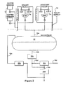
Figure 2 is a schematic diagram of the aircraft water supply system. -
Figure 3 is a sectional view of an electrically driven valve assembly, the valve assembly including a valve device, an electrical motor device, and mechanical return device. -
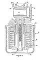
Figure 4 is a sectional view of the mechanical return device and interacting parts of the valve device. -
Figure 5 is a perspective sectional view of the valve device and the mechanical return device. -
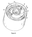
Figure 6 is a top perspective view of the mechanical return device with its cap removed. -
Figure 7 is a bottom perspective view of a returning mechanism of the mechanical return device. -
Figure 8 is a top perspective view of the mechanical return device. - Referring now to the drawings, and initially to
Figure 1 , anaircraft 10 including awater supply system 12 is shown inFigure 1 . Thesystem 12 provides potable water to respective outlets of various water-using devices 14 (e.g., sink faucets, coffee brewers, toilets, etc.) onboard theaircraft 10. - Referring additionally to
Figure 2 , the aircraftwater supply system 12 is schematically shown in more detail. Thesystem 12 can comprise atank 16 and a series ofplumbing lines 18 for supplying theoutlets 14, filling thetank 16, draining thetank 16, and/or venting thetank 16. For example, in the illustrated embodiment, thesystem 12 comprises outlet-supply lines 18a, a fill-drain line 18b, a tank-overflow (and/or tank-ventilation)line 18c, afill line 18d (for pre-flight connection to an external water source), and adrain line 18e (for post-flight connection to an external sewer). - The
system 12 can further comprise one or more valve assemblies 20 in theplumbing lines 18 for opening/closing for these lines for pre-flight, post-flight, and in-flight purposes. For example, a tank-isolation valve assembly 20a can be positioned in the tank's fill-drain line 18b; a tank-venting valve assembly 20b can be positioned in the tank-overflow line 18c, a tank-fill valve 20c can be positioned in thefill line 18d, and a drain-plug valve 20d can be positioned in thedrain line 18e. - To fill the tank 16 (e.g., during pre-flight procedures), the
valve assembly 20a, thevalve assembly 20b, and thevalve assembly 20c would each be in an opened condition. Thevalve assembly 20d would be in a closed condition. Water from an external source would be pumped through thefill line 18d, through the tank'sline 18b, and into thetank 16. Air within thetank 16 would be vented through theline 18c. - To drain the tank 16 (e.g., during post-flight procedures), the
valve assembly 20a and thevalve assembly 20d would each be in an opened condition. Thevalve assembly 20c would be in an closed condition. Water would be drained from thetank 16 throughline 18b toline 18e and into an external sewer. - During normal flight operation, the
valve assembly 20a and thevalve assembly 20c would each remain in a closed condition. Thevalve assembly 20b and thevalve assembly 20d could remain in an opened condition to allow emergency overflow drain from thetank 16. - Turning now to
Figure 3 , thevalve assembly 20 is shown isolated from the rest of thewater supply system 12. Thevalve assembly 20 comprises avalve device 30, anelectrical motor device 32, and areturn device 34. Thevalve device 30 includes avalve member 40 movable by theelectrical motor device 32 between a first position and a second position. The first position can be an opened position and the second position can be a closed position (corresponding to thevalve assembly 20 being in an opened condition and closed condition, respectively). Or the first position can be closed position and the second position can be the opened position. - One of the first position or second position can be a predetermined preferred position in the event of a power loss. In some constructions and/or circumstances, the preferred position will be the opened position, while in others it will be the closed position. If an analogy is made to a solenoid-style valve, this predetermined preferred position would correspond to the normally-opened or normally-closed design of the solenoid. In any event, for ease in explanation, the first position can be considered the preferred power-loss position.
- The
return device 34 is operably connected to thevalve member 40. Thereturn device 34 is in a mechanically relaxed condition when thevalve member 40 is in the first position and is in a mechanically biased condition when thevalve member 40 is the second position. Thus, if a power loss occurs when thevalve member 40 is in the second position, thereturn device 34 can automatically (and non-electrically) return thevalve member 40 to the first position. - The
valve device 30 includes (in addition to the valve member 40), avalve body 42 defining input-output connectors 44 and achamber 46 therebetween. In thewater supply system 12, for example, theconnectors 44 would be joined to segments of therelevant plumbing line 18. When thevalve assembly 20 is in its opened condition (i.e., thevalve member 40 is in its opened position), a fluid flow path is formed from oneconnector 44 through thechamber 46 and to theother connector 44. Heating coils (shown but not specifically numbered) can be Installed in theconnectors 44 to prevent freezing within thechamber 46. - The
valve device 30 and/or thevalve body 42 can further comprise a motor-mounting plate 48 and a return-mounting plate 50. Themounting plates motor device 32 and thereturn device 34, respectively. Thevalve member 40 is movably mounted relative to the valve body 42 (and/or themounting plates 48/50). Suitable seals (some shown, but not specifically numbered) can be situated between the various valve parts and/or between valve-interfacing parts of thedevices - The
valve member 40 can comprise a fluid-interactingportion 52 positioned within thechamber 46. Theportion 52 can have a generally spherical shape (i.e., a ball) with adiametric fluid passageway 54 therethrough. When thevalve member 40 is in its closed position (as illustrated), thechamber 46 is sealed from thefluid connectors 44 by the solid surfaces of theball portion 52. Thepassageway 54 does not communicate with the fluid in theline 18. When thevalve member 42 is moved (e.g., rotated 90°) to its opened position, thepassageway 54 forms a flow path through thechamber 46. - The
valve member 40 can comprise acrown 56 extending radially (e.g., upwardly) from theball portion 52. Thecrown 56 protrudes from the valve body 42 (and the chamber 46) and is operably connected to movement-providing members (e.g.,gears 66 introduced below) of theelectric motor device 32. - The
valve member 40 can also (or alternatively) comprise astem 58 extending radially (e.g., downwardly) from itsball portion 52. Thestem 58 also protrudes from the valve body 42 (and the chamber 46) and extends into thereturn device 34. Aguide 60 within thereturn device 34 can interact with thestem 58 during rotation of thevalve member 40. In the illustrated embodiment, thestem 58 has an internally threaded bore and thestem guide 60 has an externally threaded rod received within this bore. - The
valve member 40 can further comprise a return-drive pin 62 that interacts with thereturn device 34. In the illustrated embodiment, the return-drive pin 62 extends transversely through and beyond thestem 58. - The
motor device 32 can comprise anelectrical motor 64 that produces rotational motion, gears 66 that transfer this motion to thevalve member 40 via thecrown 56, and anelectrical brake 68. In the illustrated embodiment, when power is applied, themotor 64 and gears 66 drive thevalve member 40 from the closed position to the open position. That is, they turn theball portion 52 approximately 90° within thechamber 46. At the completion of the turn, thebrake 68 can be activated to hold the position, thereby significantly reducing power draw. If thebrake 68 is installed on the motor-side of the gear box (as shown), thegears 66 will assist in holding the valve position. - The
motor components housing 70 mounted (e.g., via brackets 72) to convenient location in theaircraft 10. Thehousing 70 can be attached to the valve's mountingplate 48 or otherwise fixed or mounted to thevalve body 42 . Electrical power/control lines can extend to themotor 64 and/orbrake 68 through asocket opening 74 in thehousing 70. - The
return device 34 comprises a returningmechanism 80 that is operably connected to thevalve member 40 and rotates therewith during electrical operation of thevalve assembly 20. Themechanism 80 can be in a mechanically relaxed condition when thevalve member 40 is in the first position, and in a biased condition when the valve member is in the second position. In any event, when thevalve member 40 is in the second position, the returningmechanism 80 biases it towards the first position. If thevalve member 40 is in the second position, and themotor device 32 loses electrical power, themechanism 80 non-electrically (e.g., mechanically) returns thevalve member 40 to the first position. - The returning
mechanism 80 can comprise aspring 82 that is wound, or biased, when thevalve member 40 moves from the first position to the second position. In the illustrated embodiment, themechanism 80 includes atorque tube 84 that winds thespring 82 during such valve movement. More specifically, thetorque tube 84 interacts with the return-drive pin 62 which turns with thestem 58 when thevalve member 40 is moved from the first position to the second position. - One end of the spring 82 (e.g., its top end) can be connected to a
cap 86. (Figure 6 .) Thecap 86 can be fixedly mounted to the valve body 42 (and/or mounting plate 50) viabolts 88 or other attachment means. A casing can surround the returningmechanism 80 and thecap 86 can be secured thereto. - The other end of the spring 82 (e.g., its bottom end) can be connected to the
torque member 84. (Figure 7 .) Thus, the top end of thespring 82 remains stationary (with the cap 86) and the bottom end of thespring 82 moves with thetorque tube 84. In this manner, thespring 82 will be "wound" when thevalve member 40 moves from the first position to the second position, and "unwound" when thevalve member 40 moves from the second position to the first position. - A valve-interacting portion of the torque member 84 (e.g., it top portion) includes engaging
ledges 90. (Figure 6 .) During electrical operation, thedrive pin 62 engages theledges 90 and pushes them as thevalve member 40 moves from the first position to the second position. (Figure 8 .) When theledges 90 reach the second position, they encounter the stop pins 92 fixedly mounted to thecap 86. In the event of electrical loss, theledges 90 will be spring biased back to the first position, thereby also pushing return-drive pin 62 (and thus the valve member 40) back to the first position. When theledges 90 reach the first position, they encounter the stop pins 92. - The
valve assembly 20 can be adapted for manual operation when electrical power is not being provided. Specifically, for example, thevalve member 40 can be turned by a handle or other suitable tool in the appropriate direction (e.g., clockwise inFigure 8 ) until thedrive pin 62 is stopped by theledges 90. This manual rotation will also drive themotor 64 and thegears 66. A manually-setvalve assembly 20 will resume to normal operation when power is applied and thevalve member 40 is placed in its electrically commanded position. - One may now appreciate that the
valve assembly 20 allows a ball-valve construction with a solenoid-style return to a predetermined position in the event of a power loss. For these and other reasons, thevalve assembly 20 can find special application in aircraft situations where solenoid-gate construction are undesirable but a loss-of-power contingency plan is necessary. Although theaircraft 10, the aircraftwater supply system 12, thevalve assembly 20, and the various component thereof have been shown and described with respect to a certain embodiment or embodiments, it is obvious that equivalent alterations and modifications will occur to others skilled in the art upon the reading and understanding of this specification and the annexed drawings. In regard to the various functions performed by the above described elements (e.g., components, assemblies, systems, devices, compositions, etc.), the terms (including a reference to a "means") used to describe such elements are intended to correspond, unless otherwise indicated, to any element which performs the specified function of the described element (i.e., that is functionally equivalent), even though not structurally equivalent to the disclosed structure which performs the function. In addition, while a particular feature may have been described above with respect to only one or more of several illustrated embodiments, such a feature may be combined with one or more other features of the other embodiments, as may be desired and advantageous for any given or particular application.
Claims (14)
- A valve assembly (20), comprising:a valve member (40);an electrical motor (64) which, when electrical power is provided, can be controlled to move the valve member (40) from a first position to a second position; anda returning mechanism (80) operably connected to the valve member (40), the returning mechanism (80) mechanically biasing the valve member (40) towards the first position when in the second position;wherein, when the valve member (40) is in the second position and the motor (64) loses electrical power, the returning mechanism (80) non-electrically returns the valve member (40) to the first position.
- A valve assembly (20) as set forth in claim 1, further comprising:an electrical brake (68) which, when electrical power is provided, locks the valve member (40) in the second position.
- A valve assembly (20) as set forth in claim 1, wherein the valve member (40) includes a ball portion (52).
- A valve assembly (20) as set forth in any of claims 1 to 3, wherein the motor (64) drives the valve member (40) approximately 90° to move it from the first position to the second position.
- A valve assembly (20) as set forth in any of claims 1 to 4, wherein the returning mechanism (80) comprises a spring (82).
- A valve assembly (20) as set forth in claim 5, wherein the returning mechanism (80) comprises a torque member (84) which winds the spring (82) when the motor (64) moves the valve member (40) from the first position to the second position.
- A valve assembly (20) as set forth in claim 1, wherein the valve member (40) may be manually moved between the first position and the second position.
- A valve assembly (20) as set forth in claim 7, wherein the electrical operation overrides manual operation when electrical power is being supplied.
- A valve assembly (20) as set forth in claim 1, wherein the returning mechanism (80) comprises a spring (82) and a torque member (84) which winds the spring (82) when the motor (64) moves the valve member (40) from the first position to the second position, and wherein the valve member (40) may be manually moved between the first position and the second position and the electrical operation overrides manual operation when electrical power is being supplied.
- A valve assembly (20) as set forth in claim 9, further comprising:an electrical brake (68) which, when electrical power is provided, locks the valve member (40) in the second position.
- A valve assembly (20) as set forth in claim 9 or 10, wherein the valve member (40) includes a ball portion (52), and the motor (64) drives the valve member (40) approximately 90° to move it from the first position to the second position.
- A valve assembly (20) as set forth in any of claims 1 to 11, wherein the first position is either an opened position or a closed position, and the second position is the other of the opened position or the closed position.
- An aircraft water supply system (12) comprising on-board water-using devices (14), plumbing lines (18), and the valve assembly (20) as set forth in any of claims 1 to 12.
- An aircraft water supply system (12) as set forth in claim 13, further comprising a water tank (16), wherein the plumbing lines (18) supply water from the tank (16) to the water-using devices (14).
Applications Claiming Priority (2)
| Application Number | Priority Date | Filing Date | Title |
|---|---|---|---|
| US95482207P | 2007-08-09 | 2007-08-09 | |
| US98743807P | 2007-11-13 | 2007-11-13 |
Publications (2)
| Publication Number | Publication Date |
|---|---|
| EP2025984A2 true EP2025984A2 (en) | 2009-02-18 |
| EP2025984A3 EP2025984A3 (en) | 2011-03-30 |
Family
ID=39970844
Family Applications (1)
| Application Number | Title | Priority Date | Filing Date |
|---|---|---|---|
| EP08252623A Withdrawn EP2025984A3 (en) | 2007-08-09 | 2008-08-01 | Valve assembly for aircraft water supply system |
Country Status (3)
| Country | Link |
|---|---|
| US (1) | US8172198B2 (en) |
| EP (1) | EP2025984A3 (en) |
| BR (1) | BRPI0803068A2 (en) |
Cited By (1)
| Publication number | Priority date | Publication date | Assignee | Title |
|---|---|---|---|---|
| WO2013014225A3 (en) * | 2011-07-28 | 2013-12-05 | Airbus Operations Gmbh | System for pipe treatment |
Families Citing this family (10)
| Publication number | Priority date | Publication date | Assignee | Title |
|---|---|---|---|---|
| EP4023916B1 (en) | 2021-01-04 | 2025-06-11 | Goodrich Corporation | Ball valve assembly |
| EP4043762B1 (en) * | 2021-02-15 | 2024-12-11 | Goodrich Corporation | Compliant joint drive assembly |
| EP4043763A1 (en) | 2021-02-15 | 2022-08-17 | Goodrich Corporation | Compliant joint drive assembly |
| EP4112978B1 (en) | 2021-06-28 | 2024-12-25 | Goodrich Corporation | Compliant joint drive assembly |
| EP4112979B1 (en) | 2021-06-29 | 2024-12-25 | Goodrich Corporation | Compliant joint drive assembly |
| EP4148305B1 (en) | 2021-09-13 | 2025-03-12 | Goodrich Corporation | Compliant joint drive assembly |
| EP4148304B1 (en) | 2021-09-13 | 2025-03-12 | Goodrich Corporation | Compliant joint drive assembly |
| US12000130B2 (en) | 2021-12-18 | 2024-06-04 | B/E Aerospace, Inc. | Vacuum toilet override systems and methods |
| EP4242501A1 (en) | 2022-03-11 | 2023-09-13 | Goodrich Corporation | Compliant joint drive assembly |
| EP4286717A1 (en) | 2022-05-31 | 2023-12-06 | B/E Aerospace, Inc. | Ball valve assembly |
Family Cites Families (31)
| Publication number | Priority date | Publication date | Assignee | Title |
|---|---|---|---|---|
| US3279744A (en) * | 1964-03-09 | 1966-10-18 | Clary Corp | Valve actuator |
| DE2123677C3 (en) | 1971-05-13 | 1974-07-25 | Research Engineering Co., Houston, Tex. (V.St.A.) | Electromotive drive device, in particular for valves |
| US3808895A (en) * | 1973-02-09 | 1974-05-07 | J Fitzwater | Electric fail-safe actuator |
| USRE30135E (en) | 1973-02-09 | 1979-11-06 | Amelia Inc. | Electric fail-safe actuator |
| US3995328A (en) | 1974-12-13 | 1976-12-07 | The Boeing Company | Vacuum toilet system |
| US4203573A (en) * | 1976-10-26 | 1980-05-20 | Erie Manufacturing Company | Reversible motor operated valve with spring assist |
| US4203537A (en) | 1977-08-25 | 1980-05-20 | Plastic-Craft, Inc. | Paint can accessory |
| JPS5825186B2 (en) | 1977-12-02 | 1983-05-26 | 株式会社神戸製鋼所 | ball valve |
| US4275470A (en) | 1979-07-18 | 1981-06-30 | Rogerson Aircraft Controls | Vacuum-flush toilet arrangement for aircraft |
| US4357719A (en) | 1979-08-20 | 1982-11-09 | Rogerson Aircraft Controls | Non recirculating method of disposing of waste products for aircrafts |
| US4757684A (en) * | 1981-04-08 | 1988-07-19 | Wright John J | Fail-safe electric actuator |
| US4533114A (en) * | 1983-02-08 | 1985-08-06 | Posi-Seal International, Inc. | Fail-safe actuator for rotary valves |
| US4669578A (en) * | 1986-03-13 | 1987-06-02 | Rikuo Fukamachi | Motor driven valve |
| NO163505C (en) | 1987-08-17 | 1990-06-06 | Norske Stats Oljeselskap | Apparatus for ball valve maintenance. |
| US4947492A (en) | 1988-04-15 | 1990-08-14 | Weber Aircraft | Swivel nozzle flush toilet system |
| US5065786A (en) | 1990-04-10 | 1991-11-19 | Monogram Sanitation, A Division Of Mag Aerospace Industries, Inc. | Flow control valve |
| US5228645A (en) | 1992-04-13 | 1993-07-20 | Marotta Scientific Controls, Inc. | Rotary ball valve with lifting ball |
| US5178361A (en) | 1992-07-02 | 1993-01-12 | The United States Of America As Represented By The Secretary Of The Army | Ball valve control |
| US5255706A (en) | 1992-11-20 | 1993-10-26 | Hycon Corporation | High-pressure ball valve with internal pressure equalization |
| DE4434437C2 (en) | 1994-09-27 | 1996-10-02 | Daimler Benz Aerospace Airbus | Vacuum toilet system in an airplane |
| US5904669A (en) | 1995-10-27 | 1999-05-18 | Fibrasonics Inc. | Magnetic ball valve and control module |
| US5823401A (en) | 1996-02-05 | 1998-10-20 | Zgoda; Roy F. | Sampling and dispensing ball-valve |
| DE19609939C1 (en) | 1996-03-14 | 1997-09-11 | Daimler Benz Aerospace Airbus | Aircraft water system |
| NL1003206C2 (en) | 1996-05-24 | 1997-11-25 | Schiphol Luchthaven Nv | Liquid drainage system for a paved surface. |
| US6012678A (en) | 1998-01-26 | 2000-01-11 | The Boeing Company | Galley vacuum waste disposal system |
| US6186471B1 (en) * | 1998-05-15 | 2001-02-13 | Taco, Inc. | Electronic motorized zone valve |
| IL130651A (en) * | 1999-06-27 | 2002-02-10 | Century Invest Ltd | Gas valve safety device |
| CN1147672C (en) | 2000-04-27 | 2004-04-28 | 吴龙洙 | Electric ball valve |
| DE10259997B4 (en) | 2002-12-20 | 2007-09-13 | Airbus Deutschland Gmbh | Aircraft toilet system |
| US7311817B2 (en) | 2003-11-14 | 2007-12-25 | Semler Industries, Inc. | System and method for sanitizing and refilling a potable water system onboard a transport vehicle |
| ITTO20050566A1 (en) | 2005-08-08 | 2007-02-09 | Ferrero Rubinetterie S R L | DRIVING SYSTEM BOTH MANUAL AND AUTOMATIC FOR VALVES, FIXING JOINT FOR THIS SYSTEM AND SUPPLY KIT OF THIS SYSTEM OR OF THAT JUNCTION |
-
2008
- 2008-07-30 US US12/182,521 patent/US8172198B2/en active Active
- 2008-08-01 EP EP08252623A patent/EP2025984A3/en not_active Withdrawn
- 2008-08-11 BR BRPI0803068-5A patent/BRPI0803068A2/en not_active Application Discontinuation
Cited By (1)
| Publication number | Priority date | Publication date | Assignee | Title |
|---|---|---|---|---|
| WO2013014225A3 (en) * | 2011-07-28 | 2013-12-05 | Airbus Operations Gmbh | System for pipe treatment |
Also Published As
| Publication number | Publication date |
|---|---|
| EP2025984A3 (en) | 2011-03-30 |
| US8172198B2 (en) | 2012-05-08 |
| US20090039306A1 (en) | 2009-02-12 |
| BRPI0803068A2 (en) | 2009-06-16 |
Similar Documents
| Publication | Publication Date | Title |
|---|---|---|
| US8172198B2 (en) | Valve assembly for aircraft water supply system | |
| CA1052362A (en) | Modulating failsafe valve actuator using differential gearing | |
| US8978687B2 (en) | Actuating device and method for displacing the actuating device | |
| WO2006068873A1 (en) | Modular actuator for subsea valves and equipment, and methods of using same | |
| US4757684A (en) | Fail-safe electric actuator | |
| US10077848B2 (en) | Motorized fluid flow control valve | |
| NO341195B1 (en) | An actuator for a valve in an underwater installation | |
| WO2013119661A1 (en) | Flushing hydrant | |
| US20090108220A1 (en) | Drain valve actuators and methods of controlling drain valves | |
| US5950427A (en) | Fail-safe electric hydraulic actuator | |
| JP3193900U (en) | 2-way lockless gear driven gas meter shut-off valve | |
| KR20050014692A (en) | Valve | |
| EP1127987B1 (en) | Flushing device for toilets | |
| US4538789A (en) | Automatic and manual actuator | |
| US5941500A (en) | Valve actuating device having a reduced impact operating mechanism | |
| JP7858063B2 (en) | Hydraulic block for hydraulic unit of electro-hydraulic two-channel non-manual brake system | |
| US20070256747A1 (en) | Motor driven valve | |
| WO2015029026A1 (en) | Fluid discharge valve | |
| US11953100B2 (en) | Valve apparatus | |
| US20110290338A1 (en) | Water supply system utilizing collected stored water and mains water supply | |
| GB2162289A (en) | Valve control device | |
| US20100181511A1 (en) | Actuator for a pilot for hydraulic control valves | |
| US20030029507A1 (en) | Fluid discharge floodgate improved for cistern aircrafts dedicated to fight fires | |
| CN112984107B (en) | Electromechanical and hydraulic control electric control automatic parking mechanism | |
| JP2013545053A (en) | Actuator for valve actuation of fluid line |
Legal Events
| Date | Code | Title | Description |
|---|---|---|---|
| PUAI | Public reference made under article 153(3) epc to a published international application that has entered the european phase |
Free format text: ORIGINAL CODE: 0009012 |
|
| AK | Designated contracting states |
Kind code of ref document: A2 Designated state(s): AT BE BG CH CY CZ DE DK EE ES FI FR GB GR HR HU IE IS IT LI LT LU LV MC MT NL NO PL PT RO SE SI SK TR |
|
| AX | Request for extension of the european patent |
Extension state: AL BA MK RS |
|
| PUAL | Search report despatched |
Free format text: ORIGINAL CODE: 0009013 |
|
| AK | Designated contracting states |
Kind code of ref document: A3 Designated state(s): AT BE BG CH CY CZ DE DK EE ES FI FR GB GR HR HU IE IS IT LI LT LU LV MC MT NL NO PL PT RO SE SI SK TR |
|
| AX | Request for extension of the european patent |
Extension state: AL BA MK RS |
|
| AKY | No designation fees paid | ||
| REG | Reference to a national code |
Ref country code: DE Ref legal event code: R108 |
|
| REG | Reference to a national code |
Ref country code: DE Ref legal event code: R108 Effective date: 20111207 |
|
| STAA | Information on the status of an ep patent application or granted ep patent |
Free format text: STATUS: THE APPLICATION IS DEEMED TO BE WITHDRAWN |
|
| 18D | Application deemed to be withdrawn |
Effective date: 20111001 |