EP2025923A1 - Method for determining a set of a valve needle and a valve seat assembly of an injection valve - Google Patents
Method for determining a set of a valve needle and a valve seat assembly of an injection valve Download PDFInfo
- Publication number
- EP2025923A1 EP2025923A1 EP07015380A EP07015380A EP2025923A1 EP 2025923 A1 EP2025923 A1 EP 2025923A1 EP 07015380 A EP07015380 A EP 07015380A EP 07015380 A EP07015380 A EP 07015380A EP 2025923 A1 EP2025923 A1 EP 2025923A1
- Authority
- EP
- European Patent Office
- Prior art keywords
- valve
- fluid
- fluid flow
- seat assembly
- needle
- Prior art date
- Legal status (The legal status is an assumption and is not a legal conclusion. Google has not performed a legal analysis and makes no representation as to the accuracy of the status listed.)
- Granted
Links
Images
Classifications
-
- F—MECHANICAL ENGINEERING; LIGHTING; HEATING; WEAPONS; BLASTING
- F02—COMBUSTION ENGINES; HOT-GAS OR COMBUSTION-PRODUCT ENGINE PLANTS
- F02M—SUPPLYING COMBUSTION ENGINES IN GENERAL WITH COMBUSTIBLE MIXTURES OR CONSTITUENTS THEREOF
- F02M65/00—Testing fuel-injection apparatus, e.g. testing injection timing ; Cleaning of fuel-injection apparatus
- F02M65/001—Measuring fuel delivery of a fuel injector
-
- F—MECHANICAL ENGINEERING; LIGHTING; HEATING; WEAPONS; BLASTING
- F02—COMBUSTION ENGINES; HOT-GAS OR COMBUSTION-PRODUCT ENGINE PLANTS
- F02M—SUPPLYING COMBUSTION ENGINES IN GENERAL WITH COMBUSTIBLE MIXTURES OR CONSTITUENTS THEREOF
- F02M61/00—Fuel-injectors not provided for in groups F02M39/00 - F02M57/00 or F02M67/00
- F02M61/16—Details not provided for in, or of interest apart from, the apparatus of groups F02M61/02 - F02M61/14
- F02M61/168—Assembling; Disassembling; Manufacturing; Adjusting
-
- F—MECHANICAL ENGINEERING; LIGHTING; HEATING; WEAPONS; BLASTING
- F02—COMBUSTION ENGINES; HOT-GAS OR COMBUSTION-PRODUCT ENGINE PLANTS
- F02M—SUPPLYING COMBUSTION ENGINES IN GENERAL WITH COMBUSTIBLE MIXTURES OR CONSTITUENTS THEREOF
- F02M2200/00—Details of fuel-injection apparatus, not otherwise provided for
- F02M2200/80—Fuel injection apparatus manufacture, repair or assembly
- F02M2200/8092—Fuel injection apparatus manufacture, repair or assembly adjusting or calibration
-
- F—MECHANICAL ENGINEERING; LIGHTING; HEATING; WEAPONS; BLASTING
- F02—COMBUSTION ENGINES; HOT-GAS OR COMBUSTION-PRODUCT ENGINE PLANTS
- F02M—SUPPLYING COMBUSTION ENGINES IN GENERAL WITH COMBUSTIBLE MIXTURES OR CONSTITUENTS THEREOF
- F02M61/00—Fuel-injectors not provided for in groups F02M39/00 - F02M57/00 or F02M67/00
- F02M61/04—Fuel-injectors not provided for in groups F02M39/00 - F02M57/00 or F02M67/00 having valves, e.g. having a plurality of valves in series
- F02M61/10—Other injectors with elongated valve bodies, i.e. of needle-valve type
- F02M61/12—Other injectors with elongated valve bodies, i.e. of needle-valve type characterised by the provision of guiding or centring means for valve bodies
-
- F—MECHANICAL ENGINEERING; LIGHTING; HEATING; WEAPONS; BLASTING
- F02—COMBUSTION ENGINES; HOT-GAS OR COMBUSTION-PRODUCT ENGINE PLANTS
- F02M—SUPPLYING COMBUSTION ENGINES IN GENERAL WITH COMBUSTIBLE MIXTURES OR CONSTITUENTS THEREOF
- F02M61/00—Fuel-injectors not provided for in groups F02M39/00 - F02M57/00 or F02M67/00
- F02M61/16—Details not provided for in, or of interest apart from, the apparatus of groups F02M61/02 - F02M61/14
- F02M61/18—Injection nozzles, e.g. having valve seats; Details of valve member seated ends, not otherwise provided for
Definitions
- the invention relates to a method for determining the capability of a valve needle and a valve seat assembly to control a desired flow rate in an injection valve, and a method for determining a set of a valve needle and a valve seat assembly of an injection valve to obtain a desired flow rate of the injection valve.
- Injection valves are in wide spread use, in particular for internal combustion engines where they may be arranged in order to dose the fluid into an intake manifold of the internal combustion engine or directly into the combustion chamber of a cylinder of the internal combustion engine.
- injection valves are manufactured in various forms in order to satisfy the various needs for the various combustion engines. Therefore, for example, their length, their diameter and also various elements of the injection valve being responsible for the way the fluid is dosed may vary in a wide range.
- injection valves may accommodate an actuator for actuating a needle of the injection valve, which may, for example, be an electromagnetic actuator or piezo electric actuator.
- the respective injection valve may be suited to dose fluids under very high pressures.
- the pressures may be in case of a gasoline engine, for example, in the range of up to 200 bar and in the case of diesel engines in the range of up to 2000 bar.
- the object of the invention is to create a method for determining the capability of a valve needle and a valve seat assembly to control a desired flow rate in an injection valve, and a method for determining a set of a valve needle and a valve seat assembly of an injection valve to obtain a desired flow rate of the injection valve which facilitates to obtain a reliable and precise function of the injection valve.
- the invention is distinguished by a method for determining the capability of a valve needle to control a desired flow rate in an injection valve, the method being carried out with a valve assembly shell comprising a valve body including a central longitudinal axis, the valve body comprising a cavity with a fluid inlet portion and a fluid outlet portion, and a valve seat assembly with a seat plate and a guiding element for guiding the valve needle, the valve needle being axially movable in the cavity, the valve needle preventing a fluid flow through the fluid outlet portion in a closing position and releasing the fluid flow through the fluid outlet portion in further positions, and the valve needle and the valve seat assembly being designed to enable a fluid flow between the fluid inlet portion and the fluid outlet portion following a first flow path through a gap between the valve needle and the guiding element of the valve seat assembly and a second flow path through the valve seat assembly.
- the method comprises the following steps:
- valve needles for injection valves are based on a functional test method and a decision based on a geometrical selection of the valve needles can be avoided. Consequently, the number of rejected valve needles can be kept small. Thus, low costs for the injection valve and a small risk of a failure of the injection valve can be obtained.
- the valve needles can be assigned to flow rate classes according to the determined flow rates.
- the invention is distinguished by a method for determining the capability of a valve seat assembly to control a desired flow rate in an injection valve, the method being carried out with a valve sub-assembly comprising a valve body including a central longitudinal axis, the valve body comprising a cavity with a fluid inlet portion and a fluid outlet portion, and a valve needle being axially movable in the cavity, the valve needle preventing a fluid flow through the fluid outlet portion in a closing position and releasing the fluid flow through the fluid outlet portion in further positions, the valve seat assembly comprising a seat plate, a guiding element for guiding the valve needle and a fluid flow directing element, and the valve needle and the valve seat assembly being designed to enable a fluid flow between the fluid inlet portion and the fluid outlet portion following a first flow path between the valve needle and the valve seat assembly and a second flow path through the valve seat assembly.
- the method comprises the following steps: coupling the valve seat assembly with the valve sub-assembly, coupling the valve sub-assembly with a fluid supply, operating the valve needle under a given set of operating conditions, thereby releasing the fluid flow through the fluid outlet portion, preventing a fluid flow through the first flow path and enabling a fluid flow through the second flow path, and measuring the fluid flow through the fluid outlet portion under a given set of operating conditions, and removing the valve seat assembly from the valve sub-assembly.
- valve seat assemblies with seat plate, guiding element and fluid flow directing element for injection valves.
- the selection of the valve seat assemblies for the injection valves is based on a functional test method and a decision based on a geometrical selection of the seat plate, the guiding element and the fluid flow directing element can be avoided. Consequently, the number of rejected valve seat assemblies can be kept small. Thus, low costs for the injection valve and a small risk of a failure of the injection valve can be obtained.
- the valve seat assemblies can be assigned to flow rate classes according to the determined flow rates.
- the invention is distinguished by a method for determining a set of a valve needle and a valve seat assembly of an injection valve to obtain a desired flow rate of the injection valve.
- the method comprises the following steps: determining a fluid flow of the valve needle in accordance with the method according to the first aspect of the invention, determining a fluid flow of the valve seat assembly in accordance with the method according to the second aspect of the invention, and selecting a combination of the valve needle according to the determined fluid flow of the valve needle and the valve seat assembly according to the determined fluid flow of the valve seat assembly to obtain the desired flow rate of the injection valve.
- valve needles and valve seat assemblies obtained by the two methods for determining the capability of valve needles and valve seat assemblies to control desired flow rates is possible. It is possible to achieve a fitting combination of valve needles and valve seat assemblies to obtain a given flow rate of the injection valve. Furthermore, valve needles and valve seat assemblies of specific flow rate classes can be matched in a desired manner. Consequently, the number of rejected injection valves can be kept small. Thus, low costs for the injection valve and a small risk of a failure of the injection valve can be obtained.
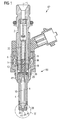
- An injection valve 62 that is in particular suitable for dosing fuel to an internal combustion engine, comprises an inlet tube 2, a housing 6 and a valve assembly 60.
- the valve assembly 60 comprises a valve body 4 with a central longitudinal axis L and a cavity 8, which takes in a valve needle 10 and preferably a part of an armature 12.
- the valve needle 10 has a surface 11 and a seat part 64 ( figure 2 ).
- a recess 16 is provided which further extends to a recess 18 of the armature 12.
- a spring 14 is arranged in the recess 16 of the inlet tube 2 and/or the recess 18 of the armature 12. Preferably, it rests on a spring seat being formed by an anti-bounce disc 20. By this the spring 14 is mechanically coupled to the needle 10.
- An adjusting tube 22 is provided in the recess 16 of the inlet tube 2.
- the adjusting tube 22 forms a further seat for the spring 14 and may be axially moved during the manufacturing process of the fluid injection valve in order to preload the spring 14 in a desired way.
- the injection nozzle 24 may be, for example, an injection hole. However, it may also be of some other type suitable for dosing fluid.
- the seat plate 26 is separate from the valve body 4.
- a lower guide 28 for guiding the needle 10 is provided.
- the lower guide 28 further comprises an orifice 70 for guiding the fluid flow.
- a fluid flow directing element 30 is provided which is arranged in the cavity 8 between the lower guide 28 and the seat plate 26.
- the fluid flow directing element 30 has the shape of a cylindrical disk.
- the seat plate 26, the lower guide 28 and the fluid flow directing element 30 are forming a valve seat assembly 32.
- the injection valve 62 is provided with an actuator unit, that comprises preferably an electromagnetic actuator, comprising a coil 36, which is preferably overmolded.
- an actuator unit that comprises preferably an electromagnetic actuator, comprising a coil 36, which is preferably overmolded.
- a valve body shell 38, the armature 12 and the inlet tube 2 are forming an electromagnetic circuit.
- the actuator unit may, however, also comprise another type of actuator, which is known to a person skilled in the art for that purpose.
- Such an actuator may be, for example, a piezoelectric actuator.
- a fluid inlet portion 42 is provided in the valve body 4 which communicates with a fluid outlet portion 44 which is a part of the cavity 8 near the seat plate 26.
- the fluid is led from the fluid inlet portion 42 to the fluid outlet portion 44.
- the axial position of the valve needle 10, which determines whether the fluid outlet portion 44 is opened or closed for a fluid flow, depends on the force balance between the spring 14 and the forces applied to the valve needle 10 by the actuator unit with the coil 36.
- the fluid flows through the fluid outlet portion 44 can be described with flow paths, in particular with a first flow path 66 and a second flow path 68.
- the fluid flow on the first flow path 66 is following the surface 11 of the valve needle 10.
- the first flow path 66 enters a gap 72 between the valve needle 10 and the lower guide 28 near the surface 11 of the valve needle 10. This fluid flow is leaving the injection nozzle 24 in axial direction.
- the second flow path 68 through the orifice 70 of the lower guide 28 represents the fluid flow distanced from the surface 11 of the valve needle 10.
- the fluid flow on the flow path 68 is passing the fluid flow directing element 30 thereby obtaining a radial velocity component of the fluid flow.
- the method for determining the capability of the valve needle 10 to control a desired flow rate in the injection valve 62 is carried out in the following manner (see figure 2 ):
- valve body 4 and the valve seat assembly 32 are forming a valve assembly shell 56 which is used as a measuring device.
- the valve needle 10 which is to be measured is inserted into the cavity 8 of the valve body 4 of the valve assembly shell 56.
- the valve assembly shell 56 is coupled with the fluid supply.
- a fluid flow through the fluid outlet portion 44 is released.
- the fluid may be a gas or a liquid.
- the fluid flow through the first flow path 66 is enabled and the fluid flow through the second flow path 68 is prevented by a first fluid flow blocking device 74.
- the valve assembly shell 56 and the first fluid flow blocking device 74 are forming a one-piece master part.
- the valve needle 10 is operated under determined operating conditions.
- the fluid flow through the fluid outlet portion 44 is measured under the determined operating conditions.
- the valve needle 10 is removed from the cavity 8 of the valve body 4 of the valve assembly shell 56.
- the method for determining the capability of the valve seat assembly 32 to control a desired flow rate in the injection valve 62 is carried out in the following way (see figure 3 ):
- valve body 4 and the valve needle 10 are forming a valve sub-assembly 58 which is used as a measuring device.
- the valve seat assembly 32 which is to be measured is inserted into the valve sub-assembly 58.
- the valve sub-assembly 58 is coupled with the fluid supply.
- the fluid flow is released through the fluid outlet portion 44.
- the fluid may be a gas or a liquid.
- the fluid flow through the second flow path 68 is enabled and the fluid flow through the first flow path 66 is prevented by a second fluid flow blocking device 76.
- the valve needle 10 is operated under a certain set of operating conditions.
- the fluid flow through the fluid outlet portion 44 is determined under the certain set of operating conditions.
- the valve seat assembly 32 is removed from the valve sub-assembly 58.
- a combination of the valve needle 10 according to the determined fluid flow of the valve needle 10 and the valve seat assembly 32 according to the determined fluid flow of the valve seat assembly 32 is selected to form a couple of the valve needle 10 and the valve seat assembly 32 to obtain the required flow rate of the injection valve 62.
Landscapes
- Engineering & Computer Science (AREA)
- Chemical & Material Sciences (AREA)
- Combustion & Propulsion (AREA)
- Mechanical Engineering (AREA)
- General Engineering & Computer Science (AREA)
- Manufacturing & Machinery (AREA)
- Fuel-Injection Apparatus (AREA)
Abstract
Description
- The invention relates to a method for determining the capability of a valve needle and a valve seat assembly to control a desired flow rate in an injection valve, and a method for determining a set of a valve needle and a valve seat assembly of an injection valve to obtain a desired flow rate of the injection valve.
- Injection valves are in wide spread use, in particular for internal combustion engines where they may be arranged in order to dose the fluid into an intake manifold of the internal combustion engine or directly into the combustion chamber of a cylinder of the internal combustion engine.
- Injection valves are manufactured in various forms in order to satisfy the various needs for the various combustion engines. Therefore, for example, their length, their diameter and also various elements of the injection valve being responsible for the way the fluid is dosed may vary in a wide range. In addition to that, injection valves may accommodate an actuator for actuating a needle of the injection valve, which may, for example, be an electromagnetic actuator or piezo electric actuator.
- In order to enhance the combustion process in view of the creation of unwanted emissions, the respective injection valve may be suited to dose fluids under very high pressures. The pressures may be in case of a gasoline engine, for example, in the range of up to 200 bar and in the case of diesel engines in the range of up to 2000 bar.
- The object of the invention is to create a method for determining the capability of a valve needle and a valve seat assembly to control a desired flow rate in an injection valve, and a method for determining a set of a valve needle and a valve seat assembly of an injection valve to obtain a desired flow rate of the injection valve which facilitates to obtain a reliable and precise function of the injection valve.
- These objects are achieved by the features of the independent claims.
- According to a first aspect the invention is distinguished by a method for determining the capability of a valve needle to control a desired flow rate in an injection valve, the method being carried out with a valve assembly shell comprising a valve body including a central longitudinal axis, the valve body comprising a cavity with a fluid inlet portion and a fluid outlet portion, and a valve seat assembly with a seat plate and a guiding element for guiding the valve needle, the valve needle being axially movable in the cavity, the valve needle preventing a fluid flow through the fluid outlet portion in a closing position and releasing the fluid flow through the fluid outlet portion in further positions, and the valve needle and the valve seat assembly being designed to enable a fluid flow between the fluid inlet portion and the fluid outlet portion following a first flow path through a gap between the valve needle and the guiding element of the valve seat assembly and a second flow path through the valve seat assembly. The method comprises the following steps:
- inserting the valve needle into the cavity of the valve body of the valve assembly shell, coupling the valve assembly shell with a fluid supply, operating the valve needle under a given set of operating conditions, thereby releasing the fluid flow through the fluid outlet portion, preventing a fluid flow through the second flow path and enabling a fluid flow through the first flow path, measuring the fluid flow through the fluid outlet portion under the given set of operating conditions, and removing the valve needle from the cavity of the valve body of the valve assembly shell.
- This has he advantage, that a reliable selection of suitable valve needles for injection valves is possible. The selection of the valve needles for the injection valves is based on a functional test method and a decision based on a geometrical selection of the valve needles can be avoided. Consequently, the number of rejected valve needles can be kept small. Thus, low costs for the injection valve and a small risk of a failure of the injection valve can be obtained. Finally, the valve needles can be assigned to flow rate classes according to the determined flow rates.
- According to a second aspect the invention is distinguished by a method for determining the capability of a valve seat assembly to control a desired flow rate in an injection valve, the method being carried out with a valve sub-assembly comprising a valve body including a central longitudinal axis, the valve body comprising a cavity with a fluid inlet portion and a fluid outlet portion, and a valve needle being axially movable in the cavity, the valve needle preventing a fluid flow through the fluid outlet portion in a closing position and releasing the fluid flow through the fluid outlet portion in further positions, the valve seat assembly comprising a seat plate, a guiding element for guiding the valve needle and a fluid flow directing element, and the valve needle and the valve seat assembly being designed to enable a fluid flow between the fluid inlet portion and the fluid outlet portion following a first flow path between the valve needle and the valve seat assembly and a second flow path through the valve seat assembly. The method comprises the following steps: coupling the valve seat assembly with the valve sub-assembly, coupling the valve sub-assembly with a fluid supply, operating the valve needle under a given set of operating conditions, thereby releasing the fluid flow through the fluid outlet portion, preventing a fluid flow through the first flow path and enabling a fluid flow through the second flow path, and measuring the fluid flow through the fluid outlet portion under a given set of operating conditions, and removing the valve seat assembly from the valve sub-assembly.
- This has the advantage, that a reliable selection of suitable valve seat assemblies with seat plate, guiding element and fluid flow directing element for injection valves is possible. The selection of the valve seat assemblies for the injection valves is based on a functional test method and a decision based on a geometrical selection of the seat plate, the guiding element and the fluid flow directing element can be avoided. Consequently, the number of rejected valve seat assemblies can be kept small. Thus, low costs for the injection valve and a small risk of a failure of the injection valve can be obtained. Finally, the valve seat assemblies can be assigned to flow rate classes according to the determined flow rates.
- According to a third aspect the invention is distinguished by a method for determining a set of a valve needle and a valve seat assembly of an injection valve to obtain a desired flow rate of the injection valve. The method comprises the following steps: determining a fluid flow of the valve needle in accordance with the method according to the first aspect of the invention, determining a fluid flow of the valve seat assembly in accordance with the method according to the second aspect of the invention, and selecting a combination of the valve needle according to the determined fluid flow of the valve needle and the valve seat assembly according to the determined fluid flow of the valve seat assembly to obtain the desired flow rate of the injection valve.
- This has the advantage, that a simple determination of appropriate combinations of valve needles and valve seat assemblies obtained by the two methods for determining the capability of valve needles and valve seat assemblies to control desired flow rates is possible. It is possible to achieve a fitting combination of valve needles and valve seat assemblies to obtain a given flow rate of the injection valve. Furthermore, valve needles and valve seat assemblies of specific flow rate classes can be matched in a desired manner. Consequently, the number of rejected injection valves can be kept small. Thus, low costs for the injection valve and a small risk of a failure of the injection valve can be obtained.
- Exemplary embodiments of the invention are explained in the following with the aid of schematic drawings. These are as follows:
- Figure 1
- an injection valve with a valve assembly in a longitudinal section view,
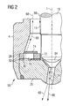
- Figure 2
- section II of the valve assembly of the injection valve according to
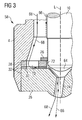
figure 1 in a longitudinal section view according to a first operating condition, and - Figure 3
- section II of the valve assembly of the injection valve according to
figure 1 in a longitudinal section view according to a second operating condition. - Elements of the same design and function that appear in different illustrations are identified by the same reference character.
- An
injection valve 62, that is in particular suitable for dosing fuel to an internal combustion engine, comprises aninlet tube 2, ahousing 6 and avalve assembly 60. - The
valve assembly 60 comprises avalve body 4 with a central longitudinal axis L and acavity 8, which takes in avalve needle 10 and preferably a part of anarmature 12. Thevalve needle 10 has a surface 11 and a seat part 64 (figure 2 ). In the inlet tube 2 arecess 16 is provided which further extends to arecess 18 of thearmature 12. Aspring 14 is arranged in therecess 16 of theinlet tube 2 and/or therecess 18 of thearmature 12. Preferably, it rests on a spring seat being formed by ananti-bounce disc 20. By this thespring 14 is mechanically coupled to theneedle 10. An adjustingtube 22 is provided in therecess 16 of theinlet tube 2. The adjustingtube 22 forms a further seat for thespring 14 and may be axially moved during the manufacturing process of the fluid injection valve in order to preload thespring 14 in a desired way. - In a closing position of the
needle 10 it sealingly rests on aseat plate 26 by this preventing a fluid flow through at least oneinjection nozzle 24. Theinjection nozzle 24 may be, for example, an injection hole. However, it may also be of some other type suitable for dosing fluid. Theseat plate 26 is separate from thevalve body 4. In addition to that alower guide 28 for guiding theneedle 10 is provided. Thelower guide 28 further comprises anorifice 70 for guiding the fluid flow. - Additionally, a fluid
flow directing element 30 is provided which is arranged in thecavity 8 between thelower guide 28 and theseat plate 26. Preferably, the fluidflow directing element 30 has the shape of a cylindrical disk. - The
seat plate 26, thelower guide 28 and the fluidflow directing element 30 are forming avalve seat assembly 32. - The
injection valve 62 is provided with an actuator unit, that comprises preferably an electromagnetic actuator, comprising acoil 36, which is preferably overmolded. Avalve body shell 38, thearmature 12 and theinlet tube 2 are forming an electromagnetic circuit. The actuator unit may, however, also comprise another type of actuator, which is known to a person skilled in the art for that purpose. Such an actuator may be, for example, a piezoelectric actuator. - A
fluid inlet portion 42 is provided in thevalve body 4 which communicates with afluid outlet portion 44 which is a part of thecavity 8 near theseat plate 26. - In the following, the function of the
injection valve 10 is described: - The fluid is led from the
fluid inlet portion 42 to thefluid outlet portion 44. The axial position of thevalve needle 10, which determines whether thefluid outlet portion 44 is opened or closed for a fluid flow, depends on the force balance between thespring 14 and the forces applied to thevalve needle 10 by the actuator unit with thecoil 36. - The fluid flows through the
fluid outlet portion 44 can be described with flow paths, in particular with afirst flow path 66 and asecond flow path 68. - The fluid flow on the
first flow path 66 is following the surface 11 of thevalve needle 10. - As can be seen in
figure 2 , thefirst flow path 66 enters agap 72 between thevalve needle 10 and thelower guide 28 near the surface 11 of thevalve needle 10. This fluid flow is leaving theinjection nozzle 24 in axial direction. - As can be seen in
figure 3 , thesecond flow path 68 through theorifice 70 of thelower guide 28 represents the fluid flow distanced from the surface 11 of thevalve needle 10. The fluid flow on theflow path 68 is passing the fluidflow directing element 30 thereby obtaining a radial velocity component of the fluid flow. - In the following, the method for determining the capability of the valve needle and the valve seat assembly to control a desired flow rate in the injection valve, and the method for determining a set of the valve needle and the valve seat assembly of the injection valve to obtain a desired flow rate of the injection valve are described in detail:
- The method for determining the capability of the
valve needle 10 to control a desired flow rate in theinjection valve 62 is carried out in the following manner (seefigure 2 ): - The
valve body 4 and thevalve seat assembly 32 are forming avalve assembly shell 56 which is used as a measuring device. Thevalve needle 10 which is to be measured is inserted into thecavity 8 of thevalve body 4 of thevalve assembly shell 56. Thevalve assembly shell 56 is coupled with the fluid supply. A fluid flow through thefluid outlet portion 44 is released. The fluid may be a gas or a liquid. The fluid flow through thefirst flow path 66 is enabled and the fluid flow through thesecond flow path 68 is prevented by a first fluidflow blocking device 74. Alternatively, thevalve assembly shell 56 and the first fluidflow blocking device 74 are forming a one-piece master part. Thevalve needle 10 is operated under determined operating conditions. Furthermore, the fluid flow through thefluid outlet portion 44 is measured under the determined operating conditions. Finally, after having measured the fluid flow through thefluid outlet portion 44, thevalve needle 10 is removed from thecavity 8 of thevalve body 4 of thevalve assembly shell 56. - The method for determining the capability of the
valve seat assembly 32 to control a desired flow rate in theinjection valve 62 is carried out in the following way (seefigure 3 ): - The
valve body 4 and thevalve needle 10 are forming avalve sub-assembly 58 which is used as a measuring device. Thevalve seat assembly 32 which is to be measured is inserted into thevalve sub-assembly 58. Thevalve sub-assembly 58 is coupled with the fluid supply. The fluid flow is released through thefluid outlet portion 44. The fluid may be a gas or a liquid. The fluid flow through thesecond flow path 68 is enabled and the fluid flow through thefirst flow path 66 is prevented by a second fluidflow blocking device 76. Thevalve needle 10 is operated under a certain set of operating conditions. The fluid flow through thefluid outlet portion 44 is determined under the certain set of operating conditions. Finally, thevalve seat assembly 32 is removed from thevalve sub-assembly 58. - In a further step, a combination of the
valve needle 10 according to the determined fluid flow of thevalve needle 10 and thevalve seat assembly 32 according to the determined fluid flow of thevalve seat assembly 32 is selected to form a couple of thevalve needle 10 and thevalve seat assembly 32 to obtain the required flow rate of theinjection valve 62.
Claims (3)
- Method for determining the capability of a valve needle (10) to control a desired flow rate in an injection valve (62),
the method being carried out with a valve assembly shell (56) comprising- a valve body (4) including a central longitudinal axis (L), the valve body (4) comprising a cavity (8) with a fluid inlet portion (42) and a fluid outlet portion (44), and- a valve seat assembly (32) with a seat plate (26) and a guiding element (28) for guiding the valve needle (10),the valve needle (10) being axially movable in the cavity (24), the valve needle (10) preventing a fluid flow through the fluid outlet portion (44) in a closing position and releasing the fluid flow through the fluid outlet portion (44) in further positions, and the valve needle (10) and the valve seat assembly (32) being designed to enable a fluid flow between the fluid inlet portion (42) and the fluid outlet portion (44) following a first flow path (66) through a gap (74) between the valve needle (10) and the guiding element (28) of the valve seat assembly (32) and a second flow path (68) through the valve seat assembly (32),
the method comprising the following steps:- inserting the valve needle (10) into the cavity (8) of the valve body (4) of the valve assembly shell (56),- coupling the valve assembly shell (56) with a fluid supply,- operating the valve needle (10) under a given set of operating conditions, thereby releasing the fluid flow through the fluid outlet portion (44), preventing a fluid flow through the second flow path (68) and enabling a fluid flow through the first flow path (66),- measuring the fluid flow through the fluid outlet portion (44) under the given set of operating conditions, and- removing the valve needle (10) from the cavity (8) of the valve body (4) of the valve assembly shell (56). - Method for determining the capability of a valve seat assembly (32) to control a desired flow rate in an injection valve (62),
the method being carried out with a valve sub-assembly (58) comprising- a valve body (4) including a central longitudinal axis (L), the valve body (4) comprising a cavity (8) with a fluid inlet portion (42) and a fluid outlet portion (44), and- a valve needle (10) being axially movable in the cavity (24), the valve needle (10) preventing a fluid flow through the fluid outlet portion (44) in a closing position and releasing the fluid flow through the fluid outlet portion (44) in further positions,the valve seat assembly (32) comprising a seat plate (26), a guiding element (28) for guiding the valve needle (10) and a fluid flow directing element (30),
and the valve needle (10) and the valve seat assembly (32) being designed to enable a fluid flow between the fluid inlet portion (42) and the fluid outlet portion (44) following a first flow path (66) between the valve needle (10) and the valve seat assembly (32) and a second flow path (68) through the valve seat assembly (32),
the method comprising the following steps:- coupling the valve seat assembly (32) with the valve sub-assembly (58),- coupling the valve sub-assembly (58) with a fluid supply,- operating the valve needle (10) under a given set of operating conditions, thereby releasing the fluid flow through the fluid outlet portion (44), preventing a fluid flow through the first flow path (66) and enabling a fluid flow through the second flow path (68), and- measuring the fluid flow through the fluid outlet portion (44) under a given set of operating conditions, and- removing the valve seat assembly (32) from the valve sub-assembly (58). - Method for determining a set of a valve needle (10) and a valve seat assembly (32) of an injection valve (62) to obtain a desired flow rate of the injection valve (62),
the method comprising the following steps:- determining a fluid flow of the valve needle (10) in accordance with the method of claim 1,- determining a fluid flow of the valve seat assembly (32) in accordance with the method of claim 2, and- selecting a combination of the valve needle (10) according to the determined fluid flow of the valve needle (10) and the valve seat assembly (32) according to the determined fluid flow of the valve seat assembly (32) to obtain the desired flow rate of the injection valve (62).
Priority Applications (2)
| Application Number | Priority Date | Filing Date | Title |
|---|---|---|---|
| EP20070015380 EP2025923B1 (en) | 2007-08-06 | 2007-08-06 | Method for determining a set of a valve needle and a valve seat assembly of an injection valve |
| DE200760013891 DE602007013891D1 (en) | 2007-08-06 | 2007-08-06 | Method for determining the composition of a valve needle and a valve seat arrangement of an injection valve |
Applications Claiming Priority (1)
| Application Number | Priority Date | Filing Date | Title |
|---|---|---|---|
| EP20070015380 EP2025923B1 (en) | 2007-08-06 | 2007-08-06 | Method for determining a set of a valve needle and a valve seat assembly of an injection valve |
Publications (2)
| Publication Number | Publication Date |
|---|---|
| EP2025923A1 true EP2025923A1 (en) | 2009-02-18 |
| EP2025923B1 EP2025923B1 (en) | 2011-04-13 |
Family
ID=39078367
Family Applications (1)
| Application Number | Title | Priority Date | Filing Date |
|---|---|---|---|
| EP20070015380 Active EP2025923B1 (en) | 2007-08-06 | 2007-08-06 | Method for determining a set of a valve needle and a valve seat assembly of an injection valve |
Country Status (2)
| Country | Link |
|---|---|
| EP (1) | EP2025923B1 (en) |
| DE (1) | DE602007013891D1 (en) |
Citations (3)
| Publication number | Priority date | Publication date | Assignee | Title |
|---|---|---|---|---|
| US6179227B1 (en) * | 1997-02-06 | 2001-01-30 | Siemens Automotive Corporation | Pressure swirl generator for a fuel injector |
| WO2002033247A2 (en) * | 2000-10-20 | 2002-04-25 | Robert Bosch Gmbh | Fuel injection valve |
| EP1811166A1 (en) * | 2006-01-24 | 2007-07-25 | Siemens Aktiengesellschaft | Valve assembly for an injection valve and injection valve |
-
2007
- 2007-08-06 EP EP20070015380 patent/EP2025923B1/en active Active
- 2007-08-06 DE DE200760013891 patent/DE602007013891D1/en active Active
Patent Citations (3)
| Publication number | Priority date | Publication date | Assignee | Title |
|---|---|---|---|---|
| US6179227B1 (en) * | 1997-02-06 | 2001-01-30 | Siemens Automotive Corporation | Pressure swirl generator for a fuel injector |
| WO2002033247A2 (en) * | 2000-10-20 | 2002-04-25 | Robert Bosch Gmbh | Fuel injection valve |
| EP1811166A1 (en) * | 2006-01-24 | 2007-07-25 | Siemens Aktiengesellschaft | Valve assembly for an injection valve and injection valve |
Also Published As
| Publication number | Publication date |
|---|---|
| EP2025923B1 (en) | 2011-04-13 |
| DE602007013891D1 (en) | 2011-05-26 |
Similar Documents
| Publication | Publication Date | Title |
|---|---|---|
| EP2535552B1 (en) | Valve assembly for an injection valve and injection valve | |
| EP2333297B1 (en) | Valve assembly for an injection valve and injection valve | |
| EP2000662B1 (en) | Adjusting and filter arrangement for an injection valve and injection valve | |
| US8919372B2 (en) | Valve assembly for an injection valve and injection valve | |
| US7607636B2 (en) | Valve assembly for an injection valve and injection valve | |
| EP2375051A1 (en) | Valve assembly for an injection valve and injection valve | |
| EP1995447A1 (en) | Valve assembly for an injection valve and injection valve | |
| EP2025923B1 (en) | Method for determining a set of a valve needle and a valve seat assembly of an injection valve | |
| EP2568155B1 (en) | Valve assembly and injection valve | |
| US20080023578A1 (en) | Valve Assembly for an Injection Valve and Injection Valve | |
| EP2436909A1 (en) | Valve assembly for an injection valve and injection valve | |
| EP2354531A1 (en) | Valve assembly for an injection valve and injection valve | |
| EP2218900A1 (en) | Valve assembly for an injection valve and injection valve | |
| EP2166220A1 (en) | Injection valve | |
| EP2172641B1 (en) | Actuator and injection valve | |
| EP2466109A1 (en) | Valve assembly for an injection valve and injection valve | |
| EP2426350A1 (en) | Valve assembly for an injection valve and injection valve | |
| EP2282042A1 (en) | Valve assembly and injection valve | |
| EP1898082B1 (en) | Valve assembly for an injection valve and injection valve | |
| EP1816344B1 (en) | Valve assembly for an injection valve and injection valve | |
| EP2363595A1 (en) | Valve assembly for an injection valve and injection valve | |
| EP2241743B1 (en) | Valve assembly for an injection valve and injection valve | |
| EP2700808A1 (en) | Seat plate and valve assembly for an injection valve | |
| EP2216542A1 (en) | Valve assembly for an injection valve and injection valve | |
| EP1793120A1 (en) | Valve assembly for an injection valve |
Legal Events
| Date | Code | Title | Description |
|---|---|---|---|
| PUAI | Public reference made under article 153(3) epc to a published international application that has entered the european phase |
Free format text: ORIGINAL CODE: 0009012 |
|
| AK | Designated contracting states |
Kind code of ref document: A1 Designated state(s): AT BE BG CH CY CZ DE DK EE ES FI FR GB GR HU IE IS IT LI LT LU LV MC MT NL PL PT RO SE SI SK TR |
|
| AX | Request for extension of the european patent |
Extension state: AL BA HR MK RS |
|
| 17P | Request for examination filed |
Effective date: 20090818 |
|
| AKX | Designation fees paid |
Designated state(s): DE FR IT |
|
| GRAP | Despatch of communication of intention to grant a patent |
Free format text: ORIGINAL CODE: EPIDOSNIGR1 |
|
| GRAS | Grant fee paid |
Free format text: ORIGINAL CODE: EPIDOSNIGR3 |
|
| GRAA | (expected) grant |
Free format text: ORIGINAL CODE: 0009210 |
|
| AK | Designated contracting states |
Kind code of ref document: B1 Designated state(s): DE FR IT |
|
| REF | Corresponds to: |
Ref document number: 602007013891 Country of ref document: DE Date of ref document: 20110526 Kind code of ref document: P |
|
| REG | Reference to a national code |
Ref country code: DE Ref legal event code: R096 Ref document number: 602007013891 Country of ref document: DE Effective date: 20110526 |
|
| PLBE | No opposition filed within time limit |
Free format text: ORIGINAL CODE: 0009261 |
|
| STAA | Information on the status of an ep patent application or granted ep patent |
Free format text: STATUS: NO OPPOSITION FILED WITHIN TIME LIMIT |
|
| 26N | No opposition filed |
Effective date: 20120116 |
|
| REG | Reference to a national code |
Ref country code: DE Ref legal event code: R097 Ref document number: 602007013891 Country of ref document: DE Effective date: 20120116 |
|
| REG | Reference to a national code |
Ref country code: FR Ref legal event code: PLFP Year of fee payment: 10 |
|
| REG | Reference to a national code |
Ref country code: FR Ref legal event code: PLFP Year of fee payment: 11 |
|
| REG | Reference to a national code |
Ref country code: FR Ref legal event code: PLFP Year of fee payment: 12 |
|
| REG | Reference to a national code |
Ref country code: DE Ref legal event code: R084 Ref document number: 602007013891 Country of ref document: DE |
|
| REG | Reference to a national code |
Ref country code: DE Ref legal event code: R081 Ref document number: 602007013891 Country of ref document: DE Owner name: VITESCO TECHNOLOGIES GMBH, DE Free format text: FORMER OWNER: CONTINENTAL AUTOMOTIVE GMBH, 30165 HANNOVER, DE |
|
| REG | Reference to a national code |
Ref country code: DE Ref legal event code: R081 Ref document number: 602007013891 Country of ref document: DE Owner name: SCHAEFFLER TECHNOLOGIES AG & CO. KG, DE Free format text: FORMER OWNER: VITESCO TECHNOLOGIES GMBH, 30165 HANNOVER, DE Ref country code: DE Ref legal event code: R081 Ref document number: 602007013891 Country of ref document: DE Owner name: VITESCO TECHNOLOGIES GMBH, DE Free format text: FORMER OWNER: VITESCO TECHNOLOGIES GMBH, 30165 HANNOVER, DE |
|
| P01 | Opt-out of the competence of the unified patent court (upc) registered |
Effective date: 20230530 |
|
| REG | Reference to a national code |
Ref country code: DE Ref legal event code: R081 Ref document number: 602007013891 Country of ref document: DE Owner name: SCHAEFFLER TECHNOLOGIES AG & CO. KG, DE Free format text: FORMER OWNER: VITESCO TECHNOLOGIES GMBH, 93055 REGENSBURG, DE |
|
| PGFP | Annual fee paid to national office [announced via postgrant information from national office to epo] |
Ref country code: DE Payment date: 20250831 Year of fee payment: 19 |
|
| PGFP | Annual fee paid to national office [announced via postgrant information from national office to epo] |
Ref country code: IT Payment date: 20250825 Year of fee payment: 19 |
|
| PGFP | Annual fee paid to national office [announced via postgrant information from national office to epo] |
Ref country code: FR Payment date: 20250829 Year of fee payment: 19 |