EP2025905A1 - Control system for a variable valve train of an internal combustion engine - Google Patents
Control system for a variable valve train of an internal combustion engine Download PDFInfo
- Publication number
- EP2025905A1 EP2025905A1 EP08012542A EP08012542A EP2025905A1 EP 2025905 A1 EP2025905 A1 EP 2025905A1 EP 08012542 A EP08012542 A EP 08012542A EP 08012542 A EP08012542 A EP 08012542A EP 2025905 A1 EP2025905 A1 EP 2025905A1
- Authority
- EP
- European Patent Office
- Prior art keywords
- control input
- hold
- control
- deviation
- feedback
- Prior art date
- Legal status (The legal status is an assumption and is not a legal conclusion. Google has not performed a legal analysis and makes no representation as to the accuracy of the status listed.)
- Granted
Links
- 238000002485 combustion reaction Methods 0.000 title claims description 9
- 238000013459 approach Methods 0.000 claims abstract description 14
- 238000004364 calculation method Methods 0.000 claims description 58
- 230000007246 mechanism Effects 0.000 claims description 37
- 238000000034 method Methods 0.000 claims description 35
- 230000006870 function Effects 0.000 description 39
- 238000012546 transfer Methods 0.000 description 32
- 230000008569 process Effects 0.000 description 25
- 238000010586 diagram Methods 0.000 description 17
- 238000007493 shaping process Methods 0.000 description 14
- 230000008859 change Effects 0.000 description 8
- 239000000446 fuel Substances 0.000 description 8
- 238000002347 injection Methods 0.000 description 6
- 239000007924 injection Substances 0.000 description 6
- 239000002826 coolant Substances 0.000 description 5
- 238000001514 detection method Methods 0.000 description 5
- 230000004069 differentiation Effects 0.000 description 5
- 238000001914 filtration Methods 0.000 description 5
- 230000010354 integration Effects 0.000 description 4
- 208000032325 CEBPE-associated autoinflammation-immunodeficiency-neutrophil dysfunction syndrome Diseases 0.000 description 3
- 101150037092 CHLD gene Proteins 0.000 description 3
- 238000012937 correction Methods 0.000 description 3
- 101150042828 csa1 gene Proteins 0.000 description 2
- 230000007423 decrease Effects 0.000 description 2
- 230000000694 effects Effects 0.000 description 2
- 230000004048 modification Effects 0.000 description 2
- 238000012986 modification Methods 0.000 description 2
- 239000003921 oil Substances 0.000 description 2
- 229920006395 saturated elastomer Polymers 0.000 description 2
- 230000005540 biological transmission Effects 0.000 description 1
- 230000010485 coping Effects 0.000 description 1
- 238000013016 damping Methods 0.000 description 1
- 239000010687 lubricating oil Substances 0.000 description 1
- 230000002093 peripheral effect Effects 0.000 description 1
- 238000012545 processing Methods 0.000 description 1
- 230000009467 reduction Effects 0.000 description 1
- 238000011144 upstream manufacturing Methods 0.000 description 1
Images







Classifications
-
- F—MECHANICAL ENGINEERING; LIGHTING; HEATING; WEAPONS; BLASTING
- F02—COMBUSTION ENGINES; HOT-GAS OR COMBUSTION-PRODUCT ENGINE PLANTS
- F02D—CONTROLLING COMBUSTION ENGINES
- F02D41/00—Electrical control of supply of combustible mixture or its constituents
- F02D41/0002—Controlling intake air
-
- F—MECHANICAL ENGINEERING; LIGHTING; HEATING; WEAPONS; BLASTING
- F01—MACHINES OR ENGINES IN GENERAL; ENGINE PLANTS IN GENERAL; STEAM ENGINES
- F01L—CYCLICALLY OPERATING VALVES FOR MACHINES OR ENGINES
- F01L1/00—Valve-gear or valve arrangements, e.g. lift-valve gear
- F01L1/34—Valve-gear or valve arrangements, e.g. lift-valve gear characterised by the provision of means for changing the timing of the valves without changing the duration of opening and without affecting the magnitude of the valve lift
-
- F—MECHANICAL ENGINEERING; LIGHTING; HEATING; WEAPONS; BLASTING
- F01—MACHINES OR ENGINES IN GENERAL; ENGINE PLANTS IN GENERAL; STEAM ENGINES
- F01L—CYCLICALLY OPERATING VALVES FOR MACHINES OR ENGINES
- F01L13/00—Modifications of valve-gear to facilitate reversing, braking, starting, changing compression ratio, or other specific operations
- F01L13/0015—Modifications of valve-gear to facilitate reversing, braking, starting, changing compression ratio, or other specific operations for optimising engine performances by modifying valve lift according to various working parameters, e.g. rotational speed, load, torque
- F01L13/0063—Modifications of valve-gear to facilitate reversing, braking, starting, changing compression ratio, or other specific operations for optimising engine performances by modifying valve lift according to various working parameters, e.g. rotational speed, load, torque by modification of cam contact point by displacing an intermediate lever or wedge-shaped intermediate element, e.g. Tourtelot
-
- F—MECHANICAL ENGINEERING; LIGHTING; HEATING; WEAPONS; BLASTING
- F02—COMBUSTION ENGINES; HOT-GAS OR COMBUSTION-PRODUCT ENGINE PLANTS
- F02D—CONTROLLING COMBUSTION ENGINES
- F02D13/00—Controlling the engine output power by varying inlet or exhaust valve operating characteristics, e.g. timing
- F02D13/02—Controlling the engine output power by varying inlet or exhaust valve operating characteristics, e.g. timing during engine operation
- F02D13/0203—Variable control of intake and exhaust valves
- F02D13/0207—Variable control of intake and exhaust valves changing valve lift or valve lift and timing
- F02D13/0211—Variable control of intake and exhaust valves changing valve lift or valve lift and timing the change of valve timing is caused by the change in valve lift, i.e. both valve lift and timing are functionally related
-
- F—MECHANICAL ENGINEERING; LIGHTING; HEATING; WEAPONS; BLASTING
- F02—COMBUSTION ENGINES; HOT-GAS OR COMBUSTION-PRODUCT ENGINE PLANTS
- F02D—CONTROLLING COMBUSTION ENGINES
- F02D41/00—Electrical control of supply of combustible mixture or its constituents
- F02D41/02—Circuit arrangements for generating control signals
- F02D41/14—Introducing closed-loop corrections
- F02D41/1401—Introducing closed-loop corrections characterised by the control or regulation method
-
- F—MECHANICAL ENGINEERING; LIGHTING; HEATING; WEAPONS; BLASTING
- F02—COMBUSTION ENGINES; HOT-GAS OR COMBUSTION-PRODUCT ENGINE PLANTS
- F02D—CONTROLLING COMBUSTION ENGINES
- F02D41/00—Electrical control of supply of combustible mixture or its constituents
- F02D41/02—Circuit arrangements for generating control signals
- F02D41/14—Introducing closed-loop corrections
- F02D41/1438—Introducing closed-loop corrections using means for determining characteristics of the combustion gases; Sensors therefor
- F02D41/1477—Introducing closed-loop corrections using means for determining characteristics of the combustion gases; Sensors therefor characterised by the regulation circuit or part of it,(e.g. comparator, PI regulator, output)
-
- F—MECHANICAL ENGINEERING; LIGHTING; HEATING; WEAPONS; BLASTING
- F01—MACHINES OR ENGINES IN GENERAL; ENGINE PLANTS IN GENERAL; STEAM ENGINES
- F01L—CYCLICALLY OPERATING VALVES FOR MACHINES OR ENGINES
- F01L1/00—Valve-gear or valve arrangements, e.g. lift-valve gear
- F01L1/12—Transmitting gear between valve drive and valve
- F01L1/18—Rocking arms or levers
- F01L1/185—Overhead end-pivot rocking arms
-
- F—MECHANICAL ENGINEERING; LIGHTING; HEATING; WEAPONS; BLASTING
- F01—MACHINES OR ENGINES IN GENERAL; ENGINE PLANTS IN GENERAL; STEAM ENGINES
- F01L—CYCLICALLY OPERATING VALVES FOR MACHINES OR ENGINES
- F01L13/00—Modifications of valve-gear to facilitate reversing, braking, starting, changing compression ratio, or other specific operations
- F01L13/0015—Modifications of valve-gear to facilitate reversing, braking, starting, changing compression ratio, or other specific operations for optimising engine performances by modifying valve lift according to various working parameters, e.g. rotational speed, load, torque
- F01L13/0063—Modifications of valve-gear to facilitate reversing, braking, starting, changing compression ratio, or other specific operations for optimising engine performances by modifying valve lift according to various working parameters, e.g. rotational speed, load, torque by modification of cam contact point by displacing an intermediate lever or wedge-shaped intermediate element, e.g. Tourtelot
- F01L2013/0068—Modifications of valve-gear to facilitate reversing, braking, starting, changing compression ratio, or other specific operations for optimising engine performances by modifying valve lift according to various working parameters, e.g. rotational speed, load, torque by modification of cam contact point by displacing an intermediate lever or wedge-shaped intermediate element, e.g. Tourtelot with an oscillating cam acting on the valve of the "BMW-Valvetronic" type
-
- F—MECHANICAL ENGINEERING; LIGHTING; HEATING; WEAPONS; BLASTING
- F01—MACHINES OR ENGINES IN GENERAL; ENGINE PLANTS IN GENERAL; STEAM ENGINES
- F01L—CYCLICALLY OPERATING VALVES FOR MACHINES OR ENGINES
- F01L2305/00—Valve arrangements comprising rollers
-
- F—MECHANICAL ENGINEERING; LIGHTING; HEATING; WEAPONS; BLASTING
- F01—MACHINES OR ENGINES IN GENERAL; ENGINE PLANTS IN GENERAL; STEAM ENGINES
- F01L—CYCLICALLY OPERATING VALVES FOR MACHINES OR ENGINES
- F01L2800/00—Methods of operation using a variable valve timing mechanism
-
- F—MECHANICAL ENGINEERING; LIGHTING; HEATING; WEAPONS; BLASTING
- F02—COMBUSTION ENGINES; HOT-GAS OR COMBUSTION-PRODUCT ENGINE PLANTS
- F02D—CONTROLLING COMBUSTION ENGINES
- F02D41/00—Electrical control of supply of combustible mixture or its constituents
- F02D41/02—Circuit arrangements for generating control signals
- F02D41/14—Introducing closed-loop corrections
- F02D41/1401—Introducing closed-loop corrections characterised by the control or regulation method
- F02D2041/1409—Introducing closed-loop corrections characterised by the control or regulation method using at least a proportional, integral or derivative controller
-
- Y—GENERAL TAGGING OF NEW TECHNOLOGICAL DEVELOPMENTS; GENERAL TAGGING OF CROSS-SECTIONAL TECHNOLOGIES SPANNING OVER SEVERAL SECTIONS OF THE IPC; TECHNICAL SUBJECTS COVERED BY FORMER USPC CROSS-REFERENCE ART COLLECTIONS [XRACs] AND DIGESTS
- Y02—TECHNOLOGIES OR APPLICATIONS FOR MITIGATION OR ADAPTATION AGAINST CLIMATE CHANGE
- Y02T—CLIMATE CHANGE MITIGATION TECHNOLOGIES RELATED TO TRANSPORTATION
- Y02T10/00—Road transport of goods or passengers
- Y02T10/10—Internal combustion engine [ICE] based vehicles
- Y02T10/12—Improving ICE efficiencies
-
- Y—GENERAL TAGGING OF NEW TECHNOLOGICAL DEVELOPMENTS; GENERAL TAGGING OF CROSS-SECTIONAL TECHNOLOGIES SPANNING OVER SEVERAL SECTIONS OF THE IPC; TECHNICAL SUBJECTS COVERED BY FORMER USPC CROSS-REFERENCE ART COLLECTIONS [XRACs] AND DIGESTS
- Y02—TECHNOLOGIES OR APPLICATIONS FOR MITIGATION OR ADAPTATION AGAINST CLIMATE CHANGE
- Y02T—CLIMATE CHANGE MITIGATION TECHNOLOGIES RELATED TO TRANSPORTATION
- Y02T10/00—Road transport of goods or passengers
- Y02T10/10—Internal combustion engine [ICE] based vehicles
- Y02T10/40—Engine management systems
Definitions
- the present invention relates to a control system for a plant, and particularly to a control system which controls a plant in a feedback manner so that a controlled output of the plant coincide with a target value, and performs a hold operation of a control input to the plant when a control deviation is comparatively small.
- JP '241 discloses a control system for a variable valve-actuating mechanism which continuously varies a lift amount of an intake valve of an internal combustion engine. According to this control system, a feedback control is performed so that an actual operating angle of a control shaft for changing a lift amount is made to coincide with a target operating angle.
- a feedback control input is calculated by the normal PID (Proportional, Integral, and Differential) feedback control.
- PID Proportional, Integral, and Differential
- the control system shown in JP '241 is configured on the assumption that the controlled object has a torque transfer mechanism which permits a torque transfer from an output shaft of the actuator to the control shaft, but inhibits a torque transfer from the control shaft to the output shaft of the actuator. According to such a torque transfer mechanism, it is possible to stop supplying electric power to the actuator when the absolute value of the control deviation is equal to or less than the predetermined value. That is, if such a torque transfer mechanism is not adopted, it is necessary to supply electric power to the actuator in order to maintain the control deviation at "0".
- the present invention was made contemplating the above-described points, and an object of the invention is to provide a control system for a plant, which can reduce a power consumption of the control actuator when the control deviation of the feedback control is comparatively small, and achieve good converging performance when the target value changes.
- the present invention provides a control system for a plant, including feedback control means, hold control input calculating means, and control input setting means.
- the feedback control means calculates a feedback control input (UFB) so that a controlled output (CSA) of the plant coincides with a target value (CSACMD).
- the hold control input calculating means calculates a hold control input (UHOLD) according to an operating condition of the plant.
- the control input setting means sets a control input (UFM) to the plant to the feedback control input (UFB) when a control deviation (ERR) between the controlled output (CSA) and the target value (CSACMD) is greater than a predetermined threshold value (ERRHX), and sets the control input (UFM) to the hold control input (UHOLD) when the control deviation (ERR) is equal to or less than the predetermined threshold value (ERRHX).
- the feedback control means makes the feedback control input (UFB) gradually approach to or coincide with the hold control input (UHOLD) when the control input (UFM) is set to the hold control input (UHOLD).
- the feedback control means calculates the feedback control input (UFB) using a proportional term (UP) and an integral term (UI) according to the control deviation (ERR), and calculates the integral term (UI) using a control input deviation (DUFB) which is a difference between the feedback control input (UFB) and the hold control input (UHOLD), when the control input (UFM) is set to the hold control input (UHOLD).
- UFB feedback control input
- UI integral term
- DUFB control input deviation
- the feedback control means sets the integral term (UI) so as to be proportional to a difference between the proportional term (UP) and the hold control input (UHOLD), when the control input (UFM) is set to the hold control input (UHOLD).
- the integral term is set to so as to be proportional to a difference between the proportional term and the hold control input when the control input is set to the hold control input.
- the feedback control input can be immediately made to coincide with the hold control input (the feedback control input becomes equal to the hold control input).
- the hold control input is calculated according to the parameter indicative of the controlled output of the plant.
- the optimal hold control input changes depending on the controlled output of the plant or the target value of the controlled output. Therefore, by calculating the hold control input according to the controlled output of the plant or the target value of the controlled output, the hold control input which is optimal for reducing power consumption or coping with variation in the characteristic of the plant, can be obtained.
- the plant is a valve operating characteristic varying mechanism (41) which continuously changes a lift amount of at least one intake valve of an internal combustion engine
- the valve operating characteristic varying mechanism (41) has a control shaft (56) for changing the lift amount and an actuator (43) for rotating the control shaft (56).
- a value (IDM) of an electric current supplied to the actuator (43) is calculated according to the control input (UFM), and the controlled output is a rotational angle (CSA) of the control shaft (56).
- the valve operating characteristic varying mechanism for continuously changing the lift amount of the intake valve of the internal combustion engine is the controlled object. If the operating condition of the engine is constant, the lift amount of the intake valve is held at the same value. Therefore, in such operating condition, the value of the electric current supplied to the actuator for rotating the control shaft of the valve operating characteristic varying mechanism, can be reduced. Further, when the target value of the lift amount changes, the actual lift amount can be made to quickly converge to the target value.
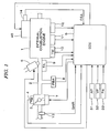
- FIG. 1 shows a configuration of an internal combustion engine and a control system therefor according to a first embodiment of the present invention
- FIG. 2 shows a configuration of a valve operating characteristic varying device shown in FIG. 1 ;
- FIGS. 3A and 3B illustrate a simplified configuration of the first valve operating characteristic varying mechanism shown in FIG. 2 ;
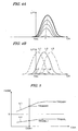
- FIGS. 4A and 4B show valve operating characteristics of an intake valve
- FIG. 5 shows a relationship between a rotational angle (CSA) of a control shaft of the first valve operating characteristic varying mechanism and a motor output torque (TRQM);
- CSA rotational angle
- TRQM motor output torque
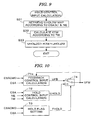
- FIG. 6 is a block diagram showing a configuration of a module which calculates an output control input (UFM) for determining a motor drive current;
- UFM output control input
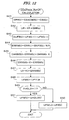
- FIG. 7 is a flowchart of a calculation process in the feedback control input calculation block of FIG. 6 ;
- FIG. 8 is a flowchart of a calculation process in the hold flag setting block of FIG. 6 ;
- FIG. 9 is a flowchart of a calculation process in the hold control input calculation block of FIG. 6 ;
- FIG. 10 is a block diagram showing a configuration of the output control input calculation module according to a second embodiment of the present invention.
- FIG. 11 is a block diagram showing a configuration of the feedback control input calculation block of FIG. 10 ;
- FIG. 12 is a flowchart of a calculation process in the feedback control input calculation block of FIG. 10 ;
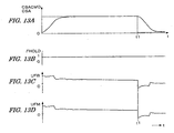
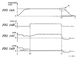
- FIGS.13A - 13D , 14A - 14D , and 15A - 15D are time charts for illustrating examples of control operations
- FIG. 16 is a block diagram showing a configuration of the output control input calculation module according to a third embodiment of the present invention.
- FIG. 17 is a block diagram showing a configuration of the feedback control input calculation block shown in FIG. 16 ;
- FIG. 18 is a block diagram showing a modification of the configuration shown in FIG. 16 ;
- FIG. 19 is a block diagram showing a configuration of the feedback control input calculation block shown in FIG. 18 ;
- FIG. 20 shows a configuration of a control system according to a fourth embodiment of the present invention.
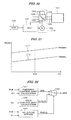
- FIG. 21 shows a relationship between a throttle valve opening (TH) and an output torque (TRQM) of a motor for actuating the throttle valve;
- FIG. 1 is a schematic diagram showing a configuration of an internal combustion engine and a control system therefor according to a first embodiment of the present invention
- FIG. 2 is a schematic diagram showing a configuration of a valve operating characteristic varying device.
- an internal combustion engine (hereinafter referred to as "engine") 1, having, for example, four cylinders, is provided with intake valves and exhaust valves, and cams for driving the intake valves and the exhaust valves.
- the engine 1 is provided with a valve operating characteristic varying device 40 having a first valve operating characteristic varying mechanism 41 and a second valve operating characteristic varying mechanism 42.
- the first valve operating characteristic varying mechanism 41 continuously varies the valve lift amount and the opening angle (valve opening period) of the intake valve.
- the second valve operating characteristic varying mechanism 42 is a cam phase varying mechanism for continuously varying the operating phases of the cams for driving the intake valves with reference to a rotational angle of the crank shaft of the engine 1.
- the second valve operating characteristic varying mechanism 42 varies the operating phase of the cam for driving each intake valve, and consequently varies the operating phase of each intake valve.
- the engine 1 has an intake pipe 2 provided with a throttle valve 3.
- a throttle valve opening (TH) sensor 4 is connected to the throttle valve 3, outputs an electrical signal corresponding to an opening of the throttle valve 3, and supplies the electrical signal to an electronic control unit (referred to as "ECU") 5.
- An actuator 7 for actuating the throttle valve 3 is connected to the throttle valve 3, and the operation of the actuator 7 is controlled by the ECU 5.
- Fuel injection valves 6 are inserted into the intake pipe 2 at locations between the cylinder block of the engine 1 and the throttle valve 3 and slightly upstream of the respective intake valves (not shown).
- the fuel injection valves 6 are connected to a fuel pump (not shown), and electrically connected to the ECU 5.
- a valve opening period of each fuel injection valve 6 is controlled by a signal output from the ECU 5.
- An intake pressure sensor 8 for detecting an intake pressure PBA and an intake air temperature sensor 9 for detecting an intake air temperature TA are disposed downstream of the throttle valve 3. Further, an engine coolant temperature sensor 10 for detecting an engine coolant temperature TW is mounted on the body of the engine 1. The detection signals from these sensors are supplied to the ECU 5.
- a crank angle position sensor 11 and a cam angle position sensor 12 are connected to the ECU 5.
- the crank angle position sensor 11 is provided to detect a rotational angle of the crankshaft (not shown) of the engine 1, and the cam angle position sensor 12 is provided to detect a rotational angle of a camshaft to which the cams for driving the intake valves of the engine 1 are fixed.
- a signal corresponding to the rotational angle detected by the crank angle sensor 11 and a signal corresponding to the rotational angle detected by the cam angle position sensor 12 are supplied to the ECU 5.
- the crank angle position sensor 11 generates one pulse (hereinafter referred to as "CRK pulse”) at every constant crank angle period (e.g., a period of 30 degrees) and a pulse for specifying a predetermined angle position of the crankshaft.
- CRK pulse one pulse
- the cam angle position sensor 12 generates a pulse at a predetermined crank angle position for a specific cylinder of the engine 1 (this pulse will be hereinafter referred to as "CYL pulse”).
- the cam angle position sensor 12 further generates a pulse at a top dead center (TDC) starting the intake stroke in each cylinder (this pulse will be hereinafter referred to as “TDC pulse”).
- TDC pulse top dead center
- These pulses are used to control the various timings such as a fuel injection timing and an ignition timing, as well as to detect an engine rotational speed NE.
- An actual operating phase CAIN of the crankshaft is detected based on the correlation between the TDC pulse output from the cam angle position sensor 12 and the CRK pulse output from the crank angle position sensor 11.
- An accelerator sensor 31, a vehicle speed sensor 32, and an atmospheric pressure sensor 33 are also connected to the ECU 5.
- the accelerator sensor 31 detects a depression amount AP of an accelerator pedal of the vehicle driven by the engine 1 (this depression amount will be hereinafter referred to as "accelerator operation amount").
- the vehicle speed sensor 32 detects a running speed (vehicle speed) VP of the vehicle.
- the atmospheric pressure sensor 33 detects an atmospheric pressure PA. The detection signals from these sensors are supplied to the ECU 5.
- the valve operating characteristic varying device 40 includes a first valve operating characteristic varying mechanism 41, a second valve operating characteristic varying mechanism 42, a motor 43, and an solenoid valve 44.
- the first valve operating characteristic varying mechanism 41 continuously varies a lift amount and an opening angle (hereinafter referred to simply as "lift amount LFT") of each intake valve.
- the second valve operating characteristic varying mechanism 42 continuously varies an operating phase of each intake valve.
- the motor 43 is provided for continuously changing the lift amount LFT of each intake valve.
- An opening of the solenoid valve 44 is continuously variable for changing the operating phase of each intake valve.
- the operating phase CAIN of the camshaft is used as a parameter indicative of the operating phase of the intake valve.
- a lubricating oil contained in an oil pan 46 is pressurized by an oil pump 45, and supplied to the solenoid valve 44. It is to be noted that a specific configuration of the second valve operating characteristic varying mechanism 42 is described, for example, in Japanese Patent Laid-open No. 2000-227013 .
- the sub-cam 53 has a roller 53a abutting the cam 52, and pivots around the shaft 53b by rotation of the camshaft 51.
- the rocker arm 54 has a roller 54a abutting the sub-cam 53. The movement of the sub-cam 53 is transmitted to the rocker arm 54 through the roller 54a.
- the control arm 55 has a roller 55b abutting the control cam 57, and pivots around the shaft 55a by rotation of the control shaft 56.
- the intake valve 60 maintains a substantially fully-closed state, since the movement of the sub-cam 53 is not substantially transmitted to the rocker arm 54.
- the movement of the sub-cam 53 is transmitted to the intake valve 60 through the rocker arm 54, and the intake valve 60 opens to a maximum lift amount LFTMAX (e.g., 12 mm).
- LFTMAX maximum lift amount
- the CPU in the ECU 5 controls an opening of the throttle valve 3, controls an amount of fuel to be supplied to the engine 1 (the opening period of each fuel injection valve 6), and controls the valve operating characteristic (intake air flow rate) through the motor 43 and the solenoid valve 44 according to the detected signals from the above-described sensors.
- a lift amount command value LFTCMD of the intake valve is calculated according to an engine operating condition, and a CS angle command value CSACMD is calculated according to the lift amount command value LFTCMD. Further, a feedback control of a drive current IMD of the motor 43 is performed so that the detected CS angle CSA coincides with the CS angle command value CSACMD.
- the power consumption can be reduced by setting the motor output torque TRQM to a value as smaller as possible.
- the fact that the maximum torque TRQMH and the minimum torque TRQML change due to characteristic variations of the valve operating characteristic varying mechanism 41 is taken into consideration, and the hold current value IDMHLD supplied to the motor 43 is set so as to obtain a hold torque substantially corresponding to an average value of the maximum torque TRQMH and the minimum torque TRQML.
- FIG. 6 is a block diagram showing a configuration of an output control input calculation module for calculating an output control input UFM which determines the drive current IMD supplied to the motor 43.
- the functions of the blocks which constitute the module are realized by the operation process executed by the CPU in the ECU 5.
- the output control input UFM corresponds to the control input to the controlled object.
- the output control input calculation module includes a feedback control input calculation block 71, a hold control input calculation block 72, a hold flag setting block 73, and a switching block 74.
- the feedback control input calculation block 71 calculates the feedback control input UFB so that the detected CS angle CSA coincides with the CS angle command value CSACMD. It is to be noted that the output of the control shaft rotational angle sensor 14 is subjected to a low pass filtering or an epsilon filtering, and the detection value, from which noise components are removed, is used as the CS angle CSA.
- the epsilon filtering is a known filtering method which effectively attenuates spike-like noises.
- the hold control input calculation block 72 calculates a hold control input UHOLD according to the CS angle CSA, the engine rotational speed NE, and the engine coolant temperature TW.
- the hold control input UHOLD is an control input corresponding to the hold current IDMHLD described above.
- the hold flag setting block 73 sets a hold flag FHOLD according to the CS angle command value CSACMD and the CS angle CSA.
- the switching block 74 selects the feedback control input UFB if the hold flag FHOLD is "0"; selects the hold control input UHOLD if the hold flag FHOLD is set to "1"; and outputs the selected control input as the output control input UFM.
- FIG. 7 is a flowchart of an control input calculation process for realizing the functions of the feedback control input calculation block 71 and the switching block 74 of FIG. 6 . This process is executed at predetermined time intervals TCAL (e.g., 2 milliseconds) by the CPU in the ECU 5.
- TCAL time intervals
- a control deviation ERR(k) is calculated by the following equation (1).
- "k” is a discrete time digitized with the execution period TCAL of this process.
- ERR k CSACMD k - CSA k
- FIG. 10 is a block diagram showing a configuration of an output control input calculation module according to a second embodiment of the present invention.
- the configuration shown in FIG. 10 is obtained by changing the feedback control input calculation block 71 shown in FIG. 6 to a feedback control input calculation block 71a.
- the output control input UFM is fed back to the feedback control input calculation block 71 a.
- the feedback control input calculation block 71 a corresponds to the feedback control means.
- the frequency shaping controller 104 calculates the feedback control input UFB so that the angular speed deviation DdCSA becomes "0" with the PI control (proportional and integral control).
- the transfer function H(s) corresponds to a transfer function of the PI (proportional and integral) control. Accordingly, the feedback control input UFB can be calculated by the same calculation as that in the feedback control input calculation block 71 in the first embodiment described above. That is, the angular speed deviation DdCSA in this embodiment corresponds to the control deviation ERR in the first embodiment. Therefore, by deleting step S11 in FIG. 7 , and replacing the control deviations ERR of steps S12 and S15 with the angular speed deviations DdCSA, the feedback control input UFB can be calculated.
- the electric power supplied to the motor 43 can be reduced by setting the hold control input UHOLD so that the drive current IMD of the motor 43 takes an average value of the upper limit value and the lower limit value of the required current for current for maintaining the CS angle at a constant value. Further, by making the feedback control input UFB coincide with the hold control input UHOLD when the output control input UFM is set to the hold control input UHOLD, good converging performance is obtained when the CS angle command value CSACMD changes, i.e., when the output control input UFM is switched from the hold control input UHOLD to the feedback control input UFB.
- FIG. 20 is a diagram showing a configuration of a throttle valve actuating device and a control system therefor according to a fourth embodiment of the present invention.
- the feedback control input calculation block 121 calculates the feedback control input UFB so that the detected throttle valve opening TH coincides with the target opening THR with the proportional and integral (PI) control.
- the feedback control input UFB is calculated by the calculation process obtained by replacing the CS angle command value CSACMD and the CS angle CSA in the process of FIG. 7 or FIG. 12 , respectively with the target opening THR and the throttle valve opening TH.
- a control input to said plant is set to the feedback control input when a control deviation between the controlled output and a target value is greater than a predetermined threshold value, and the control input is set to the hold control input when the control deviation is equal to or less than the predetermined threshold value.
- the feedback control input is made to gradually approach to or coincide with the hold control input when the control input is set to the hold control input.
Landscapes
- Engineering & Computer Science (AREA)
- Mechanical Engineering (AREA)
- General Engineering & Computer Science (AREA)
- Chemical & Material Sciences (AREA)
- Combustion & Propulsion (AREA)
- Output Control And Ontrol Of Special Type Engine (AREA)
- Feedback Control In General (AREA)
- Electrical Control Of Air Or Fuel Supplied To Internal-Combustion Engine (AREA)
- Combined Controls Of Internal Combustion Engines (AREA)
Abstract
Description
- The present invention relates to a control system for a plant, and particularly to a control system which controls a plant in a feedback manner so that a controlled output of the plant coincide with a target value, and performs a hold operation of a control input to the plant when a control deviation is comparatively small.
- Japanese Patent Laid-open No.
2005-30241 - Further, JP '241 describes a technique in which the integrated control input is output and electric power is supplied to an actuator even after the control deviation becomes "0".
- The control system shown in JP '241 is configured on the assumption that the controlled object has a torque transfer mechanism which permits a torque transfer from an output shaft of the actuator to the control shaft, but inhibits a torque transfer from the control shaft to the output shaft of the actuator. According to such a torque transfer mechanism, it is possible to stop supplying electric power to the actuator when the absolute value of the control deviation is equal to or less than the predetermined value. That is, if such a torque transfer mechanism is not adopted, it is necessary to supply electric power to the actuator in order to maintain the control deviation at "0".
- When supplying electric power to the actuator in order to maintain the control deviation at "0", there may be a case wherein the power to be supplied to the actuator can be set to a value within a predetermined allowable range, depending on the characteristic of the controlled object. For example, there is a case wherein the electric current to be supplied to the actuator which is necessary to start rotation of the control shaft from a stopped state, can be set to a value within the predetermined allowable range because of a great friction between the control shaft and other components in contact with the control shaft. In such case, it is preferable that the hold current supplied to the actuator for maintaining the control deviation at "0" is set to a value as small as possible. However, if the output of the feedback control device is changed so that the hold current becomes such a small value, a problem may be caused that a time period necessary for making the actual operating angle converge to the target operating angle becomes longer, when the target operating angle changes.
- The present invention was made contemplating the above-described points, and an object of the invention is to provide a control system for a plant, which can reduce a power consumption of the control actuator when the control deviation of the feedback control is comparatively small, and achieve good converging performance when the target value changes.
- To attain the above object, the present invention provides a control system for a plant, including feedback control means, hold control input calculating means, and control input setting means. The feedback control means calculates a feedback control input (UFB) so that a controlled output (CSA) of the plant coincides with a target value (CSACMD). The hold control input calculating means calculates a hold control input (UHOLD) according to an operating condition of the plant. The control input setting means sets a control input (UFM) to the plant to the feedback control input (UFB) when a control deviation (ERR) between the controlled output (CSA) and the target value (CSACMD) is greater than a predetermined threshold value (ERRHX), and sets the control input (UFM) to the hold control input (UHOLD) when the control deviation (ERR) is equal to or less than the predetermined threshold value (ERRHX). The feedback control means makes the feedback control input (UFB) gradually approach to or coincide with the hold control input (UHOLD) when the control input (UFM) is set to the hold control input (UHOLD).
- With this configuration, the hold control input is calculated according to the operating condition of the plant. When the control deviation between the controlled output and the target value is greater than the predetermined threshold value, the control input to the plant is set to the feedback control input. When the control deviation is equal to or less than the predetermined threshold value, the control input is set to the hold control input. When the control input is set to the hold control input, the feedback control input is set so as to gradually approach or coincide with the hold control input when the control input is set to the hold control input. For example, by setting the hold control input so that the power supply to the control actuator becomes comparatively small, the power consumption can be reduced. Further, by making the feedback control input gradually approach or coincide with the hold control input when the control input is set to the hold control input, good converging performance is obtained when the target value changes, i.e., when the control input is switched from the hold control input to the feedback control input.
- Preferably, the feedback control means calculates the feedback control input (UFB) using a proportional term (UP) and an integral term (UI) according to the control deviation (ERR), and calculates the integral term (UI) using a control input deviation (DUFB) which is a difference between the feedback control input (UFB) and the hold control input (UHOLD), when the control input (UFM) is set to the hold control input (UHOLD).
- With this configuration, the feedback control input is calculated using the proportional term and the integral term which are set according to the control deviation. When the control input is set to the hold control input, the integral term is calculated using the control input deviation, which is a difference between the feedback control input and the hold control input. According to this calculating method of the integral term, the feedback control input can be made to gradually approach the hold control input.
- Alternatively, the feedback control means sets the integral term (UI) so as to be proportional to a difference between the proportional term (UP) and the hold control input (UHOLD), when the control input (UFM) is set to the hold control input (UHOLD).
- With this configuration, the integral term is set to so as to be proportional to a difference between the proportional term and the hold control input when the control input is set to the hold control input. According to this calculating method of the integral term, the feedback control input can be immediately made to coincide with the hold control input (the feedback control input becomes equal to the hold control input).
- Preferably, the hold control input calculation means calculates the hold control input (UHOLD) according to a parameter (CSA) indicative of the controlled output of the plant.
- With this configuration, the hold control input is calculated according to the parameter indicative of the controlled output of the plant. The optimal hold control input changes depending on the controlled output of the plant or the target value of the controlled output. Therefore, by calculating the hold control input according to the controlled output of the plant or the target value of the controlled output, the hold control input which is optimal for reducing power consumption or coping with variation in the characteristic of the plant, can be obtained.
- Specifically, the plant is a valve operating characteristic varying mechanism (41) which continuously changes a lift amount of at least one intake valve of an internal combustion engine, and the valve operating characteristic varying mechanism (41) has a control shaft (56) for changing the lift amount and an actuator (43) for rotating the control shaft (56). A value (IDM) of an electric current supplied to the actuator (43) is calculated according to the control input (UFM), and the controlled output is a rotational angle (CSA) of the control shaft (56).
- In this configuration, the valve operating characteristic varying mechanism for continuously changing the lift amount of the intake valve of the internal combustion engine, is the controlled object. If the operating condition of the engine is constant, the lift amount of the intake valve is held at the same value. Therefore, in such operating condition, the value of the electric current supplied to the actuator for rotating the control shaft of the valve operating characteristic varying mechanism, can be reduced. Further, when the target value of the lift amount changes, the actual lift amount can be made to quickly converge to the target value.
-
FIG. 1 shows a configuration of an internal combustion engine and a control system therefor according to a first embodiment of the present invention; -
FIG. 2 shows a configuration of a valve operating characteristic varying device shown inFIG. 1 ; -
FIGS. 3A and 3B illustrate a simplified configuration of the first valve operating characteristic varying mechanism shown inFIG. 2 ; -
FIGS. 4A and 4B show valve operating characteristics of an intake valve; -
FIG. 5 shows a relationship between a rotational angle (CSA) of a control shaft of the first valve operating characteristic varying mechanism and a motor output torque (TRQM); -
FIG. 6 is a block diagram showing a configuration of a module which calculates an output control input (UFM) for determining a motor drive current; -
FIG. 7 is a flowchart of a calculation process in the feedback control input calculation block ofFIG. 6 ; -
FIG. 8 is a flowchart of a calculation process in the hold flag setting block ofFIG. 6 ; -
FIG. 9 is a flowchart of a calculation process in the hold control input calculation block ofFIG. 6 ; -
FIG. 10 is a block diagram showing a configuration of the output control input calculation module according to a second embodiment of the present invention; -
FIG. 11 is a block diagram showing a configuration of the feedback control input calculation block ofFIG. 10 ; -
FIG. 12 is a flowchart of a calculation process in the feedback control input calculation block ofFIG. 10 ; -
FIGS.13A - 13D ,14A - 14D , and15A - 15D are time charts for illustrating examples of control operations; -
FIG. 16 is a block diagram showing a configuration of the output control input calculation module according to a third embodiment of the present invention; -
FIG. 17 is a block diagram showing a configuration of the feedback control input calculation block shown inFIG. 16 ; -
FIG. 18 is a block diagram showing a modification of the configuration shown inFIG. 16 ; -
FIG. 19 is a block diagram showing a configuration of the feedback control input calculation block shown inFIG. 18 ; -
FIG. 20 shows a configuration of a control system according to a fourth embodiment of the present invention; -
FIG. 21 shows a relationship between a throttle valve opening (TH) and an output torque (TRQM) of a motor for actuating the throttle valve; and -
FIG. 22 is a block diagram showing a configuration of an output control input calculation module in the fourth embodiment. - Preferred embodiments of the present invention will now be described with reference to the drawings.
-
FIG. 1 is a schematic diagram showing a configuration of an internal combustion engine and a control system therefor according to a first embodiment of the present invention, andFIG. 2 is a schematic diagram showing a configuration of a valve operating characteristic varying device. Referring toFIG. 1 , an internal combustion engine (hereinafter referred to as "engine") 1, having, for example, four cylinders, is provided with intake valves and exhaust valves, and cams for driving the intake valves and the exhaust valves. Theengine 1 is provided with a valve operating characteristic varyingdevice 40 having a first valve operating characteristic varyingmechanism 41 and a second valve operating characteristic varyingmechanism 42. The first valve operating characteristic varyingmechanism 41 continuously varies the valve lift amount and the opening angle (valve opening period) of the intake valve. The second valve operating characteristic varyingmechanism 42 is a cam phase varying mechanism for continuously varying the operating phases of the cams for driving the intake valves with reference to a rotational angle of the crank shaft of theengine 1. The second valve operating characteristic varyingmechanism 42 varies the operating phase of the cam for driving each intake valve, and consequently varies the operating phase of each intake valve. - The
engine 1 has anintake pipe 2 provided with athrottle valve 3. A throttle valve opening (TH)sensor 4 is connected to thethrottle valve 3, outputs an electrical signal corresponding to an opening of thethrottle valve 3, and supplies the electrical signal to an electronic control unit (referred to as "ECU") 5. Anactuator 7 for actuating thethrottle valve 3 is connected to thethrottle valve 3, and the operation of theactuator 7 is controlled by theECU 5. -
Fuel injection valves 6 are inserted into theintake pipe 2 at locations between the cylinder block of theengine 1 and thethrottle valve 3 and slightly upstream of the respective intake valves (not shown). Thefuel injection valves 6 are connected to a fuel pump (not shown), and electrically connected to theECU 5. A valve opening period of eachfuel injection valve 6 is controlled by a signal output from theECU 5. - An
intake pressure sensor 8 for detecting an intake pressure PBA and an intake air temperature sensor 9 for detecting an intake air temperature TA are disposed downstream of thethrottle valve 3. Further, an enginecoolant temperature sensor 10 for detecting an engine coolant temperature TW is mounted on the body of theengine 1. The detection signals from these sensors are supplied to theECU 5. - A crank
angle position sensor 11 and a camangle position sensor 12 are connected to theECU 5. The crankangle position sensor 11 is provided to detect a rotational angle of the crankshaft (not shown) of theengine 1, and the camangle position sensor 12 is provided to detect a rotational angle of a camshaft to which the cams for driving the intake valves of theengine 1 are fixed. A signal corresponding to the rotational angle detected by thecrank angle sensor 11 and a signal corresponding to the rotational angle detected by the camangle position sensor 12 are supplied to theECU 5. The crankangle position sensor 11 generates one pulse (hereinafter referred to as "CRK pulse") at every constant crank angle period (e.g., a period of 30 degrees) and a pulse for specifying a predetermined angle position of the crankshaft. The camangle position sensor 12 generates a pulse at a predetermined crank angle position for a specific cylinder of the engine 1 (this pulse will be hereinafter referred to as "CYL pulse"). The camangle position sensor 12 further generates a pulse at a top dead center (TDC) starting the intake stroke in each cylinder (this pulse will be hereinafter referred to as "TDC pulse"). These pulses are used to control the various timings such as a fuel injection timing and an ignition timing, as well as to detect an engine rotational speed NE. An actual operating phase CAIN of the crankshaft is detected based on the correlation between the TDC pulse output from the camangle position sensor 12 and the CRK pulse output from the crankangle position sensor 11. - An
accelerator sensor 31, avehicle speed sensor 32, and anatmospheric pressure sensor 33 are also connected to theECU 5. Theaccelerator sensor 31 detects a depression amount AP of an accelerator pedal of the vehicle driven by the engine 1 (this depression amount will be hereinafter referred to as "accelerator operation amount"). Thevehicle speed sensor 32 detects a running speed (vehicle speed) VP of the vehicle. Theatmospheric pressure sensor 33 detects an atmospheric pressure PA. The detection signals from these sensors are supplied to theECU 5. - The valve operating characteristic varying
device 40, as shown inFIG. 2 , includes a first valve operating characteristic varyingmechanism 41, a second valve operating characteristic varyingmechanism 42, amotor 43, and ansolenoid valve 44. The first valve operating characteristic varyingmechanism 41 continuously varies a lift amount and an opening angle (hereinafter referred to simply as "lift amount LFT") of each intake valve. The second valve operating characteristic varyingmechanism 42 continuously varies an operating phase of each intake valve. Themotor 43 is provided for continuously changing the lift amount LFT of each intake valve. An opening of thesolenoid valve 44 is continuously variable for changing the operating phase of each intake valve. The operating phase CAIN of the camshaft is used as a parameter indicative of the operating phase of the intake valve. A lubricating oil contained in anoil pan 46 is pressurized by anoil pump 45, and supplied to thesolenoid valve 44. It is to be noted that a specific configuration of the second valve operating characteristic varyingmechanism 42 is described, for example, in Japanese Patent Laid-open No.2000-227013 - As shown in
FIG. 3A , the first valve operating characteristic varyingmechanism 41 includes acamshaft 51, acontrol arm 55, acontrol shaft 56, a sub-cam 53, and arocker arm 54. Thecamshaft 51 is provided with acam 52. Thecontrol arm 55 is supported by the cylinder head so that thecontrol arm 55 can pivot around ashaft 55a. Thecontrol shaft 56 is provided with acontrol cam 57 which pivots thecontrol arm 55. The sub-cam 53 is supported by thecontrol arm 55 through a supportingshaft 53b so that the sub-cam 53 can pivot around the supportingshaft 53b. The sub-cam 53 is actuated by thecam 52. Therocker arm 54 is actuated by the sub-cam 53 and drives (opens and closes) anintake valve 60. Therocker arm 54 is supported in thecontrol arm 55 so that therocker arm 54 can pivot. - The sub-cam 53 has a
roller 53a abutting thecam 52, and pivots around theshaft 53b by rotation of thecamshaft 51. Therocker arm 54 has aroller 54a abutting the sub-cam 53. The movement of the sub-cam 53 is transmitted to therocker arm 54 through theroller 54a. - The
control arm 55 has aroller 55b abutting thecontrol cam 57, and pivots around theshaft 55a by rotation of thecontrol shaft 56. In the state shown inFIG. 3A , theintake valve 60 maintains a substantially fully-closed state, since the movement of the sub-cam 53 is not substantially transmitted to therocker arm 54. On the other hand, in the state shown inFIG. 3B , the movement of the sub-cam 53 is transmitted to theintake valve 60 through therocker arm 54, and theintake valve 60 opens to a maximum lift amount LFTMAX (e.g., 12 mm). - Therefore, the lift amount LFT of the
intake valve 60 can be continuously varied by pivoting thecontrol shaft 56 with themotor 43. In this embodiment, the first valve operating characteristic varyingmechanism 41 includes a control shaftrotational angle sensor 14 for detecting a rotational angle (hereinafter referred to as "CS angle") CSA of thecontrol shaft 56. The detected CS angle CSA is used as a parameter indicative of the lift amount LFT. - It is to be noted that the detailed configuration of the first valve operating characteristic varying
mechanism 41 is described in the specification and drawings of the patent application (Japanese Patent Application No.2006-197254 - According to the first valve operating characteristic varying
mechanism 41, as shown inFIG. 4A , the lift amount LFT (and the opening angle) of the intake valve is varied. Further, according to the second valve operating characteristic varyingmechanism 42, the intake valve is driven with a phase from the most advanced phase, shown by the broken lines L1 and L2 inFIG. 4B to the most retarded phase, shown by the dot-and-dash lines L5 and L6 inFIG. 4B , depending on a change in the operating phase CAIN of the camshaft. InFIG. 4B , the characteristics shown by the solid lines L3 and L4 are the center of the variable phase range. - The
ECU 5 includes an input circuit having various functions including a function of shaping the waveforms of input signals from the various sensors, a function of correcting the voltage levels of the input signals to a predetermined level, and a function of converting analog signal values into digital signal values. The ECU5 further includes a central processing unit (hereinafter referred to as "CPU"), a memory circuit, and an output circuit. The memory circuit preliminarily stores various operating programs to be executed by the CPU and the results of computation or the like by the CPU. The output circuit supplies drive signals to theactuator 7, thefuel injection valves 6, themotor 43, and thesolenoid valve 44. - The CPU in the
ECU 5 controls an opening of thethrottle valve 3, controls an amount of fuel to be supplied to the engine 1 (the opening period of each fuel injection valve 6), and controls the valve operating characteristic (intake air flow rate) through themotor 43 and thesolenoid valve 44 according to the detected signals from the above-described sensors. - In the lift amount control (CS angle control) of the intake valve, a lift amount command value LFTCMD of the intake valve is calculated according to an engine operating condition, and a CS angle command value CSACMD is calculated according to the lift amount command value LFTCMD. Further, a feedback control of a drive current IMD of the
motor 43 is performed so that the detected CS angle CSA coincides with the CS angle command value CSACMD. -
FIG. 5 shows a relationship between the CS angle CSA and an output torque TRQM of the motor 43 (which is proportional to the drive current IMD). When the motor output torque TRQM is between a maximum torque TRQMH as shown by the solid line L1 and a minimum torque TRQML (negative value) shown by the solid line L2, the present CS angle CSA is maintained. For example, when the CS angle CSA is equal to an angle CSA1, and the motor output torques TRQM is equal to or less than a maximum torque TRQMH1 and equal to or greater than a minimum torques TRQML1, the CS angle CSA is maintained at the angle CSA1. In other words, the CS angle CSA increases if the motor output torque TRQM exceeds the maximum torque TRQMH1, while the CS angle CSA decreases if the motor output torque TRQM becomes less than the minimum torque TRQML1. - Therefore, when the CS angle command value CSACMD is unchanged, the power consumption can be reduced by setting the motor output torque TRQM to a value as smaller as possible. In this embodiment, the fact that the maximum torque TRQMH and the minimum torque TRQML change due to characteristic variations of the valve operating characteristic varying
mechanism 41 is taken into consideration, and the hold current value IDMHLD supplied to themotor 43 is set so as to obtain a hold torque substantially corresponding to an average value of the maximum torque TRQMH and the minimum torque TRQML. -
FIG. 6 is a block diagram showing a configuration of an output control input calculation module for calculating an output control input UFM which determines the drive current IMD supplied to themotor 43. The functions of the blocks which constitute the module are realized by the operation process executed by the CPU in theECU 5. The output control input UFM corresponds to the control input to the controlled object. - The output control input calculation module includes a feedback control
input calculation block 71, a hold controlinput calculation block 72, a holdflag setting block 73, and aswitching block 74. The feedback controlinput calculation block 71 calculates the feedback control input UFB so that the detected CS angle CSA coincides with the CS angle command value CSACMD. It is to be noted that the output of the control shaftrotational angle sensor 14 is subjected to a low pass filtering or an epsilon filtering, and the detection value, from which noise components are removed, is used as the CS angle CSA. The epsilon filtering is a known filtering method which effectively attenuates spike-like noises. - The hold control
input calculation block 72 calculates a hold control input UHOLD according to the CS angle CSA, the engine rotational speed NE, and the engine coolant temperature TW. The hold control input UHOLD is an control input corresponding to the hold current IDMHLD described above. - The hold
flag setting block 73 sets a hold flag FHOLD according to the CS angle command value CSACMD and the CS angle CSA. The switchingblock 74 selects the feedback control input UFB if the hold flag FHOLD is "0"; selects the hold control input UHOLD if the hold flag FHOLD is set to "1"; and outputs the selected control input as the output control input UFM. -
FIG. 7 is a flowchart of an control input calculation process for realizing the functions of the feedback controlinput calculation block 71 and the switchingblock 74 ofFIG. 6 . This process is executed at predetermined time intervals TCAL (e.g., 2 milliseconds) by the CPU in theECU 5. - In step S11, a control deviation ERR(k) is calculated by the following equation (1). In the equation (1), "k" is a discrete time digitized with the execution period TCAL of this process.

- In step S12, the control deviation ERR(k) and a proportional term gain KP are applied to the following equation (2), to calculate a proportional term UP.

- In step S13, it is determined whether or not the hold flag FHOLD is equal to "1". If FHOLD is equal to "0", a deviation integrated value ERRI(k) is calculated by the following equation (3).

- If FHOLD is equal to "1" in step S13, the deviation integrated value ERRI(k) is set by the following equation (4) (step S14). In the equation (4), "KI" is an integral term gain.

- In step S16, an integral term UI is calculated by the following equation (5).

- In step S17, the calculated proportional term UP and integral term UI are applied to the following equation (6), to calculate a feedback control input UFB. The output control input UFM is set to the feedback control input UFB (step S18).

- In step S19, the preceding value ERRI(k-1) of the deviation integrated value is set to the present value ERRI(k).
- By applying the deviation integrated value ERRI(k) calculated by the equation (4) to the equation (5), the integral term UI is obtained by the following equation (7). Therefore, by applying the integral term UI calculated by the equation (7) to the equation (6), the feedback control input UFB becomes equal to the hold control input UHOLD(k).

- According to the process of
FIG. 7 , when the hold flag FHOLD is equal to "0", the feedback control input UFB is set with the normal PI (proportional and integral) control, and the output control input UFM is similarly set. On the other hand, when the hold flag FHOLD is equal to "1", the feedback control input UFB coincides with the hold control input UHOLD(k), and the output control input UFM also coincides with the hold control input UHOLD(k). That is, the output control input UFM is set to the hold control input UHOLD(k). -
FIG. 8 is a flowchart of a hold flag setting process for realizing the function of the holdflag setting block 73 ofFIG. 6 . This process is executed at the predetermined time intervals TCAL by the CPU in theECU 5. - In step S20, the control deviation ERR (k) is calculated, like step S11 of
FIG. 7 . In step S21, it is determined whether or not the control deviation ERR(k) is equal to or less than a predetermined threshold value ERRHX. If the answer to step S21 is negative (NO), a counter CHLD is set to "0" (step S25), and the hold flag FHOLD is set to "0" (step S28). - In step S21, fi ERR(k) is equal to or less than ERRHX, a command value change amount DCSACMD, which indicates an amount of change in the CS angle command value CSACMD, is calculated by the following equation (8) (step S22).

- In step S23, it is determined whether or not the command value change amount DCSACMD is equal to "0". If the answer to step S23 is affirmative (YES), it is determined whether or not the CS angle CSA(k) is in a predetermined hold control range (step S24).
- The drive current IMD cannot be maintained at a constant value when the CS angle command value CSACMD is changing. Accordingly, if the answer to step S23 is negative (NO), the process proceeds to step S25 described above. Further, in this embodiment, even if the drive current IMD is made to be maintained at a constant value, there is an angular range in which the CS angle CSA cannot be maintained at a constant angle due to the torque applied to the
control shaft 56 from peripheral components other than themotor 43. Accordingly, the predetermined hold control range is set to a range other than such angular range. Therefore, when the CS angle CSA(k) is not in the predetermined hold control range, the process proceeds to step S25. - If the answer to step S24 is affirmative (YES), i.e., the CS angle command value CSACMD is constant and the CS angle CSA is in the predetermined hold control range, the counter CHLD is incremented by "1" (step S26), and it is determined whether or not the value of the counter CHLD is equal to or greater than a predetermined value N0 (e.g., "5") (step S27). While the answer to step S27 is negative (NO), the process proceeds to step S28. The answer to step S27 becomes affirmative (YES), the process proceeds to the above-described step S29, in which the hold flag FHOLD is set to"1".
-
FIG. 9 is a flowchart of a hold control input calculation process for realizing the function of the hold controlinput calculation block 72 ofFIG. 6 . This process is executed at the predetermined time intervals TCAL by the CPU in theECU 5. - In step S31, a UHOLDM map is retrieved according to the CS angle CSA(k) and the engine rotational speed NE, to calculate a hold control input map value UHOLDM. The UHOLDM map is set so that the hold control input map value UHOLDM increases as the CS angle CSA(k) increases. Further, since an optimal value of the hold control input changes depending on the engine rotational speeds NE, the hold control input map value UHOLDM is empirically set so as to take an optimal value, according to the engine rotational speed NE.
- In step S32, a KTW table is retrieved according to the engine coolant temperature TW, to calculate a correction coefficient KTW. The KTW table is set so that the correction coefficient KTW increase as the engine coolant temperature TW becomes higher.
- In step S33, the hold control input map value UHOLDM and the correction coefficient KTW are applied to the following equation (9), to calculate the hold control input UHOLD(k).

- As described above, in this embodiment, the hold control input UHOLD is calculated according to the CS angle CSA which is a controlled output. If the control deviation ERR is greater than the predetermined threshold value ERRHX, the output control input UFM, which is a control input to the controlled object, is set to the feedback control input UFB, while if the control deviation ERR is equal to or less than the predetermined threshold value ERRHX, the output control input UFM is set to the hold control input UHOLD. When the output control input UFM is set to the hold control input UHOLD, the feedback control input UFB is set so as to coincide with the hold control input UHOLD. In this embodiment, the hold control input UHOLD is set so that the drive current IMD of the
motor 43 becomes an average value of the upper limit value and the lower limit value of the required current for maintaining the CS angle at a constant value. Therefore, the electric power supplied to themotor 43 can be reduced. Further, by making the feedback control input UFB coincide with the hold control input UHOLD when the output control input UFM is set to the hold control input UHOLD, good converging performance is attained when the CS angle command value CSACMD changes, i.e., when the output control input UFM is switched to the feedback control input UFB from the hold control input UHOLD. - In this embodiment, the
ECU 5 constitutes the feedback control means, the hold control input calculating means, and the control input setting means. Specifically, the feedback controlinput calculation block 71 ofFIG. 6 corresponds to the feedback control means, and the hold controlinput calculation block 72 corresponds to the hold control input calculating means. Further, the holdflag setting block 73 and the switchingblock 74 correspond to the control input setting means. That is, steps S11, S12, S16, and S17 ofFIG. 7 correspond to the feedback control means, steps S13 to S15 and S18 ofFIG. 7 , and the process ofFIG. 8 correspond to the control input setting means, and the process ofFIG. 9 corresponds to the hold control input calculating means. -
FIG. 10 is a block diagram showing a configuration of an output control input calculation module according to a second embodiment of the present invention. The configuration shown inFIG. 10 is obtained by changing the feedback controlinput calculation block 71 shown inFIG. 6 to a feedback controlinput calculation block 71a. In this configuration, the output control input UFM is fed back to the feedback controlinput calculation block 71 a. -
FIG. 11 is a block diagram for illustrating the configuration of the feedback controlinput calculation block 71a shown inFIG. 10 . The feedback controlinput calculation block 71a includes multiplyingblocks blocks block 85, and anintegration block 83. This configuration is obtained by adding the subtracting blocks 82 and 87 and the multiplyingblock 88 to the feedback controlinput calculation block 72 which consists of the multiplyingblocks integration block 83, and the addingblock 85, and performs the normal PI control. - The subtracting
block 87 subtracts the output control input UFM from the feedback control input UFB, to calculate a control input deviation DUFB. The multiplyingblock 88 multiplies the reciprocal (1/KP) of the proportional term gain KP with the control input deviation DUFB. The subtractingblock 82 subtracts (DFUB/KP) from the control deviation ERR, to calculate a modified control deviation ERRM. Theintegration block 83 integrates the modified control deviation ERRM, to calculate a modified deviation integrated value ERRMI. The multiplyingblock 84 multiplies the integral term gain KI with the modified control deviation integrated value ERRMI, to calculate an integral term UI. The multiplyingblock 81 multiplies the proportional term gain KP to with the control deviation ERR, to calculate a proportional term UP. The addingblock 85 adds the proportional term UP and the integral term UI, to calculate the feedback control input UFB. - By expressing the feedback control input UFB using a transfer function of a continuous time system based on
FIG. 11 , the equations (10) and (11) are obtained. In the equation (10), "s" is the Laplace operator.

- By applying the feedback control input UFB expressed by the equation (10) to the equation (11), the following equation (12) is obtained.

- The transfer function in the equation (12) from the output control input UFM to the modified control deviation ERRM is a transfer function of high-pass filtering, and a steady-state gain of the transfer function is equal to "0". Therefore, if the output control input UFM is set to the hold control input UHOLD, the modified control deviation ERRM gradually approaches "0" regardless of the control deviation ERR, and the feedback control input UFB gradually approaches the hold control input UHOLD. It is to be noted that when UFM is equal to UFB, the modified control deviation ERRM becomes equal to the control deviation ERR, and the normal PI control operation is performed.
- As shown in
FIG. 11 , by adopting a configuration wherein the control deviation ERR is modified according to the control input deviation DUFB as a difference between the feedback control input UFB and the output control input UFM, to calculate the modified control deviation ERRM and the modified control deviation ERRM is input to theintegration block 83, the feedback control input UFB can be made to gradually approach the hold control input UHOD (i.e., the integral term UI can be prevented from being saturated) when the output control input UFM is set to the hold control input UHOLD. Consequently, the CS angle CSA can be quickly made to coincide with the CS angle command value CSACMD immediately after the hold flag FHOLD has changed from "1" to "0", i.e., immediately after restarting the normal feedback control operation. -
FIG. 12 is a flowchart of a process for realizing the function of the block diagram shown inFIG. 11 . This process is executed at the predetermined intervals TCAL by the CPU in theECU 5. - Steps S41 and S42 are respectively the same as steps S11 and S12 of
FIG. 7 , and the control deviation ERR(k) and the proportional term UP are calculated. - In step S43, the control input deviation DUFB(k) is calculated by the following equation (13).

- In step S44, the modified control deviation ERRM(k) is calculated by the following equation (14). In step S45, the modified control deviation ERRM(k) is integrated by the following equation (15), to calculate the modified deviation integrated value ERRMI(k).


- In step S46, the preceding value of the modified deviation integrated value ERRMI(k-1) is set to the present value ERRMI(k). In step S47, the integral term gain KI is multiplied with the modified deviation integrated value ERRMI(k), to calculate the integral term UI. In step S48, the proportional term UP and the integral term UI are added, to calculate the feedback control input UFB(k).
- In step S49, it is determined whether or not the hold flag FHOLD is equal to "1". IF FHOLD is equal to "0", the output control input UFM(k) is set to the feedback control input UFB(k) (step S50). On the other hand, if the hold flag FHOLD is equal to "1", the output control input UFM(k) is set to the hold control input UHOLD(k) (step S51).
- As described above, in this embodiment, when the output control input UFM is set to the hold control input UHOLD, the control input deviation DUFB which is a difference between the feedback control input UFB and the hold control input UHOLD is fed back to the integral term UI, and the feedback control input UFB is controlled so as to gradually approach the hold control input UHOLD. Therefore, the CS angle CSA as the controlled output can be made to quickly converge to the CS angle command value CSACMD, immediately after the CS angle command value CSACMD is changed, and the hold flag FHOLD is changed to "0".
- Next, an example of the above described control operation will be described with reference to
FIGS. 13A to 15D . InFIGS. 13A to 15D , changes in the CS angle command value CSACMD, the CS angle CSA, the hold flag FHOLD, the feedback control input UFB, and the output control input UFM are shown. InFIGS. 13A ,14A , and15A , the dashed line indicates the CS angle command value CSACMD, and the solid line indicates the CS angle CSA. -
FIGS. 13A to 13D show an example in which the hold operation of the output control input UFM is not performed when the CS angle command value CSACMD is constant (before time t1). The motor drive current IDM is approximately 20[A] corresponding to the output control input UFM, which means that the power consumption is comparatively great. -
FIGS. 14A to 14D shows an example in which the hold flag FHOLD is set to "1" at time t0, and the hold operation is started. In this example, the feedback control input calculation block continues the normal PI control in the hold operation (FHOLD = 1) and calculates the feedback control input UFB. On the other hand, the output control input UFM is set to the hold control input UHOLD (FIG. 14D ), thereby suppressing the motor drive current IDM to about 5[A]. However, the feedback control input UFB takes a value which is different from the output control input UFM (which is equal to the hold control input UHOLD) as shown inFIG. 14C , since the integral term UI becomes saturated. Consequently, a control delay occurrs (refer to the portion A ofFIG. 14A ) immediately after time t1 when the hold flag FHOLD is switched from "1" to "0". -
FIGS. 15A to 15D show an example in which the control of this embodiment is applied. After time t0 when the hold operation is started, the feedback control input UFB gradually approaches the output control input UFM (which is equal to the hold control input UHOLD), and the feedback control input coincides with the output control input UFM before time t1. Consequently, the control delay as shown inFIG. 14A does not occur immediately after time t1, and good converging characteristic is obtained. - In this embodiment, the feedback control
input calculation block 71 a corresponds to the feedback control means. -
FIG. 16 is a block diagram showing a configuration of an output control input calculation module according to a third embodiment of the present invention. The configuration shown inFIG. 16 is obtained by changing the feedback controlinput calculation block 71 of the configuration shown inFIG. 6 to a feedback controlinput calculation block 71b. - The feedback control
input calculation block 71 b includes, as shown inFIG. 17 , a slidingmode controller 101, adifferentiation block 102, a subtractingblock 103, and afrequency shaping controller 104. - The
differentiation block 102 differentiates the CS angle CSA, to calculate a rate of change in the CS angle CSA (hereinafter referred to as "CS angular speed") dCSA. The slidingmode controller 101 calculates a CS angular speed command value dCSACMD which is a target value of the CS angular speed dCSA so that the CS angle CSA coincides with the CS angle command value CSACMD by the sliding mode control. The subtractingblock 103 subtracts the CS angular speed dCSA from the CS angular speed command value dCSACMD, to calculate an angular speed deviation DdCSA. - The
frequency shaping controller 104 calculates the feedback control input UFB so that the angular speed deviation DdCSA becomes "0" with the PI control (proportional and integral control). - It is to be noted that the feedback control input UFB is output to the
motor 43 and the first valve operating characteristic varyingmechanism 41, which constitute a controlled object, through the switchingblock 74. However inFIG. 17 , a simplified configuration wherein the feedback control input UFB is directly input to the controlledobject 100 is shown. - In this embodiment, a block, which consists of the
differentiation block 102, the subtractingblock 103, thefrequency shaping controller 104, and the controlledobject 100, is defined as an extended controlledobject 110. A frequency shaping transfer function H(s), which is a transfer function of thefrequency shaping controller 104, is set so that a transfer function FX(s) of the extended controlledobject 110 coincide with a desired target transfer function F(s). - The transfer function FX(s) of the extended controlled
object 110 is given by the following equation (21). G(s) is a transfer function of the controlled object 100 (hereinafter referred to as "object transfer function"), and "s" is a transfer function of thedifferentiation block 102.
- The frequency shaping transfer function H(s), which makes the transfer function FX(s) coincide with the target transfer function F(s), is obtained as the following equation (22) by replacing FX(s) in the equation (21) with F(s) and solving the modified equation with respect to H(s).

- Next, how the target transfer function F(s) is set will be described. The object transfer function G(s), which is a transfer function of the first valve operating characteristic varying mechanism 41 (more properly, a transfer function of a controlled object model obtained by modeling the first valve operating characteristic varying mechanism 41) can be expressed with the following equation (23). In the equation (23), "J" and "B" are constants determined by the characteristics of the
motor 43 and the first valve operating characteristic varyingmechanism 41, for example, a motor torque constant, a gear reduction ratio, an inertia moment of themotor 43, an inertia moment of thecontrol shaft 56, and the like.
- In order to obtain the extended controlled
object 110 expressed by the similar transfer function even if there exist error factors such as a change in the dynamic characteristic of the controlled object and/or a great disturbance, the target transfer function F(s) is given, for example, by the following equation (24). Then, the frequency shaping transfer function H(s) is given by the following equation (25).

- The transfer function H(s) corresponds to a transfer function of the PI (proportional and integral) control. Accordingly, the feedback control input UFB can be calculated by the same calculation as that in the feedback control
input calculation block 71 in the first embodiment described above. That is, the angular speed deviation DdCSA in this embodiment corresponds to the control deviation ERR in the first embodiment. Therefore, by deleting step S11 inFIG. 7 , and replacing the control deviations ERR of steps S12 and S15 with the angular speed deviations DdCSA, the feedback control input UFB can be calculated. - Next, a calculation method of the CS angular speed command value dCSACMD in the sliding
mode controller 101 will be described. The CS angular speed command value dCSACMD is calculated as a sum of a equivalent control input UEQ and a reaching law control input URCH, as shown by the following equation (31).
- Further, by converting the transfer function F(s) of the extended controlled
object 110 to a corresponding transfer function of the discrete time system and expressing the CS angle CSA(k), which is the control output, using past values of the CS angle CSA and the CS angular speed command value dCSACMD which is the control input, the following equation (32) for defining the controlled object model is obtained.
- Further, a switching function value σ(k) is defined by the following equation (34) using a control deviation DCSA calculated by the equation (33).


- The equivalent control input UEQ is a control input which satisfies the following equation (35).

- By applying the equations (32), (33), and (34) to the equation (35), the following equation (36) for calculating the equivalent control input UEQ is obtained.


- Further, the reaching law control input URCH is calculated by the following equation (37).

- By configuring the control system as described above, a stable control can be performed by the sliding
mode controller 101 even if there exist error factors such as a change in the dynamic characteristic of the controlledobject 100, a great disturbance, and/or an influence of nonlinear elements. That is, the above error factors can be removed with the feedback control by the subtractingblock 103 and thefrequency shaping controller 104, thereby realizing a stable control by the slidingmode controller 101. Further, by performing the calculation in thefrequency shaping controller 104 similarly to the calculation in the feedback controlinput calculation block 71 of the first embodiment, an effect which is the same as that of the first embodiment, can be obtained. - That is, the electric power supplied to the
motor 43 can be reduced by setting the hold control input UHOLD so that the drive current IMD of themotor 43 takes an average value of the upper limit value and the lower limit value of the required current for current for maintaining the CS angle at a constant value. Further, by making the feedback control input UFB coincide with the hold control input UHOLD when the output control input UFM is set to the hold control input UHOLD, good converging performance is obtained when the CS angle command value CSACMD changes, i.e., when the output control input UFM is switched from the hold control input UHOLD to the feedback control input UFB. - In this embodiment, the feedback control
input calculation block 71 b corresponds to the feedback control means. That is, the slidingmode controller 101, the subtractingblock 103, thefrequency shaping controller 104, and thedifferentiation block 102 correspond to the feedback control means. - Alternatively, the
frequency shaping controller 104 may be changed to afrequency shaping controller 104a as shown inFIG. 18 , and thefrequency shaping controller 104a may be configured like the feedback controlinput calculation block 71a as shown inFIG. 19 . That is, by replacing the control deviation ERR with the angular speed deviation DdCSA and inputting the angular speed deviation DdCSA to the multiplyingblock 81 and the subtractingblock 82, the feedback control input UFB in the hold operation can be made to gradually approach the hold control input UHOLD. -
FIG. 20 is a diagram showing a configuration of a throttle valve actuating device and a control system therefor according to a fourth embodiment of the present invention. - A
throttle valve 103 is provided in anintake passage 102 of anengine 101. Areturn spring 104 for biasing the throttle valve .103 in the closing direction, and aresilient member 105 for biasing thethrottle valve 103 in the opening direction are mounted on thethrottle valve 103. Thethrottle valve 103 is configured so as to be actuated by amotor 106 via a gear mechanism (not shown). Thethrottle valve 103, thereturn spring 104, theresilient member 105, themotor 106, and the gear mechanism (not shown) constitute the throttlevalve actuating device 110 which is a controlled object. - The
motor 106 is connected to anECU 107 and the operation is controlled by theECU 107. Thethrottle valve 103 is provided a throttlevalve opening sensor 108 for detecting a throttle valve opening TH, and the detection signal is supplied to theECU 107. - The
ECU 107 is connected to anaccelerator sensor 109 for detecting a depression amount ACC of an accelerator pedal indicative of an demand output of the driver of the vehicle on which theengine 101 is mounted. The detection signal of theaccelerator sensor 109 is supplied to theECU 7. - The
ECU 107 includes an input circuit, a CPU, a memory circuit, an output circuit, and the like, similarly to theECU 5 in the first embodiment. TheECU 107 calculates a target opening THR of thethrottle valve 103 according to the depression amount ACC of the accelerator pedal, and calculates a control input UFM to themotor 106 so that the detected throttle valve opening TH coincides with the target opening THR. TheECU 107 supplies an electrical signal according to the control input UFM, specifically, a pulse-width modulation (PWM) signal of a duty ratio proportional to the control input UFM to themotor 106. -
FIG. 21 shows a relationship between the opening TH of thethrottle valve 103 and an output torque TRQM of themotor 106. That is, when the throttle valve opening TH is equal to the opening TH1, the throttle valve opening TH increases if the output torque TRQM exceeds the maximum torque TRQMH shown by the solid line L11; the throttle valve opening TH decreases if the output torque TRQM becomes less than the minimum torque TRQML shown by the solid line L12; and the throttle valve opening TH is maintained at the opening TH1 if the output torque TRQM is between the maximum torque TRQMH and the minimum torque TRQML. Therefore, when the target opening THR is constant, the power consumption can be reduced by appropriately setting the hold control input UHOLD for reducing the duty ratio of the PWM signal, like the first embodiment. -
FIG. 22 is a block diagram showing a configuration of an output control input calculation module in this embodiment. This module is configured similarly to that in the first embodiment, and includes a feedback controlinput calculation block 121, a hold controlinput calculation block 122, a holdflag setting block 123, and a switching block 124: - The feedback control
input calculation block 121 calculates the feedback control input UFB so that the detected throttle valve opening TH coincides with the target opening THR with the proportional and integral (PI) control. Specifically, the feedback control input UFB is calculated by the calculation process obtained by replacing the CS angle command value CSACMD and the CS angle CSA in the process ofFIG. 7 orFIG. 12 , respectively with the target opening THR and the throttle valve opening TH. - The hold control
input calculation block 122 calculates the hold control input UHOLD according to the throttle valve opening TH. The hold control input UHOLD is set, for example, to a value corresponding to the average value of the maximum torque TRQMH and the minimum torque TRQML, like the first embodiment. Therefore, the hold control input UHOLD is set so as to increase as the throttle valve opening TH increases. - The hold
flag setting block 123 sets the hold flag FHOLD according to the target opening THR and the throttle valve opening TH by the process similar to the process shown inFIG. 8 . Theswitching block 124 selects the feedback control input UFB when the hold flag FHOLD is equal to "0; selects the hold control input UHOLD when the hold flag FHOLD is set to "1"; and outputs the selected control input as the output control input UFM. - By configuring the output control input calculation module as described above, the same effect as the first embodiment or the second embodiment is obtained.
- In this embodiment, the feedback control
input calculation block 121 corresponds to the feedback control means, the hold controlinput calculation block 122 corresponds to the hold control input calculating means, and the holdflag setting block 123 and theswitching block 124 correspond to the control input setting means. - The present invention is not limited to the embodiments described above, and is applicable also to various controls, particularly to a positioning control of a controlled object including an element with large friction. For example, the present invention is applicable to a positioning device using a ball screw (for example, used in a machine tool or the like), a valve timing varying device using an electromagnetic clutch, a shift fork positioning device of an automatic transmission, and the like.
- Further, in the first to third embodiments described above, the hold control input UHOLD applied during the hold operation is set so that the drive current IMD of the
motor 43 is set to an average value of the upper limit value and the lower limit value of the current required for holding. Alternatively, the drive current IMD may be set to a value which greater than the minimum current value and less than the average value. By such setting of the drive currrent, the power consumption of themotor 43 can be further reduced. - The present invention may be embodied in other specific forms without departing from the spirit or essential characteristics thereof. The presently disclosed embodiments are therefore to be considered in all respects as illustrative and not restrictive, the scope of the invention being indicated by the appended claims, rather than the foregoing description, and all changes which come within the meaning and range of equivalency of the claims are, therefore, to be embraced therein.
A control system for a plant is disclosed. In the control system, a feedback control input is calculated so that a controlled output of said plant coincides with a target value. A hold control input is calculated according to an operating condition of said plant. A control input to said plant is set to the feedback control input when a control deviation between the controlled output and a target value is greater than a predetermined threshold value, and the control input is set to the hold control input when the control deviation is equal to or less than the predetermined threshold value. The feedback control input is made to gradually approach to or coincide with the hold control input when the control input is set to the hold control input.
Claims (10)
- A control system for a plant, comprising:feedback control means for calculating a feedback control input so that a controlled output of said plant coincides with a target value;hold control input calculating means for calculating a hold control input according to an operating condition of said plant; andcontrol input setting means for setting a control input to said plant to the feedback control input when a control deviation between the controlled output and the target value is greater than a predetermined threshold value, and setting the control input to the hold control input when the control deviation is equal to or less than the predetermined threshold value,wherein the feedback control means makes the feedback control input gradually approach to or coincide with the hold control input when the control input is set to the hold control input:
- A control system according to claim 1, wherein the feedback control means calculates the feedback control input using a proportional term and an integral term according to the control deviation, and calculates the integral term using a control input deviation which is a difference between the feedback control input and the hold control input, when the control input is set to the hold control input.
- A control system according to claim 1, wherein the feedback control means calculates the feedback control input using a proportional term and an integral term according to the control deviation, and sets the integral term so as to be proportional to a difference between the proportional term and the hold control input, when the control input is set to the hold control input.
- A control system according to claim 1, wherein the hold control input calculation means calculates the hold control input according to a parameter indicative of the controlled output of said plant.
- A control system according to claim 1, wherein said plant is a valve operating characteristic varying mechanism which continuously changes a lift amount of at least one intake valve of an internal combustion engine, and the valve operating characteristic varying mechanism has a control shaft for changing the lift amount and an actuator for rotating the control shaft,
wherein a value of an electric current supplied to said actuator is calculated according to the control input, and the controlled output is a rotational angle of the control shaft. - A control method for a plant, comprising the steps of:a) calculating a feedback control input so that a controlled output of said plant coincides with a target value;b) calculating a hold control input according to an operating condition of said plant; andc) setting a control input to said plant to the feedback control input when a control deviation between the controlled output and the target value is greater than a predetermined threshold value, and setting the control input to the hold control input when the control deviation is equal to or less than the predetermined threshold value,wherein the feedback control input is made to gradually approach to or coincide with the hold control input when the control input is set to the hold control input.
- A control method according to claim 6, wherein the feedback control input is calculated using a proportional term and an integral term according to the control deviation, and the integral term is calculated using a control input deviation which is a difference between the feedback control input and the hold control input, when the control input is set to the hold control input.
- A control method according to claim 6, wherein the feedback control input is calculated using a proportional term and an integral term according to the control deviation, and the integral term is set so as to be proportional to a difference between the proportional term and the hold control input, when the control input is set to the hold control input.
- A control method according to claim 6, wherein the hold control input is calculated according to a parameter indicative of the controlled output of said plant.
- A control method according to claim 6, wherein said plant is a valve operating characteristic varying mechanism which continuously changes a lift amount of at least one intake valve of an internal combustion engine, and the valve operating characteristic varying mechanism has a control shaft for changing the lift amount and an actuator for rotating the control shaft,
wherein a value of an electric current supplied to said actuator is calculated according to the control input, and the controlled output is a rotational angle of the control shaft.
Applications Claiming Priority (1)
| Application Number | Priority Date | Filing Date | Title |
|---|---|---|---|
| JP2007202467A JP4571962B2 (en) | 2007-08-03 | 2007-08-03 | Plant control equipment |
Publications (2)
| Publication Number | Publication Date |
|---|---|
| EP2025905A1 true EP2025905A1 (en) | 2009-02-18 |
| EP2025905B1 EP2025905B1 (en) | 2014-02-19 |
Family
ID=39855051
Family Applications (1)
| Application Number | Title | Priority Date | Filing Date |
|---|---|---|---|
| EP08012542.0A Ceased EP2025905B1 (en) | 2007-08-03 | 2008-07-10 | Control system for a variable valve train of an internal combustion engine |
Country Status (3)
| Country | Link |
|---|---|
| US (1) | US7921832B2 (en) |
| EP (1) | EP2025905B1 (en) |
| JP (1) | JP4571962B2 (en) |
Cited By (3)
| Publication number | Priority date | Publication date | Assignee | Title |
|---|---|---|---|---|
| TWI471708B (en) * | 2010-04-26 | 2015-02-01 | Mitsubishi Electric Corp | Servo control apparatus |
| EP3236028A1 (en) * | 2016-01-29 | 2017-10-25 | Otics Corporation | Variable valve mechanism of internal combustion engine |
| CN113075879A (en) * | 2020-01-03 | 2021-07-06 | 中国科学院沈阳自动化研究所 | Engine control system of tilt rotor unmanned aerial vehicle |
Families Citing this family (2)
| Publication number | Priority date | Publication date | Assignee | Title |
|---|---|---|---|---|
| JP5287912B2 (en) * | 2011-03-15 | 2013-09-11 | 株式会社デンソー | Engine control device |
| CN104515887B (en) * | 2013-09-29 | 2018-11-09 | 联创汽车电子有限公司 | HIL rack high pressure MeUn valve current acquisition methods |
Citations (4)
| Publication number | Priority date | Publication date | Assignee | Title |
|---|---|---|---|---|
| DE4316857A1 (en) | 1992-05-19 | 1993-12-02 | Nippon Denso Co | Lean-burn control system for an internal combustion engine |
| DE19618932A1 (en) | 1996-05-10 | 1997-11-20 | Siemens Ag | Device and method for regulating the fuel in a high pressure accumulator |
| EP1203874A1 (en) | 1999-07-28 | 2002-05-08 | Hitachi, Ltd. | Method and apparatus for motor-driven throttle valve, automobile, method of measuring temperature of motor for driving automotive throttle valve, and method of measuring motor temperature |
| JP2005030241A (en) | 2003-07-09 | 2005-02-03 | Hitachi Unisia Automotive Ltd | Control device for variable valve mechanism |
Family Cites Families (7)
| Publication number | Priority date | Publication date | Assignee | Title |
|---|---|---|---|---|
| US6666793B2 (en) * | 2001-02-22 | 2003-12-23 | Nissan Motor Co., Ltd. | Control of infinitely variable transmission |
| JP4161789B2 (en) * | 2003-04-25 | 2008-10-08 | いすゞ自動車株式会社 | Fuel injection control device |
| DE102004026157B4 (en) * | 2003-05-30 | 2017-11-09 | Honda Motor Co., Ltd. | Valve timing control system and control system for an internal combustion engine |
| JP4188158B2 (en) * | 2003-07-03 | 2008-11-26 | 本田技研工業株式会社 | Control device for internal combustion engine |
| JP4082596B2 (en) * | 2003-07-07 | 2008-04-30 | 本田技研工業株式会社 | Control device |
| US7251638B2 (en) * | 2004-03-03 | 2007-07-31 | Yamaha Hatsudoki Kabushiki Kaisha | Intelligent robust control system for motorcycle using soft computing optimizer |
| JP4806987B2 (en) * | 2005-07-25 | 2011-11-02 | トヨタ自動車株式会社 | Control device for internal combustion engine |
-
2007
- 2007-08-03 JP JP2007202467A patent/JP4571962B2/en not_active Expired - Fee Related
-
2008
- 2008-07-10 EP EP08012542.0A patent/EP2025905B1/en not_active Ceased
- 2008-07-15 US US12/219,043 patent/US7921832B2/en not_active Expired - Fee Related
Patent Citations (4)
| Publication number | Priority date | Publication date | Assignee | Title |
|---|---|---|---|---|
| DE4316857A1 (en) | 1992-05-19 | 1993-12-02 | Nippon Denso Co | Lean-burn control system for an internal combustion engine |
| DE19618932A1 (en) | 1996-05-10 | 1997-11-20 | Siemens Ag | Device and method for regulating the fuel in a high pressure accumulator |
| EP1203874A1 (en) | 1999-07-28 | 2002-05-08 | Hitachi, Ltd. | Method and apparatus for motor-driven throttle valve, automobile, method of measuring temperature of motor for driving automotive throttle valve, and method of measuring motor temperature |
| JP2005030241A (en) | 2003-07-09 | 2005-02-03 | Hitachi Unisia Automotive Ltd | Control device for variable valve mechanism |
Cited By (5)
| Publication number | Priority date | Publication date | Assignee | Title |
|---|---|---|---|---|
| TWI471708B (en) * | 2010-04-26 | 2015-02-01 | Mitsubishi Electric Corp | Servo control apparatus |
| EP3236028A1 (en) * | 2016-01-29 | 2017-10-25 | Otics Corporation | Variable valve mechanism of internal combustion engine |
| US10233790B2 (en) | 2016-01-29 | 2019-03-19 | Otics Corporation | Variable valve mechanism of internal combustion engine |
| CN113075879A (en) * | 2020-01-03 | 2021-07-06 | 中国科学院沈阳自动化研究所 | Engine control system of tilt rotor unmanned aerial vehicle |
| CN113075879B (en) * | 2020-01-03 | 2022-02-01 | 中国科学院沈阳自动化研究所 | Engine control system of tilt rotor unmanned aerial vehicle |
Also Published As
| Publication number | Publication date |
|---|---|
| JP4571962B2 (en) | 2010-10-27 |
| JP2009036141A (en) | 2009-02-19 |
| EP2025905B1 (en) | 2014-02-19 |
| US7921832B2 (en) | 2011-04-12 |
| US20090037074A1 (en) | 2009-02-05 |
Similar Documents
| Publication | Publication Date | Title |
|---|---|---|
| US20100139601A1 (en) | Control system for internal combustion engine | |
| EP2025905B1 (en) | Control system for a variable valve train of an internal combustion engine | |
| US20030094151A1 (en) | Cam phase control apparatus and method, and engine control unit for internal combustion engine | |
| US7770558B2 (en) | Intake air control system for internal combustion engine | |
| EP2189638B1 (en) | Control system for plant | |
| EP2189632B1 (en) | Control system for internal combustion engine | |
| JP4830998B2 (en) | Valve characteristic control device and valve characteristic control system | |
| EP1686437B1 (en) | Controller | |
| EP2258935B1 (en) | Device for detecting deterioration in response of control subject | |
| US7826956B2 (en) | Control system for plant | |
| US6874469B2 (en) | Control system for internal combustion engine | |
| JP5752960B2 (en) | Control device for electromagnetic variable valve timing device | |
| JP5306156B2 (en) | Intake control device for internal combustion engine | |
| JP4760423B2 (en) | Oil deterioration judgment device for internal combustion engine | |
| JP4379273B2 (en) | Internal combustion engine with variable compression ratio mechanism | |
| JP5182388B2 (en) | Valve characteristic control device and valve characteristic control system | |
| JP3918219B2 (en) | Valve timing control device for internal combustion engine | |
| JP5411717B2 (en) | Intake control device for internal combustion engine | |
| JP2007064022A (en) | Control device | |
| JP2009085148A (en) | Control device for variable valve mechanism | |
| JP2006200401A (en) | Control device for variable valve mechanism |
Legal Events
| Date | Code | Title | Description |
|---|---|---|---|
| PUAI | Public reference made under article 153(3) epc to a published international application that has entered the european phase |
Free format text: ORIGINAL CODE: 0009012 |
|
| 17P | Request for examination filed |
Effective date: 20080710 |
|
| AK | Designated contracting states |
Kind code of ref document: A1 Designated state(s): AT BE BG CH CY CZ DE DK EE ES FI FR GB GR HR HU IE IS IT LI LT LU LV MC MT NL NO PL PT RO SE SI SK TR |
|
| AX | Request for extension of the european patent |
Extension state: AL BA MK RS |
|
| AKX | Designation fees paid |
Designated state(s): DE GB |
|
| GRAP | Despatch of communication of intention to grant a patent |
Free format text: ORIGINAL CODE: EPIDOSNIGR1 |
|
| INTG | Intention to grant announced |
Effective date: 20130930 |
|
| GRAS | Grant fee paid |
Free format text: ORIGINAL CODE: EPIDOSNIGR3 |
|
| GRAA | (expected) grant |
Free format text: ORIGINAL CODE: 0009210 |
|
| RIN1 | Information on inventor provided before grant (corrected) |
Inventor name: IDE, HIROHITO |
|
| AK | Designated contracting states |
Kind code of ref document: B1 Designated state(s): DE GB |
|
| RAP1 | Party data changed (applicant data changed or rights of an application transferred) |
Owner name: HONDA MOTOR CO., LTD. |
|
| REG | Reference to a national code |
Ref country code: GB Ref legal event code: FG4D |
|
| REG | Reference to a national code |
Ref country code: DE Ref legal event code: R096 Ref document number: 602008030335 Country of ref document: DE Effective date: 20140403 |
|
| REG | Reference to a national code |
Ref country code: DE Ref legal event code: R097 Ref document number: 602008030335 Country of ref document: DE |
|
| PLBE | No opposition filed within time limit |
Free format text: ORIGINAL CODE: 0009261 |
|
| STAA | Information on the status of an ep patent application or granted ep patent |
Free format text: STATUS: NO OPPOSITION FILED WITHIN TIME LIMIT |
|
| 26N | No opposition filed |
Effective date: 20141120 |
|
| REG | Reference to a national code |
Ref country code: DE Ref legal event code: R097 Ref document number: 602008030335 Country of ref document: DE Effective date: 20141120 |
|
| GBPC | Gb: european patent ceased through non-payment of renewal fee |
Effective date: 20140710 |
|
| REG | Reference to a national code |
Ref country code: DE Ref legal event code: R084 Ref document number: 602008030335 Country of ref document: DE |
|
| PG25 | Lapsed in a contracting state [announced via postgrant information from national office to epo] |
Ref country code: GB Free format text: LAPSE BECAUSE OF NON-PAYMENT OF DUE FEES Effective date: 20140710 |
|
| REG | Reference to a national code |
Ref country code: DE Ref legal event code: R084 Ref document number: 602008030335 Country of ref document: DE Effective date: 20150505 |
|
| PGFP | Annual fee paid to national office [announced via postgrant information from national office to epo] |
Ref country code: DE Payment date: 20150707 Year of fee payment: 8 |
|
| REG | Reference to a national code |
Ref country code: DE Ref legal event code: R119 Ref document number: 602008030335 Country of ref document: DE |
|
| PG25 | Lapsed in a contracting state [announced via postgrant information from national office to epo] |
Ref country code: DE Free format text: LAPSE BECAUSE OF NON-PAYMENT OF DUE FEES Effective date: 20170201 |