EP2025892A1 - Electric supercharger - Google Patents
Electric supercharger Download PDFInfo
- Publication number
- EP2025892A1 EP2025892A1 EP07742382A EP07742382A EP2025892A1 EP 2025892 A1 EP2025892 A1 EP 2025892A1 EP 07742382 A EP07742382 A EP 07742382A EP 07742382 A EP07742382 A EP 07742382A EP 2025892 A1 EP2025892 A1 EP 2025892A1
- Authority
- EP
- European Patent Office
- Prior art keywords
- turbine
- thrust bearing
- thrust
- motor
- compressor
- Prior art date
- Legal status (The legal status is an assumption and is not a legal conclusion. Google has not performed a legal analysis and makes no representation as to the accuracy of the status listed.)
- Granted
Links
Images


Classifications
-
- F—MECHANICAL ENGINEERING; LIGHTING; HEATING; WEAPONS; BLASTING
- F02—COMBUSTION ENGINES; HOT-GAS OR COMBUSTION-PRODUCT ENGINE PLANTS
- F02B—INTERNAL-COMBUSTION PISTON ENGINES; COMBUSTION ENGINES IN GENERAL
- F02B37/00—Engines characterised by provision of pumps driven at least for part of the time by exhaust
- F02B37/04—Engines with exhaust drive and other drive of pumps, e.g. with exhaust-driven pump and mechanically-driven second pump
- F02B37/10—Engines with exhaust drive and other drive of pumps, e.g. with exhaust-driven pump and mechanically-driven second pump at least one pump being alternatively or simultaneously driven by exhaust and other drive, e.g. by pressurised fluid from a reservoir or an engine-driven pump
-
- F—MECHANICAL ENGINEERING; LIGHTING; HEATING; WEAPONS; BLASTING
- F01—MACHINES OR ENGINES IN GENERAL; ENGINE PLANTS IN GENERAL; STEAM ENGINES
- F01D—NON-POSITIVE DISPLACEMENT MACHINES OR ENGINES, e.g. STEAM TURBINES
- F01D25/00—Component parts, details, or accessories, not provided for in, or of interest apart from, other groups
- F01D25/16—Arrangement of bearings; Supporting or mounting bearings in casings
- F01D25/166—Sliding contact bearing
- F01D25/168—Sliding contact bearing for axial load mainly
-
- F—MECHANICAL ENGINEERING; LIGHTING; HEATING; WEAPONS; BLASTING
- F02—COMBUSTION ENGINES; HOT-GAS OR COMBUSTION-PRODUCT ENGINE PLANTS
- F02B—INTERNAL-COMBUSTION PISTON ENGINES; COMBUSTION ENGINES IN GENERAL
- F02B39/00—Component parts, details, or accessories relating to, driven charging or scavenging pumps, not provided for in groups F02B33/00 - F02B37/00
-
- F—MECHANICAL ENGINEERING; LIGHTING; HEATING; WEAPONS; BLASTING
- F02—COMBUSTION ENGINES; HOT-GAS OR COMBUSTION-PRODUCT ENGINE PLANTS
- F02B—INTERNAL-COMBUSTION PISTON ENGINES; COMBUSTION ENGINES IN GENERAL
- F02B39/00—Component parts, details, or accessories relating to, driven charging or scavenging pumps, not provided for in groups F02B33/00 - F02B37/00
- F02B39/02—Drives of pumps; Varying pump drive gear ratio
- F02B39/08—Non-mechanical drives, e.g. fluid drives having variable gear ratio
- F02B39/10—Non-mechanical drives, e.g. fluid drives having variable gear ratio electric
-
- F—MECHANICAL ENGINEERING; LIGHTING; HEATING; WEAPONS; BLASTING
- F02—COMBUSTION ENGINES; HOT-GAS OR COMBUSTION-PRODUCT ENGINE PLANTS
- F02B—INTERNAL-COMBUSTION PISTON ENGINES; COMBUSTION ENGINES IN GENERAL
- F02B39/00—Component parts, details, or accessories relating to, driven charging or scavenging pumps, not provided for in groups F02B33/00 - F02B37/00
- F02B39/14—Lubrication of pumps; Safety measures therefor
-
- F—MECHANICAL ENGINEERING; LIGHTING; HEATING; WEAPONS; BLASTING
- F02—COMBUSTION ENGINES; HOT-GAS OR COMBUSTION-PRODUCT ENGINE PLANTS
- F02C—GAS-TURBINE PLANTS; AIR INTAKES FOR JET-PROPULSION PLANTS; CONTROLLING FUEL SUPPLY IN AIR-BREATHING JET-PROPULSION PLANTS
- F02C6/00—Plural gas-turbine plants; Combinations of gas-turbine plants with other apparatus; Adaptations of gas-turbine plants for special use
- F02C6/04—Gas-turbine plants providing heated or pressurised working fluid for other apparatus, e.g. without mechanical power output
- F02C6/10—Gas-turbine plants providing heated or pressurised working fluid for other apparatus, e.g. without mechanical power output supplying working fluid to a user, e.g. a chemical process, which returns working fluid to a turbine of the plant
- F02C6/12—Turbochargers, i.e. plants for augmenting mechanical power output of internal-combustion piston engines by increase of charge pressure
-
- F—MECHANICAL ENGINEERING; LIGHTING; HEATING; WEAPONS; BLASTING
- F05—INDEXING SCHEMES RELATING TO ENGINES OR PUMPS IN VARIOUS SUBCLASSES OF CLASSES F01-F04
- F05D—INDEXING SCHEME FOR ASPECTS RELATING TO NON-POSITIVE-DISPLACEMENT MACHINES OR ENGINES, GAS-TURBINES OR JET-PROPULSION PLANTS
- F05D2220/00—Application
- F05D2220/40—Application in turbochargers
-
- F—MECHANICAL ENGINEERING; LIGHTING; HEATING; WEAPONS; BLASTING
- F05—INDEXING SCHEMES RELATING TO ENGINES OR PUMPS IN VARIOUS SUBCLASSES OF CLASSES F01-F04
- F05D—INDEXING SCHEME FOR ASPECTS RELATING TO NON-POSITIVE-DISPLACEMENT MACHINES OR ENGINES, GAS-TURBINES OR JET-PROPULSION PLANTS
- F05D2220/00—Application
- F05D2220/70—Application in combination with
- F05D2220/76—Application in combination with an electrical generator
-
- F—MECHANICAL ENGINEERING; LIGHTING; HEATING; WEAPONS; BLASTING
- F05—INDEXING SCHEMES RELATING TO ENGINES OR PUMPS IN VARIOUS SUBCLASSES OF CLASSES F01-F04
- F05D—INDEXING SCHEME FOR ASPECTS RELATING TO NON-POSITIVE-DISPLACEMENT MACHINES OR ENGINES, GAS-TURBINES OR JET-PROPULSION PLANTS
- F05D2240/00—Components
- F05D2240/50—Bearings
- F05D2240/52—Axial thrust bearings
-
- Y—GENERAL TAGGING OF NEW TECHNOLOGICAL DEVELOPMENTS; GENERAL TAGGING OF CROSS-SECTIONAL TECHNOLOGIES SPANNING OVER SEVERAL SECTIONS OF THE IPC; TECHNICAL SUBJECTS COVERED BY FORMER USPC CROSS-REFERENCE ART COLLECTIONS [XRACs] AND DIGESTS
- Y02—TECHNOLOGIES OR APPLICATIONS FOR MITIGATION OR ADAPTATION AGAINST CLIMATE CHANGE
- Y02T—CLIMATE CHANGE MITIGATION TECHNOLOGIES RELATED TO TRANSPORTATION
- Y02T10/00—Road transport of goods or passengers
- Y02T10/10—Internal combustion engine [ICE] based vehicles
- Y02T10/12—Improving ICE efficiencies
Definitions
- the present invention relates to a motor-driven supercharger having an electric motor built-in.
- an apparatus providing for a driving work of the compressor on the basis of an exhaust energy is called as an exhaust gas turbine supercharger (an exhaust-gas turbocharger).
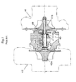
- Fig. 1 is a view showing one example of a conventional exhaust gas turbine supercharger.
- the conventional exhaust gas turbine supercharger is generally constituted by a compressor 41 and a turbine 42 which are arranged so as to provide a bearing unit 40 therebetween, and the compressor 41 and the turbine 42 respectively have a compressor impeller 41a and a turbine impeller 42a built-in.
- the compressor impeller 41a and the turbine impeller 42a are coupled to each other by a connecting shaft (a shaft 43) supported by a bearing unit 40, and are structured such that the turbine impeller 42a is rotationally driven by an exhaust gas of the engine, a rotating force is transmitted to the compressor impeller 41a via the shaft 43, and the air is compressed by the compressor impeller 41a so as to be supercharged to the engine.
- the bearing unit 40 has a radial bearing 44 supporting a radial force of the shaft 43 and a thrust bearing 45 supporting a thrust force.
- the radial bearing 44 is constituted by a full-floating bearing in this example, however, there is a case that it is constituted by a semi-floating bearing.
- the thrust bearing 45 is constituted by a disc-shaped thrust collar 46 rotating together with the shaft 43, and a turbine side thrust bearing 47 and a compressor side thrust bearing 48 which block a movement in an axial direction of the thrust collar 46.
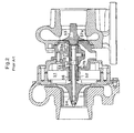
- the turbocharger in the patent document 1 is provided with an electric motor (a stator 51 and a rotor 52) rotationally driving a rotor, as shown in Fig. 2 .
- the rotor is constituted by a turbine impeller 53, a compressor impeller 54, and a spacer collar 56 to which a shaft 55 connecting the impellers and the rotor 52 of the electric motor are attached.
- the shaft 55 is supported by a single semi-floating bearing 57.
- the semi-floating bearing 57 has thrust surfaces 57a and 57b engaging with a hub 53a of the turbine 53 and the spacer collar 56.
- the thrust force applied to the rotor is supported by the thrust surfaces 57a and 57b engaging with the hub 53a of the turbine and the spacer collar 56 in the semi-floating bearing 57.
- Patent Document 1 U.S.P. No. 6,449,950 "ROTOR AND BEARING SYSTEM FOR ELECTRICALLY ASSISTED TURBOCHARGER"
- an object of the present invention is to provide a motor-driven supercharger which can shorten an overhang amount of a shaft, can supply a sufficient amount of lubricating oil to a thrust surface suffered to a great thrust force in a compressor direction, and can smoothly discharge the lubricating oil from the thrust surface, even in the case that a thrust bearing is provided in an outer side of a radial bearing, and an electric motor is provided between the thrust bearing and a compressor impeller.
- a motor-driven supercharger comprising:
- a turbine side coil end of the motor stator is formed as a taper surface in which an inner surface is expanded to the turbine side, and a seal plate comparting between the compressor side thrust bearing and the motor stator is formed in a truncated conical shape positioned in an inner side of the taper surface.
- small-diameter ring portion and the truncated conical portion are formed by an integral structure of separate structures.
- concave grooves facing to each other and extending toward an oil discharge port are provided in an inner surface of the truncated conical portion of the compressor side thrust bearing and an outer surface of the housing facing thereto, and an oil discharge path toward the oil discharge port is formed on the basis of a combination thereof.
- the thrust bearing is constituted by the small-diameter disc-shaped thrust collar rotating together with the turbine shaft, and the turbine side thrust bearing and the compressor side thrust bearing which block the movement in the axial direction of the thrust collar, it is possible to hold the thrust collar by the turbine side thrust bearing and the compressor side thrust bearing so as to rotatably support the thrust forces in both directions applied to the turbine shaft.
- the compressor side thrust bearing is constituted by the small-diameter ring portion and the truncated conical portion, and the turbine side end portion of the truncated conical portion is fixed to the housing in the side closer to the turbine than the thrust collar, it is possible to elongate the radial bearing to the closer side to the compressor than the fixed position of the compressor side thrust bearing, and it is possible to shorten the overhang amount of the shaft at that degree.
- the turbine side coil end of the motor stator is formed as the taper surface in which the inner surface is expanded to the turbine side, and the seal plate comparting between the compressor side thrust bearing and the motor stator is formed in the truncated conical shape positioned in the inner side of the taper surface, it is possible to overlap the compressor side thrust bearing, the seal plate and the turbine side inner surface of the motor state which are respectively formed in the truncated conical shape, in a radial direction at the same position in the axial direction.
- the concave grooves facing to each other and extending toward the oil discharge port are provided in the inner surface of the truncated conical portion of the compressor side thrust bearing and the outer surface of the housing facing thereto, and the oil discharge path toward the oil discharge port is formed on the basis of the combination thereof, it is possible to control the direction of the discharged oil and it is possible to improve an oil discharge property.
- Fig. 3 is a schematic view of a whole of a motor-driven supercharger in accordance with the present invention.
- a motor-driven supercharger 10 in accordance with the present invention is provided with a turbine shaft 12, a compressor impeller 14, and a housing.
- the housing is constituted by a bearing housing 16, a turbine housing 18 and a compressor housing 20, in this embodiment.
- the turbine shaft 12 has a turbine impeller 11 in one end (a left end in the drawing).
- the turbine impeller 11 is integrally formed in the turbine shaft 12, however, the present invention is not limited to this, but may be structured such that the turbine impeller 11 is separately attached.
- the compressor impeller 14 is coupled to the other end (a right end in the drawing) of the turbine shaft 12 in such a manner as to be integrally rotated by a shaft end nut 15.
- the bearing housing 16 rotatably supports the turbine shaft 12 by a radial bearing 17. Further, the turbine shaft 12 is supported by a thrust bearing 30 in such a manner as to be prevented from moving in an axial direction.
- the turbine housing 18 rotatably surrounds the turbine impeller 11, and is coupled to the bearing housing 16.
- the turbine housing 18 has a scroll chamber 18a in which an exhaust gas is introduced to an inner portion from an outer portion, and an annularly formed flow path 18b guiding the exhaust gas from the scroll chamber 18a to the turbine impeller 11.
- a plurality of nozzle vanes 19 are arranged in the flow path 18b at a fixed distance in a peripheral direction.
- the nozzle vane is preferably constituted by a variable nozzle vane, and is structured such that a flow path area formed therebetween can be changed, however, the present invention is not limited to this, but may be constituted by a fixed nozzle vane.
- the compressor housing 20 rotatably surrounds the compressor impeller 14, and is coupled to the bearing housing 16.
- the compressor housing 20 has a scroll chamber 20a in which a compressed air is introduced to an inner portion, and an annularly formed flow path 20b guiding the compressed air from the compressor impeller 14 to the scroll chamber 20a.
- the motor-driven supercharger 10 in accordance with the present invention is further provided with a motor rotor 22 and a motor stator 24.
- the motor rotor 22 corresponds to a rotor of an electric motor
- the motor stator 24 corresponds to a stator of the electric motor.
- a brushless a.c. motor is structured by the motor rotor 22 and the motor stator 24.
- a turbine side coil end 24a of the motor stator 24 is formed in a taper surface in which an inner surface is expanded to the turbine side.
- the taper surface is preferably formed by deforming the coil end 24a, that is, a coil winding by a press molding or the like within a range in which a function is not deteriorated.
- the motor rotor 22 has a shorter shaft length than the motor stator 24, and is preferably fixed so as to close to the compressor impeller 14 of the turbine shaft 12.
- the a.c. motor can correspond to a high-speed rotation (for example, at least 100 to 200 thousands rpm) of the turbine shaft 12, and can execute a rotational drive at a time of accelerating and a regenerating operation at a time of decelerating. Further, it is preferable that a drive voltage of the a.c. motor is equal to or higher (for example, 24 to 36 V) than a d.c. voltage (for example, 12 V) of a battery mounted on a vehicle. It is possible to downsize the a.c. motor by increasing the drive voltage.
- Fig. 4 is a partly enlarged view of Fig. 3 .
- the thrust bearing 30 in accordance with the present invention is constituted by a small-diameter disc-shaped thrust collar 32 rotating together with the turbine shaft 12, and a turbine side thrust bearing 34 and a compressor side thrust bearing 36 which block a movement in an axial direction of the thrust collar 32.
- the compressor side thrust bearing 36 is formed in a truncated conical shape which is constituted by a small-diameter ring portion 37 and a truncated conical portion 38 and is bulged to the compressor side in the center.
- the small-diameter ring portion 37 and the truncated conical portion 38 are formed as an integral structure for reducing a number of the parts.
- the small-diameter ring portion 37 has a thrust surface 37a which is in contact with the thrust collar 32 and has an approximately equal diameter.
- the truncated conical portion 38 has a conical outer surface gradually increasing to the turbine side from an outer peripheral surface of the small-diameter ring portion 37, and a turbine side end portion 38a (that is, a flange portion) thereof is fixed to the housing in a side closer to the turbine than the thrust collar 32.
- the compressor side thrust bearing 36 has the small-diameter ring portion 37 including the thrust surface which is in contact with the thrust collar 32 and has an approximately equal diameter, and a flange portion 38a fixed to the housing in a side closer to the turbine than the thrust collar 32, and the small-diameter ring portion 37 and the flange portion 38a are arranged at different positions in an axial direction.
- the flange portion is positioned in the side closer to the turbine than the small-diameter ring portion 37.
- the compressor side thrust bearing 36 has an oil supply flow path 36a.
- the oil supply flow path 36a has a function of supplying a lubricating oil to a surface (a left surface in the drawing) brought into contact with the thrust collar 32 from an inner side of the bearing housing 16.
- concave grooves 38b and 16b facing to each other and extending toward an oil discharge port are provided below the turbine shaft 12, on an inner surface of the truncated conical portion 38 of the compressor side thrust bearing 36 and an outer surface of the bearing housing 16 facing thereto, and an oil discharge path toward the oil discharge port is formed on the basis of a combination thereof.
- Fig. 5 is a view of the other structure of the compressor side thrust bearing.
- the compressor side thrust bearing 36 is formed in the truncated conical shape which is constituted by the small-diameter ring portion 37 and the truncated conical portion 38 and is bulged to the compressor side in the center.
- the small-diameter ring portion 37 and the truncated conical portion 38 are formed as separate structures integrated in accordance with a fitting or the like for reducing a manufacturing cost.
- the turbine side end portion 38a (that is, the flange portion) is fixed to the housing in the side closer to the turbine than the thrust collar 32, and the flange portion 38a is positioned in a side closer to the turbine side than the small-diameter ring portion 37.
- the thrust bearing is constituted by the small-diameter disc-shaped thrust collar 32 rotating together with the turbine shaft 12, and the turbine side thrust bearing 34 and the compressor side thrust bearing 36 which block the movement in the axial direction of the thrust collar, it is possible to hold the thrust collar 34 by the turbine side thrust bearing 34 and the compressor side thrust bearing 36 so as to rotatably support the thrust forces in both directions applied to the turbine shaft 12.
- the compressor side thrust bearing 36 is constituted by the small-diameter ring portion 37 and the truncated conical portion 38, and the turbine side end portion 38a of the truncated conical portion 38 is fixed to the bearing housing 16 in the side closer to the turbine than the thrust collar 32, it is possible to elongate the radial bearing to the side closer to the compressor than the fixed position of the compressor side thrust bearing 36, and it is possible to shorten the overhang amount of the shaft at that degree.
- the motor rotor 22 is provided between the compressor side thrust bearing 36 and the compressor impeller 14.
- the motor-driven supercharger in accordance with the present invention further has a seal plate 26, an oil thrower member 28 and a seal member 29.
- the seal plate 26 corresponds to a partition wall which is fixed to the bearing housing 16 and comparts between the compressor side thrust bearing 36 and the motor rotor 22, in this embodiment.
- the seal plate 26 is positioned in an inner side of a turbine side taper surface of the motor stator 24 mentioned above, and is formed in a truncated conical shape.
- the oil thrower member 28 is positioned between the seal plate 26 and the compressor side thrust bearing 36, is fixed to the turbine shaft 12 and is rotated together with the turbine shaft 12.
- the oil thrower member 28 has a vertical surface 28a which is larger than a hollow through hole of the compressor side thrust bearing 36, and is approximately orthogonal to the turbine shaft 12.
- the seal member 29 seals in a liquid tight manner between the oil thrower member 28 and the seal plate 26.
Landscapes
- Engineering & Computer Science (AREA)
- Chemical & Material Sciences (AREA)
- Mechanical Engineering (AREA)
- General Engineering & Computer Science (AREA)
- Combustion & Propulsion (AREA)
- Chemical Kinetics & Catalysis (AREA)
- General Chemical & Material Sciences (AREA)
- Supercharger (AREA)
Abstract
Description
- The present invention relates to a motor-driven supercharger having an electric motor built-in.
- To supply an air having a boosted density by a compressor to an engine is called as supercharging, and an apparatus providing for a driving work of the compressor on the basis of an exhaust energy is called as an exhaust gas turbine supercharger (an exhaust-gas turbocharger).
-
Fig. 1 is a view showing one example of a conventional exhaust gas turbine supercharger. As shown in this drawing, the conventional exhaust gas turbine supercharger is generally constituted by acompressor 41 and aturbine 42 which are arranged so as to provide abearing unit 40 therebetween, and thecompressor 41 and theturbine 42 respectively have acompressor impeller 41a and aturbine impeller 42a built-in. Thecompressor impeller 41a and theturbine impeller 42a are coupled to each other by a connecting shaft (a shaft 43) supported by abearing unit 40, and are structured such that theturbine impeller 42a is rotationally driven by an exhaust gas of the engine, a rotating force is transmitted to thecompressor impeller 41a via the shaft 43, and the air is compressed by thecompressor impeller 41a so as to be supercharged to the engine. - Further, in this drawing, the
bearing unit 40 has a radial bearing 44 supporting a radial force of the shaft 43 and a thrust bearing 45 supporting a thrust force. Theradial bearing 44 is constituted by a full-floating bearing in this example, however, there is a case that it is constituted by a semi-floating bearing. - The thrust bearing 45 is constituted by a disc-
shaped thrust collar 46 rotating together with the shaft 43, and a turbine side thrust bearing 47 and a compressor side thrust bearing 48 which block a movement in an axial direction of thethrust collar 46. - On the other hand, in the exhaust gas turbine supercharger mentioned above, there has been already proposed a structure having an electric motor built-in for assisting an acceleration at a time of rotating at a low speed (for example, patent document 1). Hereinafter, the exhaust gas turbine supercharger having the electric motor mentioned above built-in is simply called as "motor-driven supercharger".
- The turbocharger in the patent document 1 is provided with an electric motor (a
stator 51 and a rotor 52) rotationally driving a rotor, as shown inFig. 2 . The rotor is constituted by aturbine impeller 53, acompressor impeller 54, and aspacer collar 56 to which ashaft 55 connecting the impellers and therotor 52 of the electric motor are attached. Theshaft 55 is supported by a single semi-floating bearing 57. The semi-floating bearing 57 hasthrust surfaces hub 53a of theturbine 53 and thespacer collar 56. - In accordance with this structure, the thrust force applied to the rotor is supported by the
thrust surfaces hub 53a of the turbine and thespacer collar 56 in the semi-floating bearing 57. - Patent Document 1:
U.S.P. No. 6,449,950 "ROTOR AND BEARING SYSTEM FOR ELECTRICALLY ASSISTED TURBOCHARGER" - In the exhaust gas turbine supercharger, since a pressure applied to the turbine impeller is generally higher than a pressure applied to the compressor impeller, a great thrust force is generated in a direction toward the compressor impeller.
- Accordingly, it is necessary to supply a sufficient amount of lubricating oil to the thrust bearing supporting a rotating shaft of the exhaust gas turbine supercharger.
- However, in the case that the thrust bearing is provided in an outer side of the radial bearing, and the electric motor is provided between the thrust bearing and the compressor impeller, there is a problem that an overhang amount of the shaft is enlarged at a length of the thrust bearing and the electric motor.
- For example, in the prior art in
Fig. 1 , if the stator and the rotor of the electric motor are provided between thecompressor impeller 41a and theseal plate 49, it is necessary to elongate the overhang amount of the shaft at least at an amount corresponding to the stator of the electric motor, and there is a risk that a rotation stability is lowered at a time of rotating at a high speed. - Further, in the prior art in
Fig. 2 having the stator and the rotor of the electric motor built-in, since a distance between thethrust surfaces thrust surface 57a suffered to the great thrust force in the direction toward the compressor impeller. - The present invention is made for solving the problems mentioned above. In other words, an object of the present invention is to provide a motor-driven supercharger which can shorten an overhang amount of a shaft, can supply a sufficient amount of lubricating oil to a thrust surface suffered to a great thrust force in a compressor direction, and can smoothly discharge the lubricating oil from the thrust surface, even in the case that a thrust bearing is provided in an outer side of a radial bearing, and an electric motor is provided between the thrust bearing and a compressor impeller.
- In accordance with the present invention, there is provided a motor-driven supercharger comprising:
- a compressor impeller;
- a motor stator fixed within a housing; and
- a motor rotor rotationally driven by the motor stator,
- wherein the motor-driven supercharger is provided with a thrust bearing rotatably supporting a thrust force applied to a turbine shaft,
- wherein the thrust bearing is constituted by a small-diameter disc-shaped thrust collar rotating together with a turbine shaft, and a turbine side thrust bearing and a compressor side thrust bearing which block a movement in an axial direction of the thrust collar, and
- wherein the compressor side thrust bearing has a small-diameter ring portion including a thrust surface which is in contact with the thrust collar and has approximately an equal diameter, and a flange portion fixed to the housing in a side closer to the turbine than the thrust collar, and the small-diameter ring portion and the flange portion are arranged at different positions in an axial direction.
- In accordance with a preferable aspect of the present invention, a turbine side coil end of the motor stator is formed as a taper surface in which an inner surface is expanded to the turbine side, and a seal plate comparting between the compressor side thrust bearing and the motor stator is formed in a truncated conical shape positioned in an inner side of the taper surface.
- Further, the small-diameter ring portion and the truncated conical portion are formed by an integral structure of separate structures.
- Further, concave grooves facing to each other and extending toward an oil discharge port are provided in an inner surface of the truncated conical portion of the compressor side thrust bearing and an outer surface of the housing facing thereto, and an oil discharge path toward the oil discharge port is formed on the basis of a combination thereof.
- In accordance with the structure of the present invention mentioned above, since the thrust bearing is constituted by the small-diameter disc-shaped thrust collar rotating together with the turbine shaft, and the turbine side thrust bearing and the compressor side thrust bearing which block the movement in the axial direction of the thrust collar, it is possible to hold the thrust collar by the turbine side thrust bearing and the compressor side thrust bearing so as to rotatably support the thrust forces in both directions applied to the turbine shaft.
- Further, since the compressor side thrust bearing is constituted by the small-diameter ring portion and the truncated conical portion, and the turbine side end portion of the truncated conical portion is fixed to the housing in the side closer to the turbine than the thrust collar, it is possible to elongate the radial bearing to the closer side to the compressor than the fixed position of the compressor side thrust bearing, and it is possible to shorten the overhang amount of the shaft at that degree.
- Further, since the turbine side coil end of the motor stator is formed as the taper surface in which the inner surface is expanded to the turbine side, and the seal plate comparting between the compressor side thrust bearing and the motor stator is formed in the truncated conical shape positioned in the inner side of the taper surface, it is possible to overlap the compressor side thrust bearing, the seal plate and the turbine side inner surface of the motor state which are respectively formed in the truncated conical shape, in a radial direction at the same position in the axial direction.
- Therefore, in accordance with this structure, even in the case that the electric motor is provided between the thrust bearing and the compressor impeller, it is possible to shorten the overhang amount of the shaft.
- Further, it is possible to reduce a number of the parts by integrally structuring the small-diameter ring portion and the truncated conical portion. Further, it is possible to reduce a manufacturing cost by inversely integrating in accordance with a fitting or the like on the basis of the separate structure.
- Further, in the case that the concave grooves facing to each other and extending toward the oil discharge port are provided in the inner surface of the truncated conical portion of the compressor side thrust bearing and the outer surface of the housing facing thereto, and the oil discharge path toward the oil discharge port is formed on the basis of the combination thereof, it is possible to control the direction of the discharged oil and it is possible to improve an oil discharge property.
-
-
Fig. 1 is a view showing an example of a conventional exhaust gas turbine supercharger; -
Fig. 2 is a schematic view of a turbo charger of patent document 1; -
Fig. 3 is a schematic view of a whole of a motor-driven supercharger in accordance with the present invention; -
Fig. 4 is a partly enlarged view ofFig. 3 ; and -
Fig. 5 is a view of the other structure of a compressor side thrust bearing. - A description will be given below of preferable embodiments in accordance with the present invention with reference to the accompanying drawings. In this case, in each of the drawings, the same reference numerals are attached to the common portions in each of the drawings, and an overlapping description will be omitted.
-
Fig. 3 is a schematic view of a whole of a motor-driven supercharger in accordance with the present invention. In this drawing, a motor-drivensupercharger 10 in accordance with the present invention is provided with aturbine shaft 12, acompressor impeller 14, and a housing. The housing is constituted by a bearinghousing 16, a turbine housing 18 and acompressor housing 20, in this embodiment. - The
turbine shaft 12 has aturbine impeller 11 in one end (a left end in the drawing). In this embodiment, theturbine impeller 11 is integrally formed in theturbine shaft 12, however, the present invention is not limited to this, but may be structured such that theturbine impeller 11 is separately attached. - The
compressor impeller 14 is coupled to the other end (a right end in the drawing) of theturbine shaft 12 in such a manner as to be integrally rotated by ashaft end nut 15. - The bearing
housing 16 rotatably supports theturbine shaft 12 by a radial bearing 17. Further, theturbine shaft 12 is supported by a thrust bearing 30 in such a manner as to be prevented from moving in an axial direction. - The
turbine housing 18 rotatably surrounds theturbine impeller 11, and is coupled to the bearinghousing 16. Theturbine housing 18 has ascroll chamber 18a in which an exhaust gas is introduced to an inner portion from an outer portion, and an annularly formedflow path 18b guiding the exhaust gas from thescroll chamber 18a to theturbine impeller 11. - Further, a plurality of
nozzle vanes 19 are arranged in theflow path 18b at a fixed distance in a peripheral direction. The nozzle vane is preferably constituted by a variable nozzle vane, and is structured such that a flow path area formed therebetween can be changed, however, the present invention is not limited to this, but may be constituted by a fixed nozzle vane. - The
compressor housing 20 rotatably surrounds thecompressor impeller 14, and is coupled to the bearinghousing 16. Thecompressor housing 20 has ascroll chamber 20a in which a compressed air is introduced to an inner portion, and an annularly formedflow path 20b guiding the compressed air from thecompressor impeller 14 to thescroll chamber 20a. - In accordance with the structure mentioned above, it is possible to rotationally drive the
turbine impeller 11 by the exhaust gas of the engine, transmit the rotating force to thecompressor impeller 14 via theturbine shaft 12 and compress the air by thecompressor impeller 14 so as to supercharge to the engine. - Further, in
Fig. 3 , the motor-drivensupercharger 10 in accordance with the present invention is further provided with amotor rotor 22 and amotor stator 24. - The
motor rotor 22 corresponds to a rotor of an electric motor, and themotor stator 24 corresponds to a stator of the electric motor. A brushless a.c. motor is structured by themotor rotor 22 and themotor stator 24. - In the present invention, a turbine
side coil end 24a of themotor stator 24 is formed in a taper surface in which an inner surface is expanded to the turbine side. The taper surface is preferably formed by deforming thecoil end 24a, that is, a coil winding by a press molding or the like within a range in which a function is not deteriorated. - Further, the
motor rotor 22 has a shorter shaft length than themotor stator 24, and is preferably fixed so as to close to thecompressor impeller 14 of theturbine shaft 12. - It is preferable that the a.c. motor can correspond to a high-speed rotation (for example, at least 100 to 200 thousands rpm) of the
turbine shaft 12, and can execute a rotational drive at a time of accelerating and a regenerating operation at a time of decelerating. Further, it is preferable that a drive voltage of the a.c. motor is equal to or higher (for example, 24 to 36 V) than a d.c. voltage (for example, 12 V) of a battery mounted on a vehicle. It is possible to downsize the a.c. motor by increasing the drive voltage. -
Fig. 4 is a partly enlarged view ofFig. 3 . As shown in this drawing, the thrust bearing 30 in accordance with the present invention is constituted by a small-diameter disc-shapedthrust collar 32 rotating together with theturbine shaft 12, and a turbine side thrust bearing 34 and a compressor side thrust bearing 36 which block a movement in an axial direction of thethrust collar 32. - The compressor side thrust bearing 36 is formed in a truncated conical shape which is constituted by a small-
diameter ring portion 37 and a truncatedconical portion 38 and is bulged to the compressor side in the center. In this example, the small-diameter ring portion 37 and the truncatedconical portion 38 are formed as an integral structure for reducing a number of the parts. - The small-
diameter ring portion 37 has athrust surface 37a which is in contact with thethrust collar 32 and has an approximately equal diameter. The truncatedconical portion 38 has a conical outer surface gradually increasing to the turbine side from an outer peripheral surface of the small-diameter ring portion 37, and a turbineside end portion 38a (that is, a flange portion) thereof is fixed to the housing in a side closer to the turbine than thethrust collar 32. - In other words, the compressor side thrust bearing 36 has the small-
diameter ring portion 37 including the thrust surface which is in contact with thethrust collar 32 and has an approximately equal diameter, and aflange portion 38a fixed to the housing in a side closer to the turbine than thethrust collar 32, and the small-diameter ring portion 37 and theflange portion 38a are arranged at different positions in an axial direction. - Accordingly, the flange portion is positioned in the side closer to the turbine than the small-
diameter ring portion 37. - The compressor side thrust bearing 36 has an oil
supply flow path 36a. - The oil
supply flow path 36a has a function of supplying a lubricating oil to a surface (a left surface in the drawing) brought into contact with thethrust collar 32 from an inner side of the bearinghousing 16. - Further,
concave grooves turbine shaft 12, on an inner surface of the truncatedconical portion 38 of the compressorside thrust bearing 36 and an outer surface of the bearinghousing 16 facing thereto, and an oil discharge path toward the oil discharge port is formed on the basis of a combination thereof. -
Fig. 5 is a view of the other structure of the compressor side thrust bearing. - In this drawing, the compressor side thrust bearing 36 is formed in the truncated conical shape which is constituted by the small-
diameter ring portion 37 and the truncatedconical portion 38 and is bulged to the compressor side in the center. Further, in this example, the small-diameter ring portion 37 and the truncatedconical portion 38 are formed as separate structures integrated in accordance with a fitting or the like for reducing a manufacturing cost. In this example, the turbineside end portion 38a (that is, the flange portion) is fixed to the housing in the side closer to the turbine than thethrust collar 32, and theflange portion 38a is positioned in a side closer to the turbine side than the small-diameter ring portion 37. - The other structures are the same as
Fig. 4 . - In accordance with the structure of the present invention mentioned above, since the thrust bearing is constituted by the small-diameter disc-shaped
thrust collar 32 rotating together with theturbine shaft 12, and the turbine side thrust bearing 34 and the compressor side thrust bearing 36 which block the movement in the axial direction of the thrust collar, it is possible to hold the thrust collar 34 by the turbine side thrust bearing 34 and the compressor side thrust bearing 36 so as to rotatably support the thrust forces in both directions applied to theturbine shaft 12. - Further, since the compressor side thrust bearing 36 is constituted by the small-
diameter ring portion 37 and the truncatedconical portion 38, and the turbineside end portion 38a of the truncatedconical portion 38 is fixed to the bearinghousing 16 in the side closer to the turbine than thethrust collar 32, it is possible to elongate the radial bearing to the side closer to the compressor than the fixed position of the compressorside thrust bearing 36, and it is possible to shorten the overhang amount of the shaft at that degree. - Further, it is possible to control the direction of the discharged oil and it is possible to improve an oil discharge property, by setting the
concave grooves conical portion 38 of the compressorside thrust bearing 36 and the outer surface of the bearinghousing 16 facing thereto, and forming the oil discharge path toward the oil discharge port on the basis of the combination thereof. - In
Figs. 3 and4 , themotor rotor 22 is provided between the compressorside thrust bearing 36 and thecompressor impeller 14. - Further, the motor-driven supercharger in accordance with the present invention further has a
seal plate 26, anoil thrower member 28 and aseal member 29. - The
seal plate 26 corresponds to a partition wall which is fixed to the bearinghousing 16 and comparts between the compressorside thrust bearing 36 and themotor rotor 22, in this embodiment. In the present invention, theseal plate 26 is positioned in an inner side of a turbine side taper surface of themotor stator 24 mentioned above, and is formed in a truncated conical shape. - In accordance with this structure, it is possible to overlap the compressor
side thrust bearing 36, theseal plate 26 and the turbine side inner surface of themotor stator 24 which are respectively formed in the truncated conical shape, in a radial direction at an equal position in the axial direction. - Therefore, in accordance with this structure, even in the case that the electric motor is provided between the thrust bearing and the compressor impeller, it is possible to shorten the overhang amount of the shaft.
- Further, the
oil thrower member 28 is positioned between theseal plate 26 and the compressorside thrust bearing 36, is fixed to theturbine shaft 12 and is rotated together with theturbine shaft 12. Theoil thrower member 28 has avertical surface 28a which is larger than a hollow through hole of the compressorside thrust bearing 36, and is approximately orthogonal to theturbine shaft 12. - The
seal member 29 seals in a liquid tight manner between theoil thrower member 28 and theseal plate 26. - In this case, it goes without saying that the present invention is not limited to the embodiments mentioned above, but can be variously modified within the scope of the present invention.
Claims (3)
- A motor-driven supercharger comprising:a turbine shaft having a turbine impeller in one end;a compressor impeller rotationally driven by the turbine shaft;a motor stator fixed within a housing; anda motor rotor rotationally driven by the motor stator,wherein the motor-driven supercharger is provided with a thrust bearing rotatably supporting a thrust force applied to a turbine shaft,wherein the thrust bearing is constituted by a small-diameter disc-shaped thrust collar rotating together with a turbine shaft, and a turbine side thrust bearing and a compressor side thrust bearing which block a movement in an axial direction of the thrust collar, andwherein the compressor side thrust bearing has a small-diameter ring portion including a thrust surface which is in contact with the thrust collar and has approximately an equal diameter, and a flange portion fixed to the housing in the turbine side, and the small-diameter ring portion and the flange portion are different at positions in an axial direction.
- A motor-driven supercharger as claimed in claim 1, wherein a turbine side coil end of the motor stator is formed as a taper surface in which an inner surface is expanded to the turbine side, and a seal plate comparting between the compressor side thrust bearing and the motor stator is formed in a truncated conical shape positioned in an inner side of the taper surface.
- A motor-driven supercharger as claimed in claim 2, wherein concave grooves facing to each other and extending toward an oil discharge port are provided in an inner surface of the truncated conical portion of the compressor side thrust bearing and an outer surface of the housing facing thereto, and an oil discharge path toward the oil discharge port is formed on the basis of a combination thereof.
Applications Claiming Priority (2)
| Application Number | Priority Date | Filing Date | Title |
|---|---|---|---|
| JP2006154517A JP4753033B2 (en) | 2006-06-02 | 2006-06-02 | Electric turbocharger |
| PCT/JP2007/058947 WO2007141969A1 (en) | 2006-06-02 | 2007-04-25 | Electric supercharger |
Publications (3)
| Publication Number | Publication Date |
|---|---|
| EP2025892A1 true EP2025892A1 (en) | 2009-02-18 |
| EP2025892A4 EP2025892A4 (en) | 2013-06-19 |
| EP2025892B1 EP2025892B1 (en) | 2014-07-02 |
Family
ID=38801234
Family Applications (1)
| Application Number | Title | Priority Date | Filing Date |
|---|---|---|---|
| EP07742382.0A Active EP2025892B1 (en) | 2006-06-02 | 2007-04-25 | Electric supercharger |
Country Status (6)
| Country | Link |
|---|---|
| US (1) | US8001781B2 (en) |
| EP (1) | EP2025892B1 (en) |
| JP (1) | JP4753033B2 (en) |
| KR (1) | KR101117943B1 (en) |
| CN (1) | CN101460724B (en) |
| WO (1) | WO2007141969A1 (en) |
Cited By (1)
| Publication number | Priority date | Publication date | Assignee | Title |
|---|---|---|---|---|
| WO2016153963A1 (en) * | 2015-03-26 | 2016-09-29 | Borgwarner Inc. | Oil deflector with oil guide |
Families Citing this family (29)
| Publication number | Priority date | Publication date | Assignee | Title |
|---|---|---|---|---|
| US8157543B2 (en) | 2006-03-23 | 2012-04-17 | Ihi Corporation | High-speed rotating shaft of supercharger |
| JP4671177B2 (en) | 2006-06-02 | 2011-04-13 | 株式会社Ihi | Electric turbocharger |
| JP4753033B2 (en) * | 2006-06-02 | 2011-08-17 | 株式会社Ihi | Electric turbocharger |
| WO2008020512A1 (en) | 2006-08-18 | 2008-02-21 | Ihi Corporation | Electric supercharger |
| US8157544B2 (en) | 2006-08-18 | 2012-04-17 | Ihi Corporation | Motor driven supercharger with motor/generator cooling efficacy |
| EP2241735A4 (en) * | 2008-01-28 | 2017-08-02 | IHI Corporation | Supercharger |
| JP5464470B2 (en) * | 2009-06-09 | 2014-04-09 | 株式会社Ihi | Turbocharger oil seal structure |
| KR101779897B1 (en) * | 2010-08-24 | 2017-09-19 | 보르그워너 인코퍼레이티드 | Bearing housing of an exhaust-gas turbocharger |
| DE102010043198B4 (en) * | 2010-11-01 | 2022-06-02 | Abb Schweiz Ag | Burst protection for an exhaust gas turbocharger |
| JP5978947B2 (en) | 2012-11-21 | 2016-08-24 | 株式会社Ihi | Turbocharger |
| US9670935B2 (en) * | 2013-05-30 | 2017-06-06 | Ingersoll-Rand Company | Centrifugal compressor having seal system |
| JP6217391B2 (en) | 2013-12-27 | 2017-10-25 | 株式会社Ihi | Bearing structure and turbocharger |
| DE102015204563A1 (en) * | 2015-03-13 | 2016-09-15 | Bayerische Motoren Werke Aktiengesellschaft | turbocharger |
| JP6550947B2 (en) | 2015-06-11 | 2019-07-31 | 株式会社Ihi | Rotating machine |
| JP6439873B2 (en) | 2015-07-22 | 2018-12-19 | 株式会社Ihi | Oil seal structure and turbocharger |
| JP6418331B2 (en) * | 2015-08-11 | 2018-11-07 | 株式会社Ihi | Bearing structure and turbocharger |
| CN107850125B (en) * | 2015-08-11 | 2019-08-16 | 株式会社Ihi | Bearing structure and supercharger |
| US9638203B2 (en) * | 2015-09-15 | 2017-05-02 | Borgwarner Inc. | Bearing housing |
| JP6705146B2 (en) | 2015-10-07 | 2020-06-03 | 株式会社Ihi | Variable flow valve mechanism and supercharger |
| WO2017170753A1 (en) | 2016-03-31 | 2017-10-05 | 株式会社Ihi | Supercharger |
| US10927759B2 (en) | 2016-05-20 | 2021-02-23 | Ihi Corporation | Bearing structure for turbocharger and turbocharger |
| CN109790854B (en) | 2016-11-21 | 2021-02-23 | 株式会社Ihi | Electric compressor |
| JP6794922B2 (en) * | 2017-05-12 | 2020-12-02 | 株式会社豊田自動織機 | Electric supercharger |
| DE102017120338A1 (en) * | 2017-09-05 | 2019-03-07 | Man Diesel & Turbo Se | turbocharger |
| JP2020041470A (en) * | 2018-09-10 | 2020-03-19 | トヨタ自動車株式会社 | compressor |
| JP7119829B2 (en) * | 2018-09-25 | 2022-08-17 | トヨタ自動車株式会社 | turbocharger |
| US11125109B2 (en) * | 2020-01-31 | 2021-09-21 | Unison Industries, Llc | Foil-air bearing assembly for engine starter |
| CN114746638B (en) * | 2020-03-24 | 2024-08-27 | 株式会社Ihi | Supercharger |
| CN113814684B (en) * | 2020-06-18 | 2022-10-28 | 中国航发商用航空发动机有限责任公司 | Decomposition process method of low-pressure turbine shaft |
Family Cites Families (109)
| Publication number | Priority date | Publication date | Assignee | Title |
|---|---|---|---|---|
| CH266731A (en) | 1948-08-11 | 1950-02-15 | Siegfried Keller & Co | Device to avoid loss of lubricant in high-speed turbo machines with a flying rotor arrangement. |
| US3096126A (en) * | 1960-09-26 | 1963-07-02 | Schwitzer Corp | Anti-whirl bearing |
| US3742123A (en) | 1970-11-25 | 1973-06-26 | L Haub | Insulator for electric wires |
| US3675056A (en) | 1971-01-04 | 1972-07-04 | Gen Electric | Hermetically sealed dynamoelectric machine |
| US3778194A (en) | 1972-08-28 | 1973-12-11 | Carrier Corp | Turbocharger structure |
| GB1430308A (en) * | 1973-04-06 | 1976-03-31 | Woollenweber W E | Rotatable assembly |
| US3927530A (en) | 1974-05-28 | 1975-12-23 | Anton Braun | Supercharged internal combustion engine |
| JPS5460109U (en) | 1977-10-06 | 1979-04-25 | ||
| DE2823261C2 (en) | 1978-05-27 | 1985-05-23 | Robert Bosch Gmbh, 7000 Stuttgart | Electric machine |
| US4301375A (en) | 1980-01-02 | 1981-11-17 | Sea Solar Power, Inc. | Turbo-generator unit and system |
| FR2516168B1 (en) | 1981-11-10 | 1986-10-31 | Microturbo Sa | TURBO COMPRESSOR OF AN EXPLOSION ENGINE |
| JPS58124024A (en) * | 1982-01-18 | 1983-07-23 | Nissan Motor Co Ltd | Bearing device for turbosupercharger |
| JPS59134167U (en) | 1983-02-25 | 1984-09-07 | 松下電器産業株式会社 | Holding device for display bodies in electronic equipment, etc. |
| US4641977A (en) | 1983-04-11 | 1987-02-10 | Woollenweber William E | Bearing system |
| JPS60153826A (en) | 1984-01-24 | 1985-08-13 | 松下電器産業株式会社 | Hand mixer |
| HU203622B (en) | 1984-06-04 | 1991-08-28 | Ganz Villamossagi Muevek | Method for regulating loadibility of the air-cooled high-speed turbo generators and arrangement for implementing said method |
| JPH071007B2 (en) * | 1984-08-16 | 1995-01-11 | ヤマハ発動機株式会社 | Intake device for 4-stroke internal combustion engine |
| JPS6149126U (en) * | 1984-09-04 | 1986-04-02 | ||
| JPS61237830A (en) | 1985-04-11 | 1986-10-23 | Isuzu Motors Ltd | Turbo-charger for internal-combustion engine |
| EP0210833B1 (en) | 1985-07-26 | 1991-06-26 | Isuzu Motors Limited | Control system for a supercharged internal combustion engine |
| KR900001291B1 (en) | 1985-08-28 | 1990-03-05 | 이스즈지도샤 가부시끼가이샤 | Auxiliary apparatus for internal combustion engine |
| JPS6251729A (en) | 1985-08-30 | 1987-03-06 | Isuzu Motors Ltd | Turbocharger control device for internal combustion engine |
| US4704075A (en) | 1986-01-24 | 1987-11-03 | Johnston Andrew E | Turbocharger water-cooled bearing housing |
| JPS6419122A (en) | 1987-07-13 | 1989-01-23 | Isuzu Motors Ltd | Turbocharger with revolving armature |
| JPS6445922A (en) | 1987-08-17 | 1989-02-20 | Isuzu Motors Ltd | Turbocharger |
| JPH01171006A (en) | 1987-12-26 | 1989-07-06 | Okuma Mach Works Ltd | Main shaft built-in type motor cooling system |
| JPH0299722A (en) | 1988-10-07 | 1990-04-11 | Isuzu Ceramics Kenkyusho:Kk | Turbo charger |
| JPH02241339A (en) | 1989-03-14 | 1990-09-26 | Hitachi Ltd | Permanent magnet rotor for turbo-charger directly-connecting rotary machine |
| JPH03138430A (en) | 1989-10-23 | 1991-06-12 | Isuzu Ceramics Kenkyusho:Kk | Transfer vehicle for office work |
| JP3047024B2 (en) | 1990-09-10 | 2000-05-29 | ルビコン株式会社 | Solid electrolytic capacitors |
| DE4115273C1 (en) | 1991-05-10 | 1992-06-04 | J.M. Voith Gmbh, 7920 Heidenheim, De | |
| JPH05280362A (en) | 1992-03-31 | 1993-10-26 | Isuzu Motors Ltd | Voltage control device for rotary electric machine for turbocharger |
| JP2924481B2 (en) * | 1992-07-20 | 1999-07-26 | 石川島播磨重工業株式会社 | Turbocharger thrust bearing device |
| US5587332A (en) | 1992-09-01 | 1996-12-24 | Vlsi Technology, Inc. | Method of making flash memory cell |
| JP3239525B2 (en) * | 1993-03-31 | 2001-12-17 | いすゞ自動車株式会社 | Turbocharger with energy recovery device |
| JPH06346748A (en) | 1993-06-03 | 1994-12-20 | Isuzu Motors Ltd | Power unit control device for rotary electric machine for turbo |
| JP3166450B2 (en) | 1993-10-04 | 2001-05-14 | いすゞ自動車株式会社 | Exhaust energy recovery device |
| US5605045A (en) | 1995-09-18 | 1997-02-25 | Turbodyne Systems, Inc. | Turbocharging system with integral assisting electric motor and cooling system therefor |
| JP3289581B2 (en) | 1995-11-13 | 2002-06-10 | 住友電装株式会社 | Heat-resistant electric wire and method of manufacturing heat-resistant electric wire |
| US5906098A (en) | 1996-07-16 | 1999-05-25 | Turbodyne Systems, Inc. | Motor-generator assisted turbocharging systems for use with internal combustion engines and control method therefor |
| US6032466A (en) * | 1996-07-16 | 2000-03-07 | Turbodyne Systems, Inc. | Motor-assisted turbochargers for internal combustion engines |
| US5870894A (en) | 1996-07-16 | 1999-02-16 | Turbodyne Systems, Inc. | Motor-assisted supercharging devices for internal combustion engines |
| US5904471A (en) | 1996-12-20 | 1999-05-18 | Turbodyne Systems, Inc. | Cooling means for a motor-driven centrifugal air compressor |
| US5857332A (en) * | 1996-12-20 | 1999-01-12 | Turbodyne Systems, Inc. | Bearing systems for motor-assisted turbochargers for internal combustion engines |
| US5798587A (en) | 1997-01-22 | 1998-08-25 | Industrial Technology Research Institute | Cooling loop structure of high speed spindle |
| WO1998041029A1 (en) | 1997-03-12 | 1998-09-17 | Matsushita Electric Industrial Co., Ltd. | Upsampling filter and half-pixel generator for an hdtv downconversion system |
| JPH10299500A (en) | 1997-04-22 | 1998-11-10 | Hitachi Ltd | Supercharger |
| US6102672A (en) | 1997-09-10 | 2000-08-15 | Turbodyne Systems, Inc. | Motor-driven centrifugal air compressor with internal cooling airflow |
| JPH11182259A (en) | 1997-12-24 | 1999-07-06 | Aisin Seiki Co Ltd | Turbocharger with rotating electric machine |
| DE19845375A1 (en) | 1998-10-02 | 2000-04-06 | Asea Brown Boveri | Indirect cooling process for flow in gap between turbine rotor and stator, involving use of water to cool stator part adjacent to gap |
| US6145314A (en) | 1998-09-14 | 2000-11-14 | Turbodyne Systems, Inc. | Compressor wheels and magnet assemblies for internal combustion engine supercharging devices |
| JP2000110577A (en) | 1998-10-01 | 2000-04-18 | Nissan Diesel Motor Co Ltd | Bearing device for turbocharger |
| JP2000130176A (en) | 1998-10-30 | 2000-05-09 | Isuzu Motors Ltd | Turbocharger with generator / motor |
| JP3587350B2 (en) | 1998-11-09 | 2004-11-10 | いすゞ自動車株式会社 | Turbocharger with generator / motor |
| US6129524A (en) | 1998-12-07 | 2000-10-10 | Turbodyne Systems, Inc. | Motor-driven centrifugal air compressor with axial airflow |
| JP3877894B2 (en) | 1999-01-13 | 2007-02-07 | 三菱電機株式会社 | Brushless AC generator for vehicles |
| DE19904148C1 (en) | 1999-02-03 | 2000-10-12 | Pierburg Ag | Electric feed pump |
| US6278199B1 (en) | 1999-02-25 | 2001-08-21 | International Rectifier Corp. | Electronic single switch module |
| JP3877899B2 (en) | 1999-03-09 | 2007-02-07 | 三菱電機株式会社 | AC generator for vehicles |
| US6739288B1 (en) * | 2000-01-14 | 2004-05-25 | Tvl Co., Ltd. | Steam heating device |
| DE10003153A1 (en) | 2000-01-26 | 2001-08-02 | Leybold Vakuum Gmbh | Turbo radial fan |
| JP4407780B2 (en) | 2000-04-11 | 2010-02-03 | 株式会社Ihi | Turbocharger bearing structure |
| DE10022113A1 (en) | 2000-05-06 | 2001-11-15 | Daimler Chrysler Ag | Motor vehicle hybrid drive has controller that regulates charging pressure depending on operating conditions, limits charging pressure by regulating electrical power of electrical machine |
| US6449950B1 (en) * | 2000-09-12 | 2002-09-17 | Honeywell International Inc. | Rotor and bearing system for electrically assisted turbocharger |
| CA2399534C (en) * | 2001-08-31 | 2007-01-02 | Mitsubishi Heavy Industries, Ltd. | Gasturbine and the combustor thereof |
| US6609375B2 (en) | 2001-09-14 | 2003-08-26 | Honeywell International Inc. | Air cooling system for electric assisted turbocharger |
| DE10156704A1 (en) | 2001-11-13 | 2003-05-22 | Iav Gmbh | Method and appliance for operating exhaust gas turbocharger for IC engines with electrically assisted drive based on comparison of actual operating conditions and family of operating characteristics |
| JP2003232340A (en) * | 2002-02-08 | 2003-08-22 | Mitsubishi Heavy Ind Ltd | Thrust bearing |
| JP3843932B2 (en) | 2002-03-26 | 2006-11-08 | トヨタ自動車株式会社 | Turbocharger |
| JP2003293785A (en) | 2002-04-03 | 2003-10-15 | Toyota Motor Corp | Turbocharger |
| GB2388404B (en) | 2002-05-09 | 2005-06-01 | Dana Automotive Ltd | Electric pump |
| JP4061994B2 (en) | 2002-07-10 | 2008-03-19 | 株式会社Ihi | Turbocharger |
| JP2004044452A (en) | 2002-07-10 | 2004-02-12 | Ishikawajima Harima Heavy Ind Co Ltd | Supercharger |
| US6647724B1 (en) | 2002-07-30 | 2003-11-18 | Honeywell International Inc. | Electric boost and/or generator |
| TW591237B (en) | 2002-07-31 | 2004-06-11 | Advanced Semiconductor Eng | Semiconductor wafer and testing method for the same |
| DE50208549D1 (en) | 2002-09-02 | 2006-12-07 | Borgwarner Inc | Shaft seal for turbocharger |
| US6668553B1 (en) | 2002-09-13 | 2003-12-30 | Honeywell International Inc. | Ejector-based cooling system for turbochargers |
| DE10245798B4 (en) | 2002-10-01 | 2004-08-19 | Robert Bosch Gmbh | Electrically operated charge air compressor with integrated air cooling |
| GB0224723D0 (en) | 2002-10-24 | 2002-12-04 | Holset Engineering Co | Compressor wheel assembly |
| CN2605696Y (en) | 2003-03-19 | 2004-03-03 | 哈尔滨工业大学新型热能有限责任公司 | Liquid-flow thermal energy generator for enclosed water-cooled motor |
| JP2006514526A (en) * | 2003-04-15 | 2006-04-27 | ハネウェル・インターナショナル・インコーポレーテッド | Electric motor cartridge for electric assist turbocharger |
| DE10325980A1 (en) | 2003-06-07 | 2004-12-23 | Daimlerchrysler Ag | Exhaust gas turbocharger for internal combustion engine has at least one nozzle for subjecting wheel back to cooling fluid arranged close to rotation axis of compressor wheel |
| JP2005023920A (en) | 2003-06-10 | 2005-01-27 | Ishikawajima Harima Heavy Ind Co Ltd | Turbocharger bearing structure |
| JP2005069178A (en) | 2003-08-27 | 2005-03-17 | Toyota Motor Corp | Supercharger with electric motor |
| EP1664503B1 (en) | 2003-09-05 | 2006-06-14 | Honeywell International, Inc. | Electronic power connection for electrically assisted turbocharger |
| JP4182846B2 (en) | 2003-09-05 | 2008-11-19 | トヨタ自動車株式会社 | Control device for internal combustion engine |
| WO2005028876A1 (en) | 2003-09-25 | 2005-03-31 | Abb Research Ltd. | Compressor cleaning system |
| JP4372511B2 (en) | 2003-10-17 | 2009-11-25 | トヨタ自動車株式会社 | Supercharger with rotating electric machine having a cylindrical member extending between bearings |
| US6845617B1 (en) * | 2003-12-20 | 2005-01-25 | Honeywell International Inc | Center housing design for electric assisted turbocharger |
| US6871499B1 (en) | 2003-12-20 | 2005-03-29 | Honeywell Interntional, Inc. | Oil pressure detector for electric assisted turbocharger |
| JP2005207337A (en) * | 2004-01-23 | 2005-08-04 | Toyota Central Res & Dev Lab Inc | Turbocharger and its thrust gas bearing |
| JP4367628B2 (en) * | 2004-03-03 | 2009-11-18 | 株式会社ジェイテクト | Electric motor integrated turbocharger |
| US7056103B2 (en) | 2004-03-05 | 2006-06-06 | Honeywell International, Inc. | Method and apparatus for cooling turbomachinery components |
| JP4151610B2 (en) | 2004-05-19 | 2008-09-17 | トヨタ自動車株式会社 | Motor-assisted turbocharger with cooling device |
| EP1799982A1 (en) * | 2004-10-12 | 2007-06-27 | Honeywell International, Inc. | Electrically assisted turbocharger |
| US7360361B2 (en) | 2005-04-09 | 2008-04-22 | Advanced Propulsion Technologies, Inc. | Turbocharger |
| JP4605380B2 (en) * | 2005-08-08 | 2011-01-05 | 株式会社Ihi | Electric turbocharger |
| JP4692820B2 (en) | 2005-08-11 | 2011-06-01 | 株式会社Ihi | Supercharger with electric motor |
| DE102005052363A1 (en) | 2005-11-02 | 2007-05-03 | Siemens Ag | Electric motor for actuation of camshaft in motor vehicle, has cup-shaped outer cover arranged around sleeve that is washed with cooling medium, where cover has cooling medium inlet and cooling medium outlet |
| JP2007297973A (en) * | 2006-04-28 | 2007-11-15 | Ihi Corp | Supercharger |
| JP4671177B2 (en) * | 2006-06-02 | 2011-04-13 | 株式会社Ihi | Electric turbocharger |
| JP4753033B2 (en) * | 2006-06-02 | 2011-08-17 | 株式会社Ihi | Electric turbocharger |
| JP2008031949A (en) * | 2006-07-31 | 2008-02-14 | Ihi Corp | Supercharger |
| US7677041B2 (en) * | 2006-10-11 | 2010-03-16 | Woollenweber William E | Bearing systems for high-speed rotating machinery |
| JP2009013966A (en) * | 2007-07-09 | 2009-01-22 | Ihi Corp | Supercharger with electric motor |
| JP2009143365A (en) * | 2007-12-13 | 2009-07-02 | Nsk Ltd | Electric power steering device |
| JP5105304B2 (en) * | 2008-03-31 | 2012-12-26 | 株式会社Ihi | Turbocharger system |
| JP5277901B2 (en) * | 2008-11-21 | 2013-08-28 | 株式会社Ihi | Lubricating oil seal structure for vehicle turbocharger |
| US20100175377A1 (en) * | 2009-01-12 | 2010-07-15 | Will Hippen | Cooling an electrically controlled turbocharger |
-
2006
- 2006-06-02 JP JP2006154517A patent/JP4753033B2/en not_active Expired - Lifetime
-
2007
- 2007-04-25 WO PCT/JP2007/058947 patent/WO2007141969A1/en not_active Ceased
- 2007-04-25 US US12/300,746 patent/US8001781B2/en active Active
- 2007-04-25 KR KR1020087028778A patent/KR101117943B1/en not_active Expired - Fee Related
- 2007-04-25 EP EP07742382.0A patent/EP2025892B1/en active Active
- 2007-04-25 CN CN2007800204562A patent/CN101460724B/en active Active
Cited By (3)
| Publication number | Priority date | Publication date | Assignee | Title |
|---|---|---|---|---|
| WO2016153963A1 (en) * | 2015-03-26 | 2016-09-29 | Borgwarner Inc. | Oil deflector with oil guide |
| CN107407161A (en) * | 2015-03-26 | 2017-11-28 | 博格华纳公司 | Oil deflector with oily guider |
| US10539145B2 (en) | 2015-03-26 | 2020-01-21 | Borgwarner Inc. | Oil deflector with oil guide |
Also Published As
| Publication number | Publication date |
|---|---|
| JP2007321698A (en) | 2007-12-13 |
| KR101117943B1 (en) | 2012-02-29 |
| CN101460724A (en) | 2009-06-17 |
| JP4753033B2 (en) | 2011-08-17 |
| US20100218499A1 (en) | 2010-09-02 |
| KR20090009256A (en) | 2009-01-22 |
| US8001781B2 (en) | 2011-08-23 |
| CN101460724B (en) | 2011-07-06 |
| WO2007141969A1 (en) | 2007-12-13 |
| EP2025892B1 (en) | 2014-07-02 |
| EP2025892A4 (en) | 2013-06-19 |
Similar Documents
| Publication | Publication Date | Title |
|---|---|---|
| EP2025892B1 (en) | Electric supercharger | |
| EP2031742B1 (en) | Motor rotor and method of correcting rotational balance of the same | |
| EP2025891B1 (en) | Electric supercharger | |
| US8622691B2 (en) | Supercharger | |
| EP2031732A1 (en) | Motor rotor | |
| EP1752635B1 (en) | Motor-driven supercharger | |
| US20070204615A1 (en) | Two-shaft turbocharger | |
| EP2053213A1 (en) | Electric supercharger | |
| CN105782073B (en) | Multistage Radial Compressor Baffle | |
| JP6128129B2 (en) | Method for manufacturing variable capacity supercharger and housing for variable capacity supercharger | |
| KR20020075239A (en) | Electrically operated charging air compressor | |
| EP1762713A2 (en) | Bearing structure of motor-driven supercharger | |
| CN101663472B (en) | Variable turbine geometry turbocharger | |
| CN104508277B (en) | Variable nozzle unit and variable capacity booster | |
| EP3379034B1 (en) | Turbine de-swirl elements | |
| JP2007297973A (en) | Supercharger | |
| JP2008031949A (en) | Supercharger | |
| JP2006249943A (en) | Centrifugal impeller |
Legal Events
| Date | Code | Title | Description |
|---|---|---|---|
| PUAI | Public reference made under article 153(3) epc to a published international application that has entered the european phase |
Free format text: ORIGINAL CODE: 0009012 |
|
| 17P | Request for examination filed |
Effective date: 20081118 |
|
| AK | Designated contracting states |
Kind code of ref document: A1 Designated state(s): AT BE BG CH CY CZ DE DK EE ES FI FR GB GR HU IE IS IT LI LT LU LV MC MT NL PL PT RO SE SI SK TR |
|
| AX | Request for extension of the european patent |
Extension state: AL BA HR MK RS |
|
| DAX | Request for extension of the european patent (deleted) | ||
| RBV | Designated contracting states (corrected) |
Designated state(s): DE FR IT |
|
| A4 | Supplementary search report drawn up and despatched |
Effective date: 20130516 |
|
| RIC1 | Information provided on ipc code assigned before grant |
Ipc: F02B 37/10 20060101ALI20130510BHEP Ipc: F02C 6/12 20060101ALI20130510BHEP Ipc: F01D 25/16 20060101ALI20130510BHEP Ipc: F02B 39/00 20060101AFI20130510BHEP |
|
| RIC1 | Information provided on ipc code assigned before grant |
Ipc: F02B 37/10 20060101ALI20130913BHEP Ipc: F02C 6/12 20060101ALI20130913BHEP Ipc: F02B 39/00 20060101AFI20130913BHEP Ipc: F01D 25/16 20060101ALI20130913BHEP |
|
| GRAP | Despatch of communication of intention to grant a patent |
Free format text: ORIGINAL CODE: EPIDOSNIGR1 |
|
| INTG | Intention to grant announced |
Effective date: 20140106 |
|
| GRAS | Grant fee paid |
Free format text: ORIGINAL CODE: EPIDOSNIGR3 |
|
| GRAA | (expected) grant |
Free format text: ORIGINAL CODE: 0009210 |
|
| AK | Designated contracting states |
Kind code of ref document: B1 Designated state(s): DE FR IT |
|
| REG | Reference to a national code |
Ref country code: DE Ref legal event code: R096 Ref document number: 602007037463 Country of ref document: DE Effective date: 20140814 |
|
| REG | Reference to a national code |
Ref country code: DE Ref legal event code: R097 Ref document number: 602007037463 Country of ref document: DE |
|
| PLBE | No opposition filed within time limit |
Free format text: ORIGINAL CODE: 0009261 |
|
| STAA | Information on the status of an ep patent application or granted ep patent |
Free format text: STATUS: NO OPPOSITION FILED WITHIN TIME LIMIT |
|
| 26N | No opposition filed |
Effective date: 20150407 |
|
| REG | Reference to a national code |
Ref country code: FR Ref legal event code: PLFP Year of fee payment: 10 |
|
| REG | Reference to a national code |
Ref country code: FR Ref legal event code: PLFP Year of fee payment: 11 |
|
| REG | Reference to a national code |
Ref country code: FR Ref legal event code: PLFP Year of fee payment: 12 |
|
| PGFP | Annual fee paid to national office [announced via postgrant information from national office to epo] |
Ref country code: FR Payment date: 20180315 Year of fee payment: 12 |
|
| PGFP | Annual fee paid to national office [announced via postgrant information from national office to epo] |
Ref country code: IT Payment date: 20180420 Year of fee payment: 12 |
|
| PG25 | Lapsed in a contracting state [announced via postgrant information from national office to epo] |
Ref country code: FR Free format text: LAPSE BECAUSE OF NON-PAYMENT OF DUE FEES Effective date: 20190430 |
|
| PG25 | Lapsed in a contracting state [announced via postgrant information from national office to epo] |
Ref country code: IT Free format text: LAPSE BECAUSE OF NON-PAYMENT OF DUE FEES Effective date: 20190425 |
|
| PGFP | Annual fee paid to national office [announced via postgrant information from national office to epo] |
Ref country code: DE Payment date: 20250305 Year of fee payment: 19 |