EP2025777A2 - Low transit thermal stress turbine engine components - Google Patents
Low transit thermal stress turbine engine components Download PDFInfo
- Publication number
- EP2025777A2 EP2025777A2 EP08251824A EP08251824A EP2025777A2 EP 2025777 A2 EP2025777 A2 EP 2025777A2 EP 08251824 A EP08251824 A EP 08251824A EP 08251824 A EP08251824 A EP 08251824A EP 2025777 A2 EP2025777 A2 EP 2025777A2
- Authority
- EP
- European Patent Office
- Prior art keywords
- turbine engine
- materials
- different
- trailing edge
- engine component
- Prior art date
- Legal status (The legal status is an assumption and is not a legal conclusion. Google has not performed a legal analysis and makes no representation as to the accuracy of the status listed.)
- Granted
Links
Images

Classifications
-
- F—MECHANICAL ENGINEERING; LIGHTING; HEATING; WEAPONS; BLASTING
- F01—MACHINES OR ENGINES IN GENERAL; ENGINE PLANTS IN GENERAL; STEAM ENGINES
- F01D—NON-POSITIVE DISPLACEMENT MACHINES OR ENGINES, e.g. STEAM TURBINES
- F01D5/00—Blades; Blade-carrying members; Heating, heat-insulating, cooling or antivibration means on the blades or the members
- F01D5/12—Blades
- F01D5/14—Form or construction
- F01D5/147—Construction, i.e. structural features, e.g. of weight-saving hollow blades
-
- F—MECHANICAL ENGINEERING; LIGHTING; HEATING; WEAPONS; BLASTING
- F01—MACHINES OR ENGINES IN GENERAL; ENGINE PLANTS IN GENERAL; STEAM ENGINES
- F01D—NON-POSITIVE DISPLACEMENT MACHINES OR ENGINES, e.g. STEAM TURBINES
- F01D5/00—Blades; Blade-carrying members; Heating, heat-insulating, cooling or antivibration means on the blades or the members
- F01D5/12—Blades
- F01D5/28—Selecting particular materials; Particular measures relating thereto; Measures against erosion or corrosion
-
- B—PERFORMING OPERATIONS; TRANSPORTING
- B33—ADDITIVE MANUFACTURING TECHNOLOGY
- B33Y—ADDITIVE MANUFACTURING, i.e. MANUFACTURING OF THREE-DIMENSIONAL [3D] OBJECTS BY ADDITIVE DEPOSITION, ADDITIVE AGGLOMERATION OR ADDITIVE LAYERING, e.g. BY 3D PRINTING, STEREOLITHOGRAPHY OR SELECTIVE LASER SINTERING
- B33Y80/00—Products made by additive manufacturing
-
- F—MECHANICAL ENGINEERING; LIGHTING; HEATING; WEAPONS; BLASTING
- F05—INDEXING SCHEMES RELATING TO ENGINES OR PUMPS IN VARIOUS SUBCLASSES OF CLASSES F01-F04
- F05D—INDEXING SCHEME FOR ASPECTS RELATING TO NON-POSITIVE-DISPLACEMENT MACHINES OR ENGINES, GAS-TURBINES OR JET-PROPULSION PLANTS
- F05D2230/00—Manufacture
- F05D2230/30—Manufacture with deposition of material
-
- F—MECHANICAL ENGINEERING; LIGHTING; HEATING; WEAPONS; BLASTING
- F05—INDEXING SCHEMES RELATING TO ENGINES OR PUMPS IN VARIOUS SUBCLASSES OF CLASSES F01-F04
- F05D—INDEXING SCHEME FOR ASPECTS RELATING TO NON-POSITIVE-DISPLACEMENT MACHINES OR ENGINES, GAS-TURBINES OR JET-PROPULSION PLANTS
- F05D2300/00—Materials; Properties thereof
- F05D2300/50—Intrinsic material properties or characteristics
- F05D2300/502—Thermal properties
- F05D2300/5021—Expansivity
- F05D2300/50212—Expansivity dissimilar
-
- Y—GENERAL TAGGING OF NEW TECHNOLOGICAL DEVELOPMENTS; GENERAL TAGGING OF CROSS-SECTIONAL TECHNOLOGIES SPANNING OVER SEVERAL SECTIONS OF THE IPC; TECHNICAL SUBJECTS COVERED BY FORMER USPC CROSS-REFERENCE ART COLLECTIONS [XRACs] AND DIGESTS
- Y10—TECHNICAL SUBJECTS COVERED BY FORMER USPC
- Y10T—TECHNICAL SUBJECTS COVERED BY FORMER US CLASSIFICATION
- Y10T29/00—Metal working
- Y10T29/49—Method of mechanical manufacture
- Y10T29/49316—Impeller making
- Y10T29/4932—Turbomachine making
Definitions
- the invention relates to turbine engine components and, more particularly, relates to low thermal stress turbine engine components.
- turbine vanes in a gas turbine engine are exposed to high temperature combustion gas which imparts an intensive heat load onto the vanes.
- aerodynamic design of turbine vanes stipulates a thin trailing edge, the heat load leads to a chordwise temperature gradient in the vane.
- the thinner wall at the trailing edge means a lower thermal mass and thus translates into experiencing a higher temperature than the thicker leading edge under steady state conditions.
- transient conditions such as engine start-up (See FIG. 1 ) or shutdown (See FIG. 2 )
- the thin trailing edge would heat-up or cool-down faster than the thicker leading edge.
- the resulting temperature difference between the leading edge and the trailing edge could be much more severe under these transient conditions than the temperature difference experienced under steady state conditions.
- the temperature gradient causes the leading edge to expand differently from the trailing edge and consequently generates thermal stress at the blade root where it joins vane inner and outer platforms (not shown).
- the two platforms actually make the stressing condition worse by forcing the leading edge deformation onto the trailing edge.
- the thermal stress is greater at the trailing edge than at the leading edge. Also, since the shutdown conditions produce high tensile stress, the thermal stress is more damaging at shutdown than at start-up conditions.
- a process for manufacturing a turbine engine component broadly comprises fabricating a turbine engine component using a functionally graded composite material having at least two different materials.
- a process for manufacturing a turbine engine component broadly comprises fabricating a turbine engine component using a functionally graded composite material having a first phase and a second phase; and infiltrating at least a portion of the second phase with at least one material.
- a turbine vane broadly comprises a platform, and at least one airfoil mounted to the platform and having a trailing edge and a leading edge; wherein the vane is composed of a functionally graded material having a first material and a second material, wherein the trailing edge includes a greater amount of the first material than the second material, and the leading edge includes a greater amount of the second material than the first material.
- thermal stresses experienced by a turbine engine component may be demonstrated using a thermal stress model represented by a two bar system.
- Formula (1) assumes a zero stress state at room temperature.
- the thermal stress at the trailing edge 12 may be primarily controlled by the thermal expansion mismatch (T LE ⁇ LE -T TE ⁇ TE ) and the leading edge and trailing edge stiffness and area ratios.
- T LE thermal expansion mismatch
- T TE thermal expansion coefficient at the trailing edge 12
- the thermal expansion coefficient at the trailing edge 12 should be higher than the thermal expansion coefficient at the leading edge 14 in order to lower the thermal stress.
- the temperature difference between the leading edge 14 and the trailing edge 12 may be minimized by increasing the heat capacity and by reducing the heat conductivity of the trailing edge 12.
- the trailing edge stress may also be lowered by increasing the trailing edge section area and lowering the stiffness of the trailing edge 12. It is also important to note the difference in thermal physical properties between the leading edge 14 and trailing edge 12 may also be realized by changing the material composition or microstructure during processing so that the trailing edge material has a higher thermal expansion coefficient and thermal capacity, but lower heat conductivity compared to the leading edge material.
- an exemplary turbine vane microstructure described herein may be controlled by the proper choice of fabrication and/or manufacturing technique(s), materials and subsequent processing steps.
- material(s) within the structure of the exemplary turbine vane described herein, the properties critical for performance may be controlled.
- the aforementioned properties such as the CTE, heat capacity, thermal conductivity and Young's Modulus can be controlled locally within the bulk article of the exemplary turbine vane by the selective placement of various materials.
- the exemplary process described herein, and resulting exemplary turbine vane may be applied to a broad range of material such as ceramic, metallic and composites.
- the exemplary turbine vanes described herein are composed of a graded composition designed to at least substantially reduce and/or eliminate the obstacles associated with severe thermal stress(es) experienced by prior art turbine engine components.
- graded composition means any one of the following: (1) a composition composed of different materials such as metal, ceramic, metal alloy, composite particle, mixed powders, multiple metals or ceramics, and the like; (2) a composition composed of materials having different morphologies, e.g., spherical, blocky, acicular, whiskers, fibrous, and the like; (3) a composition composed of materials having different microstructures, e.g., amorphous, crystalline, crystalline phase, and the like; or (4) a composition composed of materials exhibiting the physical properties of the aforementioned compositions (1), (2) and (3), wherein the composition exhibits a graded structure such as linear, non-linear, step functions, quadratic, polynomial, point defects and other mathematical strategies for generation of grading as known to one of ordinary skill in the art.
- a graded structure such as linear, non-linear, step functions, quadratic, polynomial, point defects and other mathematical strategies for generation of grading as known to one of ordinary skill in the
- compositions may be produced using suitable fabrication techniques include solid freeform fabrication technologies (SFF) or rapid manufacturing techniques such as fused deposition modeling (FDM), extrusion freeform fabrication (EFF), laser-enhanced net shaping (LENS), 3-dimensional printing (3DP), ink jet printing, selective laser sintering (SLS) and the like; combinations comprising at least one of the foregoing techniques, and the like.
- SFF techniques can produce parts from metal, ceramic and polymers, as well as mixed or composite powders and alloys. Certain techniques are more amenable to the use of powder-based materials while other techniques are more suitable for bulk materials in wire or vapor form.
- FDM is an extrusion-based process for thermoplastics that has been modified to incorporate metal, ceramic and mixed powders suitable for fabricating metal, ceramic and mixed metal/ceramic objects.
- EFF is used to fabricate functionally graded materials (FGM) by extrusion of two dissimilar materials.
- FGMs consist of a synergistic combination of two materials, e.g., a metal and a ceramic.
- two or more dissimilar metal or ceramic phases having a continuous composition gradient between their respective end members, e.g., ceramic phase 1 and ceramic phase 2.
- SLS techniques permit sintering polymer coated metal or ceramic powders.
- Other laser-based techniques such as LENS are used to directly melt a wire or powder feedstock of the target composition.
- the composite material may form a first phase and a second phase, where the second phase is composed of at least one and/or a plurality of pores, that is, a residual porosity.
- the residual porosity may be infiltrated with a metal such as copper or bronze, or other aforementioned material, to densify the part and create a "composite" part containing uniformly distributed steel and copper, for example.
- the residual porosity may also be infiltrated with a polymer, polymer blend or filled polymer system designed to convert to select metal and/or ceramic phase(s).
- U.S.P.N. 6,228,437 to Schmidt assigned to United Technologies Corporation, which is incorporated by reference herein in its entirety.
- the exemplary turbine engine components described herein may be manufactured at step 16 using any one of a number of techniques known to one of ordinary skill in the art.
- suitable techniques may include rapid prototyping processes, rapid manufacturing processes such as 3-D printing methods, laser deposition techniques, fused deposition modeling, thermal spray techniques, investment casting, combinations comprising at least one of the foregoing methods, and the like.
- turbine engine components exhibiting a residual porosity may be infiltrated, or back-filled, at step 18 with another desirable phase or combination of phases.
- An example of such fabrication techniques is disclosed in U.S.P.N. 6,228,437 to Schmidt.
- turbine engine components may be subsequently processed (e.g. thermally, chemically, etc.) to convert one or more phases within the structure to another phase, or to completely remove one or more phases (e.g. leaching, melting, etc.).
- exemplary turbine engine components may also be coated.
- suitable coatings include those in U.S.P.N. 6,924,040 , 6,730,422 , 6,284,323 , 6,902,836 , and 7,063,894 assigned to United Technologies Corporation, and incorporated by reference herein in their entirety. Coating architectures and deposition methods will be selected depending on the substrate composition (e.g. metal, ceramic, ceramic matrix composite, alloy, etc.).
- Turbine engine components 20, 30 may comprise both material type I and material type II.
- Turbine engine components 20, 30 may comprise both material type I and material type II.
- to reduce the thermal stress being experienced it is desirable to reduce the CTE of a leading edge 24, 34 relative to the CTE of a trailing edge 22, 32 as shown in the exemplary turbine engine component of FIG. 5A .
- material type I has a higher CTE value, and likewise a higher heat capacity, than material type II.
- exemplary turbine engine component 20 exhibits a smooth (linear) gradient of the two materials between the leading edge 24 and trailing edge 22. As a result, the leading edge 24 region has a reduced heat capacity relative to the trailing edge 22 region.
- material type II has a relatively low CTE and heat capacity compared to material type I.
- a non-linear grading strategy may be utilized.
- a discontinuous step function may be employed so that a greater amount of material type II may be applied at the trailing edge 32, with decreasing amounts of material type II positioned nearer the leading edge 34 of the exemplary turbine engine component 30.
- FIGS. 6A and 6B representations of another pair of exemplary turbine engine components described herein are shown.
- material type I exhibits both a higher thermal conductivity and greater stiffness compared to material type II.
- an exemplary turbine engine component 40 may be manufactured to possess a continuous grading between the material type II at the trailing edge to the material type I at the leading edge.
- an exemplary turbine engine component 50 of FIG. 6B may be composed of a baseline material being modified in a discontinuous manner by the introduction of greater concentrations of material type II having a relatively higher thermal conductivity and stiffness as compared to the baseline material.
- the exemplary turbine engine components described herein possess distinct advantages over turbine engine components of the prior art.
- the functionally graded materials used to manufacture these components may be tailored to exhibit the most advantageous combination of the mechanical and thermal properties disclosed above in Table 1.
- Prior art turbine engine components composed of only ceramic or metal only possess and exhibit certain mechanical properties under certain operating conditions, e.g., start-up and shut-down.
- the functionally graded materials used herein exhibit an advantageous combination of mechanical and thermal properties across a broad range of operating conditions.
- the development of rapid manufacturing techniques have progressed to the point where the costs involved are comparable and commensurate with certain casting processes typically employed to manufacture turbine engine components.
- Other advantages and benefits to using functionally graded materials in constructing turbine engine components include the potential for significant weight reduction, tailorable erosion and abrasion resistance, more efficient heat transfer and/or increased fuel efficiency.
Landscapes
- Engineering & Computer Science (AREA)
- Mechanical Engineering (AREA)
- General Engineering & Computer Science (AREA)
- Architecture (AREA)
- Chemical & Material Sciences (AREA)
- Materials Engineering (AREA)
- Turbine Rotor Nozzle Sealing (AREA)
Abstract
Description
- The invention relates to turbine engine components and, more particularly, relates to low thermal stress turbine engine components.
- Referring to
FIGS. 1 and 2 , turbine vanes in a gas turbine engine are exposed to high temperature combustion gas which imparts an intensive heat load onto the vanes. Since aerodynamic design of turbine vanes stipulates a thin trailing edge, the heat load leads to a chordwise temperature gradient in the vane. The thinner wall at the trailing edge means a lower thermal mass and thus translates into experiencing a higher temperature than the thicker leading edge under steady state conditions. During transient conditions such as engine start-up (SeeFIG. 1 ) or shutdown (SeeFIG. 2 ), the thin trailing edge would heat-up or cool-down faster than the thicker leading edge. The resulting temperature difference between the leading edge and the trailing edge could be much more severe under these transient conditions than the temperature difference experienced under steady state conditions. - The temperature gradient causes the leading edge to expand differently from the trailing edge and consequently generates thermal stress at the blade root where it joins vane inner and outer platforms (not shown). The two platforms actually make the stressing condition worse by forcing the leading edge deformation onto the trailing edge. Because of the relatively thin wall thickness at the trailing edge, the thermal stress is greater at the trailing edge than at the leading edge. Also, since the shutdown conditions produce high tensile stress, the thermal stress is more damaging at shutdown than at start-up conditions.
- Due to the severity of these thermal stresses, it is necessary to maintain the thermal stresses at an acceptable level for component durability. That is, however, not always possible for a given engine operating condition and, in particular, when the turbine engine component is composed of low strength materials. Therefore, there exists a need to lower thermal stress at the vane trailing edge, especially during transient conditions such as engine shutdown, across a broad range of engine operating conditions for turbine vanes of any composition in order to ensure robust component life.
- In at least one aspect of the present disclosure, a process for manufacturing a turbine engine component broadly comprises fabricating a turbine engine component using a functionally graded composite material having at least two different materials.
- In at least another aspect of the present disclosure, a process for manufacturing a turbine engine component broadly comprises fabricating a turbine engine component using a functionally graded composite material having a first phase and a second phase; and infiltrating at least a portion of the second phase with at least one material.
- In at least yet another aspect of the present disclosure, a turbine vane broadly comprises a platform, and at least one airfoil mounted to the platform and having a trailing edge and a leading edge; wherein the vane is composed of a functionally graded material having a first material and a second material, wherein the trailing edge includes a greater amount of the first material than the second material, and the leading edge includes a greater amount of the second material than the first material.
- The details of one or more embodiments of the invention are set forth in the accompanying drawings and the description below. Other features, objects, and advantages of the invention will be apparent from the description and drawings, and from the claims.
-
-
FIG. 1 is a representation of the thermal and stress state of a turbine engine component at start-up and steady state; -
FIG. 2 is a representation of the thermal and stress state of the turbine engine component ofFIG. 1 at shutdown; -
FIG. 3 is a representation of a thermal stress model for a turbine vane; -
FIG. 4 is a flowchart representing an exemplary process of manufacturing the exemplary turbine engine components described herein; -
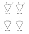
FIG. 5A is a representation of an exemplary turbine engine component composed of a material types I and II; -
FIG. 5B is a representation of another exemplary turbine engine component composed of a material types I and II; -
FIG. 6A is a representation of yet another exemplary turbine engine component composed of material types I and II; and -
FIG. 6B is a representation of still yet another exemplary turbine engine component composed of a baseline material and material type II. - Like reference numbers and designations in the various drawings indicate like elements.
- Referring now to
FIG. 3 , the thermal stresses experienced by a turbine engine component, e.g., aturbine vane 10, may be demonstrated using a thermal stress model represented by a two bar system. The thermal stress in atrailing edge 12 of thevane 10 may be represented by the two bar system by the following equation:
where the subscript LE denotes the leading edge, the subscript TE denotes the trailing edge, T is the temperature, α is the thermal expansion coefficient, A is the cross-sectional area, and E is the Young's modulus. Formula (1) assumes a zero stress state at room temperature. If this is not true and a stress free state exists at another temperature To, then Formula (1) should be modified as follows:
- In accordance with both Formulas (1) and (2), the thermal stress at the
trailing edge 12 may be primarily controlled by the thermal expansion mismatch (TLEαLE-TTEαTE) and the leading edge and trailing edge stiffness and area ratios. First, we turn our attention to the thermal expansion mismatch. Assuming that TLE is greater than TTE as in the case of an engine shutdown state, the thermal expansion coefficient at thetrailing edge 12 should be higher than the thermal expansion coefficient at the leadingedge 14 in order to lower the thermal stress. Further, the temperature difference between the leadingedge 14 and thetrailing edge 12 may be minimized by increasing the heat capacity and by reducing the heat conductivity of thetrailing edge 12. The trailing edge stress may also be lowered by increasing the trailing edge section area and lowering the stiffness of thetrailing edge 12. It is also important to note the difference in thermal physical properties between the leadingedge 14 andtrailing edge 12 may also be realized by changing the material composition or microstructure during processing so that the trailing edge material has a higher thermal expansion coefficient and thermal capacity, but lower heat conductivity compared to the leading edge material. - The impact of key material and geometrical properties on the thermal stress of a turbine vane under shutdown conditions is summarized in the table provided below.
TABLE of Optimal Material/Geometrical Property Changes on Leading and Trailing Edges in order to reduce overall thermal stress. Property Leading Edge Trailing Edge Effect Coefficient of thermal expansion ↑ ↓ Reduce thermal growth mismatch between LE and TE Heat Capacity ↓ ↑ Reduce temperature difference between LE and TE Conductivity ↑ ↓ Reduce temperature difference between LE and TE Modulus E ↓ ↑ Reduce stiffness mismatch between LE and TE Section area ↓ ↑ Reduce stiffness mismatch between LE and TE - Based upon the impact of these key material and geometric properties, an exemplary turbine vane microstructure described herein may be controlled by the proper choice of fabrication and/or manufacturing technique(s), materials and subsequent processing steps. By selectively positioning material(s) within the structure of the exemplary turbine vane described herein, the properties critical for performance may be controlled. Specifically, the aforementioned properties such as the CTE, heat capacity, thermal conductivity and Young's Modulus can be controlled locally within the bulk article of the exemplary turbine vane by the selective placement of various materials. The exemplary process described herein, and resulting exemplary turbine vane, may be applied to a broad range of material such as ceramic, metallic and composites.
- The exemplary turbine vanes described herein are composed of a graded composition designed to at least substantially reduce and/or eliminate the obstacles associated with severe thermal stress(es) experienced by prior art turbine engine components.
- The term "graded composition" means any one of the following: (1) a composition composed of different materials such as metal, ceramic, metal alloy, composite particle, mixed powders, multiple metals or ceramics, and the like; (2) a composition composed of materials having different morphologies, e.g., spherical, blocky, acicular, whiskers, fibrous, and the like; (3) a composition composed of materials having different microstructures, e.g., amorphous, crystalline, crystalline phase, and the like; or (4) a composition composed of materials exhibiting the physical properties of the aforementioned compositions (1), (2) and (3), wherein the composition exhibits a graded structure such as linear, non-linear, step functions, quadratic, polynomial, point defects and other mathematical strategies for generation of grading as known to one of ordinary skill in the art.
- The materials mentioned in describing the aforementioned compositions may be produced using suitable fabrication techniques include solid freeform fabrication technologies (SFF) or rapid manufacturing techniques such as fused deposition modeling (FDM), extrusion freeform fabrication (EFF), laser-enhanced net shaping (LENS), 3-dimensional printing (3DP), ink jet printing, selective laser sintering (SLS) and the like; combinations comprising at least one of the foregoing techniques, and the like. SFF techniques can produce parts from metal, ceramic and polymers, as well as mixed or composite powders and alloys. Certain techniques are more amenable to the use of powder-based materials while other techniques are more suitable for bulk materials in wire or vapor form. For example, FDM is an extrusion-based process for thermoplastics that has been modified to incorporate metal, ceramic and mixed powders suitable for fabricating metal, ceramic and mixed metal/ceramic objects. Also, EFF is used to fabricate functionally graded materials (FGM) by extrusion of two dissimilar materials. Generally, FGMs consist of a synergistic combination of two materials, e.g., a metal and a ceramic. However, it is conceivable that two or more dissimilar metal or ceramic phases having a continuous composition gradient between their respective end members, e.g., ceramic phase 1 and ceramic phase 2. SLS techniques permit sintering polymer coated metal or ceramic powders. Other laser-based techniques such as LENS are used to directly melt a wire or powder feedstock of the target composition. In addition to the fabrication techniques described above, the composite material may form a first phase and a second phase, where the second phase is composed of at least one and/or a plurality of pores, that is, a residual porosity. The residual porosity may be infiltrated with a metal such as copper or bronze, or other aforementioned material, to densify the part and create a "composite" part containing uniformly distributed steel and copper, for example. The residual porosity may also be infiltrated with a polymer, polymer blend or filled polymer system designed to convert to select metal and/or ceramic phase(s). One example of such a method is described in
U.S.P.N. 6,228,437 to Schmidt , assigned to United Technologies Corporation, which is incorporated by reference herein in its entirety. - Referring now to the flowchart of
FIG. 4 , the exemplary turbine engine components described herein may be manufactured atstep 16 using any one of a number of techniques known to one of ordinary skill in the art. For example, suitable techniques may include rapid prototyping processes, rapid manufacturing processes such as 3-D printing methods, laser deposition techniques, fused deposition modeling, thermal spray techniques, investment casting, combinations comprising at least one of the foregoing methods, and the like. In addition to or in the alternative to direct fabrication of solid articles, turbine engine components exhibiting a residual porosity may be infiltrated, or back-filled, atstep 18 with another desirable phase or combination of phases. An example of such fabrication techniques is disclosed inU.S.P.N. 6,228,437 to Schmidt. In addition to or in the alternative to direct fabrication of solid articles, turbine engine components may be subsequently processed (e.g. thermally, chemically, etc.) to convert one or more phases within the structure to another phase, or to completely remove one or more phases (e.g. leaching, melting, etc.). When completed, at least a portion, if not in their entirety, of the exemplary turbine engine components may also be coated. Representative suitable coatings include those inU.S.P.N. 6,924,040 ,6,730,422 ,6,284,323 ,6,902,836 , and7,063,894 assigned to United Technologies Corporation, and incorporated by reference herein in their entirety. Coating architectures and deposition methods will be selected depending on the substrate composition (e.g. metal, ceramic, ceramic matrix composite, alloy, etc.). - Referring now to
FIGS. 5A and 5B , representations of a pair of exemplaryturbine engine components Turbine engine components leading edge edge FIG. 5A . Conversely, it is desirable to increase the CTE of the trailingedge edge FIG. 5B - For exemplary purposes, material type I has a higher CTE value, and likewise a higher heat capacity, than material type II. In
FIG. 5A , exemplaryturbine engine component 20 exhibits a smooth (linear) gradient of the two materials between theleading edge 24 and trailingedge 22. As a result, the leadingedge 24 region has a reduced heat capacity relative to the trailingedge 22 region. - For exemplary purposes, material type II has a relatively low CTE and heat capacity compared to material type I. In the alternative to the exemplary grading strategies shown in
FIG. 5A , a non-linear grading strategy may be utilized. Referring now toFIG. 5B , a discontinuous step function may be employed so that a greater amount of material type II may be applied at the trailingedge 32, with decreasing amounts of material type II positioned nearer the leadingedge 34 of the exemplaryturbine engine component 30. - Referring to
FIGS. 6A and 6B , representations of another pair of exemplary turbine engine components described herein are shown. As also mentioned above, it is desirable to have a higher thermal conductivity and stiffness (as measured by Young's modulus) in the vicinity of the leading edge. For purposes of illustration, material type I exhibits both a higher thermal conductivity and greater stiffness compared to material type II. Referring now toFIG. 5A , an exemplary turbine engine component 40 may be manufactured to possess a continuous grading between the material type II at the trailing edge to the material type I at the leading edge. - In the alternative to the exemplary turbine engine component of
FIG. 6A , an exemplary turbine engine component 50 ofFIG. 6B may be composed of a baseline material being modified in a discontinuous manner by the introduction of greater concentrations of material type II having a relatively higher thermal conductivity and stiffness as compared to the baseline material. - The exemplary turbine engine components described herein possess distinct advantages over turbine engine components of the prior art. First, the functionally graded materials used to manufacture these components may be tailored to exhibit the most advantageous combination of the mechanical and thermal properties disclosed above in Table 1. Prior art turbine engine components composed of only ceramic or metal only possess and exhibit certain mechanical properties under certain operating conditions, e.g., start-up and shut-down. In contrast, the functionally graded materials used herein exhibit an advantageous combination of mechanical and thermal properties across a broad range of operating conditions. Secondly, the development of rapid manufacturing techniques have progressed to the point where the costs involved are comparable and commensurate with certain casting processes typically employed to manufacture turbine engine components. Other advantages and benefits to using functionally graded materials in constructing turbine engine components include the potential for significant weight reduction, tailorable erosion and abrasion resistance, more efficient heat transfer and/or increased fuel efficiency.
- One or more embodiments of the present invention have been described. Nevertheless, it will be understood that various modifications may be made without departing from the scope of the invention. Accordingly, other embodiments are within the scope of the following claims.
Claims (15)
- A process for manufacturing a turbine engine component (20;30) comprising fabricating a turbine engine component (20;30) using a functionally graded composite material having at least two different materials.
- The process of claim 1, wherein fabricating comprises grading said at least two different materials to form said functionally graded material of said turbine engine component (20;30).
- The process of claim 2, wherein grading comprises at least one of the following types of grading: linear, non-linear, step functions, quadratic, polynomial, point defects, and combinations thereof.
- The process of claim 1, wherein said at least two different materials each exhibit different morphologies or different microstructures or both different morphologies and different microstructures.
- The process of claim 1, wherein said turbine engine component (20;30) comprises a functionally graded composite material structure having a first phase and a second phase.
- The process of claim 5, further comprising infiltrating at least a portion of said second phase with at least one material.
- The process of claim 6, wherein said second phase comprises a residual porosity.
- The process of claim 6 or 7, wherein said at least one material comprises at least one of the following materials: metal, metal alloy, ceramic, composite particle, mixed powders and combinations thereof.
- The process of any preceding claim, wherein fabricating comprises at least one of the following processes: solid freeform fabricating, selective laser sintering, fused deposition modeling, extrusion freeform fabricating, laser enhanced net shaping, 3-dimensional printing, ink jet printing and combinations thereof.
- The process of any preceding claim, wherein said at least two different materials comprises at least two of the following materials: metal, ceramic, metal alloy, mixed powders, composite particle, multiple metals or ceramics, and combinations thereof.
- The process of any preceding claim, wherein said at least two different materials are at least two different powdered materials.
- A turbine vane, comprising:a platform; andat least one airfoil (20;30) mounted to said platform and having a trailing edge (22;32) and a leading edge (24;34),wherein the vane is composed of a functionally graded material having a first material and a second material,
wherein said trailing edge (22;32) includes a greater amount of said first material than said second material, and said leading edge (24;34) includes a greater amount of said second material than said first material. - The turbine vane of claim 12, wherein said first material possesses a greater coefficient of thermal expansion and lower heat capacity than a coefficient of thermal expansion and heat capacity of said second material.
- The turbine vane of claim 12 or 13, wherein said second material possesses a greater thermal conductivity value and greater stiffness than a thermal conductivity value and stiffness of said first material.
- The turbine vane of any of claims 12 to 14, wherein said functionally graded composite material comprises at least two of the following materials: metal, metal alloy, ceramic, mixed powders, composite particle, multiple metals or ceramics, and combinations thereof.
Applications Claiming Priority (1)
| Application Number | Priority Date | Filing Date | Title |
|---|---|---|---|
| US11/829,391 US7967570B2 (en) | 2007-07-27 | 2007-07-27 | Low transient thermal stress turbine engine components |
Publications (3)
| Publication Number | Publication Date |
|---|---|
| EP2025777A2 true EP2025777A2 (en) | 2009-02-18 |
| EP2025777A3 EP2025777A3 (en) | 2011-04-06 |
| EP2025777B1 EP2025777B1 (en) | 2018-11-21 |
Family
ID=39878497
Family Applications (1)
| Application Number | Title | Priority Date | Filing Date |
|---|---|---|---|
| EP08251824.2A Ceased EP2025777B1 (en) | 2007-07-27 | 2008-05-27 | Low transient thermal stress turbine vane |
Country Status (2)
| Country | Link |
|---|---|
| US (1) | US7967570B2 (en) |
| EP (1) | EP2025777B1 (en) |
Cited By (7)
| Publication number | Priority date | Publication date | Assignee | Title |
|---|---|---|---|---|
| FR2971178A1 (en) * | 2011-02-09 | 2012-08-10 | Snecma | PROCESS FOR THE PRODUCTION OF GUIDE VANE |
| EP2559787A1 (en) | 2011-08-17 | 2013-02-20 | Rolls-Royce Deutschland Ltd & Co KG | Method for producing a component for high thermal loads, a component that can be created using the method and an aircraft engine with the component |
| DE102013214908A1 (en) * | 2013-07-30 | 2015-02-05 | Siemens Aktiengesellschaft | A graded metal layer device, method for making the graded metal layer device, and use of the graded metal layer device |
| EP3095551A1 (en) * | 2015-05-21 | 2016-11-23 | Rolls-Royce plc | Additive layer repair of a metallic component |
| FR3055352A1 (en) * | 2016-08-29 | 2018-03-02 | Safran Aircraft Engines | DUST FOR TURBOMACHINE WITH A STRUCTURE REDUCING THE RISK OF CREAM APPEARANCE |
| EP4497569A1 (en) * | 2023-07-24 | 2025-01-29 | Hamilton Sundstrand Corporation | Metal plated additively manufactured plastic acm housings with internal thermally adaptive structure |
| US12384515B2 (en) | 2023-09-08 | 2025-08-12 | Hamilton Sundstrand Corporation | Airfoil formed of thermally adaptive materials and a thermoelectric junction |
Families Citing this family (32)
| Publication number | Priority date | Publication date | Assignee | Title |
|---|---|---|---|---|
| US8206098B2 (en) * | 2007-06-28 | 2012-06-26 | United Technologies Corporation | Ceramic matrix composite turbine engine vane |
| US8210803B2 (en) * | 2007-06-28 | 2012-07-03 | United Technologies Corporation | Ceramic matrix composite turbine engine vane |
| US8224617B2 (en) * | 2009-07-22 | 2012-07-17 | Korea Hydro & Nuclear Power Co., Ltd. | Apparatus and method for calculating temperature dependent green's function using weight function |
| US20110116912A1 (en) * | 2009-11-13 | 2011-05-19 | Mccall Thomas | Zoned discontinuous coating for high pressure turbine component |
| US9429029B2 (en) | 2010-09-30 | 2016-08-30 | Pratt & Whitney Canada Corp. | Gas turbine blade and method of protecting same |
| US9587645B2 (en) | 2010-09-30 | 2017-03-07 | Pratt & Whitney Canada Corp. | Airfoil blade |
| GB2490087B (en) | 2010-11-29 | 2016-04-27 | Halliburton Energy Services Inc | Forming objects by infiltrating a printed matrix |
| GB2485848B (en) | 2010-11-29 | 2018-07-11 | Halliburton Energy Services Inc | Improvements in heat flow control for molding downhole equipment |
| US10059431B2 (en) | 2011-06-09 | 2018-08-28 | United Technologies Corporation | Method and apparatus for attaching components having dissimilar rates of thermal expansion |
| US9290261B2 (en) | 2011-06-09 | 2016-03-22 | United Technologies Corporation | Method and assembly for attaching components |
| US9169739B2 (en) * | 2012-01-04 | 2015-10-27 | United Technologies Corporation | Hybrid blade outer air seal for gas turbine engine |
| US11000899B2 (en) | 2012-01-29 | 2021-05-11 | Raytheon Technologies Corporation | Hollow airfoil construction utilizing functionally graded materials |
| US9427835B2 (en) * | 2012-02-29 | 2016-08-30 | Pratt & Whitney Canada Corp. | Nano-metal coated vane component for gas turbine engines and method of manufacturing same |
| US8733422B2 (en) | 2012-03-26 | 2014-05-27 | Apple Inc. | Laser cladding surface treatments |
| US20140003923A1 (en) | 2012-07-02 | 2014-01-02 | Peter Finnigan | Functionally graded composite fan containment case |
| US20140126995A1 (en) | 2012-11-06 | 2014-05-08 | General Electric Company | Microchannel cooled turbine component and method of forming a microchannel cooled turbine component |
| US20150003995A1 (en) * | 2012-11-14 | 2015-01-01 | United Technologies Corporation | Aircraft engine component with locally tailored materials |
| WO2014093826A2 (en) | 2012-12-14 | 2014-06-19 | United Technologies Corporation | Multi-shot casting |
| EP3513889B1 (en) | 2012-12-14 | 2021-04-14 | Raytheon Technologies Corporation | Alloy and hybrid turbine blade for improved engine performance or architecture |
| US9650898B2 (en) * | 2012-12-27 | 2017-05-16 | United Technologies Corporation | Airfoil with variable profile responsive to thermal conditions |
| US20140216043A1 (en) * | 2013-02-06 | 2014-08-07 | Weidong Cai | Combustor liner for a can-annular gas turbine engine and a method for constructing such a liner |
| US10487667B2 (en) | 2013-07-01 | 2019-11-26 | United Technologies Corporation | Airfoil, and method for manufacturing the same |
| US20160202101A1 (en) * | 2015-01-12 | 2016-07-14 | Douglas Ray Sparks | Sensor structures and methods of forming using three-dimensional printing techniques |
| US9982684B2 (en) * | 2015-08-07 | 2018-05-29 | General Electric Company | Hybrid metal compressor blades |
| US10196898B2 (en) | 2015-11-24 | 2019-02-05 | General Electric Company | Turbine airfoil with passive morphing structure |
| US10856443B2 (en) | 2018-06-06 | 2020-12-01 | Apple Inc. | Cladded metal structures for dissipation of heat in a portable electronic device |
| US11286782B2 (en) | 2018-12-07 | 2022-03-29 | General Electric Company | Multi-material leading edge protector |
| US11318553B2 (en) | 2019-01-04 | 2022-05-03 | Raytheon Technologies Corporation | Additive manufacturing of laminated superalloys |
| CN110008530B (en) * | 2019-03-15 | 2020-04-24 | 东南大学 | Distributed probability modeling method for space flexible composite material |
| JP7144374B2 (en) * | 2019-07-29 | 2022-09-29 | 日立Geニュークリア・エナジー株式会社 | TRANSITION PIECE MANUFACTURING METHOD AND TRANSITION PIECE |
| US11753942B1 (en) * | 2022-04-11 | 2023-09-12 | General Electric Company | Frangible airfoils |
| CN119844167A (en) * | 2023-10-18 | 2025-04-18 | 中国航发商用航空发动机有限责任公司 | Turbine blade |
Citations (9)
| Publication number | Priority date | Publication date | Assignee | Title |
|---|---|---|---|---|
| WO1992000182A1 (en) | 1990-06-29 | 1992-01-09 | Flexline Services Ltd. | A process for manufacturing reinforced composites and filament material for use in said process |
| US5837960A (en) | 1995-08-14 | 1998-11-17 | The Regents Of The University Of California | Laser production of articles from powders |
| US6228437B1 (en) | 1998-12-24 | 2001-05-08 | United Technologies Corporation | Method for modifying the properties of a freeform fabricated part |
| US6284323B1 (en) | 1996-12-12 | 2001-09-04 | United Technologies Corporation | Thermal barrier coating systems and materials |
| US6730422B2 (en) | 2002-08-21 | 2004-05-04 | United Technologies Corporation | Thermal barrier coatings with low thermal conductivity |
| US6902836B2 (en) | 2003-05-22 | 2005-06-07 | United Technologies Corporation | Environmental barrier coating for silicon based substrates such as silicon nitride |
| US6924040B2 (en) | 1996-12-12 | 2005-08-02 | United Technologies Corporation | Thermal barrier coating systems and materials |
| US7063894B2 (en) | 2003-05-22 | 2006-06-20 | United Technologies Corporation | Environmental barrier coating for silicon based substrates |
| EP1743729A2 (en) | 2005-06-30 | 2007-01-17 | General Electric Company | Niobium silicide-based turbine components with composition graded portion; methods of laser cladding of niobium silicide on a turbin component, also used for repairing |
Family Cites Families (13)
| Publication number | Priority date | Publication date | Assignee | Title |
|---|---|---|---|---|
| US4820358A (en) * | 1987-04-01 | 1989-04-11 | General Electric Company | Method of making high strength superalloy components with graded properties |
| US4900635A (en) * | 1987-07-27 | 1990-02-13 | Williams International Corporation | Multi-alloy turbine rotor disk |
| DE3821005A1 (en) | 1988-06-22 | 1989-12-28 | Mtu Muenchen Gmbh | Metal/ceramic composite blade |
| JPH09195067A (en) * | 1996-01-12 | 1997-07-29 | Toshiba Corp | Heat resistant parts |
| US6641893B1 (en) * | 1997-03-14 | 2003-11-04 | Massachusetts Institute Of Technology | Functionally-graded materials and the engineering of tribological resistance at surfaces |
| US6391251B1 (en) * | 1999-07-07 | 2002-05-21 | Optomec Design Company | Forming structures from CAD solid models |
| US6325593B1 (en) * | 2000-02-18 | 2001-12-04 | General Electric Company | Ceramic turbine airfoils with cooled trailing edge blocks |
| US6709230B2 (en) * | 2002-05-31 | 2004-03-23 | Siemens Westinghouse Power Corporation | Ceramic matrix composite gas turbine vane |
| US7316057B2 (en) * | 2004-10-08 | 2008-01-08 | Siemens Power Generation, Inc. | Method of manufacturing a rotating apparatus disk |
| US7247002B2 (en) * | 2004-12-02 | 2007-07-24 | Siemens Power Generation, Inc. | Lamellate CMC structure with interlock to metallic support structure |
| US7217088B2 (en) * | 2005-02-02 | 2007-05-15 | Siemens Power Generation, Inc. | Cooling fluid preheating system for an airfoil in a turbine engine |
| US7422771B2 (en) * | 2005-09-01 | 2008-09-09 | United Technologies Corporation | Methods for applying a hybrid thermal barrier coating |
| WO2007092363A2 (en) * | 2006-02-03 | 2007-08-16 | San Diego State University | Hybrid slip casting-electrophoretic deposition (epd) process |
-
2007
- 2007-07-27 US US11/829,391 patent/US7967570B2/en active Active
-
2008
- 2008-05-27 EP EP08251824.2A patent/EP2025777B1/en not_active Ceased
Patent Citations (9)
| Publication number | Priority date | Publication date | Assignee | Title |
|---|---|---|---|---|
| WO1992000182A1 (en) | 1990-06-29 | 1992-01-09 | Flexline Services Ltd. | A process for manufacturing reinforced composites and filament material for use in said process |
| US5837960A (en) | 1995-08-14 | 1998-11-17 | The Regents Of The University Of California | Laser production of articles from powders |
| US6284323B1 (en) | 1996-12-12 | 2001-09-04 | United Technologies Corporation | Thermal barrier coating systems and materials |
| US6924040B2 (en) | 1996-12-12 | 2005-08-02 | United Technologies Corporation | Thermal barrier coating systems and materials |
| US6228437B1 (en) | 1998-12-24 | 2001-05-08 | United Technologies Corporation | Method for modifying the properties of a freeform fabricated part |
| US6730422B2 (en) | 2002-08-21 | 2004-05-04 | United Technologies Corporation | Thermal barrier coatings with low thermal conductivity |
| US6902836B2 (en) | 2003-05-22 | 2005-06-07 | United Technologies Corporation | Environmental barrier coating for silicon based substrates such as silicon nitride |
| US7063894B2 (en) | 2003-05-22 | 2006-06-20 | United Technologies Corporation | Environmental barrier coating for silicon based substrates |
| EP1743729A2 (en) | 2005-06-30 | 2007-01-17 | General Electric Company | Niobium silicide-based turbine components with composition graded portion; methods of laser cladding of niobium silicide on a turbin component, also used for repairing |
Cited By (11)
| Publication number | Priority date | Publication date | Assignee | Title |
|---|---|---|---|---|
| FR2971178A1 (en) * | 2011-02-09 | 2012-08-10 | Snecma | PROCESS FOR THE PRODUCTION OF GUIDE VANE |
| US9103215B2 (en) | 2011-02-09 | 2015-08-11 | Snecma | Method of producing a guide vane |
| EP2559787A1 (en) | 2011-08-17 | 2013-02-20 | Rolls-Royce Deutschland Ltd & Co KG | Method for producing a component for high thermal loads, a component that can be created using the method and an aircraft engine with the component |
| DE102011081112A1 (en) | 2011-08-17 | 2013-02-21 | Rolls-Royce Deutschland Ltd & Co Kg | Method for producing a component for high thermal loads, a component produced by the method and an aircraft engine with the component |
| US9587317B2 (en) | 2011-08-17 | 2017-03-07 | Rolls-Royce Deutschland Ltd & Co Kg | Method for the manufacture of a component for high thermal loads, a component producible by this method and an aircraft engine provided with the component |
| DE102013214908A1 (en) * | 2013-07-30 | 2015-02-05 | Siemens Aktiengesellschaft | A graded metal layer device, method for making the graded metal layer device, and use of the graded metal layer device |
| EP3095551A1 (en) * | 2015-05-21 | 2016-11-23 | Rolls-Royce plc | Additive layer repair of a metallic component |
| US10487659B2 (en) | 2015-05-21 | 2019-11-26 | Rolls-Royce Plc | Additive layer repair of a metallic component |
| FR3055352A1 (en) * | 2016-08-29 | 2018-03-02 | Safran Aircraft Engines | DUST FOR TURBOMACHINE WITH A STRUCTURE REDUCING THE RISK OF CREAM APPEARANCE |
| EP4497569A1 (en) * | 2023-07-24 | 2025-01-29 | Hamilton Sundstrand Corporation | Metal plated additively manufactured plastic acm housings with internal thermally adaptive structure |
| US12384515B2 (en) | 2023-09-08 | 2025-08-12 | Hamilton Sundstrand Corporation | Airfoil formed of thermally adaptive materials and a thermoelectric junction |
Also Published As
| Publication number | Publication date |
|---|---|
| US7967570B2 (en) | 2011-06-28 |
| EP2025777A3 (en) | 2011-04-06 |
| US20090028697A1 (en) | 2009-01-29 |
| EP2025777B1 (en) | 2018-11-21 |
Similar Documents
| Publication | Publication Date | Title |
|---|---|---|
| EP2025777B1 (en) | Low transient thermal stress turbine vane | |
| US8043684B2 (en) | Low transient and steady state thermal stress disk shaped components | |
| KR102168845B1 (en) | Manufacturing method of cobalt base alloy laminate molding body | |
| EP3702069B1 (en) | Titanium aluminide components from articles formed by consolidation processes | |
| US10801088B2 (en) | Nickel base super alloys and methods of making the same | |
| EP3010671B1 (en) | Method for producing a three-dimensional article | |
| JP6713071B2 (en) | Method for manufacturing cobalt-based alloy laminated body | |
| EP2700459B1 (en) | Method for manufacturing a three-dimensional article | |
| JP7358034B2 (en) | How to make pre-sintered preforms | |
| US5960249A (en) | Method of forming high-temperature components and components formed thereby | |
| US20150003997A1 (en) | Method of forming hybrid metal ceramic components | |
| US20160273368A1 (en) | Blade of a turbomachine made of different materials and method for the production thereof | |
| US20080237403A1 (en) | Metal injection molding process for bimetallic applications and airfoil | |
| WO2020121367A1 (en) | Cobalt-based alloy laminate molded body, cobalt-based alloy product, and manufacturing method of these | |
| KR20210027391A (en) | Cobalt-based alloy products and cobalt-based alloy articles | |
| US12385405B2 (en) | Wear resistant article and method of making | |
| JP2018150223A (en) | Method of forming preform ceramic matrix composite mold and method of forming ceramic matrix composite component | |
| CN112969545B (en) | Methods for additively produced articles | |
| US20230211418A1 (en) | Method for producing an impact-resistant component, and corresponding impact-resistant component | |
| EP4397788A1 (en) | Wear resistant article and method of making | |
| Gejendhiran et al. | Advancements in functionally graded materials for additive manufacturing | |
| Roccetti Campagnoli | Optimisation of Copper production by laser powder bed fusion (L-PBF) | |
| Ghanavati et al. | Multi-material processing of metallic components by direct additive manufacturing methods: technologies, scientific insights, and industrial applications | |
| CN118291974A (en) | Wear-resistant product and manufacturing method | |
| US20100263821A1 (en) | Super-alloy and stainless steel casting method |
Legal Events
| Date | Code | Title | Description |
|---|---|---|---|
| PUAI | Public reference made under article 153(3) epc to a published international application that has entered the european phase |
Free format text: ORIGINAL CODE: 0009012 |
|
| AK | Designated contracting states |
Kind code of ref document: A2 Designated state(s): AT BE BG CH CY CZ DE DK EE ES FI FR GB GR HR HU IE IS IT LI LT LU LV MC MT NL NO PL PT RO SE SI SK TR |
|
| AX | Request for extension of the european patent |
Extension state: AL BA MK RS |
|
| PUAL | Search report despatched |
Free format text: ORIGINAL CODE: 0009013 |
|
| AK | Designated contracting states |
Kind code of ref document: A3 Designated state(s): AT BE BG CH CY CZ DE DK EE ES FI FR GB GR HR HU IE IS IT LI LT LU LV MC MT NL NO PL PT RO SE SI SK TR |
|
| AX | Request for extension of the european patent |
Extension state: AL BA MK RS |
|
| 17P | Request for examination filed |
Effective date: 20111005 |
|
| AKX | Designation fees paid |
Designated state(s): DE GB |
|
| 17Q | First examination report despatched |
Effective date: 20141203 |
|
| RAP1 | Party data changed (applicant data changed or rights of an application transferred) |
Owner name: UNITED TECHNOLOGIES CORPORATION |
|
| STAA | Information on the status of an ep patent application or granted ep patent |
Free format text: STATUS: EXAMINATION IS IN PROGRESS |
|
| REG | Reference to a national code |
Ref country code: DE Ref legal event code: R079 Ref document number: 602008057992 Country of ref document: DE Free format text: PREVIOUS MAIN CLASS: C23C0028000000 Ipc: F01D0005140000 |
|
| GRAP | Despatch of communication of intention to grant a patent |
Free format text: ORIGINAL CODE: EPIDOSNIGR1 |
|
| STAA | Information on the status of an ep patent application or granted ep patent |
Free format text: STATUS: GRANT OF PATENT IS INTENDED |
|
| RIC1 | Information provided on ipc code assigned before grant |
Ipc: F01D 5/14 20060101AFI20180508BHEP Ipc: F01D 5/28 20060101ALI20180508BHEP |
|
| INTG | Intention to grant announced |
Effective date: 20180530 |
|
| GRAS | Grant fee paid |
Free format text: ORIGINAL CODE: EPIDOSNIGR3 |
|
| GRAA | (expected) grant |
Free format text: ORIGINAL CODE: 0009210 |
|
| STAA | Information on the status of an ep patent application or granted ep patent |
Free format text: STATUS: THE PATENT HAS BEEN GRANTED |
|
| AK | Designated contracting states |
Kind code of ref document: B1 Designated state(s): DE GB |
|
| REG | Reference to a national code |
Ref country code: DE Ref legal event code: R096 Ref document number: 602008057992 Country of ref document: DE |
|
| REG | Reference to a national code |
Ref country code: DE Ref legal event code: R097 Ref document number: 602008057992 Country of ref document: DE |
|
| PLBE | No opposition filed within time limit |
Free format text: ORIGINAL CODE: 0009261 |
|
| STAA | Information on the status of an ep patent application or granted ep patent |
Free format text: STATUS: NO OPPOSITION FILED WITHIN TIME LIMIT |
|
| 26N | No opposition filed |
Effective date: 20190822 |
|
| PGFP | Annual fee paid to national office [announced via postgrant information from national office to epo] |
Ref country code: DE Payment date: 20220420 Year of fee payment: 15 |
|
| REG | Reference to a national code |
Ref country code: DE Ref legal event code: R081 Ref document number: 602008057992 Country of ref document: DE Owner name: RAYTHEON TECHNOLOGIES CORPORATION (N.D.GES.D.S, US Free format text: FORMER OWNER: UNITED TECHNOLOGIES CORPORATION, FARMINGTON, CONN., US |
|
| PGFP | Annual fee paid to national office [announced via postgrant information from national office to epo] |
Ref country code: GB Payment date: 20230420 Year of fee payment: 16 |
|
| REG | Reference to a national code |
Ref country code: DE Ref legal event code: R119 Ref document number: 602008057992 Country of ref document: DE |
|
| PG25 | Lapsed in a contracting state [announced via postgrant information from national office to epo] |
Ref country code: DE Free format text: LAPSE BECAUSE OF NON-PAYMENT OF DUE FEES Effective date: 20231201 |
|
| GBPC | Gb: european patent ceased through non-payment of renewal fee |
Effective date: 20240527 |
|
| PG25 | Lapsed in a contracting state [announced via postgrant information from national office to epo] |
Ref country code: GB Free format text: LAPSE BECAUSE OF NON-PAYMENT OF DUE FEES Effective date: 20240527 |